Testing and loss measurement of HV shell-type shunt-reactors at ...
Testing and loss measurement of HV shell-type shunt-reactors at ...
Testing and loss measurement of HV shell-type shunt-reactors at ...
- No tags were found...

Create successful ePaper yourself
Turn your PDF publications into a flip-book with our unique Google optimized e-Paper software.
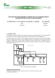
this test voltage without s<strong>at</strong>ur<strong>at</strong>ion <strong>of</strong> the magnetic shield. At <strong>HV</strong> labor<strong>at</strong>ory 180 Hz test voltage isprovided by a gener<strong>at</strong>or th<strong>at</strong> has a low-capacity <strong>of</strong> approxim<strong>at</strong>ely 1.1 MVA, <strong>and</strong> the <strong>shunt</strong>-reactorreactive power <strong>of</strong> 41.1 MVAr was compens<strong>at</strong>ed by a large capacitor bank. Tuning <strong>of</strong> the capacitorbank to resonance with the <strong>shunt</strong>-reactor was difficult <strong>and</strong> to some extent dangerous, as the gener<strong>at</strong>ormay be damaged when loaded with a capacitive impedance. Fluctu<strong>at</strong>ions <strong>of</strong> power frequency madethis tuning difficult since the resonance curve has a steep slope th<strong>at</strong> transl<strong>at</strong>es to a narrow range <strong>of</strong> theoper<strong>at</strong>ional frequency. Besides, the capacitor bank was protected against a faulty capacitor explosionth<strong>at</strong> may initi<strong>at</strong>e fire <strong>of</strong> the whole bank.The winding size is largely determined by the impulse voltage distribution <strong>and</strong> this was optimized by adetailed analysis <strong>of</strong> the electric field distribution in the critically stressed parts <strong>of</strong> the insul<strong>at</strong>ionsystem. Shell-<strong>type</strong> reactor magnetic circuit is more compact <strong>and</strong> less complex to manufacture, sincethere is no need to install magnetic inserts th<strong>at</strong> restrain magnetic flux inside the winding. In the <strong>shell</strong><strong>type</strong> <strong>shunt</strong>-reactor the magnetic shields are <strong>at</strong>tached to the tank inner side to prevent the stray fluxfrom penetr<strong>at</strong>ing the tank wall, <strong>and</strong> to reduce the stray <strong>loss</strong> (figure 1).An important reduction <strong>of</strong> the copper-<strong>loss</strong> was achieved by using the continuously transposed wire,r<strong>at</strong>her than the conventional solid-copper conductor. The winding wound with the transposed wireensures a sufficient mechanical rigidity owing to the <strong>shell</strong>-<strong>type</strong> geometry. As compared to powertransformers, the <strong>shunt</strong> reactor is not prone to short-circuit currents, <strong>and</strong> no special requirements areimposed on the mechanical strength <strong>of</strong> the winding.An optimum solution <strong>of</strong> design problems <strong>and</strong> development <strong>of</strong> the resonant test-circuits, as well as thecomplex process <strong>of</strong> <strong>loss</strong> <strong>measurement</strong>s are addressed in this paper.Figure. 1. Shell Type Shunt-Reactor showing magnetic flux lines <strong>and</strong> magnetic shields.2. <strong>HV</strong> insul<strong>at</strong>ion designThe stress distribution within the selected parts <strong>of</strong> the windings has been calcul<strong>at</strong>ed, <strong>and</strong> the dielectricstrength <strong>of</strong> oil- gaps was checked against “Weidmann Reference Curve - WRC”. This consisted inplotting the electric field along a chosen filed line in the critically stressed area, calcul<strong>at</strong>ion <strong>of</strong> thecumul<strong>at</strong>ive field E cum (x) distribution, <strong>and</strong> comparison to the WRC th<strong>at</strong> is expressed by the formula:E cum (x) = 2.3·E o /x 0.37 [kV/mm] ------ ( 1 )A factor 2.3 is introduced to account for the impulse test conditions, <strong>and</strong> E o =18 kV/mm corresponds tothe paper-co<strong>at</strong>ed electrodes. A safety margin <strong>of</strong> <strong>at</strong> least 30% was <strong>at</strong>tained in all oil-gaps. The <strong>shell</strong><strong>type</strong>reactor winding is shown schem<strong>at</strong>ically in Figure 2.2
Figure. 2. The electric-field distribution within the <strong>shunt</strong>-reactor insul<strong>at</strong>ion in vicinity <strong>of</strong> <strong>HV</strong>terminal.The higher electric field is indic<strong>at</strong>ed by a lighter tint <strong>of</strong> gray color, <strong>and</strong> contours <strong>of</strong>individual turns, barriers <strong>and</strong> coils are traced with black line.Figure 3. Equipotential lines plotted every 10 kV in the critically stressed area <strong>and</strong> the electric fieldE(x), as well as the cumul<strong>at</strong>ive field E cum (x) distribution in the examined oil-gap #1 under impulse test.An example <strong>of</strong> the Safety Margin (SM) calcul<strong>at</strong>ion <strong>of</strong> the oil-gap #1: the cumul<strong>at</strong>ive field <strong>at</strong> the-oilgap end E cum (5.74)≈13.0 kV/mm, <strong>and</strong> the withst<strong>and</strong> field calcul<strong>at</strong>ed according to Weidmann ReferenceCurve (WRC) E WRC = 2.3 * 18/5.47 0.37 = 2.3 * 9.42 = 21.7 kV/mm. The SM <strong>of</strong> the oil-gap #1 is givenby:SM = 2 * [E WRC (5.74)-E cum (5.74)]/[E WRC (5.74) + E cum (5.74)]=2 * (21.7-13.0)/(21.7+13.0) ≈ 50%3. Dielectric tests <strong>of</strong> the Shunt-ReactorThe <strong>shunt</strong>-reactor has passed all dielectric tests specified by the st<strong>and</strong>ards, but the moststringent insul<strong>at</strong>ion test consists in an applic<strong>at</strong>ion <strong>of</strong> the low-frequency test-voltage th<strong>at</strong>amounts to U t =150% <strong>of</strong> 400 /√3 kV = 346 kV for one hour, <strong>and</strong> <strong>measurement</strong> <strong>of</strong> partialdischarges th<strong>at</strong> should not exceed 300 pC. The test voltage <strong>of</strong> ~180 Hz is gener<strong>at</strong>ed by 1.1MVA rot<strong>at</strong>ing machine driven by an asynchronous motor.However the reactive power <strong>of</strong> the Shunt-Reactor <strong>at</strong>tains S = U t 2 /X L = 37.5 MVAr, whereX L =2π·180·2.83=3.2 kΩ <strong>and</strong> L=2.83 H. To compens<strong>at</strong>e the reactive power, a large capacitor bank isneeded with the capacitance tuned to resonance with the <strong>shunt</strong> reactor a little above the test voltagefrequency. The capacitor bank has to be oper<strong>at</strong>ed <strong>at</strong> a lower voltage to avoid partial discharges fromthe six-level supporting structure <strong>and</strong> connections between the capacitors. Therefore a step-uptransformer has to be introduced between the capacitor bank <strong>and</strong> the <strong>shunt</strong> reactor. The short-circuitreactance <strong>of</strong> this transformer has to be accounted for in calcul<strong>at</strong>ion <strong>of</strong> the compens<strong>at</strong>ing bankcapacitance.3
The resonance curve has a very high Q-factor determined mainly by the reactor <strong>and</strong> step-uptransformer <strong>loss</strong>. A r<strong>at</strong>io <strong>of</strong> the reactive <strong>and</strong> <strong>loss</strong> power is approxim<strong>at</strong>ely 500:1, <strong>and</strong> the resonancecharacteristic has a very steep slope in the oper<strong>at</strong>ing range. This results in a vari<strong>at</strong>ion <strong>of</strong> the testvoltage caused by power frequency fluctu<strong>at</strong>ion <strong>of</strong> approxim<strong>at</strong>ely ±0.3Hz in the supply <strong>of</strong> the gener<strong>at</strong>ordriving motor. The test frequency vari<strong>at</strong>ion is nearly three times higher, <strong>and</strong> the working point <strong>of</strong> theresonant test circuit moves by ±1Hz during one-hour test.To <strong>at</strong>tain the test voltage on the examined <strong>shunt</strong> reactor the resonant test-circuit power must be ~ 40times higher than the power available from the gener<strong>at</strong>or. On another h<strong>and</strong>, loading the gener<strong>at</strong>or withthe capacitive load may result in an uncontrolled spinning <strong>and</strong> destruction <strong>of</strong> the rot<strong>at</strong>ing machine. Forthis reason, an utmost care shall be taken to oper<strong>at</strong>e the test circuit on the inductive load side <strong>of</strong> theresonance curve. In consequence, the test frequency has to be confined in a narrow oper<strong>at</strong>ing-rangeth<strong>at</strong> is limited by the test-circuit resonant frequency <strong>and</strong> by the lowest frequency <strong>at</strong> which the testvoltage is <strong>at</strong>tained. A final tuning <strong>of</strong> the resonant test-circuit was performed by changing regul<strong>at</strong>iontaps <strong>of</strong> the step-up transformer, <strong>and</strong> by connecting or disconnecting capacitors from each level <strong>of</strong> thecompens<strong>at</strong>ion bank. This was somewh<strong>at</strong> tedious procedure, but unavoidable since no regul<strong>at</strong>edfrequencygener<strong>at</strong>or is available in the <strong>HV</strong> labor<strong>at</strong>ory.The actual test voltage vari<strong>at</strong>ions during most time the test time have stayed within ±3 kV as measuredon the examined <strong>shunt</strong> reactor. Occasionally ±9 kV short-time fluctu<strong>at</strong>ions were recorded.The test-circuit was simul<strong>at</strong>ed using Micro-Cap program. A computer model <strong>of</strong> the test-circuit isshown in Figure. 4, <strong>and</strong> the frequency characteristic <strong>of</strong> the resonant test set-up parameters is plotted inFigure. 5.Figure. 4. The computer model composed <strong>of</strong> the test-voltage source V1, the gener<strong>at</strong>or <strong>and</strong> itstransformer inductance L gen <strong>and</strong> resistance R gen , the compens<strong>at</strong>ion bank capacitance C comp<strong>and</strong> resistance R capacit , the step-up transformer inductance L trafo <strong>and</strong> resistance R trafo , <strong>and</strong> theexamined <strong>shunt</strong>-reactor inductance L react <strong>and</strong> resistance R react .The resonant-circuit tuning involves such choice <strong>of</strong> the compens<strong>at</strong>ion bank capacitance, regul<strong>at</strong>ion tap<strong>of</strong> the step-up transformer <strong>and</strong> the reactance <strong>of</strong> the test voltage source to keep the frequencyfluctu<strong>at</strong>ions around the central frequency <strong>at</strong> which the required test voltage is <strong>at</strong>tained. A vari<strong>at</strong>ion <strong>of</strong>the <strong>shunt</strong>-reactor current <strong>and</strong> the gener<strong>at</strong>or current r<strong>at</strong>io, as well as the r<strong>at</strong>io <strong>of</strong> the <strong>shunt</strong>-reactor powerto the gener<strong>at</strong>or power is shown in Figure 6 within the frequency fluctu<strong>at</strong>ion range.The measured parameters <strong>of</strong> the resonant test-circuit followed in general the calcul<strong>at</strong>ed values, but theeffective damping <strong>of</strong> the resonance was different than the assumed value, <strong>and</strong> capacitance <strong>of</strong> thecompens<strong>at</strong>ion bank has slightly changed with respect to th<strong>at</strong> calcul<strong>at</strong>ed from capacitor name-pl<strong>at</strong>e.4. Shunt-Reactor <strong>loss</strong> <strong>measurement</strong>The <strong>shunt</strong>-reactor designer is striving to reduce the <strong>loss</strong> to as small value as possible. On another h<strong>and</strong>,<strong>measurement</strong> <strong>of</strong> such low <strong>loss</strong> represents a major challenge to the test labor<strong>at</strong>ory. The measuringsystem used by all transformer manufacturers for the load-<strong>loss</strong> <strong>measurement</strong> <strong>of</strong> <strong>HV</strong> powertransformers cannot be used for <strong>shunt</strong>-<strong>reactors</strong> [3]. A typical power factor (cosφ) <strong>of</strong> the <strong>shunt</strong>-<strong>reactors</strong>is an order <strong>of</strong> magnitude lower than th<strong>at</strong> <strong>of</strong> large power transformers short-circuited for the load-<strong>loss</strong><strong>measurement</strong>, <strong>and</strong> the <strong>loss</strong>-measuring system uncertainty has to be reduced accordingly. Typical cosφvalue <strong>of</strong> <strong>HV</strong> <strong>shunt</strong>-<strong>reactors</strong> <strong>and</strong> <strong>of</strong> short-circuited large power transformers is shown in Fig. 7.4
∆P14[%] 12 300∆φ [µRad]10815064 1005022000.1 0.3 0.5 0.7 0.9 1.1cos φ [%]Figure 7. Record <strong>of</strong> cosφ <strong>of</strong> <strong>HV</strong> <strong>shunt</strong><strong>reactors</strong>,<strong>and</strong> <strong>of</strong> short-circuited largepower transformers collected by <strong>HV</strong> testlabor<strong>at</strong>oryFigure 8. An uncertainty <strong>of</strong> the measured <strong>loss</strong> ∆Pdepends on the angular uncertainty <strong>of</strong> themeasuring system ∆φ, <strong>and</strong> on the <strong>shunt</strong>-reactorpower factor cosφ, where ∆φ is expressed in microradians(µRad).This is one <strong>of</strong> the most difficult <strong>measurement</strong>s in an industrial <strong>HV</strong> labor<strong>at</strong>ory, where fluctu<strong>at</strong>ions <strong>of</strong>power frequency result in an imbalance <strong>of</strong> the <strong>loss</strong> measuring bridge. To compens<strong>at</strong>e for the frequencyfluctu<strong>at</strong>ions a special double-integr<strong>at</strong>or was installed in the measuring system [7-8]. A conceptualschem<strong>at</strong>ic <strong>of</strong> the Schering bridge is shown in Figure 9 to explain the double integr<strong>at</strong>or function.However the actual bridge used for these <strong>measurement</strong>s is equipped with an autom<strong>at</strong>ic balancingsystem <strong>and</strong> a modern digital display.There is no simple way to calibr<strong>at</strong>e the <strong>shunt</strong>-reactor <strong>loss</strong> measuring circuit, <strong>and</strong> essentially twocalibr<strong>at</strong>ion techniques are used. The first one consists in measuring an uncertainty <strong>of</strong> the <strong>HV</strong> st<strong>and</strong>ardcapacitor, the precision current-transformer <strong>and</strong> the bridge <strong>at</strong> a n<strong>at</strong>ional st<strong>and</strong>ard reference institution,<strong>and</strong> calcul<strong>at</strong>ing the total <strong>loss</strong> measuring uncertainty. This procedure is popular <strong>at</strong> the European testlabor<strong>at</strong>ories <strong>and</strong> accepted by inspectors <strong>of</strong> utilities th<strong>at</strong> buy the <strong>shunt</strong>-<strong>reactors</strong>. An American practicerequires an on-site calibr<strong>at</strong>ion <strong>of</strong> the whole <strong>loss</strong>-measuring system, preferably with the actual <strong>shunt</strong>reactorincluded in the circuit [9]. Such calibr<strong>at</strong>ion has been performed by the N<strong>at</strong>ional ResearchCouncil Canada <strong>at</strong> IEM <strong>HV</strong> labor<strong>at</strong>ory5. Capacitor bankThe capacitor bank is composed <strong>of</strong> more than 600 units r<strong>at</strong>ed <strong>at</strong> 200 kVAr, 11.56 kV <strong>at</strong> 60 Hz. Thesecapacitors are installed in four towers, <strong>and</strong> each tower is composed <strong>of</strong> six level supported by st<strong>at</strong>ion<strong>type</strong>insul<strong>at</strong>ors. One level can contain up to 28 capacitors connected in parallel <strong>and</strong> individuallyprotected by a fast-acting fuse. Current limiting <strong>reactors</strong> have been inserted between the towers <strong>at</strong> eachlevel in order to reduce the short-circuit current th<strong>at</strong> may flow into a capacitor th<strong>at</strong> developed aninternal insul<strong>at</strong>ion breakdown. These <strong>reactors</strong> prevent an explosion <strong>of</strong> faulty capacitor th<strong>at</strong> otherwisecould have occurred if all the whole capacitor bank had discharged without restriction into thedamaged unit. Such accident has been reported in a large <strong>HV</strong> test labor<strong>at</strong>ory [10] <strong>and</strong> resulted in amajor c<strong>at</strong>astrophe caused by fire <strong>and</strong> contamin<strong>at</strong>ion <strong>of</strong> the building. As additional safety measureseach tower was installed in a metal tub th<strong>at</strong> can contain oil from broken capacitors <strong>and</strong> restrict the firefrom spreading over the building floor.A differential protection was installed to autom<strong>at</strong>ically switch <strong>of</strong>f the supply when the input <strong>and</strong>output current <strong>of</strong> the capacitor bank are different, since this indic<strong>at</strong>es a short-circuit to the ground.6
to the total <strong>loss</strong> <strong>of</strong> the capacitor bank.<strong>at</strong> 180 Hz oper<strong>at</strong>ing mode the capacitor bank is connected to lower voltage (20 kV±5%) winding <strong>of</strong>the step-up transformer <strong>and</strong> <strong>at</strong> 60 Hz to the higher voltage winding (46kV±5%). Tuning to the requiredresonant frequency is performed by the step-up transformer <strong>of</strong>f-load tap changer <strong>and</strong> by switching onor <strong>of</strong>f capacitors in each level <strong>of</strong> the capacitor bank.6. Conclusions• An inherently rigid structure <strong>of</strong> <strong>shell</strong>-form winding enabled use <strong>of</strong> the continuously transposed wireth<strong>at</strong> enabled a further reduction <strong>of</strong> the <strong>shunt</strong>-reactor <strong>loss</strong>. Although the major design achievement,the very low <strong>loss</strong> has been difficult to measure <strong>at</strong> the manufacturer <strong>HV</strong> labor<strong>at</strong>ory, especiallyunder the condition <strong>of</strong> power frequency fluctu<strong>at</strong>ions. A modified Schering bridge with doubleintegr<strong>at</strong>orwas used to measure this <strong>loss</strong> with a sufficiently high accuracy.• Dielectric test <strong>of</strong> 50 MVA, 400kV <strong>shunt</strong>-reactor involved an excit<strong>at</strong>ion <strong>at</strong> 180 Hz by ~1 MVAgener<strong>at</strong>or. A large capacitor bank was designed <strong>and</strong> put in oper<strong>at</strong>ion to compens<strong>at</strong>e the reactivepower, <strong>and</strong> several protection schemes were developed to prevent an explosion <strong>and</strong> fire <strong>of</strong> the sixlevelbank containing ~600 capacitors, each r<strong>at</strong>ed <strong>at</strong> 200 kVAr.• Tuning <strong>of</strong> the capacitor bank to resonance <strong>at</strong> ~180 Hz with the <strong>shunt</strong>-reactor has been critical, sincethe rot<strong>at</strong>ing machine could have been damaged by a capacitive load, <strong>and</strong> the oper<strong>at</strong>ing frequencymust have been close enough to the tuned-circuit resonant-frequency to <strong>at</strong>tain the required testvoltage on the <strong>shunt</strong>-reactor.7. AcknowledgementsWe are very much obliged to Messers. Javier Alcántara, Carlos Servin, David Mota <strong>and</strong> Luís Ortízwho set-up the resonant test-circuit <strong>and</strong> performed the <strong>shunt</strong>-reactor test <strong>at</strong> IEM <strong>HV</strong> labor<strong>at</strong>ory.Advice <strong>and</strong> assistance <strong>of</strong> Mr. Jean Douville, <strong>and</strong> <strong>of</strong> Mr. Sebastian Widmer <strong>of</strong> Tettex in solving theSchering bridge stability problems are gr<strong>at</strong>efully acknowledged.8. References1. Christ<strong>of</strong>fel, M., “The Design <strong>and</strong> <strong>Testing</strong> <strong>of</strong> E<strong>HV</strong> Shunt Reactors”, IEEE Trans. Vol. PAS-86,Nr. 6., 1967, p. 684-692.2. Grundmark, B., “High Voltage Shunt Reactors, Trends in Design <strong>and</strong> <strong>Testing</strong>”, CIGRE, 1968,paper #12-08.3. Malewski, R., Arsenau, J., So, E., Moore, W.J.M., "A Comparison <strong>of</strong> Instrument<strong>at</strong>ion forMeasuring the Losses <strong>of</strong> Large Power Transformers", IEEE Transactions, Vol. PAS-101, No.6, 1983, pp. 1570-1573.4. More, W., Raftis, L., “Measurement <strong>of</strong> Shunt Reactor <strong>at</strong> High Voltage with an Altern<strong>at</strong>ingCurrent-Compar<strong>at</strong>or Bridge”, IEEE Trans. Vol. PAS-92, 1973, p.662-667.5. So, E., “An Improved Frequency-Compens<strong>at</strong>ed Capacitance Bridge for Accur<strong>at</strong>e ShuntReactor Loss Measurements <strong>at</strong> Very Low Power Factors”, IEEE Trans. Vol. PAS-103, Nr. 5,1984, p. 1099-1103.6. So, E., “The Applic<strong>at</strong>ion <strong>of</strong> Current Compar<strong>at</strong>or in Instrument<strong>at</strong>ion for <strong>HV</strong> PowerMeasurements <strong>at</strong> Very Low Power Factors”, IEEE Trans. Vol. PWRD-2, 1986, p. 98-1017. Foley, A.H., “A Direct Reading Non-Frequency-Sensitive Bridge for Line Shunt ReactorMeasurements”, IEEE Trans. Vol. IM, December, 1973, p. 416-420.8. Malewski, R., Douville, J., “A Modified C-tgδ Bridge for Measurement <strong>of</strong> Losses in E<strong>HV</strong>Shunt Reactors”, IEEE Canadian Conference, Montréal 1978, C<strong>at</strong>. No. 78 CH 1373.0, Reg. 7.9. Malewski, R., Moore, W.J., Anderson, W.E., "Inter-labor<strong>at</strong>ory Comparison <strong>of</strong>Instrument<strong>at</strong>ion Used for the Measurement <strong>of</strong> Losses in E<strong>HV</strong> Shunt Reactors", IEEETransactions, PAS-99, No. 4, 1980, pp. 1634-1641.10. Train, D., et al., “Decontamin<strong>at</strong>ion <strong>of</strong> High Voltage Labor<strong>at</strong>ory Following A PCB Fire”, IEEETrans. Vol. PWRD-2, Nr. 1, 1987, p. 77-86.8