YE Data YD-380 5.25 inch HH HD Floppy.pdf
YE Data YD-380 5.25 inch HH HD Floppy.pdf
YE Data YD-380 5.25 inch HH HD Floppy.pdf
- No tags were found...

Create successful ePaper yourself
Turn your PDF publications into a flip-book with our unique Google optimized e-Paper software.
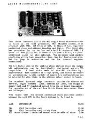
VY·E DATAMAINTENANCE MANUAL<strong>YD</strong>-<strong>380</strong>HALF HEIGHT, HIGH DENSITY, DOUBLE<strong>5.25</strong> INCH FLEXIBLE DISK DRIVESIDEDContents of this manual may be changed without notice.Check the revision number when placing an order.September 1983FDL-523006 REV. A
Revisions---Date.. ~ptember - -Rev. Description Revised Pages83 A First Edition-. -----~ote:I~"('21publication----~e <strong>YD</strong>-<strong>380</strong> may be referred to as simply a "drive".~=~e~ -. disk.<strong>5.25</strong> <strong>inch</strong> flexible disk may be referred to as simply
<strong>YD</strong>-<strong>380</strong> Maintenance ManualTABLE OF CONTENTSPage1.0 INTRODUCTION12.0 MAINTENANCE TOOLS AND TEST EQUIPMENT2.1 Maintenance Tool List2.2 Maintenance Supplies List2.3 Test Equipment2.4 Exerciser112223.0 PREVENTIVE MAINTENANCE3.1 General3.2 Visual Check3.3 Cleaning33334.0 SERVICE CHECKS, REPLACEMENT AND ADJUSTMENT4Maintenance Level 14.1 PWB4.2 Index Sensor Assembly4.3 Track 00 Sensor Assembly4.4 Write Protect Sensor Assembly4.5 Media Sensor Assembly4.6 In Use Lamp Assembly569111214
TABLE OFCONTENTSPage~Aintenance Level. 24.7 Carrier Assembly4.8 Index Lamp Assembly (on Motor Control PWB)4.9 Drive Motor Assembly (on Motor Control PWB)4.10 Head Load Solenoid4.11. Front Lever4.12 Front Bezel4.13 Stepper Assembly4.14 Head/Carriage Assembly1516171821U23245.0 PARTS/ASSEMBLIES PHYSICAL LOCATIONS306.0 TEST POINT/CONNECTOR PIN ASSIGNMENTS35 .7.0 SPARE PARTS LIST388.0 SCHEMATIC DIAGRAMS399.0 EXPLODED VIEW4210.0 USING A CLEANING DISK43
1.0 INTRODUCTIONThis manual describes the maintenance and operation of the Y-EDATA <strong>YD</strong>-<strong>380</strong> two sided, high density, <strong>5.25</strong> <strong>inch</strong> <strong>Floppy</strong> Disk Drive.Included is information on service checks, removal and replacementprocedures, and also adjustment instructions for customers'engineers.2.0 MAINTENANCE TOOLS AND TEST EQUIPMENTThe following tables list the maintenance tools, maintenancesupplies, test equipment and exerciser for the YO-38D.2.1 Maintenance Tools ListTOOLY-E DATE PINPhillips Screwdriver (for M3) 141034-01Phillips Screwdriver (for M2.6) 141627-01Flat Head Screwdriver 141035-01Cutters 141039-01Needle Nose Pliers 141040-01Tweezers 141042-01CE Disk 145173-01Cleaning Disk 145174-01Hex Wrench 1.27 mm 140266-03Hex Wrench 1.5 mm 140266-01
2.2 Maintenance SuppliesSuppliesY-E DATA PINTie Wrap (TY-23M, Kitagawa) 031005-012.3 Test EquipmentTest EquipmentMultimeterElectronic Counter*Oscilloscope** For use at Maintenance Level 22.4 ExerciserEquipmentExerciserY-E DATA PIN<strong>YD</strong>-164T
3 .0 PREVENTIVE MAINTENANCE3.1 GeneralIn a reasonably dust-free environment, preventive maintenanceshould be performed on the <strong>YD</strong>-<strong>380</strong> every two years. Thisincludes a visual check and cleaning.In a dirty environment, the interval between maintenance checksshould be shortened •.3.2 Visual CheckVisual inspection should be the first step in any ma~ntenanceoperation. Always look for corrosion, dirt, wear, binds, andloose connections. Checking for these problems can help reducedowntime later.3.3 CleaningAll cleaning of the <strong>YD</strong>-<strong>380</strong> should be performed carefully.Remove gently all dus~ deposits with lint free gauze or anapplicator moistened with isopropyl alcohol.CAUTIONThe head/carriage assembly is adjusted and tested atthe factory and is not field serviceable. Do not, forany reason, attempt to repair this component.Check Points for Preventive MaintenancePart Check CorrectionFrameConnectorsSensorsMisc.Dirt and dust on the connectors,sensors, other areas.Loose ScrewsCleanTighten
4.0 SERVICE CHECKS, REPLACEMENTS AND ADJUSTMENTSThis chapter contains detailed maintenance procedures for theassemblies listed below. Note that the list is separated intotwo maintenance levels:Levell:Level 2:Can be performed without special training or tools.Special training and tools required.Level 14.1 PWB4.2 Index Sensor4.3 Track 00 Sensor4.4 Write Protect Sensor4.5 Media Sensor4.6 In Use LampLevel 24.7 Carrier4.8 Index Lamp (on Motor Control PWB)4.9 Drive Motor (on Motor Control PWB)4.10 Head Load Solenoid4.11 Front Lever4.12 Front Bezel4.13 Stepper4.14 Head/Carriage AssemblyNote:Refer to Chapter 5 for Parts/Assemblies Locations,Chapter 6 for Test Points/Connector Pin Assignments andChapter 9 for Exploded View.
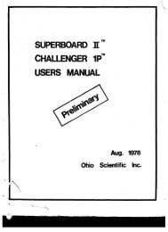
[ Levell]4.1 PWB (Refer to Chapter 5, Figure 1)4.1.1 PWB Replacement1. Disconnect the 4 connectors (J1, J2' J3, J4) from the PWB.2. Remove the four screws securing the PWB to the framecasting.3. Remove the PWB.4. For reinstallation, reverse the above procedure.Note: Make sure to mount the PWB below the carrier cover whenreinstalling.J4 ConnectorJl SignalConnectorJ3 Connectoro,--,I ,, II ,--, :IPWBScrewsScrews (with lock and washer)4-M3 x 6Figure 4.1.1J2 Connector
4.2 Index Sensor Assembly (Refer to Chapter 5, Figure 3)4.2.1 Service Check~1. Power up the drive.2. Without inserting a disk, move the lever to lock positionand check for a to 0.5 V between the PWB connector J3 PinAll and G (GND). Next, insert a disk and close the door;the voltage at the same points should be 2.5 to' <strong>5.25</strong> V'.4.4.2 Replacement1. Remove the PWB (Refer to 4.1)2. Remove J3 connector housing 6. (Refer to Page 9, figure4.2.2)3. Take out the carrier cover screws and remove the carriercover. '4.' Lift, up the lead clamps slightly and pullout the leads.5. Remove the In Use Lamp.6. Take out the screws for the front lever and carrier assembly,and remove the front lever and carrier assembly.7. Take out the screws to the Write Protect Sensor assembly,and as shown in figure 4.4.1, remove the write protectsensor assembly by pushing in the direction indicated.CAUTIONWhen clamping the leads, be careful not to damage thelead insulation.8. For reinstallation, reverse the above procedure.9. Perform a service check. (See 4.l.l)Note:Make sure the front edge of the carrier plate springarm securing the Ready/Off plate does not come incontact with the leads.
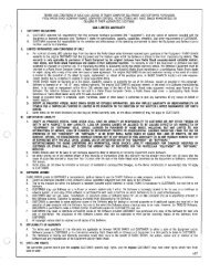
Carrier PlateSpringFront Bezel SideIndex Sensor Screw(with lock and washer,M3 x 6)Collet GuideLead ClampCollet ShaftFigure 4.2.1J3 Connector Housing ~ssignmentConnectorNumber ---t--~Figure 4.2.2ConnectorNo.1 StepperPart2 Head Load Solenoid3 Drive Motor4 Write Protect Sensor5 In Use Lamp6 Index Sensor7 Track 00 Sensor8 Media Sensor
4.2.3 Adjustment1. Loosen the Index Sensor screws one quarter turn.2. Power up the drive.3. Connect an oscilloscope to the PWB test points lA, 1B, 3.Connect channell to PWB TP lA, channel 2 to TP IB, andconnect the external scope trigger to TP3.Set the oscilloscope controls as follows:INPUT COUPLING MODEVERT MODEACADDINVERT (CH 2) ONTIME/DIVVOLTS/DIV (CHI, CH2)0.1 ms100 mV4. Insert a CE Disk and turn the front lever to lock position.5. Load the read/write heads against the disk and step t~ehead/carriage assembly to track 2.Adjust the sensor positionuntil the timing between the start of the sweepsignal from TP3)lA, TP lB)(indexand the first part of the index burst (TPis within -600 to 1400 ~s.,.... ., ,.. 1 _Index Signal (TP3)--------~-600 to 1400~sBurst Signal(TP1A,TP1B)JFigure 4.2.3Note: To delay the Ind~x Burst, move the sensor towards thefront bezel (see Page 9, figure 4.2.1).
6. Verify that the timing between':the start of the sweep andthe first peak of the index burst is between -600 to 1400 ~sat side 0 and 1, track 02 and track 68.4.3 Track 00 Sensor Assembly (Refer to Chapter 5, Figure 4)4.3.1 , Service Check 1, Track 00 Sensor1. Power up the drive.· (Resets memo~ies in PWB)2. Step the head/carriage assembly to a position near theinner stop.3. Check the following:a. Track 00 Lamp:The voltage across PWB J3-A12 and G (GND) should bebetween 1.0 and 1.7 V.b. Track 00 Sensor:The voltage across PWB J3-A13 and G (GND) should bebetween 0 and 0.5 v.4. Power the drive down and up again. (Resets PWB memories)5. Check the following:.a. Track 00 Sensor:The voltage across PWB J3-A13 and G(GND) should be"between 2.5 and <strong>5.25</strong> V.Service Check 2, Track 00 Sensor Position Check1. With power off, move the head/carriage assembly all the wayto the outer stop.2. Power up the drive.3. When power is applied, the head/carriage assembly shouldmove inwards slightly.be at Low level (0 to 0.4 V).The Track 00 signal (Jl-26) should4. Move the head/carriage assembly five steps inward and onestep outward. The voltage should change to a High levelof 2.4 to <strong>5.25</strong> v.
4.3.2 Removal and Replacement1. Remove the PWB (See 4.1).2. Remove J3 connector housing 7. (Refer to page 9, figure4.2.2)3. Cut the J3 cable tie wrap with cutters and remove the Track00 sensor leads from the miniclamp •...---------- CAUTION --------------,Be careful not to damage the leads when cutting the tiewrap.4. Take out the Track 00 sensor assembly screw and remove theassembly.Note:Do not remove the sensor mounting screw or the adjustmentscrew.5. For reinstallation, reverse the above procedure.Note:To attach the Track 00 sensor, push it against theframe stop and tighten the screw.6. Perform service checks 1 and 2.Track 00 SensorScrew (with lockI and washer,M3 x 6)00 SensorFigure 4.3.1Stopable Tie"" Track 00 Mountingscrew
4.4 Write Protect Sensor (See Chapter 5, Figure 3)4.4.1 Service Check1. Power up the drive.2. Check the following with no disk in the drive.a. Write Protect Lamp:The voltage across J3-A8 and G (GND)between 1.0 and 1.7 v.b. Write Protect Sensor:The voltage. across J3-A9 and G (GND)between 0 and 0.5 V.should beshould be3. Check the following with a write protected d~sk (a diskwith a write protect seal over the write protect notch)in the drive and the front lever in lock position.a. Write Protect Sensor:The voltage across J3-A9 and G (GND)between 2.5 and <strong>5.25</strong> V.should be4.4.2 Removal and Replac~ment1. Remove the PWB (See 4.1).2. Remove housing 4 from the J3 connector. (See page 9,figure 4.2.2).3. Remove the carrier cover screws and remove the carrier cover.4. Lift the tabs from the carrier and write protect lead clamps(two locations) and remove the leads.5. Remove the In Use Lamp6. Take out the screws for the front lever, and carrier assembly,and remove the front lever and carrier assembly.
7. Take out the screws to the write protect sensor assembly,and as shown in figure 4.2.2, remove the write protectsensor assembly by pushing in the direction indicated .....---------- CAUTION ----------...,When removing or clamping leads, be careful not todamage the lead insulation.8. For reinstallation~ reverse the above procedure.9. Perform a service check. (See 4.4.1)Write ProtectSensor Assemblylock and washer, M3 x 6)Figure 4.4.14.5 Media Sensor Assembly (Refer to Chapter 5, figure 3)4.5.1 Service Check1. Power up the drive.2. Perform the following with no disk in the drive.a. Check for 1.0 to 1.7 V across PWB J3-A14 and G (GND).b. Check for 0 to 0.5 V across J3-A15 and G (GND).3. Insert a disk and check the following.a. Check for 2.5 to <strong>5.25</strong> V across J3-A15 and G (GND).
4.5.2 Removal and Replacement1. Remove the PWB (See 4.1).2. Remove J3 connector housing 8. (See Page 9, figure 4.2.2)3. Remove the carrier cover screws and the carrier cover.4. Remove the In Use Lamp.5. Remove the media sensor assembly screws and the mediasensor assembly.6. For reinstallation, reverse the above procedure.7. Perform a service check. (See 4.5.1)Note:The media sensor assembly should be attached perpendicula~lyto the frame.Media Sensor AssemblyScrew(with lock andwasher, M3 x 6)Figure 4.4.2
4.6 In Use Lamp (Refer to Chapter 5, Figure 5)4.6.1 Service Check1. Power up the drive.2. Set interface signal DRIVE SELECT 0 to Low level, andinstall a shorting plug on shorting pin DS o.3. The lamp should light up.Note:When the lamp is lit, thl!voltage across J3-AlO andG (GND) should be betweel1 1.0 and 2.0 v.4.6.2 Removal and Replacement1. Remove Housing 5 from the ~JB J3 Connector.2. Remove the In Use Lamp asseIlllb1y screws and remove theIn Use Lamp assembly.3. For reinstallation, reverse the above procedure.4. Perform a service check. (See 4.6.1)
[ Level 2 ]4.7 Carrier Assembly (See Chapter 5, figure 3)4.7.1 Removal and Replacement1. Remove the PWB. (See 4.1)2. Remove the carrier cover screws and remove the carriercover.3. Lift the tabs for the clamps on the carrier assembly and·remove connector housings 1, 2, 3 and 7.4. Remove the front lever screws.and remove the front lever.5. Remove the carrier assembly screws and remove the carrierassembly by pushing towards the rear of the drive. (Seepage 18, figure 4.7.1)6. For reinstallation, reverse the above procedure.Notes: 1) Make sure that the bosses on the carrier fitcorrectly into the matching frame holes whenreattaching the carrier.2) Make su~e that the Ready/Off plate is below thehead arm hanger when reattaching the carrierassembly. (See page 24, figure 4.10.1)
4.8 Index Lamp Assembly4.8.1 Service Check1. Power up the drive.2. Check that the voltage across the PWB J3-A7 and G (GND)is between 1.0 and 1.7 v.4.8.2 Removal and Replacement1. Removal procedure is included in the section on the drivemotor assembly (refer to 4.9.2)Front Lever Screw(M 3 x 3)Carrier Screw(vith l-ock and washer, M3x 8)Ready/Off Plate Screw(with washer,. M 3 x 4)ColletCollet GuideScrew(withwasher, M3x 4)In Use Lamp /Mounting Screw(with lock andwasher. M J x 6)CarrierAssemblyIPosi tioning c::>Boss (back)ClampDrive MotorScrew(Countersink,M3x6)Figure 4.7.1
4.9 Drive Motor Assembly (Refer to Chapter 5, figure 2)4.9.1 Service Check1. Power up the drive.2. Insert a disk and move the front lever to lock position.3. Set the MOTOR ON signal on the interface to Low Level inorder to start the drive motor.4. Load the read/write heads against the disk.5. Connect a counter to TP3 and GND on the PWB.6. Verify that the index pulse period (TP3) is within 166.7 mstl.5% (164.2 to 169.2 ms).____n166.7 ms ~ 1.5% D.... _Figur~ 4.9.1Variable ResistorDrive MotorRotorMotor Control P\lBFigure 4.9.2
4.9.2 Removal and Replacement1. Remove the PWB (See 4.1).2. Remove J3 connector housing 3. (See page 9, figure 4.2.2)3. Remove the carrier assembly. (See page 17, 4.7.1)4. Remove the drive motor screws and remove the motor.5. For reinstallation, reverse the above procedure.6. Perform a service check (See page 20, 4.9.1).4.9.3 Adjustment1. Adjust" the variable resistor on the motor control PWB witha Phillips head screwdriver until the index.period is166.7 ms ±1.5% (refer to figure 4.9.2)4.10. Head Load Solenoid (Refer to Chapter 5, figure 3)4.10.1 Service Check1. Look through the disk inlet on the front bezel to makesure the pad on the bottom of the bail is normal."2. Power up the drive.3. Insert a disk and turn the front lever to lock position.4. Load the read/write heads against the disk.5. Make sure that there i~ a gap between the bail and thecarriage arm throughout the carriage travel.6. Power down the drive.7. Remove the disk and turn the front lever to lock position.8. Look through the disk inlet in the front bezel and verifythat the gap between the unloaded read/write heads iswithin 0.3 to 0.7 nun. If the gap is larger, perform theadjustment described in 4.10.3.
4.10.2 Removal and Replacement1. Remove the PWB (See 4.1).2. Take out the screws attaching the Ready/Off plate to thecarrier assembly and remove the Ready/Off plate.3. Remove J3 connector housing 2. (See page 9. figure 4.2.2)4. Cut the J3 cable tie wrap with cutters and remove theleads from the miniclamp.r---------- CAUTION ----------....,Be careful not to damage the lead insulation whencutting the cable tie wraps.5. Carefully insert a strip of clean paper into the diskslot of the head/carriage assembly from the front bezel.6. Remove the head load solenoid screws. Lift up thecarriage arm hanger slightly with your finger.7. Slide out the solenoid by turning it cloekwise.8. For reinstallation, reverse the above procedure.Note:When reinstalling the head load solenoid, make surethe bail rests under the carriage arm hanger.9. Perform the adjustment on page 24, section 4.10.3.
4.10.3 Adjustment1. Turn the adjusting screw on the Ready/Off plate untilthe gap between the read/write heads is within 0.3 to0.7mm. Turning the screw clockwise increases the gap,counterclockwise decreases it.2. Perform a service check (See 4.10.1)Figure 4.10.1
4.11 Front Lever (Refer to Chapter 5, Figure 5)4.11.1 Removal and Replacement1. Remove the carrier cover.2. Turn the front lever to unlock position.3. Remove the front lever screw with a hex wrench and takethe crankshaft out via the front bezel.CAUTIONBe careful not to lose the washer.4. For reinstallation, reverse the above procedure.Notes: 1) When attaching the front lever, push it againstthe washer before securing.2) Attach the front lever so that the stop screwis even with the slot in the crank shaft.ColleeFront BezelFront Lever Edge~/Stop ScrewFront LeverFigure 4.11.1.
4.12 Front Bezel (Refer to Chapter 5, Figure 5)4.12.1 Removal ahd Replacement1. Remove the carrier cover.2. Remove the front lever stop screw and the front lever.3. Remove the front bezel screws and the front bezel •.4. For reinstallation, reverse the above procedure•.Notes: 1) When reinstalling the front bezel, make sure thatthat the bosses on ·the bezel fit correctlyintb the matching holes in the frame before.securing.2) Refer to section 4.11 for front lever-attachmentinstructions.Front BezelFront Bezel Screw(with lock andwasher, M3x8)Figure 4.12.1PositioningHoles
4.13 Stepper Assembly (Refer to Chapter 5, Figure 3)4.13.1 Service Check1. Power up the drive.2. Check the head/carriage Seek operation by applying theDirection and Step signals t~,the interface~4.13.2 Removal and Replacement1. Remove the PWB. (See 4.1)2. Remove J3 connector housing 1. (See page 9, figure 4.2.2)3. Remove the belt clamp C securing screw' (M2.6) from topof the frame.4. Remove the steel belt assembly screw (M2.6) the top ofthe frame.5. Remove the stepper screw from the frame.6. Gently unloop the steel belt from the stepper.7. For reinstallation, reverse the above procedure.Note: When reinstalling, do not tighten the b~lt clampiand the steel belt assembly screws completely.Move the carriage forward and backward 'with yourhand, making sure that it moves smoothly in bothdirections.secure the screws.If carriage movement is normal,
Head/Carriage AssyInwards.. ~---~.Steel Belt Ass')Screw, (wi thwasher, M2.6 x 4)I..QJ~:r-~I:.'-Belt Clamp CScrew (M2.6x4)Steel Belt AttachmentScrew ( M2.6 x 4)Stepper AssyStepper AttachmentScrew (with specialwasher, M 3x8)Figure 4.13.14.13.3 Adjustment1. Perform the position adjustment for the carriage assembly(see 4.14.3).4.14 Head/Carriage Assembly (Refer to Chapter 5, Figure 3)CAUTIONThe head/carriage assembly is factory adjustedand tested. Never attempt to adjust or repairthis internal component.4.14.1 Radial Alignment Check1. Power up the drive. (Resets the PWB memories)2. Set up a dual trace oscilloscope.- Connect channel 1 to PWB test point lAo
- Connect channel 2 to PWB test point lB.- Connect scope ground to PWB test point G (GND).- Connect the external scope trigger probe to PWB testpoint 3.,Set the oscilloscope controls as follows:INPUT COUPLING MODEVERT MODEACADDINVERT (CH 2) ONTIME/DIV20 msVOLTS/DIV (CH 2) 20 mv3. Insert a CE disk and turn the front lever to lock position.4. Load the read/write heads against the disk and make surethe Track 00 signal (Jl-26) is at Low level (0 to 0.4 V).5. Step the head/carriage from Track 00 to 32. Obtain A/Bor B/A', the ratio between the two amplitude lobes on t·hescope. Convert the ratio to a position on the CE diskconversion chart. The positioning error should be within±25 ~ (See figure 4.14.1, figure 4.14.2).6. Step the head/carriage from track 3) to track 32 and checkthe positioning as in step 5 above.ABFigure 4.14.1
HOW TO USE THE CE DISK AND CONVERSION CHART1. Preparationa) The test should be performed at a temperature of 13°Cto 33°C, and a relative humidity of 20% to 80%.Humidity compensation is. required if the humidity isnot 50%.b) Before using the CE disk, allow a minimum of twohours for the drive (with DC power on) and the diskto adapt to the ambient temperature and humidity ofthe test area.2 • Measurementa) Refer to 4.14.1 for test equipment and set-up procedure.b) Find the pos1t10ning error corresponding to AlB orBfA on the conversion chart printed on the CE diskenvelope.Example:When BIA = 0.9, the conversion chart showsthe positioning error to be +P ~.AlB or BIABIA0.5 AlB0.60.7/0.8.9AlB+P(+)Outer(-)'InnerFigure 4.14.2
c) Compensation (for humidity only)Humidity Compensation Ph = B x (h - 50)Where h is ambient humidity (%RH)B • +0.25 um / %RH = Compensation CoefficientCompensated Positioning ErrorPO • P + Ph • P + 0.25 (h - 50)Example: If h • 70% RH, PO = P + 0.25 (70 - 50)• p + 5 um.4.14.2 Removal and Replacement1. Remove the PWB. (See 4.1)2. Disconnect the J4 connector from the PWB. Remove thehead cable from the groove in the carrier base.3. Take out the Ready/Off plate screws and remove the Ready/Off plate. (See figure 4.10.1)4. Remove the stepper. (See 4.13.2)5. Remove the long guide bar clamps (two locations) andlift out the head/carriage assembly and guide bartogether.6. When reassembling, reverse the above procedure.CAUTIONWhen reinstalling, be careful , not to push on thehead arm hanger of the head/carriage assembly.4.14.3 Position Check1. Make sure the gap between the unloaded read/write headsis within 0.3 to 0.7 mm. (See 4.10.3)
2. Set up a dual trace oscilloscope.Connect channel I to PWB test. point lAo.Connect channel 2 to PWB test point lB.Connect scope ground to PWBtest point G (GND).Connect the external scope trigger probe to PWBpoint 3.testSet the oscilloscope controls as follows:COUPLING MODEVERT MODEACADDINVERT (CH 2) ONTIME/DIV20 msVOLTS/DIV (CH 1, CH 2) 20 mV3. Insert a CE disk and power up the drive.4. Seek the carriage 32 steps inwards.s. Load the read/write heads against the disk. Insert a'screwdriver through the notch in the PWB (figure 4.14.3)and move the. stepper in or out to obtain the positionsignal shown in figure 4.14.1.Note:For this adjustment, tighten the stepper attachmentscrews and then loosen 1/4 turn.Screw .forPositionAdjustmentStepperScrew forPositionAdjustmentFigure 4.14.3
6. In step 5 above, move the stepper according to the following:If A > B move inwardsIf A < B move outwards.7. Obtain A/B or B/A from the side 0 read output and veritythat the position error is within ±25 ~ with the CE diskconversion chart.8. Step the carriage from track 33 to track 32 and make surethe' read output, A/B or B/A, is the same as in step 7.If not, repeat step 6.9. Check that the read output from side one is within thelimits given in steps 7 and 8.10. Perform steps 3 and 4 above to check for the cat's eyesdisplay•. 11. Move the carriage out 32 steps after performing step 10,and verify that the Track 00 signal (Jl - 26) is at Lowlevel.
5.0 PARTS/ASSEMBLES LOCATIONSFRONTBEZELJ4 CONNECTORPWBJl SIGNAL CONNECTOR@UI0008o00 0DOCJ3 CONNECTORPWBSCREWATTACHMENTJ2 CONNECTOR'<strong>YD</strong>-<strong>380</strong>Figure 1Top View
FRAMESTEPPERoooDRIVE MOTORROTORHEAD LOADSOLENOIDYO-<strong>380</strong>Bottom ViewFigure 2
WRITE PROTECTSENSOR ASSYATTACHMENTSCREWJ4READY/OFF PLATE ATTACHMENT SCREWREADY / OFF PLATEHEAD LOAD SOLENOIDHEAD CABLE/ CARRIER ASSYMEDIA SENSOR ASSYHEAD/CARRIAGEASSY CARRIER ASSYATTACHMENT SCREW<strong>YD</strong>-<strong>380</strong> Top View (with PWB removed)Figure 3
HEADCABLEBAILMINI CLAMPoTR 00SENSOR ASSYSPINDLEHTJBSTEEL BELT(with PWB<strong>YD</strong>-<strong>380</strong> Top Viewand carrier assembly removed)Figure 4
IFRONT BEZELIN USEINDICATOR LAMPMOUNTING SCREW TAPS<strong>YD</strong>-<strong>380</strong>Front ViewFigure 5
6.0 TEST POINT/CONNECTOR PIN ASSIGNMENTS (-1710)--~- -- 4.D ~I231:. 500---jD. >'-- _:;10-:·-:'.''''020t1jO L-.~ UtT~~ +~I.S.. CJO ~I~ ~ . ,. I :: 10 -,. -'2"... ••..Jc J2' 4__!.-~
INTERFACE - JlPin No.Signal Name1 RETURN23 RETURN4 HEAD LOAD (IN USE) r5 RETURN6 DRIVE SELECT 37 RETURN8 INDEX9 RETURN10 DRIVE SELECT 011 RETURN12 DRIVE SELECT 113 RETURN14 DRIVE SELECT 215 RETURN16 MOTOR ON17 RE.TURN18 DIRECTION SELECT19 RETURN20- STEP21 RETURN22 WRITE DATA23 RETtIRN24 WRITE GATE25 RETURN26 TRACK 0027 RETURN28 WRITE PROTECT29 RETURN30 READ DATA31 RETURN32 SIDE ONE SELECT33 RETURN34 READY
TRANSDUCER - J3Pi"n No. Signal Name ColorA 1 STEPPER D ORANGEB 1 STEPPER A BLACKA 2 STEPPER (+12V) RED'B 2 STEPPER .B <strong>YE</strong>LLOWA 3 STEPPER (+12V) REDB 3 STEPPER C BROWNA 4 HEAD LOAD SOLENOID(+12V) 'WHITEB 4. HEAD LOAD SOLENOID GREENA 5 DRIVE MOTOR (+12V) REDB 5 DRIVE MOTOR (GND) BLACKA 6 MOTOR ON BLUEB 6 KEY -A 7 INDEX SENSOR LED ORANGEB 7 - -A 8 W/P SENSOR LED <strong>YE</strong>LLOWB 8 KEY -A 9 W/P SENSOR PTK ORANGEB 9 W!P SENSOR RET. BLACKA 1-0 IN USE LED (ANODE) REDB 10 IN USE LED (CATHODE) BLACKA 11 INDEX SENSOR PTK BLUEB 11 INDEX SENSOR PTK RET. BLACKA 12 TRACK 00 SENSOR GREENB 12 TRACK 00 SENSOR LED RET. BLACKA 13 TRACK 00 SENSOR PTK BROWNB 13 TRACK 00 SENSOR PTK RET. BLACKA 14 MEDIA SENSOR LED <strong>YE</strong>LLOWB 14 MEDIA SENSOR RET. BLACKA 15 MEDIA SENSOR PTK BLUEB 15 - -Pin No.A 1B 1A 2B 2A 3B 3A 4B 4A '5B 5A 6B 6A 7B 7Pin No.HEADS - J4Signal NameSHIELD (HEAD 0)SHIELD (HEAD 1)KE<strong>YE</strong>RASE (HEAD 0)ERASE (HEAD 1)W/R ERASE COMMON(HEAD 0)W/R ERASE COMMON(HEAD 1)WlR (HEAD 1)W/R (HEAD 0)W/R (HEAD 1)TEST POINTSSignal NamelA PRE AMP. OUTPUT lAIB PRE AMP. OUTPUT IB2A DIFFERENTIATOR OUTPUT 2A2B DIFFERENTIATOR OUTPUT 2B3 INDEX4 ERASE5 TRACK 00G GROUNDColorREDREDGREENGREENBLACKBLACKWHITE'WHITEPin No.DC - J2Signal Name1 +12V DC2 +12V RETURN3 + 5V RETURN4 + 5V DC
7.0 SPARE PARTS LISTMaintenance Level 1PINPart128012-11 PWB145004-01 Index Sensor Assembly148026-02 Track 00 Sensor Assembly145050-01 Write Protect Sensor Assembly145050-03 Media Sensor Assembly148013-02 In Use Lamp AssemblyMaintenance Level 2PINPart128007-04 Carrier Assembly148085-01 Drive Motor Assembly (on Motor Control PWB)1<strong>380</strong>01-11 Head Load Solenoid135030-01 Front Lever128004-01 Front Bezel-1<strong>380</strong>23-01 Stepper Assembly128026-01 Carriage Assembly
8.0 SCHEMATIC DIAGRAMS1. Revision of schematics is controlled under a revision code,which is printed on both the PWB and the schematics.2. The revision code of the attached schematics"is as follows:Part PIN Drawing Rev.PWB 128012-11 1<strong>380</strong>12-11 BDrive MotorControl PWB148085-01 1<strong>380</strong>61-01 A3. For actual maintenance, use the schematics with the samerevision number as the drive to be serviced.
~,..,-----ote-r- ---11...-3 __5 "--.1-- 11....__.-....;,...... ' - 1I... 5 7 ---L_AII,-,Zy-T, III':srop ~~ ~"'4 ....,f{Jn;~/(,.10II,,, . 1f':9. I elch, ~!i I TI 1 Eo" I"1'/' 47.A. -II2.211:)"8 T~JIf ~C712.,9 1.I, ~Ie I c3 .IC2/f!L~~\Ie, I\lRJ.I{ 1"7 '; ,,(6. a.j ')!.- ~"301('rilei1 I 47;. 11""~I t151720P II115/721 Lru 9_~T12k It .~S S I, 101(Ir]IIIR4 Tcs,)'d..u.IIIII,_44Of".-.IS)' iiK2 ~ 3304 IIZI~ !!!.~",,::,...C3 Lt- d • HZ J-rA.D~J'T I141 13 3 ~ .!. r~ Cf,1RI1'lZ)~/8~ iii. ..iiK ,J~",. ;fe4~(JUA I 1.1,..mil r IITT"'"",II...!-III.~ • II II I 1-777- n'r 11'r -...,l---OItlZ... .!. IJ!O.._.: ~IC:'~al": @'teE> ~r-----------------------------------~III8coE: .~ IIF1>/,02 ---/SsS3:\rPAC<strong>YE</strong>D BY CHECKED BYTRACED BY• e ~. • m• tlI----....----t------------+-----t--------~----f-----+--------------1f.----I---------~IIE\·. 0: IIi DATE 0 It IlUISION DESCIl'PTIOHSICH .,. .. Eeo NO." IIIsnEET•-13E061 - 0/
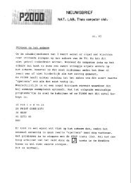
9.0PWB 11P!N 128011-- YIn Use LampPIN 148013-02~~_.!or ~Media se~ . .eJ / iPIN 1450'50~03'..,'"'-'.~ ,'/r; . r ~~ ....~·I~. .~Fron t .Lever~IN 13503~-O"P .",P!N""" .........Fronc bez el ~V ~~128004-01.:)IWrite Protect~.....~ P!N 145050-01W.1j./". cs:Index Sens~rpIN 14.3025-01SensorD~ive Hotor ~___PIN 148085-01
10.0 USING A CLEANING DISK10.1 One of the problems with using different kinds of floppy disksin the field is the build up of magnetic particles on the headsurfaces, which can reduce read/write capability. Two ways toeffectively eliminate this problem are direct cleaning of theheads and proper disk management. Because the structure ofthe heads makes direct cleaning difficult, we recommend using~ cleaning disk.10.2 Recommended Cleaning Disk:Maker:.Model:Nagase SangyoCFD 5W10.3 Head Cleaning Procedure10.3.1 Dirty head surfaces can cause read errors and damage .themagnetic surfece of a disk. If these problems begin to occur,use the cleaning disk to clean the heads.10.3.2 Procedure1. Power up the disk drive and insert the cleaning disk inthe same way as a normal disk.2. Load the read/write heads against the disk.3. In order to increase the effectiveness of the cleaningdisk, the heads should come in contact with as much ofthe disk as possible. Step the carriage in and out duringcleaning.4. One cleaning should take no more than 5 minutes.5. To determine if cleaning is completed, check with aregular disk (new if possible) to see if the read/writefunctions are error free and operating normally.
6. If it appears that cleaning is not complete, repeat steps4 and 5 up to 5 times. When repeating, try to use a newcleaning disk.7. The recommended cleaning disk should have no effect on the<strong>YD</strong>-<strong>380</strong> even after 10 hours of cleaning.8. The ~ife span of the cleaning disk is about one hour ofusage, after which the effect is lost due to silting ofthe disk surface.10.3.3 Head· Cleaning as a Part of Preventive Maintenance1. In order to maintain read/write capability, we recommendthat head cleaning be performed as a part of preventiyemaintenance.2. Cleaning procedure is the same as 10.3.2 above.