Best Practices for SRX Series Chassis Cluster Management
Best Practices for SRX Series Chassis Cluster Management
Best Practices for SRX Series Chassis Cluster Management
- No tags were found...

Create successful ePaper yourself
Turn your PDF publications into a flip-book with our unique Google optimized e-Paper software.
Network Configuration Example<strong>Best</strong> <strong>Practices</strong> <strong>for</strong> <strong>SRX</strong> <strong>Series</strong> <strong>Chassis</strong> <strong>Cluster</strong><strong>Management</strong>Release12.2Published: 2013-02-07Copyright © 2013, Juniper Networks, Inc.
Juniper Networks, Inc.1194 North Mathilda AvenueSunnyvale, Cali<strong>for</strong>nia 94089USA408-745-2000www.juniper.netThis product includes the Envoy SNMP Engine, developed by Epilogue Technology, an Integrated Systems Company. Copyright © 1986-1997,Epilogue Technology Corporation. All rights reserved. This program and its documentation were developed at private expense, and no partof them is in the public domain.This product includes memory allocation software developed by Mark Moraes, copyright © 1988, 1989, 1993, University of Toronto.This product includes FreeBSD software developed by the University of Cali<strong>for</strong>nia, Berkeley, and its contributors. All of the documentationand software included in the 4.4BSD and 4.4BSD-Lite Releases is copyrighted by the Regents of the University of Cali<strong>for</strong>nia. Copyright ©1979, 1980, 1983, 1986, 1988, 1989, 1991, 1992, 1993, 1994. The Regents of the University of Cali<strong>for</strong>nia. All rights reserved.GateD software copyright © 1995, the Regents of the University. All rights reserved. Gate Daemon was originated and developed throughrelease 3.0 by Cornell University and its collaborators. Gated is based on Kirton’s EGP, UC Berkeley’s routing daemon (routed), and DCN’sHELLO routing protocol. Development of Gated has been supported in part by the National Science Foundation. Portions of the GateDsoftware copyright © 1988, Regents of the University of Cali<strong>for</strong>nia. All rights reserved. Portions of the GateD software copyright © 1991, D.L. S. Associates.This product includes software developed by Maker Communications, Inc., copyright © 1996, 1997, Maker Communications, Inc.Juniper Networks, Junos, Steel-Belted Radius, NetScreen, and ScreenOS are registered trademarks of Juniper Networks, Inc. in the UnitedStates and other countries. The Juniper Networks Logo, the Junos logo, and JunosE are trademarks of Juniper Networks, Inc. All othertrademarks, service marks, registered trademarks, or registered service marks are the property of their respective owners.Juniper Networks assumes no responsibility <strong>for</strong> any inaccuracies in this document. Juniper Networks reserves the right to change, modify,transfer, or otherwise revise this publication without notice.Products made or sold by Juniper Networks or components thereof might be covered by one or more of the following patents that areowned by or licensed to Juniper Networks: U.S. Patent Nos. 5,473,599, 5,905,725, 5,909,440, 6,192,051, 6,333,650, 6,359,479, 6,406,312,6,429,706, 6,459,579, 6,493,347, 6,538,518, 6,538,899, 6,552,918, 6,567,902, 6,578,186, and 6,590,785.Network Configuration Example <strong>Best</strong> <strong>Practices</strong> <strong>for</strong> <strong>SRX</strong> <strong>Series</strong> <strong>Chassis</strong> <strong>Cluster</strong> <strong>Management</strong>Release 12.2Copyright © 2013, Juniper Networks, Inc.All rights reserved.The in<strong>for</strong>mation in this document is current as of the date on the title page.YEAR 2000 NOTICEJuniper Networks hardware and software products are Year 2000 compliant. Junos OS has no known time-related limitations through theyear 2038. However, the NTP application is known to have some difficulty in the year 2036.END USER LICENSE AGREEMENTThe Juniper Networks product that is the subject of this technical documentation consists of (or is intended <strong>for</strong> use with) Juniper Networkssoftware. Use of such software is subject to the terms and conditions of the End User License Agreement (“EULA”) posted athttp://www.juniper.net/support/eula.html. By downloading, installing or using such software, you agree to the terms and conditionsof that EULA.iiCopyright © 2013, Juniper Networks, Inc.
Table of ContentsIntroduction . . . . . . . . . . . . . . . . . . . . . . . . . . . . . . . . . . . . . . . . . . . . . . . . . . . . . . . . . 1<strong>Chassis</strong> <strong>Cluster</strong> Overview . . . . . . . . . . . . . . . . . . . . . . . . . . . . . . . . . . . . . . . . . . . . . . 1Hardware Requirements . . . . . . . . . . . . . . . . . . . . . . . . . . . . . . . . . . . . . . . . . . . 1Software Requirements . . . . . . . . . . . . . . . . . . . . . . . . . . . . . . . . . . . . . . . . . . . . 1Control Plane and Data Plane . . . . . . . . . . . . . . . . . . . . . . . . . . . . . . . . . . . . . . 2<strong>Chassis</strong> <strong>Cluster</strong> Descriptions and Deployment Scenarios . . . . . . . . . . . . . . . . . . . . 3Various Deployments of a <strong>Chassis</strong> <strong>Cluster</strong> . . . . . . . . . . . . . . . . . . . . . . . . . . . . . 3Connecting Primary and Secondary Nodes . . . . . . . . . . . . . . . . . . . . . . . . . . . . 6Managing <strong>Chassis</strong> <strong>Cluster</strong>s . . . . . . . . . . . . . . . . . . . . . . . . . . . . . . . . . . . . . . . . 12Configuring Devices <strong>for</strong> In-Band <strong>Management</strong> and Administration . . . . . . . . 13Managing <strong>SRX</strong> <strong>Series</strong> Branch <strong>Chassis</strong> <strong>Cluster</strong>s Through the PrimaryNode . . . . . . . . . . . . . . . . . . . . . . . . . . . . . . . . . . . . . . . . . . . . . . . . . . . . . . 14Communicating with a <strong>Chassis</strong> <strong>Cluster</strong> Device . . . . . . . . . . . . . . . . . . . . . . . . . 17<strong>Best</strong> <strong>Practices</strong> <strong>for</strong> Managing a <strong>Chassis</strong> <strong>Cluster</strong> . . . . . . . . . . . . . . . . . . . . . . . . . . . . 18Using Dual Control Links . . . . . . . . . . . . . . . . . . . . . . . . . . . . . . . . . . . . . . . . . . 18Using Dual Data Links . . . . . . . . . . . . . . . . . . . . . . . . . . . . . . . . . . . . . . . . . . . . 18Using BFD . . . . . . . . . . . . . . . . . . . . . . . . . . . . . . . . . . . . . . . . . . . . . . . . . . . . . . 19Using IP Monitoring . . . . . . . . . . . . . . . . . . . . . . . . . . . . . . . . . . . . . . . . . . . . . . 19Using Interface Monitoring . . . . . . . . . . . . . . . . . . . . . . . . . . . . . . . . . . . . . . . . 19Using Graceful Restart . . . . . . . . . . . . . . . . . . . . . . . . . . . . . . . . . . . . . . . . . . . 20Retrieving <strong>Chassis</strong> Inventory and Interfaces . . . . . . . . . . . . . . . . . . . . . . . . . . . . . . . 21Using the Junos OS XML <strong>Management</strong> Protocol or NETCONF XML<strong>Management</strong> Protocol . . . . . . . . . . . . . . . . . . . . . . . . . . . . . . . . . . . . . . . . 21Using SNMP . . . . . . . . . . . . . . . . . . . . . . . . . . . . . . . . . . . . . . . . . . . . . . . . . . . . 21Identifying Nodes in a <strong>Chassis</strong> <strong>Cluster</strong> . . . . . . . . . . . . . . . . . . . . . . . . . . . . . . . . . . . 23Identifying the <strong>Chassis</strong> <strong>Cluster</strong> Primary and Secondary Nodes . . . . . . . . . . . 23Using the Junos OS XML <strong>Management</strong> Protocol or NETCONF XML<strong>Management</strong> Protocol . . . . . . . . . . . . . . . . . . . . . . . . . . . . . . . . . . . . 23Using the get-chassis-inventory RPC tag . . . . . . . . . . . . . . . . . . . . . . . . . 24Using SNMP . . . . . . . . . . . . . . . . . . . . . . . . . . . . . . . . . . . . . . . . . . . . . . . . 24Determining the IP Address of Nodes . . . . . . . . . . . . . . . . . . . . . . . . . . . . . . . 25Using the Junos OS XML <strong>Management</strong> Protocol or NETCONF XML<strong>Management</strong> Protocol . . . . . . . . . . . . . . . . . . . . . . . . . . . . . . . . . . . . 25Using SNMP MIBs . . . . . . . . . . . . . . . . . . . . . . . . . . . . . . . . . . . . . . . . . . . 26Monitoring Nodes in a <strong>Chassis</strong> <strong>Cluster</strong> . . . . . . . . . . . . . . . . . . . . . . . . . . . . . . . . . . . 27Using the Junos OS XML <strong>Management</strong> Protocol or NETCONF XML<strong>Management</strong> Protocol . . . . . . . . . . . . . . . . . . . . . . . . . . . . . . . . . . . . . . . . 27<strong>Chassis</strong> <strong>Cluster</strong> Redundant Ethernet Interfaces . . . . . . . . . . . . . . . . . . . . . . . 28Using the Junos OS XML <strong>Management</strong> Protocol or NETCONF XML<strong>Management</strong> Protocol . . . . . . . . . . . . . . . . . . . . . . . . . . . . . . . . . . . . 29Using SNMP . . . . . . . . . . . . . . . . . . . . . . . . . . . . . . . . . . . . . . . . . . . . . . . . 33Copyright © 2013, Juniper Networks, Inc.iii
<strong>Best</strong> <strong>Practices</strong> <strong>for</strong> <strong>SRX</strong> <strong>Series</strong> <strong>Chassis</strong> <strong>Cluster</strong> <strong>Management</strong>Using the Control Plane . . . . . . . . . . . . . . . . . . . . . . . . . . . . . . . . . . . . . . . . . . 34Using the Junos OS XML <strong>Management</strong> Protocol or NETCONF XML<strong>Management</strong> Protocol . . . . . . . . . . . . . . . . . . . . . . . . . . . . . . . . . . . . 34Using the Data Plane . . . . . . . . . . . . . . . . . . . . . . . . . . . . . . . . . . . . . . . . . . . . 34Using the Junos OS XML <strong>Management</strong> Protocol or NETCONF XML<strong>Management</strong> Protocol . . . . . . . . . . . . . . . . . . . . . . . . . . . . . . . . . . . . 34Using SNMP . . . . . . . . . . . . . . . . . . . . . . . . . . . . . . . . . . . . . . . . . . . . . . . . 35Provisioning <strong>Chassis</strong> <strong>Cluster</strong> Nodes . . . . . . . . . . . . . . . . . . . . . . . . . . . . . . . . . 35Monitoring <strong>Chassis</strong> <strong>Cluster</strong> Per<strong>for</strong>mance . . . . . . . . . . . . . . . . . . . . . . . . . . . . . . . . 36Monitoring <strong>Chassis</strong> <strong>Cluster</strong> Per<strong>for</strong>mance . . . . . . . . . . . . . . . . . . . . . . . . . . . . . 38Redundant Group Monitoring . . . . . . . . . . . . . . . . . . . . . . . . . . . . . . . . . . . . . . 38Interface Statistics . . . . . . . . . . . . . . . . . . . . . . . . . . . . . . . . . . . . . . . . . . . . . . 38Services Processing Unit Monitoring . . . . . . . . . . . . . . . . . . . . . . . . . . . . . . . . 39Junos OS XML RPC Instrumentation <strong>for</strong> SPU Monitoring . . . . . . . . . . . . 39SNMP MIB Instrumentation <strong>for</strong> SPU Monitoring . . . . . . . . . . . . . . . . . . . . 41Security Features . . . . . . . . . . . . . . . . . . . . . . . . . . . . . . . . . . . . . . . . . . . . . . . 42Other Statistics and MIBS . . . . . . . . . . . . . . . . . . . . . . . . . . . . . . . . . . . . . . . . 44RMON . . . . . . . . . . . . . . . . . . . . . . . . . . . . . . . . . . . . . . . . . . . . . . . . . . . . . . . . 44<strong>Chassis</strong> <strong>Cluster</strong> Device Health Monitoring . . . . . . . . . . . . . . . . . . . . . . . . . . . . 45Monitoring <strong>Chassis</strong> <strong>Cluster</strong> Faults . . . . . . . . . . . . . . . . . . . . . . . . . . . . . . . . . . . . . . 45SNMP Traps . . . . . . . . . . . . . . . . . . . . . . . . . . . . . . . . . . . . . . . . . . . . . . . . . . . 46System Log Messages . . . . . . . . . . . . . . . . . . . . . . . . . . . . . . . . . . . . . . . . . . . . 72Failover Trap . . . . . . . . . . . . . . . . . . . . . . . . . . . . . . . . . . . . . . . . . . . . . . . . . . . 74Other Indications <strong>for</strong> Failover . . . . . . . . . . . . . . . . . . . . . . . . . . . . . . . . . . . . . . 77Managing and Monitoring a <strong>Chassis</strong> <strong>Cluster</strong> Using Operational and EventScripts . . . . . . . . . . . . . . . . . . . . . . . . . . . . . . . . . . . . . . . . . . . . . . . . . . . . 78Using the Utility MIB <strong>for</strong> Monitoring a <strong>Chassis</strong> <strong>Cluster</strong> . . . . . . . . . . . . . . . . . . . 79Log Messages <strong>for</strong> <strong>SRX</strong> <strong>Series</strong> <strong>Chassis</strong> <strong>Cluster</strong>s . . . . . . . . . . . . . . . . . . . . . . . . . . . 80Sessions and Packet Flows Overview . . . . . . . . . . . . . . . . . . . . . . . . . . . . . . . 80Configuring High-End <strong>SRX</strong> <strong>Series</strong> Device Logging . . . . . . . . . . . . . . . . . . . . . . 81Configuring High-End <strong>SRX</strong> <strong>Series</strong> Device Data Plane Logging to the ControlPlane . . . . . . . . . . . . . . . . . . . . . . . . . . . . . . . . . . . . . . . . . . . . . . . . . . . . . 82Configuring <strong>SRX</strong> <strong>Series</strong> Branch Devices to Send Traffic Log MessagesThrough the Data Plane . . . . . . . . . . . . . . . . . . . . . . . . . . . . . . . . . . . . . . 82Configuring Control Plane Logs . . . . . . . . . . . . . . . . . . . . . . . . . . . . . . . . . . . . 84Configuring Branch <strong>SRX</strong> <strong>Series</strong> Devices <strong>for</strong> Logging . . . . . . . . . . . . . . . . . . . . 85Sending Data Plane Log Messages with an IP Address in the Same Subnetas the fxp0 Interface . . . . . . . . . . . . . . . . . . . . . . . . . . . . . . . . . . . . . . . . . 86Tracking Applications on an <strong>SRX</strong> <strong>Series</strong> <strong>Chassis</strong> <strong>Cluster</strong> . . . . . . . . . . . . . . . . . . . . 87Managing <strong>SRX</strong> <strong>Series</strong> <strong>Chassis</strong> <strong>Cluster</strong>s Using RPCs . . . . . . . . . . . . . . . . . . . . . . . . 87Managing <strong>SRX</strong> <strong>Series</strong> <strong>Chassis</strong> <strong>Cluster</strong>s Using SNMP . . . . . . . . . . . . . . . . . . . . . . . 92Event Script <strong>for</strong> Generating <strong>Chassis</strong> <strong>Cluster</strong> SNMP Traps . . . . . . . . . . . . . . . . . . . 95Utility MIB Examples . . . . . . . . . . . . . . . . . . . . . . . . . . . . . . . . . . . . . . . . . . . . . . . . 96ivCopyright © 2013, Juniper Networks, Inc.
Introduction<strong>Chassis</strong> <strong>Cluster</strong> OverviewThis document provides the best practices and methods <strong>for</strong> monitoring high-end <strong>SRX</strong><strong>Series</strong> chassis clusters using instrumentation available in the Junos ® operating system(Junos OS) such as SNMP, the NETCONF XML management protocol, and syslog. Thisdocument is applicable to all high-end <strong>SRX</strong> <strong>Series</strong> Services Gateways.A chassis cluster provides high redundancy. Be<strong>for</strong>e you begin managing an <strong>SRX</strong> <strong>Series</strong>chassis cluster, you need to have a basic understanding of how the cluster is <strong>for</strong>med andhow it works.<strong>Chassis</strong> cluster functionality includes:• A resilient system architecture, with a single active control plane <strong>for</strong> the entire clusterand multiple Packet Forwarding Engines. This architecture presents a single deviceview of the cluster.• Synchronization of configuration and dynamic runtime states between nodes withina cluster.• Monitoring of physical interfaces and failover if the failure parameters cross a configuredthreshold.To <strong>for</strong>m a chassis cluster, a pair of the same model of supported <strong>SRX</strong> <strong>Series</strong> devices arecombined to act as a single system that en<strong>for</strong>ces the same overall security. <strong>Chassis</strong>cluster <strong>for</strong>mation depends on the model. For <strong>SRX</strong>3400 and <strong>SRX</strong>3600 chassis clusters,the location and type of Services Processing Cards (SPCs), I/O cards (IOCs), and NetworkProcessing Cards (NPCs) must match in the two devices. For <strong>SRX</strong>5600 and <strong>SRX</strong>5800chassis clusters, the placement and type of SPCs must match in the two clusters.An <strong>SRX</strong> <strong>Series</strong> chassis cluster is created by physically connecting two identicalcluster-supported <strong>SRX</strong> <strong>Series</strong> devices using a pair of the same type of Ethernetconnections. The connection is made <strong>for</strong> both a control link and a fabric (data) linkbetween the two devices.Hardware RequirementsThis following hardware components are required to support chassis clusters:• <strong>SRX</strong>1400, <strong>SRX</strong>3400, <strong>SRX</strong>3600, <strong>SRX</strong>5600, or <strong>SRX</strong>5800 Services Gateways• <strong>SRX</strong>100, <strong>SRX</strong>200, or <strong>SRX</strong>600 <strong>Series</strong> branch devicesSoftware RequirementsThis following software components are required to support chassis clusters:• Junos OS Release 9.5 or laterCopyright © 2013, Juniper Networks, Inc.1
<strong>Best</strong> <strong>Practices</strong> <strong>for</strong> <strong>SRX</strong> <strong>Series</strong> <strong>Chassis</strong> <strong>Cluster</strong> <strong>Management</strong>• Junos OS Release 10.1R2 or later <strong>for</strong> <strong>SRX</strong> <strong>Series</strong> branch device virtual chassismanagement and in-band managementFor more in<strong>for</strong>mation about how to <strong>for</strong>m clusters, see the Junos OS Security ConfigurationGuide.Control Plane and Data PlaneWhen creating a chassis cluster, the control ports on the respective nodes are connectedto <strong>for</strong>m a control plane that synchronizes configuration and kernel state to facilitate thechassis clustering of interfaces and services. The data planes on the respective nodesare connected over the fabric ports to <strong>for</strong>m a unified data plane.The control plane software operates in active/backup mode. When configured as achassis cluster, the two nodes back up each other, with one node acting as the primarydevice and the other as the secondary device, ensuring stateful failover of processes andservices in the event of a system or hardware failure. If the primary device fails, thesecondary device takes over processing the traffic.The data plane software operates in active/active mode. In a chassis cluster, sessionin<strong>for</strong>mation is updated as traffic traverses either device, and this in<strong>for</strong>mation is transmittedbetween the nodes over the fabric link to guarantee that established sessions are notdropped when a failover occurs. In active/active mode, it is possible <strong>for</strong> traffic to ingressthe cluster on one node and egress the cluster from the other node.When a device joins a cluster, it becomes a node of that cluster. With the exception ofunique node settings and management IP addresses, nodes in a cluster share the sameconfiguration.You can deploy up to 15 chassis clusters in a Layer 2 domain. <strong>Cluster</strong>s and nodes areidentified in the following ways:• A cluster is identified by a cluster ID (cluster-id) specified as a number from 1 through15.• A cluster node is identified by a node ID (node) specified as a number from 0 to 1.<strong>Chassis</strong> clustering of interfaces and services is provided through redundancy groups andprimacy within groups. A redundancy group is an abstract construct that includes andmanages a collection of objects. A redundancy group contains objects on both nodes. Aredundancy group is primary on one node and backup on the other at any time. When aredundancy group is said to be primary on a node, its objects on that node are active. Seethe Junos OS Security Configuration Guide <strong>for</strong> detailed in<strong>for</strong>mation about redundancygroups. Redundancy groups are the concept in Junos OS Services Redundancy Protocol(JSRP) clustering that is similar to a virtual security interface (VSI) in Juniper NetworksScreenOS ® Software. Basically, each node has an interface in the redundancy group,where only one interface is active at a time. A redundancy group is a concept similar toa virtual security device (VSD) in ScreenOS Software. Redundancy group 0 is always <strong>for</strong>the control plane, while redundancy group 1+ is always <strong>for</strong> the data plane ports.RelatedDocumentation• <strong>Chassis</strong> <strong>Cluster</strong> Descriptions and Deployment Scenarios on page 32Copyright © 2013, Juniper Networks, Inc.
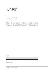
• <strong>Best</strong> <strong>Practices</strong> <strong>for</strong> Managing a <strong>Chassis</strong> <strong>Cluster</strong> on page 18<strong>Chassis</strong> <strong>Cluster</strong> Descriptions and Deployment Scenarios• Various Deployments of a <strong>Chassis</strong> <strong>Cluster</strong> on page 3• Connecting Primary and Secondary Nodes on page 6• Managing <strong>Chassis</strong> <strong>Cluster</strong>s on page 12• Configuring Devices <strong>for</strong> In-Band <strong>Management</strong> and Administration on page 13• Managing <strong>SRX</strong> <strong>Series</strong> Branch <strong>Chassis</strong> <strong>Cluster</strong>s Through the Primary Node on page 14• Communicating with a <strong>Chassis</strong> <strong>Cluster</strong> Device on page 17Various Deployments of a <strong>Chassis</strong> <strong>Cluster</strong>Firewall deployments can be active/passive or active/active.Active/passive chassis cluster mode is the most common type of chassis cluster firewalldeployment and consists of two firewall members of a cluster. One actively providesrouting, firewall, NAT, virtual private network (VPN), and security services, along withmaintaining control of the chassis cluster. The other firewall passively maintains its state<strong>for</strong> cluster failover capabilities should the active firewall become inactive.<strong>SRX</strong> <strong>Series</strong> devices support the active/active chassis cluster mode <strong>for</strong> environments inwhich you want to maintain traffic on both chassis cluster members whenever possible.In an <strong>SRX</strong> <strong>Series</strong> device active/active deployment, only the data plane is in active/activemode, while the control plane is actually in active/passive mode. This allows one controlplane to control both chassis members as a single logical device, and in case of controlplane failure, the control plane can fail over to the other unit. This also means that thedata plane can fail over independently of the control plane. Active/active mode alsoallows <strong>for</strong> ingress interfaces to be on one cluster member, with the egress interface onthe other. When this happens, the data traffic must pass through the data fabric to goto the other cluster member and out of the egress interface. This is known as Z mode.Active/active mode also allows the routers to have local interfaces on individual clustermembers that are not shared among the cluster in failover, but rather only exist on asingle chassis. These interfaces are often used in conjunction with dynamic routingprotocols that fail traffic over to the other cluster member if needed. Figure 1 on page 4shows two <strong>SRX</strong>5800 devices in a cluster.Copyright © 2013, Juniper Networks, Inc.3
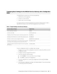
<strong>Best</strong> <strong>Practices</strong> <strong>for</strong> <strong>SRX</strong> <strong>Series</strong> <strong>Chassis</strong> <strong>Cluster</strong> <strong>Management</strong>Figure 1: <strong>SRX</strong>5800 Devices in a <strong>Cluster</strong>Node 0 Node 1Control port 0fpc 3, port 0Control port 0fpc 15, port 0Control port 1fpc 18, port 1Control port 1fpc 6, port 1Fiber-opticcableg030658To effectively manage the <strong>SRX</strong> clusters, network management applications must do thefollowing:• Identify and monitor primary and secondary nodes• Monitor redundancy groups and interfaces• Monitor control and data planes• Monitor switchovers and failuresFigure 2 on page 5 shows the <strong>SRX</strong> <strong>Series</strong> high-end devices configuration <strong>for</strong> out-of-bandmanagement and administration.4Copyright © 2013, Juniper Networks, Inc.
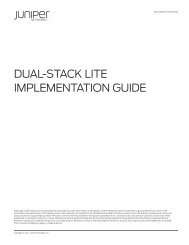
Figure 2: <strong>SRX</strong> <strong>Series</strong> High-End <strong>Chassis</strong> <strong>Cluster</strong> Setup Connecting to a<strong>Management</strong> Station Through a Backup RouterNM SoftwareBackup Routerfxp0/rethfxp0/rethSNMP, NETCONF, Junos XML <strong>Management</strong> Protocol,Syslog, Session Logs, J-Web, CLIControlDataPrimary<strong>SRX</strong> High-End <strong>Cluster</strong>Secondaryg041312Figure 3 on page 6 shows the <strong>SRX</strong> <strong>Series</strong> branch devices configuration <strong>for</strong> out-of-bandmanagement and administration.Copyright © 2013, Juniper Networks, Inc.5
<strong>Best</strong> <strong>Practices</strong> <strong>for</strong> <strong>SRX</strong> <strong>Series</strong> <strong>Chassis</strong> <strong>Cluster</strong> <strong>Management</strong>Figure 3: Branch <strong>SRX</strong> <strong>Series</strong> <strong>Cluster</strong> Setup Connecting to a <strong>Management</strong>Station Through a Backup RouterNM SoftwareBackup Routerfxp0/rethfxp0/rethSNMP, NETCONF, Junos XML <strong>Management</strong> Protocol,Syslog, Session Logs, J-Web, CLIControlPrimaryData<strong>SRX</strong> Branch <strong>Cluster</strong>Secondaryg041313Connecting Primary and Secondary NodesThe following is the best configuration to connect to the cluster from managementsystems. This configuration ensures that the management system is able to connect toboth primary and secondary nodes.user@host# show groupsnode0 {system {host-name <strong>SRX</strong>3400-1;backup-router 172.19.100.1 destination 10.0.0.0/8;services {outbound-ssh {client nm-10.200.0.1 {device-id A9A2F7;secret "$9$T3Ct0BIEylIRs24JDjO1IRrevWLx-VeKoJUDkqtu0BhS"; ##SECRET-DATAservices netconf;10.200.0.1 port 7804;}}}syslog {file messages {any notice;structured-data;}}6Copyright © 2013, Juniper Networks, Inc.
}interfaces {fxp0 {unit 0 {family inet {address 172.19.100.164/24;}}}}}node1 {system {host-name <strong>SRX</strong>3400-2;backup-router 172.19.100.1 destination 10.0.0.0/8;services {outbound-ssh {client nm-10.200.0.1 {device-id F007CC;secret "$9$kPFn9ApOIEAtvWXxdVfTQzCt0BIESrIR-VsYoa9At0Rh"; ##SECRET-DATAservices netconf;10.200.0.1 port 7804;}}}}}# The following syslog configuration is not applicable <strong>for</strong> Branch <strong>SRX</strong><strong>Series</strong> Services Gateways:syslog {file default-log-messages {any notice;structured-data;}}interfaces {fxp0 {unit 0 {family inet {address 172.19.100.165/24;}}}}user@host# show apply-groupsapply-groups "${node}";{primary:node0} [edit]user@host# show interfacesinterfaces {fxp0 {unit 0 {family inet {Copyright © 2013, Juniper Networks, Inc.7
ead-view all;}}}}}}target-address petserver {address 116.197.178.20;tag-list router1;routing-instance MGMT_10;target-parameters test;}target-parameters test {parameters {message-processing-model v3;security-model usm;security-level authentication;security-name juniper;}notify-filter filter1;}notify server {type trap;tag router1;}notify-filter filter1 {oid .1 include;}}{primary:node0}[edit]user@host# show routing-optionsstatic {route 10.200.0.1/32 next-hop 172.19.100.1;}primary:node0}[edit]root@<strong>SRX</strong>3400-1# show firewallterm permit-ssh {from {source-address {10.200.0.0/24;}protocol tcp;destination-port [ ssh telnet ];}then accept;}term permit-udp {from {source-address {207.17.137.28/32;}protocol udp;}then accept;Copyright © 2013, Juniper Networks, Inc.9
<strong>Best</strong> <strong>Practices</strong> <strong>for</strong> <strong>SRX</strong> <strong>Series</strong> <strong>Chassis</strong> <strong>Cluster</strong> <strong>Management</strong>}term permit-icmp {from {protocol icmp;icmp-type [ echo-reply echo-request ];}then accept;}term permit-ntp {from {source-address {149.20.68.16/32;}protocol udp;port ntp;}then accept;}term permit-ospf {from {protocol ospf;}then accept;}term permit-snmp {from {source-address {10.200.0.0/24;}protocol udp;port [ snmp snmptrap ];}then accept;}term deny-and-count {from {source-address {0.0.0.0/0;}}then {count denied;reject tcp-reset;}}}Explanation of Configuration• The best way to connect to an <strong>SRX</strong> <strong>Series</strong> chassis cluster through the fxp0 interface(a new type of interface) is to assign IP addresses to both management ports on theprimary and secondary nodes using groups.• Use a master-only IP address across the cluster. This way, you can query a single IPaddress and that IP address is always the master <strong>for</strong> redundancy group 0. If you are10Copyright © 2013, Juniper Networks, Inc.
not using a master-only IPv4 address, each node IP address must be added andmonitored. Secondary node monitoring is limited, as detailed in this topic.NOTE: We recommend using a master-only IPv4 address <strong>for</strong> management,especially while using SNMP. This enables the device to be reachable evenafter failover.• With the fxp0 interface configuration previously shown, the management IPv4 addresson the fxp0 interface of the secondary node in a chassis cluster is not reachable. Thesecondary node routing subsystem is not running. The fxp0 interface is reachable byhosts that are on the same subnet as the management IPv4 address. If the host is ona different subnet than the management IPv4 address, then communication fails. Thisis an expected behavior and works as designed. The secondary cluster member’sRouting Engine is not operational until failover. The routing protocol process does notwork in the secondary node when the primary node is active. When managementaccess is needed, the backup-router configuration statement can be used.With the backup-router statement, the secondary node can be accessed from anexternal subnet <strong>for</strong> management purposes. Due to a system limitation, do not configurethe destination address specified in the backup-router as ‘0.0.0.0/0’ or ‘::/0’. The maskhas to be a non-zero value. Multiple destinations can be included if your managementIP address range is not contiguous. In this example, backup router 172.19.100.1 isreachable through the fxp0 interface, and the destination network management systemIPv4 address is 10.200.0.1. The network management address is reachable throughthe backup router. For the backup router to reach the network management system,include the destination subnet in the backup router configuration.• We recommend using the outbound SSH address to connect to the managementsystems by using the SSH protocol, NETCONF XML management protocol, or JunosOS XML <strong>Management</strong> Protocol. This ensures that the device connects backautomatically even after a switchover.• We recommend using different SNMP engine IDs <strong>for</strong> each node. This is because SNMPv3uses the SNMP engine boots value <strong>for</strong> authentication of the protocol data units (PDUs),and the SNMP engine boots value is different <strong>for</strong> each node. SNMPv3 might fail aftera switchover when the SNMP engine boots value does not match the expected value.Most of the protocol stacks will resynchronize if the SNMP engine IDs are different.• Keep other SNMP configurations, such as the SNMP communities, trap-groups, andso on, common between the nodes as shown in the sample configuration.NOTE: SNMP traps are sent only from the primary node. This includesevents and failures detected on the secondary node. The secondary nodenever sends SNMP traps or alerts. Use the client-only configurable optionto restrict SNMP access to the required clients only. Use SNMPv3 <strong>for</strong>encryption and authentication.• Syslog messages should be sent from both nodes separately as the log messages arenode specific.Copyright © 2013, Juniper Networks, Inc.11
<strong>Best</strong> <strong>Practices</strong> <strong>for</strong> <strong>SRX</strong> <strong>Series</strong> <strong>Chassis</strong> <strong>Cluster</strong> <strong>Management</strong>• If the management station is on a different subnet than the management IP addresses,specify the same subnet in the backup router configuration and add a static routeunder the [edit routing-options] hierarchy level if required. In the previous sampleconfiguration, the network management address 10.200.0.1 is reachable through thebackup router. There<strong>for</strong>e, a static route is configured.• You can restrict access to the device using firewall filters. The previous sampleconfiguration shows that SSH, SNMP, and Telnet are restricted to the 10.0.0.0/8network. This configuration allows UDP, ICMP, OSPF, and NTP traffic and denies othertraffic. This filter is applied to the fxp0 interface.• You can also use security zones to restrict the traffic. For more in<strong>for</strong>mation, see theJunos OS Security Configuration Guide.Additional Configuration <strong>for</strong> <strong>SRX</strong> <strong>Series</strong> Branch Devices• The factory default configuration <strong>for</strong> the <strong>SRX</strong>100, <strong>SRX</strong>210, and <strong>SRX</strong>240 devicesautomatically enables Layer 2 Ethernet switching. Because Layer 2 Ethernet switchingis not supported in chassis cluster mode, <strong>for</strong> these devices, if you use the factory defaultconfiguration, you must delete the Ethernet switching configuration be<strong>for</strong>e you enablechassis clustering.• There is no dedicated fxp0 management interface. The fxp0 interface is repurposedfrom a built-in interface. For example, on <strong>SRX</strong>100 devices, the fe-0/0/06 interface isrepurposed as the management interface and is automatically renamed fxp0. Formore in<strong>for</strong>mation about the management interface, see the Junos OS SecurityConfiguration Guide.• Syslog should be used with caution. It can cause cluster instability. Data plane loggingshould never be sent through syslogs <strong>for</strong> <strong>SRX</strong> <strong>Series</strong> Branch devices.Managing <strong>Chassis</strong> <strong>Cluster</strong>s• Managing chassis clusters through redundant Ethernet interfaces—<strong>SRX</strong> <strong>Series</strong> chassisclusters can be managed using the redundant Ethernet (reth) interfaces. Configurationof redundancy groups and reth interfaces differ based on deployments such asactive/active mode and active/passive mode. See the Junos OS Security ConfigurationGuide <strong>for</strong> details of the configuration. Once the reth interfaces are configured and arereachable from the management station, secondary nodes can be accessed throughthe reth interfaces.If the reth interface belongs to redundancy group 1+, then the TCP connection to themanagement station is seamlessly transitioned to the new primary. But if redundancygroup 0 failover occurs and the Routing Engine switches over to a new node, thenconnectivity is lost <strong>for</strong> all sessions <strong>for</strong> a couple of seconds.• Managing clusters through the transit interfaces—<strong>Cluster</strong>ed devices can be managedusing transit interfaces. A transit interface cannot be used directly to reach a secondarynode.12Copyright © 2013, Juniper Networks, Inc.
Configuring Devices <strong>for</strong> In-Band <strong>Management</strong> and AdministrationThe chassis cluster feature available in Junos OS <strong>for</strong> <strong>SRX</strong> <strong>Series</strong> Services Gateways ismodeled based on the redundancy features found in Junos OS-based devices. Designedwith separate control and data planes, Junos OS-based devices provide redundancy inboth planes. The control plane in Junos OS is managed by the Routing Engines, whichper<strong>for</strong>m all the routing and <strong>for</strong>warding computations apart from other functions. Oncethe control plane converges, <strong>for</strong>warding entries are pushed to all Packet ForwardingEngines in the system. Packet Forwarding Engines then per<strong>for</strong>m route-based lookups todetermine the appropriate destination <strong>for</strong> each packet without any intervention from theRouting Engines.When enabling a chassis cluster in an <strong>SRX</strong> <strong>Series</strong> Services Gateway, the same modeldevice is used to provide control plane redundancy as shown in Figure 4 on page 13.Figure 4: <strong>SRX</strong> <strong>Series</strong> <strong>Cluster</strong>ing ModelNSR/GR Provide Nonstop FailoverControl PlaneDaemonsNode 0em0em1Control PlaneDaemonsNode 1Node 0 Node 1ForwardingDaemonsNode 0fab0fab1ForwardingDaemonsNode 1ControlPlaneDataPlaneg041314Similar to a device with two Routing Engines, the control plane of an <strong>SRX</strong> <strong>Series</strong> clusteroperates in an active/passive mode with only one node actively managing the controlplane at any given time. Because of this, the <strong>for</strong>warding plane always directs all trafficsent to the control plane (also referred to as host-inbound traffic) to the cluster’s primarynode. This traffic includes (but is not limited to):• Traffic <strong>for</strong> the routing processes, such as BGP, OSPF, IS-IS, RIP, and PIM traffic• IKE negotiation messages• Traffic directed to management processes, such as SSH, Telnet, SNMP, and NETCONF• Monitoring protocols, such as BFD or RPMThis behavior applies only to host-inbound traffic. Through traffic (that is, traffic <strong>for</strong>wardedby the cluster, but not destined to any of the cluster’s interfaces) can be processed byeither node, based on the cluster’s configuration.Because the <strong>for</strong>warding plane always directs host-inbound traffic to the primary node,the fxp0 interface provides an independent connection to each node, regardless of theCopyright © 2013, Juniper Networks, Inc.13
<strong>Best</strong> <strong>Practices</strong> <strong>for</strong> <strong>SRX</strong> <strong>Series</strong> <strong>Chassis</strong> <strong>Cluster</strong> <strong>Management</strong>status of the control plane. Traffic sent to the fxp0 interface is not processed by the<strong>for</strong>warding plane, but is sent to the Junos OS kernel, thus providing a way to connect tothe control-plane of a node, even on the secondary node.This topic explains how to manage a chassis cluster through the primary node withoutrequiring the use of the fxp0 interfaces, that is, in-band management. This is particularlyneeded <strong>for</strong> <strong>SRX</strong> <strong>Series</strong> branch devices since the typical deployment <strong>for</strong> these devices issuch that there is no management network available to monitor the remote branch office.Be<strong>for</strong>e Junos OS Release 10.1 R2, the management of an <strong>SRX</strong> <strong>Series</strong> branch chassiscluster required connectivity to the control plane of both members of the cluster, therebyrequiring access to the fxp0 interface of each node. In Junos OS Release 10.1 R2 and later,<strong>SRX</strong> <strong>Series</strong> branch devices can be managed remotely using the reth interfaces or theLayer 3 interfaces.Managing <strong>SRX</strong> <strong>Series</strong> Branch <strong>Chassis</strong> <strong>Cluster</strong>s Through the Primary NodeAccessing the primary node of a cluster is as easy as establishing a connection to any ofthe node’s interfaces (other than the fxp0 interface). Layer 3 and reth interfaces alwaysdirect the traffic to the primary node, whichever node that is. Both deployment scenariosare common and are depicted in Figure 5 on page 15 and Figure 6 on page 16.In both cases, establishing a connection to any of the local addresses connects to theprimary node. To be precise, you are connected to the primary node of redundancy group0. For example, you can connect to the primary node even when the reth interface, amember of the redundancy group 1, is active in a different node (the same applies toLayer 3 interfaces, even if they physically reside in the backup node). You can use SSH,Telnet, SNMP, or the NETCONF XML management protocol to monitor the <strong>SRX</strong> chassiscluster.Figure 5 on page 15 shows an example of an <strong>SRX</strong> <strong>Series</strong> branch device being managedover a reth interface. This model can be used <strong>for</strong> <strong>SRX</strong> <strong>Series</strong> high-end devices as well,using Junos OS Release 10.4 or later.14Copyright © 2013, Juniper Networks, Inc.
Figure 5: <strong>SRX</strong> <strong>Series</strong> Branch Deployment <strong>for</strong> In-Band <strong>Management</strong> Usinga reth InterfaceBranch OfficeEX SwitchEX Switch<strong>SRX</strong> <strong>Cluster</strong>EX SwitchRETH1.0Redundant Ethernetinterface connectedto the InternetINTERNETRETH0.0Redundant Ethernetinterface connectedto the trusted networkg041315Figure 6 on page 16 shows physical connections <strong>for</strong> in-band management using a Layer3 interface.Copyright © 2013, Juniper Networks, Inc.15
<strong>Best</strong> <strong>Practices</strong> <strong>for</strong> <strong>SRX</strong> <strong>Series</strong> <strong>Chassis</strong> <strong>Cluster</strong> <strong>Management</strong>Figure 6: <strong>SRX</strong> <strong>Series</strong> Branch Deployment <strong>for</strong> In-Band <strong>Management</strong> Usinga Layer 3 InterfaceBranch OfficeEX SwitchEX Switch<strong>SRX</strong> <strong>Cluster</strong>L3 Interfacesge-0/0/0.0 interfaceconnected to theInternetINTERNETRETH0.0Redundant Ethernetinterface connectedto the trusted networkg041316NOTE: If there is a failover, only in-band connections need to be able to reachthe new primary node through the reth or Layer 3 interfaces to maintainconnectivity between the management station and the cluster.Table 1 on page 16 lists the advantages and disadvantages of using different interfaces.Table 1: Advantages and Disadvantages of Different Interfacesfxp0 InterfaceReth and Transit InterfacesUsing the fxp0 interface with a master-only IP address allowsaccess to all routing instances and virtual routers within thesystem. The fxp0 interface can only be part of the inet.0 routingtable. Since the inet.0 routing table is part of the default routinginstance, it can be used to access data <strong>for</strong> all routing instancesand virtual routers.A transit or reth interface has access only to the data of therouting instance or virtual router it belongs to. If it belongs tothe default routing instance, it has access to all routinginstances.The fxp0 interface with a master-only IP address can be used<strong>for</strong> management of the device even after failover, and wehighly recommend this.Transit interfaces lose connectivity after a failover (or whenthe device hosting the interface goes down or is disabled),unless they are part of a reth group.16Copyright © 2013, Juniper Networks, Inc.
Table 1: Advantages and Disadvantages of Different Interfaces (continued)fxp0 InterfaceReth and Transit InterfacesManaging through the fxp0 interface requires two IP addresses,one per node. This also means that a switch needs to bepresent to connect to the cluster nodes using the fxp0interface.The reth interface does not need two IP addresses, and noswitch is required to connect to the <strong>SRX</strong> <strong>Series</strong> chassis cluster.Transit interfaces on each node, if used <strong>for</strong> management, needtwo explicit IP addresses <strong>for</strong> each interface. But since this is atransit interface, the IP addresses are also used <strong>for</strong> traffic apartfrom management as well.<strong>SRX</strong> <strong>Series</strong> branch device clusters with a non-Ethernet link(ADSL, T1\E1) cannot be managed using the fxp0 interface.<strong>SRX</strong> <strong>Series</strong> branch devices with a non-Ethernet link can bemanaged using a reth or transit interface.Communicating with a <strong>Chassis</strong> <strong>Cluster</strong> Device<strong>Management</strong> stations can use the following methods to connect to the <strong>SRX</strong> <strong>Series</strong> chassisclusters. This is the same <strong>for</strong> any Junos OS devices and is not limited to <strong>SRX</strong> <strong>Series</strong> chassisclusters. We recommend using a master-only IP address <strong>for</strong> any of the following protocolson <strong>SRX</strong> <strong>Series</strong> chassis clusters. Reth interface IP addresses can be used to connect tothe clusters using any of the following interfaces.Table 2: <strong>Chassis</strong> <strong>Cluster</strong> Communication MethodsMethodDescriptionSSH or Telnet <strong>for</strong> CLIAccessThis is only recommended <strong>for</strong> manual configuration and monitoring of a single cluster.Junos OS XML<strong>Management</strong> ProtocolThis is an XML-based interface that can run over Telnet, SSH, and SSL, and it is a precursor to theNETCONF XML management protocol. It provides access to Junos OS XML APIs <strong>for</strong> all configurationand operational commands that can be entered using the CLI. We recommend this method <strong>for</strong> accessingoperational in<strong>for</strong>mation. It can run over a NETCONF XML management protocol session as well.NETCONF XML<strong>Management</strong> ProtocolThis is the IETF-defined standard XML interface <strong>for</strong> configuration. We recommend using it to configurethe device. This session can also be used to run Junos OS XML <strong>Management</strong> Protocol remote procedurecalls (RPCs).SNMPFrom an <strong>SRX</strong> <strong>Series</strong> chassis cluster point of view, the SNMP system views the two nodes within theclusters as a single system. There is only one SNMP process running on the master Routing Engine. Atinitialization time, the protocol master indicates which SNMP process (snmpd) should be active basedon the Routing Engine master configuration. The passive Routing Engine has no snmpd running.There<strong>for</strong>e, only the primary node responds to SNMP queries and sends traps at any point of time. Thesecondary node can be directly queried, but it has limited MIB support, which is detailed in “Retrieving<strong>Chassis</strong> Inventory and Interfaces” on page 21. The secondary node does not send SNMP traps. SNMPrequests to the secondary node can be sent using the fxp0 interface IP address on the secondary nodeor the reth interface IP address.SyslogsStandard system log messages can be sent to an external syslog server. Note that both the primaryand secondary nodes can send syslog messages. We recommend that you configure both the primaryand secondary nodes to send syslog messages separately.Copyright © 2013, Juniper Networks, Inc.17
<strong>Best</strong> <strong>Practices</strong> <strong>for</strong> <strong>SRX</strong> <strong>Series</strong> <strong>Chassis</strong> <strong>Cluster</strong> <strong>Management</strong>Table 2: <strong>Chassis</strong> <strong>Cluster</strong> Communication Methods (continued)MethodDescriptionSecurity LogMessages (SPU)AppTrack, an application tracking tool, provides statistics <strong>for</strong> analyzing bandwidth usage of yournetwork. When enabled, AppTrack collects byte, packet, and duration statistics <strong>for</strong> application flowsin the specified zone. By default, when each session closes, AppTrack generates a message thatprovides the byte and packet counts and duration of the session, and sends the message to the hostdevice. AppTrack messages are similar to session log messages and use syslog or structured syslog<strong>for</strong>mats. The message also includes an application field <strong>for</strong> the session. If AppTrack identifies acustom-defined application and returns an appropriate name, the custom application name is includedin the log message. Note that application identification has to be configured <strong>for</strong> this to occur. See theJunos OS Security Configuration Guide <strong>for</strong> details on configuring and using application identificationand tracking.J-WebAll Junos OS devices provide a graphical user interface <strong>for</strong> configuration and administration. Thisinterface can be used <strong>for</strong> administering individual devices.RelatedDocumentation• <strong>Chassis</strong> <strong>Cluster</strong> Overview on page 1• <strong>Best</strong> <strong>Practices</strong> <strong>for</strong> Managing a <strong>Chassis</strong> <strong>Cluster</strong> on page 18<strong>Best</strong> <strong>Practices</strong> <strong>for</strong> Managing a <strong>Chassis</strong> <strong>Cluster</strong>Following are some best practices to provide chassis cluster <strong>for</strong> <strong>SRX</strong> <strong>Series</strong> devices:Using Dual Control LinksIn dual control links, two pairs of control link interfaces are connected between eachdevice in a cluster. Dual control links are supported on the <strong>SRX</strong>5000 and <strong>SRX</strong>3000 lines.Having two control links helps to avoid a possible single point of failure. For the <strong>SRX</strong>5000line, this functionality requires a second Routing Engine, as well as a second SwitchControl Board (SCB) to house the Routing Engine, to be installed on each device in thecluster. The purpose of the second Routing Engine is only to initialize the switch on theSCB. The second Routing Engine, to be installed on <strong>SRX</strong>5000 line devices only, does notprovide backup functionality. For the <strong>SRX</strong>3000 line, this functionality requires an <strong>SRX</strong><strong>Cluster</strong>ing Module (SCM) to be installed on each device in the cluster. Although the SCMfits in the Routing Engine slot, it is not a Routing Engine. <strong>SRX</strong>3000 line devices do notsupport a second Routing Engine. The purpose of the SCM is to initialize the secondcontrol link. <strong>SRX</strong> <strong>Series</strong> branch devices do not support dual control links.Using Dual Data LinksYou can connect two fabric links between each device in a cluster, which provides aredundant fabric link between the members of a cluster. Having two fabric links helps toavoid a possible single point of failure. When you use dual fabric links, the runtime objects(RTOs) and probes are sent on one link, and the fabric-<strong>for</strong>warded and flow-<strong>for</strong>wardedpackets are sent on the other link. If one fabric link fails, the other fabric link handles theRTOs and probes, as well as data <strong>for</strong>warding. The system selects the physical interfacewith the lowest slot, PIC, or port number on each node <strong>for</strong> the RTOs and probes.18Copyright © 2013, Juniper Networks, Inc.
Using BFDThe Bidirectional Forwarding Detection (BFD) protocol is a simple hello mechanism thatdetects failures in a network. Hello packets are sent at a specified, regular interval. Aneighbor failure is detected when the router stops receiving a reply after a specifiedinterval. BFD works with a wide variety of network environments and topologies. BFDfailure detection times are shorter than RIP detection times, providing faster reactiontimes to various kinds of failures in the network. These timers are also adaptive. Forexample, a timer can adapt to a higher value if the adjacency fails, or a neighbor cannegotiate a higher value <strong>for</strong> a timer than the one configured. There<strong>for</strong>e, BFD livelinesscan be configured between the two nodes of an <strong>SRX</strong> <strong>Series</strong> chassis cluster using thelocal interfaces and not the fxp0 IP addresses on each node. This way BFD can keepmonitoring the status between the two nodes of the cluster. When there is any networkissue between the nodes, the BFD session-down SNMP traps are sent, which indicatesan issue between the nodes.Using IP MonitoringIP monitoring is an automation script that enables you to use this critical feature on the<strong>SRX</strong> <strong>Series</strong> plat<strong>for</strong>ms. It allows <strong>for</strong> path and next-hop validation through the existingnetwork infrastructure using the Internet Control Message Protocol (ICMP). Upondetection of a failure, the script executes a failover to the other node in an attempt toprevent downtime.Using Interface MonitoringThe other <strong>SRX</strong> <strong>Series</strong> chassis cluster feature implemented is called interface monitoring.For a redundancy group to automatically fail over to another node, its interfaces mustbe monitored. When you configure a redundancy group, you can specify a set of interfacesthat the redundancy group is to monitor <strong>for</strong> status or health to determine whether theinterface is up or down. A monitored interface can be a child interface of any of itsredundant Ethernet (reth) interfaces. When you configure an interface <strong>for</strong> a redundancygroup to monitor, you give it a weight. Every redundancy group has a threshold tolerancevalue initially set to 255. When an interface monitored by a redundancy group becomesunavailable, its weight is subtracted from the redundancy group's threshold. When aredundancy group's threshold reaches 0, it fails over to the other node. For example, ifredundancy group 1 was primary on node 0, on the threshold-crossing event, redundancygroup 1 becomes primary on node 1. In this case, all the child interfaces of redundancygroup 1's reth interfaces begin handling traffic. A redundancy group failover occurs becausethe cumulative weight of the redundancy group's monitored interfaces has brought itsthreshold value to 0. When the monitored interfaces of a redundancy group on bothnodes reach their thresholds at the same time, the redundancy group is primary on thenode with the lower node ID, in this case, node 0.NOTE: Interface monitoring is not recommended <strong>for</strong> redundancy group 0.chassis {cluster {reth-count 6;Copyright © 2013, Juniper Networks, Inc.19
<strong>Best</strong> <strong>Practices</strong> <strong>for</strong> <strong>SRX</strong> <strong>Series</strong> <strong>Chassis</strong> <strong>Cluster</strong> <strong>Management</strong>Using Graceful Restartredundancy-group 0 {node 0 priority 129;node 1 priority 128;}redundancy-group 1 {node 0 priority 129;node 1 priority 128;interface-monitor {ge-0/0/0 weight 255;ge-8/0/0 weight 255;}ip-monitoring {global-weight 255;global-threshold 0;family {inet {128.249.34.1 {weight 10;interface reth0.34 secondary-ip-address 128.249.34.202;}}}}}}}With routing protocols, any service interruption requires that an affected router recalculateadjacencies with neighboring routers, restore routing table entries, and update otherprotocol-specific in<strong>for</strong>mation. An unprotected restart of a router can result in <strong>for</strong>wardingdelays, route flapping, wait times stemming from protocol reconvergence, and evendropped packets. The main benefits of graceful restart are uninterrupted packet<strong>for</strong>warding and temporary suppression of all routing protocol updates. Graceful restartenables a router to pass through intermediate convergence states that are hidden fromthe rest of the network.Three main types of graceful restart are available on Juniper Networks routing plat<strong>for</strong>ms:• Graceful restart <strong>for</strong> aggregate and static routes and <strong>for</strong> routing protocols—Providesprotection <strong>for</strong> aggregate and static routes and <strong>for</strong> BGP, End System-to-IntermediateSystem (ES-IS), IS-IS, OSPF, RIP, next-generation RIP (RIPng), and ProtocolIndependent Multicast (PIM) sparse mode routing protocols.• Graceful restart <strong>for</strong> MPLS-related protocols—Provides protection <strong>for</strong> LDP, RSVP, circuitcross-connect (CCC), and translational cross-connect (TCC).• Graceful restart <strong>for</strong> virtual private networks (VPNs)—Provides protection <strong>for</strong> Layer 2and Layer 3 VPNs.RelatedDocumentation• <strong>Chassis</strong> <strong>Cluster</strong> Descriptions and Deployment Scenarios on page 3• Retrieving <strong>Chassis</strong> Inventory and Interfaces on page 2120Copyright © 2013, Juniper Networks, Inc.
Retrieving <strong>Chassis</strong> Inventory and Interfaces<strong>SRX</strong> <strong>Series</strong> chassis cluster inventory and interface in<strong>for</strong>mation is gathered to monitorthe hardware components and the interfaces on the cluster. The primary node containsin<strong>for</strong>mation about the secondary node components and interfaces.Using the Junos OS XML <strong>Management</strong> Protocol or NETCONF XML <strong>Management</strong> ProtocolUsing SNMP• Use the get-chassis-inventory remote procedure call (RPC) to get the chassis inventory.This RPC reports components on both the primary and secondary nodes. For morein<strong>for</strong>mation, see “Managing <strong>SRX</strong> <strong>Series</strong> <strong>Chassis</strong> <strong>Cluster</strong>s Using RPCs” on page 87.• Use the get-interface-in<strong>for</strong>mation RPC to get the interfaces inventory. This RPC reportsin<strong>for</strong>mation about the interfaces on the secondary node except <strong>for</strong> the fxp0 interface.See the Junos XML API Operational Reference <strong>for</strong> details about using the RPCs and theirresponses.• Use the jnx-chas-defines MIB to understand the <strong>SRX</strong> <strong>Series</strong> chassis structure andmodeling. This MIB is not <strong>for</strong> querying. It is only used to understand the chassis clustermodeling.jnxProductLine<strong>SRX</strong>3600 OBJECT IDENTIFIER ::= { jnxProductLine 34 }jnxProductName<strong>SRX</strong>3600 OBJECT IDENTIFIER ::= { jnxProductName 34 }jnxProductModel<strong>SRX</strong>3600 OBJECT IDENTIFIER ::= { jnxProductModel 34 }jnxProductVariation<strong>SRX</strong>3600 OBJECT IDENTIFIER ::= { jnxProductVariation 34 }jnx<strong>Chassis</strong><strong>SRX</strong>3600 OBJECT IDENTIFIER ::= { jnx<strong>Chassis</strong> 34 }jnxSlot<strong>SRX</strong>3600 OBJECT IDENTIFIER ::= { jnxSlot 34 }jnx<strong>SRX</strong>3600SlotFPC OBJECT IDENTIFIER ::= { jnxSlot<strong>SRX</strong>3600 1 }jnx<strong>SRX</strong>3600SlotHM OBJECT IDENTIFIER ::= { jnxSlot<strong>SRX</strong>3600 2 }jnx<strong>SRX</strong>3600SlotPower OBJECT IDENTIFIER ::= { jnxSlot<strong>SRX</strong>3600 3 }jnx<strong>SRX</strong>3600SlotFan OBJECT IDENTIFIER ::= { jnxSlot<strong>SRX</strong>3600 4 }jnx<strong>SRX</strong>3600SlotCB OBJECT IDENTIFIER ::= { jnxSlot<strong>SRX</strong>3600 5 }jnx<strong>SRX</strong>3600SlotFPB OBJECT IDENTIFIER ::= { jnxSlot<strong>SRX</strong>3600 6 }jnxMediaCardSpace<strong>SRX</strong>3600 OBJECT IDENTIFIER ::= { jnxMediaCardSpace 34 }jnx<strong>SRX</strong>3600MediaCardSpacePIC OBJECT IDENTIFIER ::= { jnxMediaCardSpace<strong>SRX</strong>36001 }jnxMidplane<strong>SRX</strong>3600 OBJECT IDENTIFIER ::= { jnxBackplane 34 }• Use the following command to view the SNMP MIB.user@host> show snmp mib ?Possible completions:getGet SNMP object valueget-nextGet next SNMP object valuewalkWalk SNMP object values{secondary:node0}user@host> show snmp mib get ?Possible completions:asciiConvert string indices to 'ascii-keys' representationCopyright © 2013, Juniper Networks, Inc.21
<strong>Best</strong> <strong>Practices</strong> <strong>for</strong> <strong>SRX</strong> <strong>Series</strong> <strong>Chassis</strong> <strong>Cluster</strong> <strong>Management</strong>decimal{secondary:node0}Decimal <strong>for</strong>mat (default)Table 3: jnx-chassis MIB In<strong>for</strong>mationuser@host> show snmp mib walk ?Possible completions:Requested SNMP object namesasciiConvert string indices to 'ascii-keys' representationdecimalDecimal <strong>for</strong>mat (default)• Use the jnx-chassis MIB to get the chassis inventory.MIB ItemDescriptionTop of MIBUse the top-level objects to show chassis details such as the jnxBoxClass, jnxBoxDescr,jnxBoxSerialNo, jnxBoxRevision, and jnxBoxInstalled MIB objects.jnxContainersTableUse to show the containers that the device supports.jnxContentsTableUse to show the chassis contents.jnxContents<strong>Chassis</strong>IdUse to show which components belong to which node.jnxLedTableUse to check the LED status of the components. This MIB only reports the LED status ofthe primary node.jnxFilledTableUse to show the empty/filled status of the container in the device containers table.jnxOperatingTableUse to show the operating status of Operating subjects in the box contents table.jnxRedundancyTableUse to show redundancy details on both nodes. Note that currently this MIB only reportson the Routing Engines. Both Routing Engines are reported as the master of the respectivenodes. Do not use this to determine the active and backup status.jnxFruTableUse to show the field-replaceable unit (FRU) in the chassis. Note that even the emptyslots are reported.NOTE: The jnx-chassis MIB is not supported on <strong>SRX</strong> <strong>Series</strong> branch devicesin cluster mode. It is supported on standalone <strong>SRX</strong> <strong>Series</strong> branch devices.JUNIPER-MIB::jnxContentsDescr.1.1.0.0 = STRING: node0 midplaneJUNIPER-MIB::jnxContentsDescr.1.2.0.0 = STRING: node1 midplaneJUNIPER-MIB::jnxContentsDescr.2.1.0.0 = STRING: node0 PEM 0JUNIPER-MIB::jnxContentsDescr.2.2.0.0 = STRING: node0 PEM 1JUNIPER-MIB::jnxContentsDescr.2.5.0.0 = STRING: node1 PEM 0JUNIPER-MIB::jnxContentsDescr.2.6.0.0 = STRING: node1 PEM 1JUNIPER-MIB::jnxContentsDescr.4.1.0.0 = STRING: node0 Left Fan TrayJUNIPER-MIB::jnxContentsDescr.4.1.1.0 = STRING: node0 Top Rear FanJUNIPER-MIB::jnxContentsDescr.4.1.2.0 = STRING: node0 Bottom Rear FanJUNIPER-MIB::jnxContentsDescr.4.1.3.0 = STRING: node0 Top Middle FanJUNIPER-MIB::jnxContentsDescr.4.1.4.0 = STRING: node0 Bottom Middle FanJUNIPER-MIB::jnxContentsDescr.4.1.5.0 = STRING: node0 Top Front FanJUNIPER-MIB::jnxContentsDescr.4.1.6.0 = STRING: node0 Bottom Front Fan22Copyright © 2013, Juniper Networks, Inc.
JUNIPER-MIB::jnxContentsDescr.4.2.0.0 = STRING: node1 Left Fan TrayJUNIPER-MIB::jnxContentsDescr.4.2.1.0 = STRING: node1 Top Rear FanJUNIPER-MIB::jnxContentsDescr.1.1.0.0 = STRING: node0 midplaneJUNIPER-MIB::jnxContentsDescr.1.2.0.0 = STRING: node1 midplaneJUNIPER-MIB::jnxContentsDescr.2.1.0.0 = STRING: node0 PEM 0JUNIPER-MIB::jnxContentsDescr.2.2.0.0 = STRING: node0 PEM 1JUNIPER-MIB::jnxContentsDescr.2.5.0.0 = STRING: node1 PEM 0JUNIPER-MIB::jnxContentsDescr.2.6.0.0 = STRING: node1 PEM 1JUNIPER-MIB::jnxContentsDescr.4.1.0.0 = STRING: node0 Left Fan TrayJUNIPER-MIB::jnxContentsDescr.4.1.1.0 = STRING: node0 Top Rear FanJUNIPER-MIB::jnxContentsDescr.4.1.2.0 = STRING: node0 Bottom Rear FanJUNIPER-MIB::jnxContentsDescr.4.1.3.0 = STRING: node0 Top Middle FanJUNIPER-MIB::jnxContentsDescr.4.1.4.0 = STRING: node0 Bottom Middle FanJUNIPER-MIB::jnxContentsDescr.4.1.5.0 = STRING: node0 Top Front FanJUNIPER-MIB::jnxContentsDescr.4.1.6.0 = STRING: node0 Bottom Front FanJUNIPER-MIB::jnxContentsDescr.4.2.0.0 = STRING: node1 Left Fan TrayJUNIPER-MIB::jnxContentsDescr.4.2.1.0 = STRING: node1 Top Rear Fan• ifTable—Use to show all the interfaces on the cluster. Note that except <strong>for</strong> the fxp0interface on the secondary node, all interfaces of the secondary node are reported bythe primary node.• jnx-if-extensions/if<strong>Chassis</strong>Table—Use to show the interface mapping to the respectivePIC and FPC.• ifStackStatusTable—Use to show the sub-interfaces and respective parent interfaces.RelatedDocumentation• <strong>Best</strong> <strong>Practices</strong> <strong>for</strong> Managing a <strong>Chassis</strong> <strong>Cluster</strong> on page 18• Identifying Nodes in a <strong>Chassis</strong> <strong>Cluster</strong> on page 23Identifying Nodes in a <strong>Chassis</strong> <strong>Cluster</strong>To determine if the <strong>SRX</strong> <strong>Series</strong> device is configured in a cluster, use the following methods.We recommend using the master-only IP address from the management station toper<strong>for</strong>m the operations suggested.Identifying the <strong>Chassis</strong> <strong>Cluster</strong> Primary and Secondary Nodes• Using the Junos OS XML <strong>Management</strong> Protocol or NETCONF XML <strong>Management</strong>Protocol on page 23• Using the get-chassis-inventory RPC tag on page 24• Using SNMP on page 24Using the Junos OS XML <strong>Management</strong> Protocol or NETCONF XML <strong>Management</strong>ProtocolUse the remote procedure call (RPC) to determine if thechassis is configured in a cluster.Copyright © 2013, Juniper Networks, Inc.23
<strong>Best</strong> <strong>Practices</strong> <strong>for</strong> <strong>SRX</strong> <strong>Series</strong> <strong>Chassis</strong> <strong>Cluster</strong> <strong>Management</strong>RPC <strong>for</strong> <strong>Chassis</strong>InventoryRPC :Response: See “Managing <strong>SRX</strong> <strong>Series</strong> <strong>Chassis</strong> <strong>Cluster</strong>s Using RPCs” on page 87.Using the get-chassis-inventory RPC tagUse the get-chassis-inventory remote procedure call (RPC) to get the inventory of thechassis <strong>for</strong> both the primary and secondary nodes. This identifies two nodes as part ofa multi-routing-engine-item. See “Managing <strong>SRX</strong> <strong>Series</strong> <strong>Chassis</strong> <strong>Cluster</strong>s Using RPCs”on page 87 <strong>for</strong> sample output of the RPC. The following output shows only the relevanttags.Sample <strong>Chassis</strong>Inventory TagsRPC:RELEVANT RESPONSE TAGS:node0#Node 0 Itemsnode1>#Node 0 ItemsUsing SNMP• jnx-chassis-jnxRedundancyTable/jnxContentsTable – Use to show if two RoutingEngines are in service.• jnxContents<strong>Chassis</strong>Id – Use to show which Routing Engine belongs to which node.We recommend that you use the master-only IP address to do SNMP polling. After aswitchover, the management system continues to use the master-only IP address tomanage the cluster. If a master-only IP address is not used, only the primary node respondsto the jnx-chassis MIB queries. The primary node includes components from the secondarynode as well. The secondary node does not respond to the jnx-chassis MIB queries.24Copyright © 2013, Juniper Networks, Inc.
NOTE: There are no MIBS to identify the primary and secondary nodes. Theonly method to identify the primary and secondary nodes using SNMP is tosend queries to retrieve the jnx-chassis MIB objects on both IP addresses.Only the primary responds. If you use a master-only IP address, the activeprimary responds. Another option is to SNMP MIB walk the jnxLedTable MIB.This only returns data <strong>for</strong> the primary node.The following sample shows two Routing Engines and two nodes, node 0 and node 1,present on the device.Sample SNMP OutputJUNIPER-MIB::jnxContentsDescr.9.1.0.0 = STRING: node0 Routing Engine 0JUNIPER-MIB::jnxContentsDescr.9.3.0.0 = STRING: node1 Routing Engine 0JUNIPER-MIB::jnxRedundancyDescr.9.1.0.0 = STRING: node0 Routing Engine 0JUNIPER-MIB::jnxRedundancyDescr.9.3.0.0 = STRING: node1 Routing Engine 0JUNIPER-MIB::jnxContents<strong>Chassis</strong>Id.9.1.0.0 = INTEGER: node0(12)JUNIPER-MIB::jnxContents<strong>Chassis</strong>Id.9.3.0.0 = INTEGER: node1(13)The jnx-chassis MIB is not supported on <strong>SRX</strong> <strong>Series</strong> branch devices in cluster mode. It issupported on standalone <strong>SRX</strong> <strong>Series</strong> branch devices.Determining the IP Address of NodesWe recommend that the management systems have options to provide additional IPaddresses to communicate with the device, such as the secondary IP address and theprimary IP address. The following are additional options <strong>for</strong> gathering IP addresses usedon the cluster.• Using the Junos OS XML <strong>Management</strong> Protocol or NETCONF XML <strong>Management</strong>Protocol on page 25• Using SNMP MIBs on page 26Using the Junos OS XML <strong>Management</strong> Protocol or NETCONF XML <strong>Management</strong>Protocol• get-config – Use to show the node0 and node1 fxp0 interface and the reth interfaceconfiguration to identify the IP addresses used by the primary and secondary nodes.• get-interface-in<strong>for</strong>mation – Use to show the interfaces and basic details. Use theinterface-address tag to identify the IP addresses <strong>for</strong> the fxp0 and reth interfaces. Usingthis remote procedure call (RPC), all interfaces are reported, including the addresseson the secondary node, except <strong>for</strong> the fxp0 interface on the secondary node. Thefollowing sample shows the fxp0 interface on the primary node:fxp0Copyright © 2013, Juniper Networks, Inc.25
<strong>Best</strong> <strong>Practices</strong> <strong>for</strong> <strong>SRX</strong> <strong>Series</strong> <strong>Chassis</strong> <strong>Cluster</strong> <strong>Management</strong>upupfxp0.0upupinet10.204.131.37/18Using SNMP MIBsUse the ifTable MIB table to get the ifIndex MIB object of the fxp0 interface and the rethinterface on the primary node. Use the ipAddrTable MIB table to determine the IP addressof the interfaces. The following is a sample showing the fxp0 interface on the activeprimary node. Note that the ifTable MIB table reports all interfaces on the secondarynode, except <strong>for</strong> the fxp0 interface on the secondary node.Sample SNMP MIBWalk of the ifTable MIBTable{primary:node0}user@host> show snmp mib walk ifTable | grep fxp0ifDescr.1 = fxp0ifDescr.13 = fxp0.0user@host> show snmp mib walk ipAddrTable | grep 13ipAdEntAddr.10.204.131.37 = 10.204.131.37ipAdEntIfIndex.10.204.131.37 = 13ipAdEntNetMask.10.255.131.37 = 255.255.255.255For SNMP communication directly with the secondary node, the IP address of thesecondary node should be predetermined and preconfigured on the management system.Querying the ifTable MIB table directly on the secondary node returns only the fxp0interface and a few private interface details on the secondary node, and no other interfacesare reported. All other interfaces are reported by the primary node itself. Use the ifTableMIB table and the ipAddrTable MIB table as previously shown to directly query the26Copyright © 2013, Juniper Networks, Inc.
secondary node to find the fxp0 interface details such as the ifAdminStatus andifOperStatus MIB objects on the secondary node.RelatedDocumentation• Retrieving <strong>Chassis</strong> Inventory and Interfaces on page 21• Monitoring Nodes in a <strong>Chassis</strong> <strong>Cluster</strong> on page 27Monitoring Nodes in a <strong>Chassis</strong> <strong>Cluster</strong>To monitor the cluster, you need to discover the redundancy groups. When you initializea device in chassis cluster mode, the system creates a redundancy group referred to inthis topic as redundancy group 0. Redundancy group 0 manages the primacy and failoverbetween the Routing Engines on each node of the cluster. As is the case <strong>for</strong> all redundancygroups, redundancy group 0 can be primary on only one node at a time. The node onwhich redundancy group 0 is primary determines which Routing Engine is active in thecluster. A node is considered the primary node of the cluster if its Routing Engine is theactive one. You can configure one or more redundancy groups numbered 1 through 128,referred to in this section as redundancy group x. The maximum number of redundancygroups is equal to the number of redundant Ethernet interfaces +1 that you configure.Each redundancy group x acts as an independent unit of failover and is primary on onlyone node at a time. <strong>Management</strong> systems can monitor the cluster using the same. Thereare no MIBS available to retrieve this in<strong>for</strong>mation.Using the Junos OS XML <strong>Management</strong> Protocol or NETCONF XML <strong>Management</strong> ProtocolUse the get-configuration remote procedure call (RPC) to get the redundancyconfiguration and the redundancy groups present on the device. This provides theredundancy groups configured.Copyright © 2013, Juniper Networks, Inc.27
<strong>Best</strong> <strong>Practices</strong> <strong>for</strong> <strong>SRX</strong> <strong>Series</strong> <strong>Chassis</strong> <strong>Cluster</strong> <strong>Management</strong>XML RPC <strong>for</strong>Configuration RetrievalResponse:104010000254111010011]]>]]><strong>Chassis</strong> <strong>Cluster</strong> Redundant Ethernet Interfaces28Copyright © 2013, Juniper Networks, Inc.
A redundant Ethernet interface is a pseudointerface that includes at minimum onephysical interface from each node of the cluster. A redundant Ethernet interface is referredto as a reth in configuration commands. The following sample output shows tworedundancy groups present and configured.Using the Junos OS XML <strong>Management</strong> Protocol or NETCONF XML <strong>Management</strong>Protocol• Use the get-chassis-cluster-interfaces remote procedure call (RPC) to obtain the rethinterface details. The following sample output shows four reth interfaces configured:user@host> show chassis cluster interfaces |display xmlUp0em0Up1em1DownUp0ge-6/0/15Up01ge-19/0/15Up1reth0Down1reth1DownNotconfiguredCopyright © 2013, Juniper Networks, Inc.29
<strong>Best</strong> <strong>Practices</strong> <strong>for</strong> <strong>SRX</strong> <strong>Series</strong> <strong>Chassis</strong> <strong>Cluster</strong> <strong>Management</strong>reth2Down1reth3DownNotconfiguredreth4Down1reth5Down1reth6Down1reth7Down1reth8Down1reth9Down1reth10Up1reth11Down1reth12DownNotconfiguredreth13Up1reth14Up1reth15Up1reth16Up1{secondary:node0}user@host> show chassis cluster interfacesControl link status: UpControl interfaces:Index Interface Status0 em0 Up30Copyright © 2013, Juniper Networks, Inc.
1 em1 DownFabric link status: UpFabric interfaces:Name Child-interface Statusfab0 ge-6/0/15 Upfab0fab1 ge-19/0/15 Upfab1Redundant-ethernet In<strong>for</strong>mation:Name Status Redundancy-groupreth0 Down 1reth1 Down Not configuredreth2 Down 1reth3 Down Not configuredreth4 Down 1reth5 Down 1reth6 Down 1reth7 Down 1reth8 Down 1reth9 Down 1reth10 Up 1reth11 Down 1reth12 Down Not configuredreth13 Up 1reth14 Up 1reth15 Up 1reth16 Up 1{secondary:node0}• Use the get-interface-in<strong>for</strong>mation remote procedure call (RPC) to show reth interfacedetails and to identify the reth interfaces on the device. This RPC also shows whichGigabit Ethernet or Fast Ethernet interfaces belong to which reth interface shown inthe following sample output:reth0reth0upupreth0.0Copyright © 2013, Juniper Networks, Inc.31
<strong>Best</strong> <strong>Practices</strong> <strong>for</strong> <strong>SRX</strong> <strong>Series</strong> <strong>Chassis</strong> <strong>Cluster</strong> <strong>Management</strong>upupinet192.168.29.2/24multiserviceNow, the interface that belongs to this. Extracting only the relevant in<strong>for</strong>mationge-5/1/1upupge-5/1/1.0upup32Copyright © 2013, Juniper Networks, Inc.
aenetreth0.0In the sample output, the ae-bundle-name tag identifies the reth interface it belongsto.Using SNMP• The ifTable MIB table reports all the reth interfaces.• Use the ifStackStatus MIB table to map the reth interface to the underlying interfaceson the primary and secondary nodes. The reth interface is the high layer, and theindividual interfaces from both nodes show up as lower layer indices.In the following sample, ge-5/1/1 and ge-11/1/1 belong to reth0:{primary:node0}user@host> show interfaces terse | grep reth0ge-5/1/1.0 up up aenet --> reth0.0ge-11/1/1.0 up up aenet --> reth0.0reth0 up upreth0.0 up up inet 192.168.29.2/24Find the index of all interfaces from the ifTable. The following in<strong>for</strong>mation showsindexes of interfaces required in this example:{primary:node0}user@host> show snmp mib walk ifDescr | grep reth0ifDescr.503 = reth0.0ifDescr.528 = reth0Now, search <strong>for</strong> the index <strong>for</strong> reth0 in the ifStackStatus table. In the following sampleoutput, reth0 index 503 is the higher layer index, and index 522 and 552 are the lowerlayer indexes. Index 522 and 552 represent interfaces ge-5/1/1.0 and ge-11/1/1.0respectively.{primary:node0}user@host> show snmp mib walk ifStackStatus | grep 503ifStackStatus.0.503 = 1ifStackStatus.503.522 = 1ifStackStatus.503.552 = 1{primary:node0}user@host> show snmp mib walk ifDescr | grep 522ifDescr.522 = ge-5/1/1.0{primary:node0}user@host> show snmp mib walk ifDescr | grep 552Copyright © 2013, Juniper Networks, Inc.33
<strong>Best</strong> <strong>Practices</strong> <strong>for</strong> <strong>SRX</strong> <strong>Series</strong> <strong>Chassis</strong> <strong>Cluster</strong> <strong>Management</strong>ifDescr.552 = ge-11/1/1.0Using the Control PlaneThe control plane software, which operates in active/backup mode, is an integral partof Junos OS that is active on the primary node of a cluster. It achieves redundancy bycommunicating state, configuration, and other in<strong>for</strong>mation to the inactive Routing Engineon the secondary node. If the master Routing Engine fails, the secondary one is ready toassume control. The following methods can be used to discover control port in<strong>for</strong>mation.Using the Junos OS XML <strong>Management</strong> Protocol or NETCONF XML <strong>Management</strong>ProtocolUse the get-configuration remote procedure call (RPC) to get the control port configurationas shown in the following sample output.XML RPC <strong>for</strong>Redundant GroupConfigurationUsing the Data PlaneThe data plane software, which operates in active/active mode, manages flow processingand session state redundancy and processes transit traffic. All packets belonging to aparticular session are processed on the same node to ensure that the same securitytreatment is applied to them. The system identifies the node on which a session is activeand <strong>for</strong>wards its packets to that node <strong>for</strong> processing. The data link is referred to as thefabric interface. It is used by the cluster's Packet Forwarding Engines to transmit transittraffic and to synchronize the data plane software’s dynamic runtime state. When thesystem creates the fabric interface, the software assigns it an internally derived IP addressto be used <strong>for</strong> packet transmission. The fabric is a physical connection between twonodes of a cluster and is <strong>for</strong>med by connecting a pair of Ethernet interfaces back-to-back(one from each node). The following methods can be used to determine the data planeinterfaces.Using the Junos OS XML <strong>Management</strong> Protocol or NETCONF XML <strong>Management</strong>ProtocolUse the get-chassis-cluster-data-plane-interfaces remote procedure call (RPC) to getthe data plane interfaces as shown in the following sample output.34Copyright © 2013, Juniper Networks, Inc.
XML RPC <strong>for</strong> <strong>Cluster</strong>Dataplane InterfaceDetails0xe-5/0/0up1xe-11/0/0upUsing SNMPThe ifTable MIB table reports fabric (fab) interfaces and the link interfaces. However,the relationship between the underlying interfaces and fabric interfaces cannot bedetermined using SNMP.Provisioning <strong>Chassis</strong> <strong>Cluster</strong> NodesUse the NETCONF XML management protocol <strong>for</strong> configuration and provisioning of <strong>SRX</strong><strong>Series</strong> devices and Junos OS devices in general. For more in<strong>for</strong>mation, see the NETCONFXML <strong>Management</strong> Protocol Guide. We recommend using groups to configure <strong>SRX</strong> <strong>Series</strong>chassis clusters. Use global groups <strong>for</strong> all configurations that are common between thenodes.Junos OS commit scripts can be used to customize the configuration as desired.Junos OS commit scripts are:• Run at commit time• Inspect the incoming configuration• Per<strong>for</strong>m actions including:• Failing the commit (self-defense)• Modifying the configuration (self-correcting)Commit scripts can:• Generate custom error/warning/syslog messages• Make changes or corrections to the configurationCommit scripts give you better control over how your devices are configured to en<strong>for</strong>ce:• Your design rulesCopyright © 2013, Juniper Networks, Inc.35
<strong>Best</strong> <strong>Practices</strong> <strong>for</strong> <strong>SRX</strong> <strong>Series</strong> <strong>Chassis</strong> <strong>Cluster</strong> <strong>Management</strong>• Your implementation details• 100 percent of your design standardsRelatedDocumentation• Identifying Nodes in a <strong>Chassis</strong> <strong>Cluster</strong> on page 23• Monitoring <strong>Chassis</strong> <strong>Cluster</strong> Per<strong>for</strong>mance on page 36Monitoring <strong>Chassis</strong> <strong>Cluster</strong> Per<strong>for</strong>manceThis topic provides in<strong>for</strong>mation about the options available <strong>for</strong> monitoring chassiscomponents such as FPCs, PICs, and Routing Engines <strong>for</strong> data such as operating state,CPU, and memory.NOTE: The jnx-chassis MIB is not supported <strong>for</strong> <strong>SRX</strong> <strong>Series</strong> branch devicesin cluster mode. However, it is supported <strong>for</strong> standalone <strong>SRX</strong> <strong>Series</strong> branchdevices. There<strong>for</strong>e, we recommend using options other than SNMP <strong>for</strong> chassismonitoring of <strong>SRX</strong> <strong>Series</strong> branch devices.The instrumentation used <strong>for</strong> monitoring chassis component provided in Table 4 onpage 37.36Copyright © 2013, Juniper Networks, Inc.
Table 4: Instrumentation <strong>for</strong> <strong>Chassis</strong> Component MonitoringJunos OS XML RPCSNMP MIB• For temperature of sensors, fan speed, and statusof each component use theget-environment-in<strong>for</strong>mation remote procedurecall (RPC).• For temperature thresholds <strong>for</strong> the hardwarecomponents <strong>for</strong> each element, use theget-temperature-threshold-in<strong>for</strong>mation RPC.• For Routing Engine status, CPU, and memory, usethe get-route-engine-in<strong>for</strong>mation RPC. This RPCprovides 1, 5, and 15 minute load averages.• For FPC status, temperature, CPU, and memory,use the get-fpc-in<strong>for</strong>mation RPC.• Use the get-pic-detail RPC with the fpc-slot andpic-slot RPCs to get the PIC status.• Use the jnxOperatingTable MIB table <strong>for</strong> temperature, fan speed, andso on. The jnxOperatingState MIB should be used to get the status ofthe component. If the component is a FRU, then use the jnxFruStateMIB also. Use the jnxOperatingTemp MIB <strong>for</strong> the temperature ofsensors. Use the jnxFruState MIB to get the FRU status such as offline,online, empty, and so on.• Note the following about the objects available <strong>for</strong> monitoring in thejnxOperatingTable MIB table:• No MIB is available <strong>for</strong> temperature thresholds.• For the Routing Engine, use the jnxOperatingCPU,jnxOperatingTemp, jnxOperatingMemory, jnxOperatingISR, andjnxOperatingBuffer MIB objects under container Index 9.• Look at the jnxRedundancyTable <strong>for</strong> redundancy status monitoring.This only gives data <strong>for</strong> the last 5 seconds.• For the FPCs, look at the objects in the jnxOperatingTable andjnxFruTable MIB tables on container Index 7 <strong>for</strong> temperature, CPU,and memory utilization.• For the PICs (including SPU/SPC cards flows), look at the objectsin the jnxOperatingTable and jnxFruTable MIB tables undercontainer Index 8 in the following sample output <strong>for</strong> temperature,CPU, and memory utilization.user@host> show snmp mib walkjnxOperatingDescr.8jnxOperatingDescr.8.5.1.0 = node0 PIC: SPU Cp-Flow @ 4/0/*jnxOperatingDescr.8.5.2.0 = node0 PIC: SPU Flow @ 4/1/*jnxOperatingDescr.8.6.1.0 = node0 PIC: 4x 10GE XFP @ 5/0/*jnxOperatingDescr.8.6.2.0 = node0 PIC: 16x 1GE TX @ 5/1/*jnxOperatingDescr.8.11.1.0 = node1 PIC: SPU Cp-Flow @ 4/0/*jnxOperatingDescr.8.11.2.0 = node1 PIC: SPU Flow @ 4/1/*jnxOperatingDescr.8.12.1.0 = node1 PIC: 4x 10GE XFP @ 5/0/*jnxOperatingDescr.8.12.2.0 = node1 PIC: 16x 1GE TX @ 5/1/*Accounting Profiles• Use a Routing Engine accounting profile to get the master Routing Engine statistics in comma separated value (CSV) <strong>for</strong>mat.Configure the routing-engine-profile under the [edit accounting-options] hierarchy level. The collection interval fields andfilename can be configured per your requirements. We recommend transferring the file directly to a management systemusing the Junos OS transfer options provided under the [edit accounting-options] hierarchy level. Note that only the primarynode master Routing Engine statistics are available.The Routing Engine accounting profile is stored in the /var/log directory by default. The following is a sample of an accountingprofile:#FILE CREATED 1246267286 2010-4-29-09:21:26#hostname <strong>SRX</strong>3400-1#profile-layout reprf,epoch-timestamp,hostname,date-yyyymmdd,timeofday-hhmmss,uptime,cpu1min,cpu5min,cpu15min,memory-usage,total-cpu-usagereprf,1246267691,<strong>SRX</strong>3400-1,20090629,092811,3044505,0.033203,0.030762,0.000488,523,6.10reprf,1246268591,<strong>SRX</strong>3400-1,20090629,094311,3045405,0.000000,0.014160,0.000000,523,5.00• Use a MIB accounting profile <strong>for</strong> any other MIBs listed in the SNMP MIB column to get results in a CSV <strong>for</strong>mat. You can selectthe MIB objects, collection interval, and so on. See the Network <strong>Management</strong> Configuration Guide <strong>for</strong> details on accountingprofiles.Copyright © 2013, Juniper Networks, Inc.37
<strong>Best</strong> <strong>Practices</strong> <strong>for</strong> <strong>SRX</strong> <strong>Series</strong> <strong>Chassis</strong> <strong>Cluster</strong> <strong>Management</strong>Monitoring <strong>Chassis</strong> <strong>Cluster</strong> Per<strong>for</strong>manceThe in<strong>for</strong>mation in Table 5 on page 38 describes how to measure and monitor the clusterhealth, including the control plane and data plane statistics.Table 5: Instrumentation <strong>for</strong> <strong>Chassis</strong> <strong>Cluster</strong> MonitoringJunos OS XML RPCSNMP MIB• Use the get-chassis-cluster-statistics remote procedure call (RPC)to get the cluster statistics, including the control plane, fabric, anddataplane statistics.• If you want to monitor dataplane and control plane statisticsseparately, you can use theget-chassis-cluster-control-plane-statistics andget-chassis-cluster-data-plane-statistics RPCs, respectively.Not available. The utility MIB can be used to providethis data using Junos OS operation scripts. For morein<strong>for</strong>mation about operation scripts, see the Junos OSConfiguration and Operations Automation GuideRedundant Group MonitoringEnsure that the redundancy groups are discovered prior to monitoring the group status.Table 6 on page 38 lists the methods used to obtain redundancy group monitoringin<strong>for</strong>mation.Table 6: Instrumentation <strong>for</strong> Redundancy Group MonitoringJunos OS XML RPCSNMP MIBUse the get-chassis-cluster-status remote procedure call (RPC)to get chassis cluster in<strong>for</strong>mation as shown.1Not available. The utility MIB can be used to provide thisdata using Junos OS operation scripts. For more in<strong>for</strong>mationabout operation scripts, see the Junos OS Configurationand Operations Automation GuideInterface StatisticsYou can use the methods listed in Table 7 on page 39 to get interface statistics includingthe reth and fabric interfaces. Note that you can poll the reth interface statistics and thenuse the in<strong>for</strong>mation to determine the redundancy group status because the non-activereth link shows 0 output packets per second (output-pps).38Copyright © 2013, Juniper Networks, Inc.
Table 7: Instrumentation <strong>for</strong> Interface MonitoringJunos OS XML RPCSNMP MIB• Use the get-interface-in<strong>for</strong>mation remote procedure call (RPC)with the extensive tag to get in<strong>for</strong>mation such as interfacestatistics, COS statistics, and traffic statistics. This works <strong>for</strong> allinterfaces including reth interfaces and fabric interfaces on theprimary node and the secondary node, except the fxp0 interfaceon the secondary node.• Use the relationship between reth and underlying interfaces todetermine the statistics between the physical interfaces.• The fxp0 interface on the secondary node can be directly queriedusing the IP address of the fxp0 interface on the secondary node.• Use the following MIB tables <strong>for</strong> interface statistics:• ifTable – Standard MIB II interface stats• ifXTable – Standard MIB II high-capacity interfacestats• JUNIPER-IF-MIB – A list of Juniper extensions to theinterface entries• JUNIPER-JS-IF-EXT-MIB – Used to monitor the entriesin the interfaces pertaining to the securitymanagement of the interface• For secondary node fxp0 interface details, directly querythe secondary node (optional).Accounting Profiles• Use Interface accounting profiles <strong>for</strong> interface statistics in CSV <strong>for</strong>mat collected at regular intervals.• Use MIB accounting profiles <strong>for</strong> any MIBs collected at regular intervals with output in CSV <strong>for</strong>mat.• Use Class usage profiles <strong>for</strong> source class and destination class usage.Services Processing Unit MonitoringThe <strong>SRX</strong>3000 line and <strong>SRX</strong>5000 line have one or more Services Processing Units (SPUs)that run on a Services Processing Card (SPC). All flow-based services run on the SPU.SPU monitoring tracks the health of the SPUs and of the central point. The central point(CP) in the architecture has two basic flow functionalities: load balancing and trafficidentification (global session matching). The central point <strong>for</strong>wards a packet to its SPUupon session matching, or distributes traffic to an SPU <strong>for</strong> security processing if thepacket does not match any existing session. The chassis manager on each SPC monitorsthe SPUs and the central point, and also maintains the heartbeat with the Routing Enginechassisd. In this hierarchical monitoring system, the chassis process (chassisd) is thecenter <strong>for</strong> hardware failure detection. SPU monitoring is enabled by default.Use the methods listed in “Junos OS XML RPC Instrumentation <strong>for</strong> SPU Monitoring” onpage 39 and “SNMP MIB Instrumentation <strong>for</strong> SPU Monitoring” on page 41 to get the SPUto monitor data.NOTE: We recommend that the management systems set an alarm whenSPU CPU utilization goes above 85 percent as this adds latency to theprocessing. Packets are dropped if the CPU utilization exceeds 95 percent.Junos OS XML RPC Instrumentation <strong>for</strong> SPU Monitoring• Use the get-flow-session-in<strong>for</strong>mation remote procedure call (RPC) to get the SPU tomonitor data such as total sessions, current sessions, and max sessions per node.Copyright © 2013, Juniper Networks, Inc.39
<strong>Best</strong> <strong>Practices</strong> <strong>for</strong> <strong>SRX</strong> <strong>Series</strong> <strong>Chassis</strong> <strong>Cluster</strong> <strong>Management</strong>node0 on FPC4 PIC0:00000000524288 on FPC4 PIC1:000000001048576node1 on FPC4 PIC0:000000040Copyright © 2013, Juniper Networks, Inc.
0524288 on FPC4 PIC1:000000001048576• Use the get-per<strong>for</strong>mance-session-in<strong>for</strong>mation RPC <strong>for</strong> SPU session per<strong>for</strong>mance.• Use the get-spu-monitoring-in<strong>for</strong>mation RPC to monitor SPU CPU utilization, memoryutilization, max flow sessions, and so on.SNMP MIB Instrumentation <strong>for</strong> SPU Monitoring• Use the jnxJsSPUMonitoring MIB to monitor the SPU data:• jnxJsSPUMonitoringCurrentTotalSession – Returns the system-level current totalsessions.• jnxJsSPUMonitoringMaxTotalSession – Returns the system-level max sessionspossible.• jnxJsSPUMonitoringObjectsTable – Returns the SPU utilization statistics per node.user@host> show snmp mib walkjnxJsSPUMonitoringMIBjnxJsSPUMonitoringFPCIndex.16 = 4jnxJsSPUMonitoringFPCIndex.17 = 4jnxJsSPUMonitoringFPCIndex.40 = 4jnxJsSPUMonitoringFPCIndex.41 = 4jnxJsSPUMonitoringSPUIndex.16 = 0jnxJsSPUMonitoringSPUIndex.17 = 1jnxJsSPUMonitoringSPUIndex.40 = 0jnxJsSPUMonitoringSPUIndex.41 = 1jnxJsSPUMonitoringCPUUsage.16 = 0jnxJsSPUMonitoringCPUUsage.17 = 0jnxJsSPUMonitoringCPUUsage.40 = 0jnxJsSPUMonitoringCPUUsage.41 = 0jnxJsSPUMonitoringMemoryUsage.16 = 70Copyright © 2013, Juniper Networks, Inc.41
<strong>Best</strong> <strong>Practices</strong> <strong>for</strong> <strong>SRX</strong> <strong>Series</strong> <strong>Chassis</strong> <strong>Cluster</strong> <strong>Management</strong>jnxJsSPUMonitoringMemoryUsage.17 = 73jnxJsSPUMonitoringMemoryUsage.40 = 70jnxJsSPUMonitoringMemoryUsage.41 = 73jnxJsSPUMonitoringCurrentFlowSession.16 = 0jnxJsSPUMonitoringCurrentFlowSession.17 = 0jnxJsSPUMonitoringCurrentFlowSession.40 = 0jnxJsSPUMonitoringCurrentFlowSession.41 = 0jnxJsSPUMonitoringMaxFlowSession.16 = 524288jnxJsSPUMonitoringMaxFlowSession.17 = 1048576jnxJsSPUMonitoringMaxFlowSession.40 = 524288jnxJsSPUMonitoringMaxFlowSession.41 = 1048576jnxJsSPUMonitoringCurrentCPSession.16 = 0jnxJsSPUMonitoringCurrentCPSession.17 = 0jnxJsSPUMonitoringCurrentCPSession.40 = 0jnxJsSPUMonitoringCurrentCPSession.41 = 0jnxJsSPUMonitoringMaxCPSession.16 = 2359296jnxJsSPUMonitoringMaxCPSession.17 = 0jnxJsSPUMonitoringMaxCPSession.40 = 2359296jnxJsSPUMonitoringMaxCPSession.41 = 0jnxJsSPUMonitoringNodeIndex.16 = 0jnxJsSPUMonitoringNodeIndex.17 = 0jnxJsSPUMonitoringNodeIndex.40 = 1jnxJsSPUMonitoringNodeIndex.41 = 1jnxJsSPUMonitoringNodeDescr.16 = node0jnxJsSPUMonitoringNodeDescr.17 = node0jnxJsSPUMonitoringNodeDescr.40 = node1jnxJsSPUMonitoringNodeDescr.41 = node1jnxJsSPUMonitoringCurrentTotalSession.0 =jnxJsSPUMonitoringMaxTotalSession.0 = 1572864NOTE:• Junos OS versions prior to Junos OS Release 9.6 only return local nodedata <strong>for</strong> this MIB. To support a chassis cluster, Junos OS Release 9.6 andlater support a jnxJsSPUMonitoringNodeIndex index and ajnxJsSPUMonitoringNodeDescr field in the table. There<strong>for</strong>e, in chassiscluster mode, Junos OS Release 9.6 and later return SPU monitoringdata of both the primary and secondary nodes.• <strong>SRX</strong> <strong>Series</strong> branch devices have a virtualized dataplane across the clusterdatacores. There<strong>for</strong>e, they are reported as one SPU with an index of 0.The jnxJsSPUMonitoringMaxFlowSession MIB object shows the maximum number ofsessions per node.Security FeaturesFollowing is a summary of Junos OS XML remote procedure calls (RPCs) and SNMP MIBsrelated to security features that are supported on <strong>SRX</strong> <strong>Series</strong> devices.The RPCs and MIBs might not be directly comparable to each other. One might providemore or less in<strong>for</strong>mation than the other. Use the following in<strong>for</strong>mation to determinewhich instrumentation to use.42Copyright © 2013, Juniper Networks, Inc.
Table 8: Instrumentation <strong>for</strong> Security MonitoringFeature andFunctionalityJunos OS XML RPCSNMP MIBIPsecJNX-IPSEC-MONITOR-MIBJUNIPER-JS-IPSEC-VPNJUNIPER-IPSEC-FLOW-MONITORNATJNX-JS-NAT-MIBScreeningJNX-JS-SCREENING-MIBFirewallJUNIPER-FIREWALL-MIBSecurity PoliciesJUNIPER-JS-POLICY-MIBAAAJUNIPER-USER-AAA-MIBCopyright © 2013, Juniper Networks, Inc.43
<strong>Best</strong> <strong>Practices</strong> <strong>for</strong> <strong>SRX</strong> <strong>Series</strong> <strong>Chassis</strong> <strong>Cluster</strong> <strong>Management</strong>Table 8: Instrumentation <strong>for</strong> Security Monitoring (continued)Feature andFunctionalityJunos OS XML RPCSNMP MIBIDPJUNIPER-JS-IDP-MIBOther Statistics and MIBSRMONThere are other MIBs such as the OSPF MIB and IP Forwarding MIB that are supportedon <strong>SRX</strong> <strong>Series</strong> devices. See the Network <strong>Management</strong> Configuration Guide, MIB Reference<strong>for</strong> <strong>SRX</strong>1400, <strong>SRX</strong>3400, and <strong>SRX</strong>3600 Services Gateways, and MIB Reference <strong>for</strong> <strong>SRX</strong>5600and <strong>SRX</strong>5800 Services Gateways <strong>for</strong> details about other MIBs supported on <strong>SRX</strong> <strong>Series</strong>devices.Junos OS supports the remote monitoring (RMON) MIB (RFC 2819). RMON can be usedto send alerts <strong>for</strong> MIB variables when upper and lower thresholds are crossed. This canbe used <strong>for</strong> various MIB variables. Some good examples are interface statistics monitoringand Routing Engine CPU monitoring.The following configuration snippet shows RMON configuration <strong>for</strong> monitoring a RoutingEngine on node 0 of a cluster and <strong>for</strong> monitoring octets out of interface index 2000:rmon {alarm 100 {interval 5;variable jnxOperatingCPU.9.1.0.0;sample-type absolute-value;44Copyright © 2013, Juniper Networks, Inc.
equest-type get-request;rising-threshold 90;falling-threshold 80;rising-event-index 100;falling-event-index 100;}event 100 {type log-and-trap;community petblr;}alarm 10 {interval 60;variable ifHCInOctets.2000;sample-type delta-value;request-type get-request;startup-alarm rising-alarm;rising-threshold 100000;falling-threshold 0;rising-event-index 10;falling-event-index 10;}event 10 {type log-and-trap;community test;}}<strong>Chassis</strong> <strong>Cluster</strong> Device Health MonitoringOn Juniper Networks routers, RMON alarms and events provide much of the infrastructureneeded to reduce the polling overhead from the network management system (NMS).However, with this approach, you must set up the NMS to configure specific MIB objectsinto RMON alarms. This often requires device-specific expertise and customization ofthe monitoring application. In addition, some MIB object instances that need monitoringare set only at initialization or change at runtime and cannot be configured in advance.To address these issues, the health monitor extends the RMON alarm infrastructure toprovide predefined monitoring <strong>for</strong> a selected set of object instances (<strong>for</strong> file systemusage, CPU usage, and memory usage) and includes support <strong>for</strong> unknown or dynamicobject instances (such as Junos OS processes). For more in<strong>for</strong>mation, see the Network<strong>Management</strong> Configuration Guide.RelatedDocumentation• Monitoring Nodes in a <strong>Chassis</strong> <strong>Cluster</strong> on page 27• Monitoring <strong>Chassis</strong> <strong>Cluster</strong> Faults on page 45Monitoring <strong>Chassis</strong> <strong>Cluster</strong> FaultsYou can use SNMP traps and system log messages <strong>for</strong> fault monitoring of <strong>SRX</strong> <strong>Series</strong>chassis clusters.Copyright © 2013, Juniper Networks, Inc.45
<strong>Best</strong> <strong>Practices</strong> <strong>for</strong> <strong>SRX</strong> <strong>Series</strong> <strong>Chassis</strong> <strong>Cluster</strong> <strong>Management</strong>SNMP TrapsTable 9 on page 46 lists the SNMP traps supported on <strong>SRX</strong> <strong>Series</strong> devices. Note that onlythe primary node sends SNMP traps. For details of each trap, see the Network<strong>Management</strong> Configuration Guide, MIB Reference <strong>for</strong> <strong>SRX</strong>1400, <strong>SRX</strong>3400, and <strong>SRX</strong>3600Services Gateways, and MIB Reference <strong>for</strong> <strong>SRX</strong>5600 and <strong>SRX</strong>5800 Services Gateways.Table 9: Supported SNMP TrapsTrap NameSNMPv2 Trap OIDCategoryPlat<strong>for</strong>msSupportedVarbindsauthenticationFailure1.3.6.1.6.3.1.1.5.5AuthenticationAll Junos OSdevicesNonelinkDown1.3.6.1.6.3.1.1.5.3LinkAll Junos OSdevices1. ifIndex -1.3.6.1.2.1.2.2.1.12. ifAdminStatus -1.3.6.1.2.1.2.2.1.73. ifOperStatus - 1.3.6.1.2.1.2.2.1.8Additionally, ifName -1.3.6.1.2.1.31.1.1.1.1 is also sent.linkUp1.3.6.1.6.3.1.1.5.4LinkAll Junos OSdevices1. ifIndex -1.3.6.1.2.1.2.2.1.12. ifAdminStatus -1.3.6.1.2.1.2.2.1.73. ifOperStatus - 1.3.6.1.2.1.2.2.1.8Additionally, ifName -1.3.6.1.2.1.31.1.1.1.1 is also sent.pingProbeFailed1.3.6.1.2.1.80.0.1RemoteoperationsAll Junos OSdevices1. pingCtlTargetAddressType -1.3.6.1.2.1.80.1.2.1.32. pingCtlTargetAddress -1.3.6.1.2.1.80.1.2.1.43. pingResultsOperStatus -1.3.6.1.2.1.80.1.3.1.14. pingResultsIpTargetAddressType-1.3.6.1.2.1.80.1.3.1.25. pingResultsIpTargetAddress -1.3.6.1.2.1.80.1.3.1.36. pingResultsMinRtt-1.3.6.1.2.1.80.1.3.1.47. pingResultsMaxRtt-1.3.6.1.2.1.80.1.3.1.58. pingResultsAverageRtt-1.3.6.1.2.1.80.1.3.1.69. pingResultsProbeResponses -1.3.6.1.2.1.80.1.3.1.710. pingResultsSentProbes-1.3.6.1.2.1.80.1.3.1.811. pingResultsRttSumOfSquares -1.3.6.1.2.1.80.1.3.1.912. pingResultsLastGoodProbe -1.3.6.1.2.1.80.1.3.1.1046Copyright © 2013, Juniper Networks, Inc.
Table 9: Supported SNMP Traps (continued)Trap NameSNMPv2 Trap OIDCategoryPlat<strong>for</strong>msSupportedVarbindspingTestFailed1.3.6.1.2.1.80.0.2RemoteoperationsAll Junos OSdevices1. pingCtlTargetAddressType -1.3.6.1.2.1.80.1.2.1.32. pingCtlTargetAddress -1.3.6.1.2.1.80.1.2.1.43. pingResultsOperStatus -1.3.6.1.2.1.80.1.3.1.14. pingResultsIpTargetAddressType-1.3.6.1.2.1.80.1.3.1.25. pingResultsIpTarget Address -1.3.6.1.2.1.80.1.3.1.36. pingResultsMinRtt-1.3.6.1.2.1.80.1.3.1.47. pingResultsMaxRtt-1.3.6.1.2.1.80.1.3.1.58. pingResultsAverageRtt-1.3.6.1.2.1.80.1.3.1.69. pingResultsProbeResponses -1.3.6.1.2.1.80.1.3.1.710. pingResultsSentProbes-1.3.6.1.2.1.80.1.3.1.811. pingResultsRttSumOfSquares -1.3.6.1.2.1.80.1.3.1.912. pingResultsLastGoodProbe -1.3.6.1.2.1.80.1.3.1.10pingTestCompleted1.3.6.1.2.1.80.0.3RemoteoperationsAll Junos OSdevices1. pingCtlTargetAddressType -1.3.6.1.2.1.80.1.2.1.32. pingCtlTargetAddress -1.3.6.1.2.1.80.1.2.1.43. pingResultsOperStatus -1.3.6.1.2.1.80.1.3.1.14. pingResultsIpTargetAddressType-1.3.6.1.2.1.80.1.3.1.25. pingResultsIpTargetAddress -1.3.6.1.2.1.80.1.3.1.36. pingResultsMinRtt-1.3.6.1.2.1.80.1.3.1.47. pingResultsMaxRtt-1.3.6.1.2.1.80.1.3.1.58. pingResultsAverageRtt-1.3.6.1.2.1.80.1.3.1.69. pingResultsProbeResponses -1.3.6.1.2.1.80.1.3.1.710. pingResultsSentProbes-1.3.6.1.2.1.80.1.3.1.811. pingResultsRttSumOfSquares -1.3.6.1.2.1.80.1.3.1.912. pingResultsLastGoodProbe -1.3.6.1.2.1.80.1.3.1.10Copyright © 2013, Juniper Networks, Inc.47
<strong>Best</strong> <strong>Practices</strong> <strong>for</strong> <strong>SRX</strong> <strong>Series</strong> <strong>Chassis</strong> <strong>Cluster</strong> <strong>Management</strong>Table 9: Supported SNMP Traps (continued)Trap NameSNMPv2 Trap OIDCategoryPlat<strong>for</strong>msSupportedVarbindstraceRoutePathChange1.3.6.1.2.1.81.0.1RemoteoperationsAll Junos OSdevices1. traceRouteCtlTargetAddressType- 1.3.6.1.2.1.81.1.2.1.32. traceRouteCtlTargetAddress -1.3.6.1.2.1.81.1.2.1.43. traceRouteResultsIpTgtAddrType- 1.3.6.1.2.1.81.1.5.1.24. traceRouteResultsIpTgtAddr -1.3.6.1.2.1.81.1.5.1.3traceRouteTestFailed1.3.6.1.2.1.81.0.2RemoteoperationsAll Junos OSdevices1. traceRouteCtlTargetAddressType-1.3.6.1.2.1.81.1.2.1.32. traceRouteCtlTargetAddress -1.3.6.1.2.1.81.1.2.1.43. traceRouteResultsIpTgtAddrType-1.3.6.1.2.1.81.1.5.1.24. traceRouteResultsIpTgtAddr -1.3.6.1.2.1.81.1.5.1.3traceRouteTestCompleted1.3.6.1.2.1.81.0.3RemoteoperationsAll Junos OSdevices1. traceRouteCtlTargetAddressType- 1.3.6.1.2.1.81.1.2.1.32. traceRouteCtlTargetAddress -1.3.6.1.2.1.81.1.2.1.43. traceRouteResultsIpTgtAddrType- 1.3.6.1.2.1.81.1.5.1.24. traceRouteResultsIpTgtAddr -1.3.6.1.2.1.81.1.5.1.3fallingAlarm1.3.6.1.2.1.16.0.1RMON alarmAll Junos OSdevices1. alarmIndex - .1.3.6.1.2.1.16.3.1.1.12. alarmVariable -.1.3.6.1.2.1.16.3.1.1.33. alarmSampleType -.1.3.6.1.2.1.16.3.1.1.44. alarmValue - .1.3.6.1.2.1.16.3.1.1.55. alarmFallingThreshold -.1.3.6.1.2.1.16.3.1.1.8risingAlarm1.3.6.1.2.1.16.0.2RMON alarmAll Junos OSdevices1. alarmIndex - .1.3.6.1.2.1.16.3.1.1.12. alarmVariable -.1.3.6.1.2.1.16.3.1.1.33. alarmSampleType -.1.3.6.1.2.1.16.3.1.1.44. alarmValue - .1.3.6.1.2.1.16.3.1.1.55. alarmRisingThreshold -.1.3.6.1.2.1.16.3.1.1.7bgpEstablished1.3.6.1.2.1.15.7.1RoutingM, T, MX, J, EX,<strong>SRX</strong> Branch1. bgpPeerLastError -1.3.6.1.2.1.15.3.1.142. bgpPeerState - The BGP peerconnection state.48Copyright © 2013, Juniper Networks, Inc.
Table 9: Supported SNMP Traps (continued)Trap NameSNMPv2 Trap OIDCategoryPlat<strong>for</strong>msSupportedVarbindsbgpBackwardTransition1.3.6.1.2.1.15.7.2RoutingM, T, MX, J, EX,<strong>SRX</strong> Branch1. bgpPeerLastError -1.3.6.1.2.1.15.3.1.142. bgpPeerState - The BGP peerconnection state.ospfVirtIfStateChange1.3.6.1.2.1.14.16.2.1RoutingM, T, MX, J, EX,<strong>SRX</strong> Branch1. ospfRouterId - 1.3.6.1.2.1.14.1.12. ospfVirtIfAreaId - 1.3.6.1.2.1.14.9.1.13. ospfVirtIfNeighbor -1.3.6.1.2.1.14.9.1.24. ospfVirtIfState - 1.3.6.1.2.1.14.9.1.7ospfNbrStateChange1.3.6.1.2.1.14.16.2.2RoutingM, T, MX, J, EX,<strong>SRX</strong> Branch1. ospfRouterId -1.3.6.1.2.1.14.1.12. ospfNbrIpAddr -.1.3.6.1.2.1.14.10.1.13. ospfNbrAddressLessIndex -.1.3.6.1.2.1.14.10.1.24. ospfNbrRtrId - .1.3.6.1.2.1.14.10.1.35. ospfNbrState - .1.3.6.1.2.1.14.10.1.6ospfVirtNbrStateChange1.3.6.1.2.1.14.16.2.3RoutingM, T, MX, J, EX,<strong>SRX</strong> Branch1. ospfRouterId - .1.3.6.1.2.1.14.1.12. ospfVirtNbrArea -.1.3.6.1.2.1.14.11.1.13. ospfVirtNbrRtrId -.1.3.6.1.2.1.14.11.1.24. ospfVirtNbrState -.1.3.6.1.2.1.14.11.1.5ospfIfConfigError1.3.6.1.2.1.14.16.2.4RoutingM, T, MX, J, EX,<strong>SRX</strong> Branch1. ospfRouterId -.1.3.6.1.2.1.14.1.1.02. ospfIfIpAddress -.1.3.6.1.2.1.14.7.1.13. ospfAddressLessIf-.1.3.6.1.2.1.14.7.1.24. ospfPacketSrc -.1.3.6.1.2.1.14.16.1.4.05. ospfConfigErrorType -.1.3.6.1.2.1.14.16.1.2.06. ospfPacketType -.1.3.6.1.2.1.14.16.1.3.0ospfVirtIfConfigError1.3.6.1.2.1.14.16.2.5RoutingM, T, MX, J, EX,<strong>SRX</strong> Branch1. ospfRouterId - .1.3.6.1.2.1.14.1.1.02. ospfVirtIfAreaId -.1.3.6.1.2.1.14.9.1.13. ospfVirtIfNeighbor -.1.3.6.1.2.1.14.9.1.24. ospfConfigErrorType -1.3.6.1.2.1.14.16.1.2.05. ospfPacketType -1.3.6.1.2.1.14.16.1.3.01: 2: 3: 4: 5:Copyright © 2013, Juniper Networks, Inc.49
<strong>Best</strong> <strong>Practices</strong> <strong>for</strong> <strong>SRX</strong> <strong>Series</strong> <strong>Chassis</strong> <strong>Cluster</strong> <strong>Management</strong>Table 9: Supported SNMP Traps (continued)Trap NameSNMPv2 Trap OIDCategoryPlat<strong>for</strong>msSupportedVarbindsospfIfAuthFailure1.3.6.1.2.1.14.16.2.6RoutingM, T, MX, J, EX,<strong>SRX</strong> Branch1. ospfRouterId -.1.3.6.1.2.1.14.1.1.02. ospfIfIpAddress -.1.3.6.1.2.1.14.7.1.13. ospfAddressLessIf -.1.3.6.1.2.1.14.7.1.24. ospfPacketSrc -.1.3.6.1.2.1.14.16.1.4.05. ospfConfigErrorType -.1.3.6.1.2.1.14.16.1.2.06. ospfPacketType -.1.3.6.1.2.1.14.16.1.3.0ospfVirtIfAuthFailure1.3.6.1.2.1.14.16.2.7RoutingM, T, MX, J, EX,<strong>SRX</strong> Branch1. ospfRouterId - .1.3.6.1.2.1.14.1.1.02. ospfVirtIfAreaId -.1.3.6.1.2.1.14.9.1.13. ospfVirtIfNeighbor -.1.3.6.1.2.1.14.9.1.24. ospfConfigErrorType -1.3.6.1.2.1.14.16.1.2.05. ospfPacketType -1.3.6.1.2.1.14.16.1.3.0ospfIfRxBadPacket1.3.6.1.2.1.14.16.2.8RoutingM, T, MX, J, EX,<strong>SRX</strong> Branch1. ospfRouterId -.1.3.6.1.2.1.14.1.1.02. ospfIfIpAddress -.1.3.6.1.2.1.14.7.1.13. ospfAddressLessIf-.1.3.6.1.2.1.14.7.1.24. ospfPacketSrc -.1.3.6.1.2.1.14.16.1.4.05. ospfPacketType -.1.3.6.1.2.1.14.16.1.3.0ospfVirtIfRxBadPacket1.3.6.1.2.1.14.16.2.9RoutingM, T, MX, J, EX,<strong>SRX</strong> Branch1. ospfRouterId - .1.3.6.1.2.1.14.1.1.02. ospfVirtIfAreaId -.1.3.6.1.2.1.14.9.1.13. ospfVirtIfNeighbor -.1.3.6.1.2.1.14.9.1.24. ospfPacketType -1.3.6.1.2.1.14.16.1.3.050Copyright © 2013, Juniper Networks, Inc.
Table 9: Supported SNMP Traps (continued)Trap NameSNMPv2 Trap OIDCategoryPlat<strong>for</strong>msSupportedVarbindsospfTxRetransmit1.3.6.1.2.1.14.16.2.10RoutingM, T, MX, J, EX,<strong>SRX</strong> Branch1. ospfRouterId -.1.3.6.1.2.1.14.1.1.02. ospfIfIpAddress -.1.3.6.1.2.1.14.7.1.13. ospfAddressLessIf-.1.3.6.1.2.1.14.7.1.24. ospfNbrRtrId - .1.3.6.1.2.1.14.11.1.25. ospfPacketType-.1.3.6.1.2.1.14.16.1.4.06. ospfLsdbType - .1.3.6.1.2.1.14.4.1.27. ospfLsdbLsid - .1.3.6.1.2.1.14.4.1.38. ospfLsdbRouterId -.1.3.6.1.2.1.14.4.1.4ospfVirtIfTxRetransmit1.3.6.1.2.1.14.16.2.11RoutingM, T, MX, J, EX,<strong>SRX</strong> Branch1. ospfRouterId - .1.3.6.1.2.1.14.1.1.02. ospfVirtIfAreaId -.1.3.6.1.2.1.14.9.1.13. ospfVirtIfNeighbor-.1.3.6.1.2.1.14.9.1.24. ospfPacketType-1.3.6.1.2.1.14.16.1.3.05. ospfLsdbType -.1.3.6.1.2.1.14.4.1.26. ospfLsdbLsid -.1.3.6.1.2.1.14.4.1.37. ospfLsdbRouterId-.1.3.6.1.2.1.14.4.1.4ospfMaxAgeLsa1.3.6.1.2.1.14.16.2.13RoutingM, T, MX, J, EX,<strong>SRX</strong> Branch1. ospfRouterId -.1.3.6.1.2.1.14.1.1.02. ospfLsdbAreaId -.1.3.6.1.2.1.14.4.1.13. ospfLsdbType-.1.3.6.1.2.1.14.4.1.24. ospfLsdbLsid-.1.3.6.1.2.1.14.4.1.35. ospfLsdbRouterId-.1.3.6.1.2.1.14.4.1.4ospfIfStateChange1.3.6.1.2.1.14.16.2.16RoutingM, T, MX, J, EX,<strong>SRX</strong> Branch1. ospfRouterId -.1.3.6.1.2.1.14.1.1.02. ospfIfIpAddress -.1.3.6.1.2.1.14.7.1.13. ospfAddressLessIf-.1.3.6.1.2.1.14.7.1.24. ospfIfState -.1.3.6.1.2.1.14.7.1.12coldStart1.3.6.1.6.3.1.1.5.1StartupAll Junos OSdevicesNonewarmStart1.3.6.1.6.3.1.1.5.2StartupAll Junos OSdevicesNonevrrpTrapNewMaster1.3.6.1.2.1.68.0.1VRRPAll Junos OSdevicesvrrpOperMasterIpAddr -.1.3.6.1.2.1.68.1.3.1.7Copyright © 2013, Juniper Networks, Inc.51
<strong>Best</strong> <strong>Practices</strong> <strong>for</strong> <strong>SRX</strong> <strong>Series</strong> <strong>Chassis</strong> <strong>Cluster</strong> <strong>Management</strong>Table 9: Supported SNMP Traps (continued)Trap NameSNMPv2 Trap OIDCategoryPlat<strong>for</strong>msSupportedVarbindsvrrpTrapAuthFailure1.3.6.1.2.1.68.0.2VRRPAll Junos OSdevices1. vrrpTrapPacketSrc-.1.3.6.1.2.1.68.1.5.02. vrrpTrapAuthErrorType-.1.3.6.1.2.1.68.1.6.0mplsTunnelUp1.3.6.1.2.1.10.166.3.0.1RoutingM, T, MX, J, EX,<strong>SRX</strong> Branch1. mplsTunnelAdminStatus-.1.3.6.1.2.1.10.166.3.2.2.1.342. mplsTunnelOperStatus-.1.3.6.1.2.1.10.166.3.2.2.1.35mplsTunnelDown1.3.6.1.2.1.10.166.3.0.2RoutingM, T, MX, J, EX,<strong>SRX</strong> Branch1. mplsTunnelAdminStatus-.1.3.6.1.2.1.10.166.3.2.2.1.342. mplsTunnelOperStatus-.1.3.6.1.2.1.10.166.3.2.2.1.35mplsTunnelRerouted1.3.6.1.2.1.10.166.3.0.3RoutingM, T, MX, J, EX,<strong>SRX</strong> Branch1. mplsTunnelAdminStatus-.1.3.6.1.2.1.10.166.3.2.2.1.342. mplsTunnelOperStatus-.1.3.6.1.2.1.10.166.3.2.2.1.35mplsTunnelReoptimized1.3.6.1.2.1.10.166.3.0.4RoutingM, T, MX, J, EX,<strong>SRX</strong> Branch1. mplsTunnelAdminStatus-.1.3.6.1.2.1.10.166.3.2.2.1.342. mplsTunnelOperStatus-.1.3.6.1.2.1.10.166.3.2.2.1.35jnxPowerSupplyFailure1.3.6.1.4.1.2636.4.1.1<strong>Chassis</strong> (alarmconditions)All Junos OSdevices1. jnxContentsContainerIndex -.1.3.6.1.4.1.2636.3.1.8.1.12. jnxContentsL1Index-.1.3.6.1.4.1.2636.3.1.8.1.23. jnxContentsL2Index -.1.3.6.1.4.1.2636.3.1.8.1.34. jnxContentsL3Index-.1.3.6.1.4.1.2636.3.1.8.1.45. jnxContentsDescr-.1.3.6.1.4.1.2636.3.1.8.1.66. jnxOperatingState-.1.3.6.1.4.1.2636.3.1.13.1.6jnxFanFailure1.3.6.1.4.1.2636.4.1.2<strong>Chassis</strong> (alarmconditions)All Junos OSdevices1. jnxContentsContainerIndex -.1.3.6.1.4.1.2636.3.1.8.1.12. jnxContentsL1Index -.1.3.6.1.4.1.2636.3.1.8.1.23. jnxContentsL2Index -.1.3.6.1.4.1.2636.3.1.8.1.34. jnxContentsL3Index -.1.3.6.1.4.1.2636.3.1.8.1.45. jnxContentsDescr -.1.3.6.1.4.1.2636.3.1.8.1.66. jnxOperatingState -.1.3.6.1.4.1.2636.3.1.13.1.652Copyright © 2013, Juniper Networks, Inc.
Table 9: Supported SNMP Traps (continued)Trap NameSNMPv2 Trap OIDCategoryPlat<strong>for</strong>msSupportedVarbindsjnxOverTemperature1.3.6.1.4.1.2636.4.1.3<strong>Chassis</strong> (alarmconditions)All Junos OSdevices1. jnxContentsContainerIndex -.1.3.6.1.4.1.2636.3.1.8.1.12. jnxContentsL1Index -.1.3.6.1.4.1.2636.3.1.8.1.23. jnxContentsL2Index -.1.3.6.1.4.1.2636.3.1.8.1.34. jnxContentsL3Index -.1.3.6.1.4.1.2636.3.1.8.1.45. jnxContentsDescr -.1.3.6.1.4.1.2636.3.1.8.1.66. jnxOperatingTemp -1.3.6.1.4.1.2636.3.1.13.1.7jnxRedundancySwitchOver1.3.6.1.4.1.2636.4.1.4<strong>Chassis</strong> (alarmconditions)All Junos OSdevices1. jnxRedundancyContentsIndex -1.3.6.1.4.1.2636.3.1.14.1.12. jnxRedundancyL1Index -1.3.6.1.4.1.2636.3.1.14.1.23. jnxRedundancyL2Index -1.3.6.1.4.1.2636.3.1.14.1.34. jnxRedundancyL3Index -1.3.6.1.4.1.2636.3.1.14.1.45. jnxRedundancyDescr -1.3.6.1.4.1.2636.3.1.14.1.56. jnxRedundancyConfig -1.3.6.1.4.1.2636.3.1.14.1.67. jnxRedundancyState -1.3.6.1.4.1.2636.3.1.14.1.78. jnxRedundancySwitchoverCount- 1.3.6.1.4.1.2636.3.1.14.1.89. jnxRedundancySwitchoverTime- 1.3.6.1.4.1.2636.3.1.14.1.910. jnxRedundancySwitchoverReason- 1.3.6.1.4.1.2636.3.1.14.1.10jnxFruRemoval1.3.6.1.4.1.2636.4.1.5<strong>Chassis</strong> (alarmconditions)All Junos OSdevices1. jnxFruContentsIndex -1.3.6.1.4.1.2636.3.1.15.1.12. jnxFruL1Index -1.3.6.1.4.1.2636.3.1.15.1.23. jnxFruL2Index -1.3.6.1.4.1.2636.3.1.15.1.34. jnxFruL3Index -1.3.6.1.4.1.2636.3.1.15.1.45. jnxFruName -1.3.6.1.4.1.2636.3.1.15.1.56. jnxFruType -1.3.6.1.4.1.2636.3.1.15.1.67. jnxFruSlot -1.3.6.1.4.1.2636.3.1.15.1.7Copyright © 2013, Juniper Networks, Inc.53
<strong>Best</strong> <strong>Practices</strong> <strong>for</strong> <strong>SRX</strong> <strong>Series</strong> <strong>Chassis</strong> <strong>Cluster</strong> <strong>Management</strong>Table 9: Supported SNMP Traps (continued)Trap NameSNMPv2 Trap OIDCategoryPlat<strong>for</strong>msSupportedVarbindsjnxFruInsertion1.3.6.1.4.1.2636.4.1.6<strong>Chassis</strong> (alarmconditions)All Junos OSdevices1. jnxFruContentsIndex -1.3.6.1.4.1.2636.3.1.15.1.12. jnxFruL1Index -1.3.6.1.4.1.2636.3.1.15.1.23. jnxFruL2Index -1.3.6.1.4.1.2636.3.1.15.1.34. jnxFruL3Index -1.3.6.1.4.1.2636.3.1.15.1.45. jnxFruName -1.3.6.1.4.1.2636.3.1.15.1.56. jnxFruType -1.3.6.1.4.1.2636.3.1.15.1.67. jnxFruSlot -1.3.6.1.4.1.2636.3.1.15.1.7jnxFruPowerOff1.3.6.1.4.1.2636.4.1.7<strong>Chassis</strong> (alarmconditions)All Junos OSdevices1. jnxFruContentsIndex -1.3.6.1.4.1.2636.3.1.15.1.12. jnxFruL1Index -1.3.6.1.4.1.2636.3.1.15.1.23. jnxFruL2Index -1.3.6.1.4.1.2636.3.1.15.1.34. jnxFruL3Index -1.3.6.1.4.1.2636.3.1.15.1.45. jnxFruName -1.3.6.1.4.1.2636.3.1.15.1.56. jnxFruType -1.3.6.1.4.1.2636.3.1.15.1.67. jnxFruSlot -1.3.6.1.4.1.2636.3.1.15.1.78. jnxFruOfflineReason -1.3.6.1.4.1.2636.3.1.15.1.109. jnxFruLastPowerOff -1.3.6.1.4.1.2636.3.1.15.1.1110. jnxFruLastPowerOn -1.3.6.1.4.1.2636.3.1.15.1.1254Copyright © 2013, Juniper Networks, Inc.
Table 9: Supported SNMP Traps (continued)Trap NameSNMPv2 Trap OIDCategoryPlat<strong>for</strong>msSupportedVarbindsjnxFruPowerOn1.3.6.1.4.1.2636.4.1.8<strong>Chassis</strong> (alarmconditions)All Junos OSdevices1. jnxFruContentsIndex -1.3.6.1.4.1.2636.3.1.15.1.12. jnxFruL1Index -1.3.6.1.4.1.2636.3.1.15.1.23. jnxFruL2Index -1.3.6.1.4.1.2636.3.1.15.1.34. jnxFruL3Index -1.3.6.1.4.1.2636.3.1.15.1.45. jnxFruName -1.3.6.1.4.1.2636.3.1.15.1.56. jnxFruType -1.3.6.1.4.1.2636.3.1.15.1.67. jnxFruSlot -1.3.6.1.4.1.2636.3.1.15.1.78. jnxFruOfflineReason -1.3.6.1.4.1.2636.3.1.15.1.109. jnxFruLastPowerOff -1.3.6.1.4.1.2636.3.1.15.1.1110. jnxFruLastPowerOn -1.3.6.1.4.1.2636.3.1.15.1.12jnxFruFailed1.3.6.1.4.1.2636.4.1.9<strong>Chassis</strong> (alarmconditions)All Junos OSdevices1. jnxFruContentsIndex -1.3.6.1.4.1.2636.3.1.15.1.12. jnxFruL1Index -1.3.6.1.4.1.2636.3.1.15.1.23. jnxFruL2Index-1.3.6.1.4.1.2636.3.1.15.1.34. jnxFruL3Index -1.3.6.1.4.1.2636.3.1.15.1.45. jnxFruName -1.3.6.1.4.1.2636.3.1.15.1.56. jnxFruType -1.3.6.1.4.1.2636.3.1.15.1.67. jnxFruSlot -1.3.6.1.4.1.2636.3.1.15.1.7Copyright © 2013, Juniper Networks, Inc.55
<strong>Best</strong> <strong>Practices</strong> <strong>for</strong> <strong>SRX</strong> <strong>Series</strong> <strong>Chassis</strong> <strong>Cluster</strong> <strong>Management</strong>Table 9: Supported SNMP Traps (continued)Trap NameSNMPv2 Trap OIDCategoryPlat<strong>for</strong>msSupportedVarbindsjnxFruOffline1.3.6.1.4.1.2636.4.1.10<strong>Chassis</strong> (alarmconditions)All Junos OSdevices1. jnxFruContentsIndex -1.3.6.1.4.1.2636.3.1.15.1.12. jnxFruL1Index -1.3.6.1.4.1.2636.3.1.15.1.23. jnxFruL2Index -1.3.6.1.4.1.2636.3.1.15.1.34. jnxFruL3Index -1.3.6.1.4.1.2636.3.1.15.1.45. jnxFruName -1.3.6.1.4.1.2636.3.1.15.1.56. jnxFruType -1.3.6.1.4.1.2636.3.1.15.1.67. jnxFruSlot -1.3.6.1.4.1.2636.3.1.15.1.78. jnxFruOfflineReason -1.3.6.1.4.1.2636.3.1.15.1.109. jnxFruLastPowerOff -1.3.6.1.4.1.2636.3.1.15.1.1110. jnxFruLastPowerOn -1.3.6.1.4.1.2636.3.1.15.1.12jnxFruOnline1.3.6.1.4.1.2636.4.1.11<strong>Chassis</strong> (alarmconditions)All Junos OSdevices1. jnxFruContentsIndex -1.3.6.1.4.1.2636.3.1.15.1.12. jnxFruL1Index -1.3.6.1.4.1.2636.3.1.15.1.23. jnxFruL2Index -1.3.6.1.4.1.2636.3.1.15.1.34. jnxFruL3Index -1.3.6.1.4.1.2636.3.1.15.1.45. jnxFruName -1.3.6.1.4.1.2636.3.1.15.1.56. jnxFruType -1.3.6.1.4.1.2636.3.1.15.1.67. jnxFruSlot -1.3.6.1.4.1.2636.3.1.15.1.756Copyright © 2013, Juniper Networks, Inc.
Table 9: Supported SNMP Traps (continued)Trap NameSNMPv2 Trap OIDCategoryPlat<strong>for</strong>msSupportedVarbindsjnxFruCheck1.3.6.1.4.1.2636.4.1.12<strong>Chassis</strong> (alarmconditions)All Junos OSdevices1. jnxFruContentsIndex -1.3.6.1.4.1.2636.3.1.15.1.12. jnxFruL1Index -1.3.6.1.4.1.2636.3.1.15.1.23. jnxFruL2Index -1.3.6.1.4.1.2636.3.1.15.1.34. jnxFruL3Index -1.3.6.1.4.1.2636.3.1.15.1.45. jnxFruName -1.3.6.1.4.1.2636.3.1.15.1.56. jnxFruType -1.3.6.1.4.1.2636.3.1.15.1.67. jnxFruSlot -1.3.6.1.4.1.2636.3.1.15.1.7jnxFEBSwitchover1.3.6.1.4.1.2636.4.1.13<strong>Chassis</strong> (alarmconditions)All Junos OSdevices1. jnxFruContentsIndex -1.3.6.1.4.1.2636.3.1.15.1.12. jnxFruL1Index -1.3.6.1.4.1.2636.3.1.15.1.23. jnxFruL2Index -1.3.6.1.4.1.2636.3.1.15.1.34. jnxFruL3Index -1.3.6.1.4.1.2636.3.1.15.1.45. jnxFruName -1.3.6.1.4.1.2636.3.1.15.1.56. jnxFruType -1.3.6.1.4.1.2636.3.1.15.1.67. jnxFruSlot -1.3.6.1.4.1.2636.3.1.15.1.7jnxHardDiskFailed1.3.6.1.4.1.2636.4.1.14<strong>Chassis</strong> (alarmconditions)All Junos OSdevices1. jnxFruContentsIndex -1.3.6.1.4.1.2636.3.1.15.1.12. jnxFruL1Index -1.3.6.1.4.1.2636.3.1.15.1.23. jnxFruL2Index -1.3.6.1.4.1.2636.3.1.15.1.34. jnxFruL3Index -1.3.6.1.4.1.2636.3.1.15.1.45. jnxFruName -1.3.6.1.4.1.2636.3.1.15.1.56. jnxFruType -1.3.6.1.4.1.2636.3.1.15.1.67. jnxFruSlot -1.3.6.1.4.1.2636.3.1.15.1.7Copyright © 2013, Juniper Networks, Inc.57
<strong>Best</strong> <strong>Practices</strong> <strong>for</strong> <strong>SRX</strong> <strong>Series</strong> <strong>Chassis</strong> <strong>Cluster</strong> <strong>Management</strong>Table 9: Supported SNMP Traps (continued)Trap NameSNMPv2 Trap OIDCategoryPlat<strong>for</strong>msSupportedVarbindsjnxHardDiskMissing1.3.6.1.4.1.2636.4.1.15<strong>Chassis</strong> (alarmconditions)All Junos OSdevices1. jnxFruContentsIndex -1.3.6.1.4.1.2636.3.1.15.1.12. jnxFruL1Index -1.3.6.1.4.1.2636.3.1.15.1.23. jnxFruL2Index -1.3.6.1.4.1.2636.3.1.15.1.34. jnxFruL3Index -1.3.6.1.4.1.2636.3.1.15.1.45. jnxFruName -1.3.6.1.4.1.2636.3.1.15.1.56. jnxFruType -1.3.6.1.4.1.2636.3.1.15.1.67. jnxFruSlot -1.3.6.1.4.1.2636.3.1.15.1.7jnxPowerSupplyOK1.3.6.1.4.1.2636.4.2.1<strong>Chassis</strong> (clearedalarmconditions)All Junos OSdevices1. jnxContentsContainerIndex -.1.3.6.1.4.1.2636.3.1.8.1.12. jnxContentsL1Index -.1.3.6.1.4.1.2636.3.1.8.1.23. jnxContentsL2Index -.1.3.6.1.4.1.2636.3.1.8.1.34. jnxContentsL3Index -.1.3.6.1.4.1.2636.3.1.8.1.45. jnxContentsDescr -.1.3.6.1.4.1.2636.3.1.8.1.66. jnxOperatingState -.1.3.6.1.4.1.2636.3.1.13.1.6jnxFanOK1.3.6.1.4.1.2636.4.2.2<strong>Chassis</strong> (clearedalarmconditions)All Junos OSdevices1. jnxContentsContainerIndex -.1.3.6.1.4.1.2636.3.1.8.1.12. jnxContentsL1Index -.1.3.6.1.4.1.2636.3.1.8.1.23. jnxContentsL2Index -.1.3.6.1.4.1.2636.3.1.8.1.34. jnxContentsL3Index -.1.3.6.1.4.1.2636.3.1.8.1.45. jnxContentsDescr -.1.3.6.1.4.1.2636.3.1.8.1.66. jnxOperatingState -.1.3.6.1.4.1.2636.3.1.13.1.658Copyright © 2013, Juniper Networks, Inc.
Table 9: Supported SNMP Traps (continued)Trap NameSNMPv2 Trap OIDCategoryPlat<strong>for</strong>msSupportedVarbindsjnxTemperatureOK<strong>Chassis</strong> (clearedalarmconditions)All Junos OSdevices1. jnxContentsContainerIndex -.1.3.6.1.4.1.2636.3.1.8.1.12. jnxContentsL1Index -.1.3.6.1.4.1.2636.3.1.8.1.23. jnxContentsL2Index -.1.3.6.1.4.1.2636.3.1.8.1.34. jnxContentsL3Index -.1.3.6.1.4.1.2636.3.1.8.1.45. jnxContentsDescr -.1.3.6.1.4.1.2636.3.1.8.1.66. jnxOperatingTemp -1.3.6.1.4.1.2636.3.1.13.1.7jnxFRUOK1.3.6.1.4.1.2636.4.2.4<strong>Chassis</strong> (clearedalarmconditions)All Junos OSdevices1. jnxFruContentsIndex -1.3.6.1.4.1.2636.3.1.15.1.12. jnxFruL1Index -1.3.6.1.4.1.2636.3.1.15.1.23. jnxFruL2Index -1.3.6.1.4.1.2636.3.1.15.1.34. jnxFruL3Index -1.3.6.1.4.1.2636.3.1.15.1.45. jnxFruName -1.3.6.1.4.1.2636.3.1.15.1.56. jnxFruType -1.3.6.1.4.1.2636.3.1.15.1.67. jnxFruSlot -1.3.6.1.4.1.2636.3.1.15.1.7jnxCmCfgChange1.3.6.1.4.1.2636.4.5.0.1ConfigurationAll Junos OSdevices1. jnxCmCfgChgEventTime2. jnxCmCfgChgEventDate3. jnxCmCfgChgEventSource4. jnxCmCfgChgEventUser5. jnxCmCfgChgEventLogjnxCmRescueChange1.3.6.1.4.1.2636.4.5.0.2ConfigurationAll Junos OSdevices1. jnxCmRescueChgTime2. jnxCmRescueChgDate3. jnxCmRescueChgSource4. jnxCmRescueChgUser5. jnxCmRescueChgStateCopyright © 2013, Juniper Networks, Inc.59
<strong>Best</strong> <strong>Practices</strong> <strong>for</strong> <strong>SRX</strong> <strong>Series</strong> <strong>Chassis</strong> <strong>Cluster</strong> <strong>Management</strong>Table 9: Supported SNMP Traps (continued)Trap NameSNMPv2 Trap OIDCategoryPlat<strong>for</strong>msSupportedVarbindsjnxPingRttThresholdExceeded1.3.6.1.4.1.2636.4.9.0.1RemoteoperationsAll Junos OSdevices exceptEX and high-end<strong>SRX</strong> <strong>Series</strong>devices1. pingCtlTargetAddressType -.1.3.6.1.2.1.80.1.2.1.32. pingCtlTargetAddress -.1.3.6.1.2.1.80.1.2.1.43. pingResultsOperStatus -.1.3.6.1.2.1.80.1.3.1.14. pingResultsIpTargetAddressType- .1.3.6.1.2.1.80.1.3.1.25. pingResultsIpTargetAddress -.1.3.6.1.2.1.80.1.3.1.36. jnxPingResultsMinRttUs -.1.3.6.1.4.1.2636.3.7.1.3.1.37. jnxPingResultsMaxRttUs -.1.3.6.1.4.1.2636.3.7.1.3.1.48. jnxPingResultsAvgRttUs -.1.3.6.1.4.1.2636.3.7.1.3.1.59. pingResultsProbeResponses -.1.3.6.1.2.1.80.1.3.1.710. pingResultsSentProbes -.1.3.6.1.2.1.80.1.3.1.811. pingResultsRttSumOfSquares -.1.3.6.1.2.1.80.1.3.1.912. pingResultsLastGoodProbe -.1.3.6.1.2.1.80.1.3.1.1013. jnxPingCtlRttThreshold -.1.3.6.1.4.1.2636.3.7.1.2.1.714. jnxPingResultsRttUs -.1.3.6.1.4.1.2636.3.7.1.3.1.160Copyright © 2013, Juniper Networks, Inc.
Table 9: Supported SNMP Traps (continued)Trap NameSNMPv2 Trap OIDCategoryPlat<strong>for</strong>msSupportedVarbindsjnxPingRttStdDevThresholdExceeded1.3.6.1.4.1.2636.4.9.0.2RemoteoperationsAll Junos OSdevices exceptEX and high-end<strong>SRX</strong> <strong>Series</strong>devices1. pingCtlTargetAddressType -.1.3.6.1.2.1.80.1.2.1.32. pingCtlTargetAddress -.1.3.6.1.2.1.80.1.2.1.43. pingResultsOperStatus -.1.3.6.1.2.1.80.1.3.1.14. pingResultsIpTargetAddressType- .1.3.6.1.2.1.80.1.3.1.25. pingResultsIpTargetAddress -.1.3.6.1.2.1.80.1.3.1.36. jnxPingResultsMinRttUs -.1.3.6.1.4.1.2636.3.7.1.3.1.37. jnxPingResultsMaxRttUs -.1.3.6.1.4.1.2636.3.7.1.3.1.48. jnxPingResultsAvgRttUs-.1.3.6.1.4.1.2636.3.7.1.3.1.59. pingResultsProbeResponses -.1.3.6.1.2.1.80.1.3.1.710. pingResultsSentProbes -.1.3.6.1.2.1.80.1.3.1.811. pingResultsRttSumOfSquares -.1.3.6.1.2.1.80.1.3.1.912. pingResultsLastGoodProbe-.1.3.6.1.2.1.80.1.3.1.1013. jnxPingCtlRttStdDevThreshold- .1.3.6.1.4.1.2636.3.7.1.2.1.1114. jnxPingResultsStdDevRttUs -.1.3.6.1.4.1.2636.3.7.1.3.1.6Copyright © 2013, Juniper Networks, Inc.61
<strong>Best</strong> <strong>Practices</strong> <strong>for</strong> <strong>SRX</strong> <strong>Series</strong> <strong>Chassis</strong> <strong>Cluster</strong> <strong>Management</strong>Table 9: Supported SNMP Traps (continued)Trap NameSNMPv2 Trap OIDCategoryPlat<strong>for</strong>msSupportedVarbindsjnxPingRttJitterThresholdExceeded1.3.6.1.4.1.2636.4.9.0.3RemoteoperationsAll Junos OSdevices exceptEX and high-end<strong>SRX</strong> <strong>Series</strong>devices1. pingCtlTargetAddressType -.1.3.6.1.2.1.80.1.2.1.32. pingCtlTargetAddress -.1.3.6.1.2.1.80.1.2.1.43. pingResultsOperStatus -.1.3.6.1.2.1.80.1.3.1.14. pingResultsIpTargetAddressType- .1.3.6.1.2.1.80.1.3.1.25. pingResultsIpTargetAddress -.1.3.6.1.2.1.80.1.3.1.36. jnxPingResultsMinRttUs -.1.3.6.1.4.1.2636.3.7.1.3.1.37. jnxPingResultsMaxRttUs -.1.3.6.1.4.1.2636.3.7.1.3.1.48. jnxPingResultsAvgRttUs -.1.3.6.1.4.1.2636.3.7.1.3.1.59. pingResultsProbeResponses -.1.3.6.1.2.1.80.1.3.1.710. pingResultsSentProbes -.1.3.6.1.2.1.80.1.3.1.811. pingResultsRttSumOfSquares -.1.3.6.1.2.1.80.1.3.1.912. pingResultsLastGoodProbe -.1.3.6.1.2.1.80.1.3.1.1013. jnxPingCtlRttJitterThreshold -.1.3.6.1.4.1.2636.3.7.1.2.1.962Copyright © 2013, Juniper Networks, Inc.
Table 9: Supported SNMP Traps (continued)Trap NameSNMPv2 Trap OIDCategoryPlat<strong>for</strong>msSupportedVarbindsjnxPingEgressThresholdExceeded1.3.6.1.4.1.2636.4.9.0.4RemoteoperationsAll Junos OSdevices exceptEX and high-end<strong>SRX</strong> <strong>Series</strong>devices1. pingCtlTargetAddressType -.1.3.6.1.2.1.80.1.2.1.32. pingCtlTargetAddress-.1.3.6.1.2.1.80.1.2.1.43. pingResultsOperStatus -.1.3.6.1.2.1.80.1.3.1.14. pingResultsIpTargetAddressType- .1.3.6.1.2.1.80.1.3.1.25. pingResultsIpTargetAddress -.1.3.6.1.2.1.80.1.3.1.36. jnxPingResultsMinEgressUs -.1.3.6.1.4.1.2636.3.7.1.3.1.87. jnxPingResultsMaxEgressUs -.1.3.6.1.4.1.2636.3.7.1.3.1.98. jnxPingResultsAvgEgressUs -.1.3.6.1.4.1.2636.3.7.1.3.1.109. pingResultsProbeResponses -.1.3.6.1.2.1.80.1.3.1.710. pingResultsSentProbes -.1.3.6.1.2.1.80.1.3.1.811. pingResultsRttSumOfSquares -.1.3.6.1.2.1.80.1.3.1.912. pingResultsLastGoodProbe -.1.3.6.1.2.1.80.1.3.1.1013. jnxPingCtlEgressTimeThreshold- .1.3.6.1.4.1.2636.3.7.1.2.1.1014. jnxPingResultsEgressUs -.1.3.6.1.4.1.2636.3.7.1.3.1.7Copyright © 2013, Juniper Networks, Inc.63
<strong>Best</strong> <strong>Practices</strong> <strong>for</strong> <strong>SRX</strong> <strong>Series</strong> <strong>Chassis</strong> <strong>Cluster</strong> <strong>Management</strong>Table 9: Supported SNMP Traps (continued)Trap NameSNMPv2 Trap OIDCategoryPlat<strong>for</strong>msSupportedVarbindsjnxPingEgressStdDevThresholdExceed1.3.6.1.4.1.2636.4.9.0.5RemoteoperationsAll Junos OSdevices exceptEX and high-end<strong>SRX</strong> <strong>Series</strong>devices1. pingCtlTargetAddressType -.1.3.6.1.2.1.80.1.2.1.32. pingCtlTargetAddress -.1.3.6.1.2.1.80.1.2.1.43. pingResultsOperStatus -.1.3.6.1.2.1.80.1.3.1.14. pingResultsIpTargetAddressType- .1.3.6.1.2.1.80.1.3.1.25. pingResultsIpTargetAddress -.1.3.6.1.2.1.80.1.3.1.36. jnxPingResultsMinEgressUs -.1.3.6.1.4.1.2636.3.7.1.3.1.87. jnxPingResultsMaxEgressUs -.1.3.6.1.4.1.2636.3.7.1.3.1.98. jnxPingResultsAvgEgressUs -.1.3.6.1.4.1.2636.3.7.1.3.1.109. pingResultsProbeResponses -.1.3.6.1.2.1.80.1.3.1.710. pingResultsSentProbes -.1.3.6.1.2.1.80.1.3.1.811. pingResultsRttSumOfSquares -.1.3.6.1.2.1.80.1.3.1.912. pingResultsLastGoodProbe -.1.3.6.1.2.1.80.1.3.1.1013. jnxPingResultsStddevEgressUs- .1.3.6.1.4.1.2636.3.7.1.3.1.1114. jnxPingCtlEgressStdDevThreshold- .1.3.6.1.4.1.2636.3.7.1.2.1.1164Copyright © 2013, Juniper Networks, Inc.
Table 9: Supported SNMP Traps (continued)Trap NameSNMPv2 Trap OIDCategoryPlat<strong>for</strong>msSupportedVarbindsjnxPingEgressJitterThresholdExceeded1.3.6.1.4.1.2636.4.9.0.6RemoteoperationsAll Junos OSdevices exceptEX and high-end<strong>SRX</strong> <strong>Series</strong>devices1. pingCtlTargetAddressType -.1.3.6.1.2.1.80.1.2.1.32. pingCtlTargetAddress -.1.3.6.1.2.1.80.1.2.1.43. pingResultsOperStatus -.1.3.6.1.2.1.80.1.3.1.14. pingResultsIpTargetAddressType- .1.3.6.1.2.1.80.1.3.1.25. pingResultsIpTargetAddress -.1.3.6.1.2.1.80.1.3.1.36. jnxPingResultsMinEgressUs -.1.3.6.1.4.1.2636.3.7.1.3.1.87. jnxPingResultsMaxEgressUs -.1.3.6.1.4.1.2636.3.7.1.3.1.98. jnxPingResultsAvgEgressUs -.1.3.6.1.4.1.2636.3.7.1.3.1.109. pingResultsProbeResponses -.1.3.6.1.2.1.80.1.3.1.710. pingResultsSentProbes -.1.3.6.1.2.1.80.1.3.1.811. pingResultsRttSumOfSquares -.1.3.6.1.2.1.80.1.3.1.912. pingResultsLastGoodProbe -.1.3.6.1.2.1.80.1.3.1.1013. jnxPingCtlEgressJitterThreshold- .1.3.6.1.4.1.2636.3.7.1.2.1.12Copyright © 2013, Juniper Networks, Inc.65
<strong>Best</strong> <strong>Practices</strong> <strong>for</strong> <strong>SRX</strong> <strong>Series</strong> <strong>Chassis</strong> <strong>Cluster</strong> <strong>Management</strong>Table 9: Supported SNMP Traps (continued)Trap NameSNMPv2 Trap OIDCategoryPlat<strong>for</strong>msSupportedVarbindsjnxPingIngressThresholdExceeded1.3.6.1.4.1.2636.4.9.0.7RemoteoperationsAll Junos OSdevices exceptEX and high-end<strong>SRX</strong> <strong>Series</strong>devices1. pingCtlTargetAddressType -.1.3.6.1.2.1.80.1.2.1.32. pingCtlTargetAddress -.1.3.6.1.2.1.80.1.2.1.43. pingResultsOperStatus -.1.3.6.1.2.1.80.1.3.1.14. pingResultsIpTargetAddressType- .1.3.6.1.2.1.80.1.3.1.25. pingResultsIpTargetAddress -.1.3.6.1.2.1.80.1.3.1.36. jnxPingResultsMinIngressUs -.1.3.6.1.4.1.2636.3.7.1.3.1.137. jnxPingResultsMaxIngressUs -.1.3.6.1.4.1.2636.3.7.1.3.1.148. jnxPingResultsAvgIngressUs -.1.3.6.1.4.1.2636.3.7.1.3.1.159. pingResultsProbeResponses -.1.3.6.1.2.1.80.1.3.1.710. pingResultsSentProbes -.1.3.6.1.2.1.80.1.3.1.811. pingResultsRttSumOfSquares -.1.3.6.1.2.1.80.1.3.1.912. pingResultsLastGoodProbe -.1.3.6.1.2.1.80.1.3.1.1013. jnxPingCtlIngressTimeThreshold- .1.3.6.1.4.1.2636.3.7.1.2.1.1314. jnxPingResultsIngressUs -.1.3.6.1.4.1.2636.3.7.1.3.1.1266Copyright © 2013, Juniper Networks, Inc.
Table 9: Supported SNMP Traps (continued)Trap NameSNMPv2 Trap OIDCategoryPlat<strong>for</strong>msSupportedVarbindsjnxPingIngressStddevThresholdExceeded1.3.6.1.4.1.2636.4.9.0.8RemoteoperationsAll Junos OSdevices exceptEX and high-end<strong>SRX</strong> <strong>Series</strong>devices1. pingCtlTargetAddressType -.1.3.6.1.2.1.80.1.2.1.32. pingCtlTargetAddress -.1.3.6.1.2.1.80.1.2.1.43. pingResultsOperStatus -.1.3.6.1.2.1.80.1.3.1.14. pingResultsIpTargetAddressType- .1.3.6.1.2.1.80.1.3.1.25. pingResultsIpTargetAddress -.1.3.6.1.2.1.80.1.3.1.36. jnxPingResultsMinIngressUs -.1.3.6.1.4.1.2636.3.7.1.3.1.137. jnxPingResultsMaxIngressUs -.1.3.6.1.4.1.2636.3.7.1.3.1.148. jnxPingResultsAvgIngressUs -.1.3.6.1.4.1.2636.3.7.1.3.1.159. pingResultsProbeResponses -.1.3.6.1.2.1.80.1.3.1.710. pingResultsSentProbes -.1.3.6.1.2.1.80.1.3.1.811. pingResultsRttSumOfSquares -.1.3.6.1.2.1.80.1.3.1.912. pingResultsLastGoodProbe -.1.3.6.1.2.1.80.1.3.1.1013. jnxPingResultsStddevIngressUs- .1.3.6.1.4.1.2636.3.7.1.3.1.1614. jnxPingCtlIngressStddevThreshold- .1.3.6.1.4.1.2636.3.7.1.2.1.14Copyright © 2013, Juniper Networks, Inc.67
<strong>Best</strong> <strong>Practices</strong> <strong>for</strong> <strong>SRX</strong> <strong>Series</strong> <strong>Chassis</strong> <strong>Cluster</strong> <strong>Management</strong>Table 9: Supported SNMP Traps (continued)Trap NameSNMPv2 Trap OIDCategoryPlat<strong>for</strong>msSupportedVarbindsjnxPingIngressJitterThresholdExceeded1.3.6.1.4.1.2636.4.9.0.9RemoteoperationsAll Junos OSdevices exceptEX and high-end<strong>SRX</strong> <strong>Series</strong>devices1. pingCtlTargetAddressType -.1.3.6.1.2.1.80.1.2.1.32. pingCtlTargetAddress -.1.3.6.1.2.1.80.1.2.1.43. pingResultsOperStatus -.1.3.6.1.2.1.80.1.3.1.14. pingResultsIpTargetAddressType- .1.3.6.1.2.1.80.1.3.1.25. pingResultsIpTargetAddress -.1.3.6.1.2.1.80.1.3.1.36. jnxPingResultsMinIngressUs -.1.3.6.1.4.1.2636.3.7.1.3.1.137. jnxPingResultsMaxIngressUs -.1.3.6.1.4.1.2636.3.7.1.3.1.148. jnxPingResultsAvgIngressUs -.1.3.6.1.4.1.2636.3.7.1.3.1.159. pingResultsProbeResponses -.1.3.6.1.2.1.80.1.3.1.710. pingResultsSentProbes -.1.3.6.1.2.1.80.1.3.1.811. pingResultsRttSumOfSquares -.1.3.6.1.2.1.80.1.3.1.912. pingResultsLastGoodProbe -.1.3.6.1.2.1.80.1.3.1.1013. jnxPingCtlIngressJitterThreshold- .1.3.6.1.4.1.2636.3.7.1.2.1.15jnxAccessAuthServiceUp1.3.6.1.4.1.2636.3.51.1.0.1RoutingJ <strong>Series</strong> and <strong>SRX</strong><strong>Series</strong>NonejnxAccessAuthServiceDown1.3.6.1.4.1.2636.3.51.1.0.2RoutingJ <strong>Series</strong> and <strong>SRX</strong><strong>Series</strong>NonejnxAccessAuthServerDisabled1.3.6.1.4.1.2636.3.51.1.0.3RoutingJ <strong>Series</strong> and <strong>SRX</strong><strong>Series</strong>jnxUserAAAServerName -.1.3.6.1.4.1.2636.3.51.1.1.3.1.0jnxAccessAuthServerEnabled1.3.6.1.4.1.2636.3.51.1.0.4RoutingJ <strong>Series</strong> and <strong>SRX</strong><strong>Series</strong>jnxUserAAAServerName -.1.3.6.1.4.1.2636.3.51.1.1.3.1.0jnxJsFwAuthFailure1.3.6.1.4.1.2636.3.39.1.2.1.0.1RoutingJ <strong>Series</strong> and <strong>SRX</strong><strong>Series</strong>1. jnxJsFwAuthUserName -.1.3.6.1.4.1.2636.3.39.1.2.1.1.2.1.02. jnxJsFwAuthClientIpAddr -.1.3.6.1.4.1.2636.3.39.1.2.1.1.2.4.03. jnxJsFwAuthServiceDesc -.1.3.6.1.4.1.2636.3.39.1.2.1.1.2.2.04. jnxJsFwAuthReason -.1.3.6.1.4.1.2636.3.39.1.2.1.1.2.3.068Copyright © 2013, Juniper Networks, Inc.
Table 9: Supported SNMP Traps (continued)Trap NameSNMPv2 Trap OIDCategoryPlat<strong>for</strong>msSupportedVarbindsjnxJsFwAuthServiceUp1.3.6.1.4.1.2636.3.39.1.2.1.0.2RoutingJ <strong>Series</strong> and <strong>SRX</strong><strong>Series</strong>NonejnxJsFwAuthServiceDown1.3.6.1.4.1.2636.3.39.1.2.1.0.3RoutingJ <strong>Series</strong> and <strong>SRX</strong><strong>Series</strong>NonejnxJsFwAuthCapacityExceeded1.3.6.1.4.1.2636.3.39.1.2.1.0.4RoutingJ <strong>Series</strong> and <strong>SRX</strong><strong>Series</strong>NonejnxJsScreenAttack1.3.6.1.4.1.2636.3.39.1.8.1.0.1RoutingJ <strong>Series</strong> and <strong>SRX</strong><strong>Series</strong>1. jnxJsScreenZoneName -.1.3.6.1.4.1.2636.3.39.1.8.1.1.1.1.12. ifName - 1.3.6.1.2.1.31.1.1.1.13. jnxJsScreenAttackType -.1.3.6.1.4.1.2636.3.39.1.8.1.2.1.04. jnxJsScreenAttackCounter -.1.3.6.1.4.1.2636.3.39.1.8.1.2.2.05. jnxJsScreenAttackDescr -.1.3.6.1.4.1.2636.3.39.1.8.1.2.3.0jnxJsScreenCfgChange1.3.6.1.4.1.2636.3.39.1.8.1.0.2RoutingJ <strong>Series</strong> and <strong>SRX</strong><strong>Series</strong>1. jnxJsScreenZoneName -.1.3.6.1.4.1.2636.3.39.1.8.1.1.1.1.12. jnxJsScreenAttackType -.1.3.6.1.4.1.2636.3.39.1.8.1.2.1.03. jnxJsScreenCfgStatus -.1.3.6.1.4.1.2636.3.39.1.8.1.2.4.0jnxRmonAlarmGetFailure1.3.6.1.4.1.2636.4.3.0.1RMON alarmAll Junos OSdevices1. alarmIndex - .1.3.6.1.2.1.16.3.1.1.12. alarmVariable -.1.3.6.1.2.1.16.3.1.1.33. jnxRmonAlarmGetFailReason -.1.3.6.1.4.1.2636.3.13.1.1.3jnxRmonGetOk1.3.6.1.4.1.2636.4.3.0.2RMON alarmAll Junos OSdevices1. alarmIndex - .1.3.6.1.2.1.16.3.1.1.12. alarmVariable -.1.3.6.1.2.1.16.3.1.1.3Copyright © 2013, Juniper Networks, Inc.69
<strong>Best</strong> <strong>Practices</strong> <strong>for</strong> <strong>SRX</strong> <strong>Series</strong> <strong>Chassis</strong> <strong>Cluster</strong> <strong>Management</strong>Table 9: Supported SNMP Traps (continued)Trap NameSNMPv2 Trap OIDCategoryPlat<strong>for</strong>msSupportedVarbindsjnxSyslogTrap.1.3.6.1.4.1.2636.4.12.0.1ServicesAll Junos OSdevices1. jnxSyslogEventName -.1.3.6.1.4.1.2636.3.35.1.1.1.22. jnxSyslogTimestamp -.1.3.6.1.4.1.2636.3.35.1.1.1.33. jnxSyslogSeverity-.1.3.6.1.4.1.2636.3.35.1.1.1.44. jnxSyslogFacility -.1.3.6.1.4.1.2636.3.35.1.1.1.55. jnxSyslogProcessId -.1.3.6.1.4.1.2636.3.35.1.1.1.66. jnxSyslogProcessName -.1.3.6.1.4.1.2636.3.35.1.1.1.77. jnxSyslogHostName -.1.3.6.1.4.1.2636.3.35.1.1.1.88. jnxSyslogMessage -.1.3.6.1.4.1.2636.3.35.1.1.1.99. Apart from the jnxSyslogTrapobjects, this notification caninclude one or moreattribute-value pairs. Theattribute-value pairs areidentified by objectsjnxSyslogAvAttribute andjnxSyslogAvValue.jnxEventTrap.1.3.6.1.4.1.2636.4.13.0.1ServicesAll Junos OSdevices1. jnxEventTrapDescr -.1.3.6.1.4.1.2636.3.37.1.1.02. Apart from the jnxEventTrapobjects,this notification caninclude one or moreattribute-value pairs. Theattribute-value pairs shall beidentified by objectsjnxEventAvAttribute andjnxEventAvValue.jnxJsAvPatternUpdateTrap.1.3.6.1.4.1.2636.3.39.1.13.1.0.1ConfigurationJ <strong>Series</strong> and <strong>SRX</strong><strong>Series</strong>1. jnxAVPatternVersionString -.1.3.6.1.4.1.2636.3.39.1.13.1.3.1.02. jnxAVPatternTimestamp -.1.3.6.1.4.1.2636.3.39.1.13.1.3.2.070Copyright © 2013, Juniper Networks, Inc.
Table 9: Supported SNMP Traps (continued)Trap NameSNMPv2 Trap OIDCategoryPlat<strong>for</strong>msSupportedVarbindsjnxJs<strong>Chassis</strong><strong>Cluster</strong>Switchover.1.3.6.1.4.1.2636.3.39.1.14.1.0.1<strong>Chassis</strong> (alarmconditions)<strong>SRX</strong>5600,<strong>SRX</strong>5800, and J<strong>Series</strong>1. jnxJsCh<strong>Cluster</strong>SwitchoverInfoRedundancyGroup- .1.3.6.1.4.1.2636.3.39.1.14.1.1.1.02. jnxJsCh<strong>Cluster</strong>SwitchoverInfo<strong>Cluster</strong>Id- .1.3.6.1.4.1.2636.3.39.1.14.1.1.2.03. jnxJsCh<strong>Cluster</strong>SwitchoverInfoNodeId- .1.3.6.1.4.1.2636.3.39.1.14.1.1.3.04. jnxJsCh<strong>Cluster</strong>SwitchoverInfoPreviousState- .1.3.6.1.4.1.2636.3.39.1.14.1.1.4.05. jnxJsCh<strong>Cluster</strong>SwitchoverInfoCurrentState- .1.3.6.1.4.1.2636.3.39.1.14.1.1.5.06. jnxJsCh<strong>Cluster</strong>SwitchoverInfoReason- .1.3.6.1.4.1.2636.3.39.1.14.1.1.6.0bfdSessUp.1.3.6.1.4.1.2636.5.3.1.0.1RoutingAll Junos OSdevices1. bfdSessDiag, -- low range value- .1.3.6.1.4.1.2636.5.3.1.1.2.1.82. bfdSessDiag -- high range value- .1.3.6.1.4.1.2636.5.3.1.1.2.1.8bfdSessDown.1.3.6.1.4.1.2636.5.3.1.0.2RoutingAll Junos OSdevices1. bfdSessDiag, -- low range value- .1.3.6.1.4.1.2636.5.3.1.1.2.1.82. bfdSessDiag -- high range value- .1.3.6.1.4.1.2636.5.3.1.1.2.1.8jnxBfdSessTxIntervalHigh.1.3.6.1.4.1.2636.3.45.1.0.1RoutingAll Junos OSdevices1. jnxBfdSessThreshTxInterval -.1.3.6.1.4.1.2636.3.45.1.1.1.1.12. jnxBfdSessCurrTxInterval -.1.3.6.1.4.1.2636.3.45.1.1.1.1.2jnxBfdSessDetectionTimeHigh.1.3.6.1.4.1.2636.3.45.1.0.2RoutingAll Junos OSdevices1. jnxBfdSessThreshDectTime -.1.3.6.1.4.1.2636.3.45.1.1.1.1.32. jnxBfdSessCurrDectTime -.1.3.6.1.4.1.2636.3.45.1.1.1.1.4jnxBgpM2Established.1.3.6.1.4.1.2636.5.1.1.1.0.1RoutingAll Junos OSdevices1. jnxBgpM2PeerLocalAddrType -.1.3.6.1.4.1.2636.5.1.1.2.1.1.1.62. jnxBgpM2PeerLocalAddr -.1.3.6.1.4.1.2636.5.1.1.2.1.1.1.73. jnxBgpM2PeerRemoteAddrType- .1.3.6.1.4.1.2636.5.1.1.2.1.1.1.104. jnxBgpM2PeerRemoteAddr -.1.3.6.1.4.1.2636.5.1.1.2.1.1.1.115. jnxBgpM2PeerLastErrorReceived- .1.3.6.1.4.1.2636.5.1.1.2.2.1.1.16. jnxBgpM2PeerState -.1.3.6.1.4.1.2636.5.1.1.2.1.1.1.2Copyright © 2013, Juniper Networks, Inc.71
<strong>Best</strong> <strong>Practices</strong> <strong>for</strong> <strong>SRX</strong> <strong>Series</strong> <strong>Chassis</strong> <strong>Cluster</strong> <strong>Management</strong>Table 9: Supported SNMP Traps (continued)Trap NameSNMPv2 Trap OIDCategoryPlat<strong>for</strong>msSupportedVarbindsjnxBgpM2BackwardTransition.1.3.6.1.4.1.2636.5.1.1.1.0.2RoutingAll Junos OSdevices1. jnxBgpM2PeerLocalAddrType -.1.3.6.1.4.1.2636.5.1.1.2.1.1.1.62. jnxBgpM2PeerLocalAddr -.1.3.6.1.4.1.2636.5.1.1.2.1.1.1.73. jnxBgpM2PeerRemoteAddrType- .1.3.6.1.4.1.2636.5.1.1.2.1.1.1.104. jnxBgpM2PeerRemoteAddr-.1.3.6.1.4.1.2636.5.1.1.2.1.1.1.115. jnxBgpM2PeerLastErrorReceived- .1.3.6.1.4.1.2636.5.1.1.2.2.1.1.16. jnxBgpM2PeerLastErrorReceivedText- .1.3.6.1.4.1.2636.5.1.1.2.2.1.1.57. jnxBgpM2PeerState -.1.3.6.1.4.1.2636.5.1.1.2.1.1.1.2NOTE: If the fxp0 interface fails on the backup Routing Engine, it does notsend any traps. The system logging (syslog) feature can be used to monitorthe secondary node fxp0 interface by logging a link down message.System Log MessagesThe system logging feature can be sent by both the primary and secondary nodes. Youcan configure the system to send specific syslog messages to the external syslog serversbased on regular expressions or severity. For more in<strong>for</strong>mation, see the Junos OS SystemLog Messages Reference.The following sample shows the jnxSyslog trap configuration <strong>for</strong> a ui_commit_progress(configuration commit in progress) event.jnxSyslog TrapConfigurationevent-options {policy syslogtrap {events [ ui_commit ui_commit_progress ];then {raise-trap;}}}72Copyright © 2013, Juniper Networks, Inc.
jnxSyslog TrapJul 6 13:31:21 snmpd[0]
<strong>Best</strong> <strong>Practices</strong> <strong>for</strong> <strong>SRX</strong> <strong>Series</strong> <strong>Chassis</strong> <strong>Cluster</strong> <strong>Management</strong>Failover TrapJul 6 13:31:21 snmpd[0]
identified by examining the jnxJsCh<strong>Cluster</strong>SwitchoverInfoRedundancyGroup parameterin the trap varbind.The trap is <strong>for</strong>warded over the control link if the outgoing interface is on a node differentfrom the node of the Routing Engine that generates the trap. The following are sampletraps <strong>for</strong> manual and automatic failovers. Note that the traps are generated by the currentprimary devices be<strong>for</strong>e the failover occurs.NOTE: A failover in any redundancy group (RG) other than redundancy group0 does not make the other node the primary node.In the following example, node 0 is the primary node in RG0, while it is the secondarynode in RG1. Node 0 remains the primary node <strong>for</strong> the cluster. Only when the failoverhappens on node 1 in RG0 does node 1 become the primary node <strong>for</strong> the cluster. So evenif a switchover happens on other groups, the primary node should be queried <strong>for</strong> allstatistics and data as previously mentioned.NOTE: Junos OS can be configured to send a desirable IP address as thesource IP address of SNMP trap PDUs. Otherwise, SNMP traps always containthe outgoing interface IP address.Copyright © 2013, Juniper Networks, Inc.75
<strong>Best</strong> <strong>Practices</strong> <strong>for</strong> <strong>SRX</strong> <strong>Series</strong> <strong>Chassis</strong> <strong>Cluster</strong> <strong>Management</strong><strong>Chassis</strong> <strong>Cluster</strong> Statususer@host> show chassis cluster status<strong>Cluster</strong> ID: 12Node Priority Status Preempt Manual failover Redundancy group: 0 , Failovercount: 3node 255 primary no yesnode1 1 secondary-hold no yes Redundancy group: 1 , Failover count: 4node0 100 secondary no yesnode1 255 primary no yesManual Failover TrapJul 6 05:14:57 snmpd[0]
Jul 6 05:14:57 snmpd[0]
<strong>Best</strong> <strong>Practices</strong> <strong>for</strong> <strong>SRX</strong> <strong>Series</strong> <strong>Chassis</strong> <strong>Cluster</strong> <strong>Management</strong>• After a failover, LinkUp traps are sent <strong>for</strong> all the interfaces that come up on the newprimary node.• Syslog messages are sent from the new primary node.Managing and Monitoring a <strong>Chassis</strong> <strong>Cluster</strong> Using Operational and Event ScriptsJunos OS operation (op) scripts automate network and router management andtroubleshooting. Op scripts can per<strong>for</strong>m any function available through the remoteprocedure calls (RPCs) supported by either of the two application programming interfaces(APIs): the Junos OS Extensible Markup Language (XML) API and the Junos OS XML<strong>Management</strong> Protocol API. Scripts are written in the Extensible Stylesheet LanguageTrans<strong>for</strong>mations (XSLT) or Stylesheet Language Alternative Syntax (SLAX) scriptinglanguages.Op scripts allow you to:• Monitor the overall status of a routing plat<strong>for</strong>m.• Customize the output of operational mode commands.• Reconfigure the routing plat<strong>for</strong>m to avoid or work around known problems in the JunosOS software.• Change the router’s configuration in response to a problem.Junos OS event scripts automate network and router management and troubleshooting.These are operational scripts triggered by event policies.An example of a jnx event trap follows. In the example, the ev-syslog-trap event scriptraises a jnxEvent trap whenever an alarm is triggered on the device.jnx event trap {events SYSTEM;attributes-match {SYSTEM.message matches "Alarm set";}then {event-script ev-syslog-trap.slax {arguments {event SYSTEM;message "{$$.message}";}}}}The following trap is sent to bring a link down on the device to set an alarm.Apr 16 05:09:43 snmpd[0]
Apr 16 05:09:43 snmpd[0]
<strong>Best</strong> <strong>Practices</strong> <strong>for</strong> <strong>SRX</strong> <strong>Series</strong> <strong>Chassis</strong> <strong>Cluster</strong> <strong>Management</strong>utility MIB examples <strong>for</strong> sample scripts and usage of the utility MIB, see “Utility MIBExamples” on page 96.RelatedDocumentation• Utility MIB Examples on page 96• Monitoring <strong>Chassis</strong> <strong>Cluster</strong> Per<strong>for</strong>mance on page 36• Log Messages <strong>for</strong> <strong>SRX</strong> <strong>Series</strong> <strong>Chassis</strong> <strong>Cluster</strong>s on page 80Log Messages <strong>for</strong> <strong>SRX</strong> <strong>Series</strong> <strong>Chassis</strong> <strong>Cluster</strong>s• Sessions and Packet Flows Overview on page 80• Configuring High-End <strong>SRX</strong> <strong>Series</strong> Device Logging on page 81• Configuring High-End <strong>SRX</strong> <strong>Series</strong> Device Data Plane Logging to the ControlPlane on page 82• Configuring <strong>SRX</strong> <strong>Series</strong> Branch Devices to Send Traffic Log Messages Through theData Plane on page 82• Configuring Control Plane Logs on page 84• Configuring Branch <strong>SRX</strong> <strong>Series</strong> Devices <strong>for</strong> Logging on page 85• Sending Data Plane Log Messages with an IP Address in the Same Subnet as the fxp0Interface on page 86Sessions and Packet Flows OverviewYou can obtain in<strong>for</strong>mation about the sessions and packet flows active on your device,including detailed in<strong>for</strong>mation about specific sessions. (The <strong>SRX</strong> <strong>Series</strong> device alsodisplays in<strong>for</strong>mation about failed sessions.) You can display this in<strong>for</strong>mation to observeactivity and <strong>for</strong> debugging purposes.For example, use the show security flow session command to:• Display a list of incoming and outgoing IP flows, including services.• Show the security attributes associated with a flow, <strong>for</strong> example, the policies thatapply to traffic belonging to that flow.• Display the session timeout value, when the session became active, how long it hasbeen active, and if there is active traffic on the session.For detailed in<strong>for</strong>mation about this command, see the Junos OS CLI Reference.Session in<strong>for</strong>mation can also be logged if a related policy configuration includes thelogging option. Session logging infrastructure logs the session log messages when asession is created, closed, denied, or rejected. In the <strong>SRX</strong>3000 and <strong>SRX</strong>5000 lines, thelog messages are streamed directly to an external syslog server/repository, bypassingthe Routing Engine. The <strong>SRX</strong> <strong>Series</strong> devices support both traditional and structuredsyslog. The <strong>SRX</strong>3000 and <strong>SRX</strong>5000 lines support 1000 log messages per second, andthe management station must be equipped to handle this volume. See the Junos OSSecurity Configuration Guide <strong>for</strong> configuration examples and details about these logs.The logs are available through the management interface of both the primary and80Copyright © 2013, Juniper Networks, Inc.
secondary nodes. Ensure that the external server receiving these log messages is reachableby both nodes.The high-end <strong>SRX</strong> <strong>Series</strong> devices have a distributed processing architecture that processestraffic as well as generates log messages. In the <strong>SRX</strong> <strong>Series</strong> devices, the firewall processesthe traffic sessions on each of the SPUs in the chassis. After each session is created, itis processed by the same SPU in the chassis, which is also the SPU that generates thelog message.The standard method of generating log messages is to have each SPU generate themessage as a UDP syslog message and send it directly out the data plane to the syslogserver. The <strong>SRX</strong> <strong>Series</strong> devices can log extremely high rates of traffic. They can log up to750 MB per second of log messages, which surpasses the limits of the control plane.There<strong>for</strong>e, we do not recommended logging messages to the control plane, except undercertain circumstances.For <strong>SRX</strong> <strong>Series</strong> branch devices running Junos OS Release 9.6 and later and high-end <strong>SRX</strong><strong>Series</strong> devices running Junos OS Release 10.0 and later, the devices can log messagesto the control plane at a limited maximum rate (1000 log messages per second) ratherthan logging to the data plane. If the log messages are sent through the data plane usingsyslog, a syslog collector—such as the Juniper Security Threat Response Manager(STRM)—must be used to collect the logs <strong>for</strong> viewing, reporting, and alerting. In <strong>SRX</strong><strong>Series</strong> branch devices running Junos OS Release 9.6 and later and high-end <strong>SRX</strong> <strong>Series</strong>devices running Junos OS Release 10.0 and later, the devices can only send log messagesto the data plane or the control plane, but not to both at the same time.Configuring High-End <strong>SRX</strong> <strong>Series</strong> Device Logging1. Configure the logging <strong>for</strong>mat.There are two supported <strong>for</strong>mats <strong>for</strong> system log messages: structured and standard.Structured syslog is generally preferred because it prepends the fields with a title. Forinstance, the source-IP address field is source-address="10.102.110.52" rather thanjust the IP address 10.102.110.52. In the following command, the <strong>for</strong>mat sd-syslogoption configures structured syslog, whereas the <strong>for</strong>mat syslog option configuresstandard syslog.user@host# set security log <strong>for</strong>mat sd-syslog2. Configure the syslog source address.The syslog source address can be any arbitrary IP address. It does not have to be anIP address that is assigned to the device. Rather, this IP address is used on the syslogcollector to identify the syslog source. The best practice is to configure the sourceaddress as the IP address of the interface that the traffic is sent out on.user@host# set security log source-address ip-address3. Configure the system log stream.The system log stream identifies the destination IP address that the syslog messagesare sent to. On the high-end <strong>SRX</strong> <strong>Series</strong> devices running Junos OS Release 9.5 andlater, up to two syslog streams can be defined (all messages are sent to the syslogstreams). Note that you must give a name to the stream. This name is arbitrary, butCopyright © 2013, Juniper Networks, Inc.81
<strong>Best</strong> <strong>Practices</strong> <strong>for</strong> <strong>SRX</strong> <strong>Series</strong> <strong>Chassis</strong> <strong>Cluster</strong> <strong>Management</strong>it is a best practice to use the name of the syslog collector <strong>for</strong> easy identification inthe configuration.You can also define the UDP port to which the log messages are sent. By default, logmessages are sent to UDP port 1514.To configure the system log server IP address:user@host# set security log stream name host ip-addressTo configure the system log server IP address and specify the UDP port number:user@host# set security log stream name host ip-address port portConfiguring High-End <strong>SRX</strong> <strong>Series</strong> Device Data Plane Logging to the Control PlaneIf the management station cannot receive log messages from the data plane, thenconfigure it to send messages through the management connection. If you log to thecontrol plane, the <strong>SRX</strong> <strong>Series</strong> devices can also send these syslog messages out the fxp0interface. If event logging is configured, all log messages from the data plane go to thecontrol plane.1. Configure event logging.user@host# set security log mode event2. Rate-limit the event log messages.It might be necessary to rate-limit the event log messages from the data plane to thecontrol plane due to limited resources on the control plane to process high volumesof log messages. This is especially applicable if the control plane is busy processingdynamic routing protocols such as BGP or large-scale routing implementations. Thefollowing command rate-limits the log messages so that they do not overwhelm thecontrol plane. Log messages that are rate-limited are discarded. A best practice <strong>for</strong>high-end <strong>SRX</strong> <strong>Series</strong> devices is to log no more than 1000 log messages per secondto the control plane.user@host# set security log mode event event-rate logs per secondConfiguring <strong>SRX</strong> <strong>Series</strong> Branch Devices to Send Traffic Log Messages Through the Data PlaneThe <strong>SRX</strong> <strong>Series</strong> branch device traffic log messages can be sent through the data planesecurity logs in stream mode. Note that this is possible only using stream mode. Thefollowing is a sample configuration and log output.82Copyright © 2013, Juniper Networks, Inc.
Configurationset security log mode streamset security log <strong>for</strong>mat sd-syslogset security log source-address 10.204.225.164set security log stream vmware-server severity debugset security log stream vmware-server host 10.204.225.218Sample Log MessageOutputSep 06 16:54:22 10.204.225.164 1 2010-09-06T04:24:22.094 nsm-vidar-a RT_FLOW -RT_FLOW_SESSION_CLOSE [junos@2636.1.1.1.2.39 reason="TCP FIN"source-address="1.1.1.2" source-port="62736" destination-address="2.1.1.1"destination-port="23" service-name="junos-telnet" nat-source-address="1.1.1.2"nat-source-port="62736" nat-destination-address="2.1.1.1" nat-destination-port="23"src-nat-rule-name="None" dst-nat-rule-name="None" protocol-id="6"policy-name="trust-untrust" source-zone-name="trust"destination-zone-name="untrust" session-id-32="206" packets-from-client="64"bytes-from-client="3525" packets-from-server="55" bytes-from-server="3146"elapsed-time="21"]Sep 06 16:54:26 10.204.225.164 1 2010-09-06T04:24:26.095 nsm-vidar-a RT_FLOW -RT_FLOW_SESSION_CREATE [junos@2636.1.1.1.2.39 source-address="1.1.1.2"source-port="49780" destination-address="2.1.1.1" destination-port="23"service-name="junos-telnet" nat-source-address="1.1.1.2" nat-source-port="49780"nat-destination-address="2.1.1.1" nat-destination-port="23"src-nat-rule-name="None" dst-nat-rule-name="None" protocol-id="6"policy-name="trust-untrust" source-zone-name="trust"destination-zone-name="untrust" session-id-32="208"]Sep 06 16:54:34 10.204.225.164 1 2010-09-06T04:24:34.098 nsm-vidar-a RT_FLOW -RT_FLOW_SESSION_CLOSE [junos@2636.1.1.1.2.39 reason="TCP FIN"source-address="1.1.1.2" source-port="49780" destination-address="2.1.1.1"destination-port="23" service-name="junos-telnet" nat-source-address="1.1.1.2"nat-source-port="49780" nat-destination-address="2.1.1.1" nat-destination-port="23"src-nat-rule-name="None" dst-nat-rule-name="None" protocol-id="6"policy-name="trust-untrust" source-zone-name="trust"destination-zone-name="untrust" session-id-32="208" packets-from-client="37"bytes-from-client="2094" packets-from-server="30" bytes-from-server="1822"elapsed-time="6"]In this case, the <strong>SRX</strong> <strong>Series</strong> device traffic log messages are sent to an external syslogserver through the dataplane. This ensures that the Routing Engine is not a bottleneck<strong>for</strong> logging. It also ensures that the Routing Engine does not get impacted during excessivelogging. In addition to traffic log messages, the control plane and the log messages sentto the Routing Engine are written to a file in flash memory. The following is a sampleconfiguration to enable this type of logging.Copyright © 2013, Juniper Networks, Inc.83
<strong>Best</strong> <strong>Practices</strong> <strong>for</strong> <strong>SRX</strong> <strong>Series</strong> <strong>Chassis</strong> <strong>Cluster</strong> <strong>Management</strong>ConfigurationSyslog (self logs)—This configuration can be customized as per required self logging.set system syslog file messages any noticeset system syslog file messages authorization infoset system syslog file messages kernel infoTraffic logs ( using dataplane)set security log mode streamset security log <strong>for</strong>mat sd-syslogset security log source-address 10.204.225.164set security log stream vmware-server severity debugset security log stream vmware-server host 10.204.225.218In this case both the traffic log messages and log messages sent to the Routing Engineare sent to a syslog server. The following is a sample configuration to enable this type oflogging.ConfigurationSyslog (syslog server)set system syslog host 10.204.225.218 any noticeset system syslog host 10.204.225.218 authorization infoset system syslog host 10.204.225.218 kernel infoTraffic logsConfiguring Control Plane Logsset security log mode streamset security log <strong>for</strong>mat sd-syslogset security log source-address 10.204.225.164set security log stream vmware-server severity debugset security log stream vmware-server host 10.204.225.218The <strong>SRX</strong> <strong>Series</strong> device control plane is responsible <strong>for</strong> overall control of the <strong>SRX</strong> <strong>Series</strong>plat<strong>for</strong>m, along with running a number of software processes to per<strong>for</strong>m tasks such asrouting protocol operations, routing table calculations, managing administrators,managing SNMP, authentication, and many other mission-critical functions. There area wide range of log messages that are generated on the control plane, and the controlplane offers granular support <strong>for</strong> defining what log messages should be written to bothfiles as well as sent to syslog servers. This topic provides an overview of how to configurevarious syslog options on the control plane. Only sending log messages through syslogservices is covered in this section.1. Configure the syslog server and selected log messages.To configure the syslog server to receive log messages from the <strong>SRX</strong> <strong>Series</strong> device,define which syslog hosts receive the streams along with which facilities and severitiesto send. Note that multiple facilities and priorities can be configured to send multiplelog message types. To send all message types, specify the any option <strong>for</strong> the facilityand severity.user@host# set system syslog host syslog server facility severity2. Configure the syslog source IP address.84Copyright © 2013, Juniper Networks, Inc.
The source IP address of the syslog stream is needed because the <strong>SRX</strong> <strong>Series</strong> devicecan send the syslog message with any address. The same IP address should be usedregardless of which interface is selected.user@host# set system syslog host syslog server source-address source-address3. (Optional) Configure regular expression matching.Sometimes an administrator might want to filter the log messages that are sent tothe syslog server. Log filtering can be specified with the match statement. In thisexample, only logs defined in the match statement regular expression (IDP) are sentto the syslog server.user@host# set system syslog host match IDPConfiguring Branch <strong>SRX</strong> <strong>Series</strong> Devices <strong>for</strong> LoggingYou can configure the <strong>SRX</strong> <strong>Series</strong> device to send only traffic logs to the syslog serverusing the control plane.In this configuration:• No security logs are configured.• No control plane logs are received.Use the match statement regular expression to send traffic log messages only. Theselog messages are sent directly to the syslog server without writing them to flash memory.This configuration does not send log messages normally sent to the Routing Engine tothe syslog server. However, it is possible to create a separate file and write control planelog messages to a file on the Routing Engine as shown.Configurationset system syslog host 10.204.225.218 any anyset system syslog host 10.204.225.218 match RT_FLOW_SESSIONset system syslog file messages any anySample log messages:Sep 06 15:22:29 10.204.225.164 Sep 6 02:52:30 RT_FLOW: RT_FLOW_SESSION_CREATE:session created 1.1.1.2/54164->2.1.1.1/23 junos-telnet 1.1.1.2/54164->2.1.1.1/23None None 6 trust-untrust trust untrust 192Sep 06 15:22:43 10.204.225.220 Sep 6 02:52:30 last message repeated 10 timesSep 06 15:23:49 10.204.225.164 Sep 6 02:53:49 RT_FLOW: RT_FLOW_SESSION_CLOSE:session closed TCP FIN: 1.1.1.2/54164->2.1.1.1/23 junos-telnet1.1.1.2/54164->2.1.1.1/23 None None 6 trust-untrust trust untrust 192 60(3307)46(2784) 79The following configuration sends both traffic and control log messages to the syslogserver, but might overwhelm the syslog server and cause cluster instability. We do notrecommend using this configuration.Configurationset system syslog host 10.204.225.218 any anyset system syslog file messages any anySecurity log event mode is the default mode on <strong>SRX</strong> <strong>Series</strong> branch devices, and it is notadvisable <strong>for</strong> these devices. We recommend changing the default behavior.Copyright © 2013, Juniper Networks, Inc.85
<strong>Best</strong> <strong>Practices</strong> <strong>for</strong> <strong>SRX</strong> <strong>Series</strong> <strong>Chassis</strong> <strong>Cluster</strong> <strong>Management</strong>NOTE: Extensive logging on local flash can have an undesired impact on thedevice such as instability on the control plane.Sending Data Plane Log Messages with an IP Address in the Same Subnet as the fxp0 InterfaceYou might want to deploy fault management and per<strong>for</strong>mance management applicationsand systems such as Juniper Networks Security Threat Response Manager (STRM).STRM collects log messages through the management network and is connected throughthe fxp0 interface. The fault management and per<strong>for</strong>mance management applicationsmanage the <strong>SRX</strong> <strong>Series</strong> device through the fxp0 interface, but the <strong>SRX</strong> <strong>Series</strong> device alsoneeds to send the data plane log messages to STRM on the same network. For instance,if the rate of log messages is going to be greater than 1000 log messages per second,then logging to the control plane is not supported. The issue is that two interfaces in thesame virtual router cannot be in the same subnet, and the fxp0 interface cannot bemoved to any virtual router other than inet.0.To work around these issues, place a data plane interface in a virtual router other thanthe default virtual router inet.0, and place a route in the inet.0 routing table to route trafficto STRM through that virtual router. The following configuration example shows how todo this.In this example:• fxp0 has an IP address of 172.19.200.164/24.• Application A (AppA) has an IP address of 172.19.200.175.• STRM has an IP address of 172.19.200.176.• The ge-0/0/7 interface is a data plane interface, with an IP address of 172.19.200.177/24(which is in the same subnet as the fxp0 interface).To configure this example, include the following statements:set interfaces fxp0 unit 0 family inet address 172.19.200.164/24set system syslog host 172.19.200.176 any anyset system syslog host 172.19.200.176 source-address 172.19.200.177set interface ge-0/0/7 unit 0 family inet address 172.19.200.177/24set security log <strong>for</strong>mat sd-syslogset security log source-address 172.19.200.177set security log stream Log host 172.19.200.176set routing-instances Logging instance-type virtual-routerset routing-instances Logging interface ge-0/0/7.0set routing-options static route 172.19.200.176/32 next-table Logging.inet.0NOTE: AppA is now able to manage the ge-0/0/7 interface since AppAmanages the device using the fxp0 interface in the default routing instance.To do this, AppA must use the Logging@message <strong>for</strong>mat to access the ge-0/0/7 interface data using SNMP.86Copyright © 2013, Juniper Networks, Inc.
RelatedDocumentation• Monitoring <strong>Chassis</strong> <strong>Cluster</strong> Faults on page 45• Tracking Applications on an <strong>SRX</strong> <strong>Series</strong> <strong>Chassis</strong> <strong>Cluster</strong> on page 87Tracking Applications on an <strong>SRX</strong> <strong>Series</strong> <strong>Chassis</strong> <strong>Cluster</strong>AppTrack, an application tracking tool, provides statistics <strong>for</strong> analyzing bandwidth usageof your network. When enabled, AppTrack collects byte, packet, and duration statistics<strong>for</strong> application flows in the specified zone. By default, when each session closes, AppTrackgenerates a message that provides the byte and packet counts and the duration of thesession, and sends it to the host device. An AppTrack message is similar to session logmessages and uses syslog or structured syslog <strong>for</strong>mats. The message also includes anapplication field <strong>for</strong> the session. If AppTrack identifies a custom-defined application andreturns an appropriate name, the custom application name is included in the log message.<strong>Management</strong> stations can subscribe to receive log messages <strong>for</strong> application tracking.An <strong>SRX</strong> <strong>Series</strong> device can support a high volume of these log messages (minimum 1000log messages per second). <strong>Management</strong> stations should be able to handle this volume.The log messages are available through the management interface of both the primaryand secondary nodes. Additional care should be taken that the external server receivingthese log messages is reachable by both nodes. See the Junos OS Security ConfigurationGuide <strong>for</strong> in<strong>for</strong>mation about configuring application identification and tracking.RelatedDocumentation• Log Messages <strong>for</strong> <strong>SRX</strong> <strong>Series</strong> <strong>Chassis</strong> <strong>Cluster</strong>s on page 80• Managing <strong>SRX</strong> <strong>Series</strong> <strong>Chassis</strong> <strong>Cluster</strong>s Using RPCs on page 87Managing <strong>SRX</strong> <strong>Series</strong> <strong>Chassis</strong> <strong>Cluster</strong>s Using RPCsThis topic provides details related to managing <strong>SRX</strong> <strong>Series</strong> chassis clusters using remoteprocedure calls (RPCs).Copyright © 2013, Juniper Networks, Inc.87
<strong>Best</strong> <strong>Practices</strong> <strong>for</strong> <strong>SRX</strong> <strong>Series</strong> <strong>Chassis</strong> <strong>Cluster</strong> <strong>Management</strong><strong>Chassis</strong> InventorySample RPC Responsenode0<strong>Chassis</strong>JN1146479AGB<strong>SRX</strong> 5600MidplaneREV 01710-024804ABAA1033<strong>SRX</strong> 5600 Midplane<strong>SRX</strong>5600-MP-AFPM BoardREV 01710-024631XD8881Front Panel Display<strong>SRX</strong>5600-CRAFT-APEM 0Rev 03740-023485QCS0852H02UPS 1.2-1.7kW; 100-240V AC in<strong>SRX</strong>5600-PWR-AC-APEM 1Rev 03740-023485QCS0852H01PPS 1.2-1.7kW; 100-240V AC in<strong>SRX</strong>5600-PWR-AC-ARouting Engine 0REV 03740-0235309009008946RE-S-1300<strong>SRX</strong>5K-RE-13-20-ACB 0REV 03710-024802WX5291<strong>SRX</strong>5k SCB<strong>SRX</strong>5K-SCB-A88Copyright © 2013, Juniper Networks, Inc.
FPC 4REV 01750-023996WW0754<strong>SRX</strong>5k SPC<strong>SRX</strong>5K-SPC-2-10-40CPUREV 02710-024633WY0854<strong>SRX</strong>5k DPC PMBPIC 0BUILTINBUILTINSPU Cp-FlowPIC 1BUILTINBUILTINSPU FlowFPC 5REV 07750-027945XH9092<strong>SRX</strong>5k FIOCCPUREV 03710-024633XH8755<strong>SRX</strong>5k DPC PMBPIC 0REV 05750-021378XH36984x 10GE XFP<strong>SRX</strong>-IOC-4XGE-XFPXcvr 0REV 02740-011571C850XJ02GXFP-10G-<strong>SRX</strong>cvr 1REV 02740-011571C850XJ01TXFP-10G-SRCopyright © 2013, Juniper Networks, Inc.89
<strong>Best</strong> <strong>Practices</strong> <strong>for</strong> <strong>SRX</strong> <strong>Series</strong> <strong>Chassis</strong> <strong>Cluster</strong> <strong>Management</strong>PIC 1REV 03750-027491XH852516x 1GE TXFan TrayLeft Fan Tray<strong>SRX</strong>5600-FANnode1<strong>Chassis</strong>JN11471C4AGB<strong>SRX</strong> 5600MidplaneREV 01710-024804ABAA4537<strong>SRX</strong> 5600 Midplane<strong>SRX</strong>5600-MP-AFPM BoardREV 01710-024631XD8876Front Panel Display<strong>SRX</strong>5600-CRAFT-APEM 0Rev 03740-023485QCS0901H015PS 1.2-1.7kW; 100-240V AC in<strong>SRX</strong>5600-PWR-AC-APEM 1Rev 03740-023485QCS0901H011PS 1.2-1.7kW; 100-240V AC in<strong>SRX</strong>5600-PWR-AC-ARouting Engine 0REV 03740-023530900902006590Copyright © 2013, Juniper Networks, Inc.
RE-S-1300<strong>SRX</strong>5K-RE-13-20-ACB 0REV 03710-024802XH7224<strong>SRX</strong>5k SCB<strong>SRX</strong>5K-SCB-AFPC 4REV 01750-023996WY2679<strong>SRX</strong>5k SPC<strong>SRX</strong>5K-SPC-2-10-40CPUREV 02710-024633WY3712<strong>SRX</strong>5k DPC PMBPIC 0BUILTINBUILTINSPU Cp-FlowPIC 1BUILTINBUILTINSPU FlowFPC 5REV 07750-027945XH9087<strong>SRX</strong>5k FIOCCPUREV 03710-024633XH8765<strong>SRX</strong>5k DPC PMBPIC 0REV 05750-021378XH36924x 10GE XFP<strong>SRX</strong>-IOC-4XGE-XFPXcvr 0REV 02Copyright © 2013, Juniper Networks, Inc.91
<strong>Best</strong> <strong>Practices</strong> <strong>for</strong> <strong>SRX</strong> <strong>Series</strong> <strong>Chassis</strong> <strong>Cluster</strong> <strong>Management</strong>740-011571C850XJ05MXFP-10G-<strong>SRX</strong>cvr 1REV 02740-011571C850XJ05FXFP-10G-SRPIC 1REV 03750-027491XH852116x 1GE TXFan TrayLeft Fan Tray<strong>SRX</strong>5600-FANRelatedDocumentation• Tracking Applications on an <strong>SRX</strong> <strong>Series</strong> <strong>Chassis</strong> <strong>Cluster</strong> on page 87• Managing <strong>SRX</strong> <strong>Series</strong> <strong>Chassis</strong> <strong>Cluster</strong>s Using SNMP on page 92Managing <strong>SRX</strong> <strong>Series</strong> <strong>Chassis</strong> <strong>Cluster</strong>s Using SNMPThis topic provides details related to managing <strong>SRX</strong> <strong>Series</strong> chassis clusters using SNMP.SNMP MIB Walk of thejnxOperating MIBuser@host> show snmp mib walk jnxOperatingDescr |grep node1jnxOperatingDescr.1.2.0.0 = node1 midplanejnxOperatingDescr.2.4.0.0 = node1 PEM 192Copyright © 2013, Juniper Networks, Inc.
Table with SecondaryNode DetailsjnxOperatingDescr.4.2.0.0 = node1 Fan TrayjnxOperatingDescr.4.2.1.0 = node1 Fan 1jnxOperatingDescr.4.2.2.0 = node1 Fan 2jnxOperatingDescr.4.2.3.0 = node1 Fan 3jnxOperatingDescr.4.2.4.0 = node1 Fan 4jnxOperatingDescr.7.9.0.0 = node1 FPC: <strong>SRX</strong>3k SFB 12GE @ 0/*/*jnxOperatingDescr.7.10.0.0 = node1 FPC: <strong>SRX</strong>3k 16xGE TX @ 1/*/*jnxOperatingDescr.7.11.0.0 = node1 FPC: <strong>SRX</strong>3k 2x10GE XFP @ 2/*/*jnxOperatingDescr.7.14.0.0 = node1 FPC: <strong>SRX</strong>3k SPC @ 5/*/*jnxOperatingDescr.7.15.0.0 = node1 FPC: <strong>SRX</strong>3k NPC @ 6/*/*jnxOperatingDescr.8.9.1.0 = node1 PIC: 8x 1GE-TX 4x 1GE-SFP @ 0/0/*jnxOperatingDescr.8.10.1.0 = node1 PIC: 16x 1GE-TX @ 1/0/*jnxOperatingDescr.8.11.1.0 = node1 PIC: 2x 10GE-XFP @ 2/0/*jnxOperatingDescr.8.14.1.0 = node1 PIC: SPU Cp-Flow @ 5/0/*jnxOperatingDescr.8.15.1.0 = node1 PIC: NPC PIC @ 6/0/*jnxOperatingDescr.9.3.0.0 = node1 Routing Engine 0jnxOperatingDescr.10.2.1.0 = node1 FPM BoardjnxOperatingDescr.12.3.0.0 = node1 CB 0root@<strong>SRX</strong>3400-1> show snmp mib walk jnxOperatingStatejnxOperatingState.1.1.0.0 = 2jnxOperatingState.1.2.0.0 = 2jnxOperatingState.2.2.0.0 = 2jnxOperatingState.2.4.0.0 = 2jnxOperatingState.4.1.0.0 = 2jnxOperatingState.4.1.1.0 = 2jnxOperatingState.4.1.2.0 = 2jnxOperatingState.4.1.3.0 = 2jnxOperatingState.4.1.4.0 = 2jnxOperatingState.4.2.0.0 = 2jnxOperatingState.4.2.1.0 = 2jnxOperatingState.4.2.2.0 = 2jnxOperatingState.4.2.3.0 = 2jnxOperatingState.4.2.4.0 = 2jnxOperatingState.7.1.0.0 = 2jnxOperatingState.7.2.0.0 = 2jnxOperatingState.7.3.0.0 = 2jnxOperatingState.7.6.0.0 = 2jnxOperatingState.7.7.0.0 = 2jnxOperatingState.7.9.0.0 = 2jnxOperatingState.7.10.0.0 = 2jnxOperatingState.7.11.0.0 = 2jnxOperatingState.7.14.0.0 = 2jnxOperatingState.7.15.0.0 = 2jnxOperatingState.8.1.1.0 = 2jnxOperatingState.8.2.1.0 = 2jnxOperatingState.8.3.1.0 = 2jnxOperatingState.8.6.1.0 = 2jnxOperatingState.8.7.1.0 = 2jnxOperatingState.8.9.1.0 = 2jnxOperatingState.8.10.1.0 = 2jnxOperatingState.8.11.1.0 = 2jnxOperatingState.8.14.1.0 = 2jnxOperatingState.8.15.1.0 = 2jnxOperatingState.9.1.0.0 = 2jnxOperatingState.9.3.0.0 = 2jnxOperatingState.10.1.1.0 = 2jnxOperatingState.10.2.1.0 = 2jnxOperatingState.12.1.0.0 = 2jnxOperatingState.12.3.0.0 = 2user@host> show snmp mib walk ifName |grep rethCopyright © 2013, Juniper Networks, Inc.93
<strong>Best</strong> <strong>Practices</strong> <strong>for</strong> <strong>SRX</strong> <strong>Series</strong> <strong>Chassis</strong> <strong>Cluster</strong> <strong>Management</strong>Redundant EthernetInterface Statistics inMIB II TablesifName.194 = reth0ifName.195 = reth1ifName.236 = reth2ifName.537 = reth0.0ifName.544 = reth1.0ifName.546 = reth2.0{primary:node0}user@host> show snmp mib walk ifTable|grep 537ifIndex.537 = 537ifDescr.537 = reth0.0ifType.537 = 161ifMtu.537 = 1500ifSpeed.537 = 4294967295ifPhysAddress.537 = 00 10 db ff 10 00ifAdminStatus.537 = 1ifOperStatus.537 = 1ifLastChange.537 = 67326279ifInOctets.537 = 487194518ifInUcastPkts.537 = 3822455ifInNUcastPkts.537 = 0ifInDiscards.537 = 0ifInErrors.537 = 0ifInUnknownProtos.537 = 0ifOutOctets.537 = 9790018ifOutUcastPkts.537 = 227792ifOutNUcastPkts.537 = 0ifOutDiscards.537 = 0ifOutErrors.537 = 0ifOutQLen.537 = 0ifSpecific.537 = 0.0user@host> show snmp mib walk ifXTable|grep 537ifName.537 = reth0.0ifInMulticastPkts.537 = 0ifInBroadcastPkts.537 = 0ifOutMulticastPkts.537 = 0ifOutBroadcastPkts.537 = 0ifHCInOctets.537 = 17667077627ifHCInUcastPkts.537 = 17183691748ifHCInMulticastPkts.537 = 0ifHCInBroadcastPkts.537 = 0ifHCOutOctets.537 = 9790270ifHCOutUcastPkts.537 = 227798ifHCOutMulticastPkts.537 = 0ifHCOutBroadcastPkts.537 = 0ifLinkUpDownTrapEnable.537 = 1ifHighSpeed.537 = 10000ifPromiscuousMode.537 = 2ifConnectorPresent.537 = 2ifAlias.537ifCounterDiscontinuityTime.537 = 0RelatedDocumentation• Managing <strong>SRX</strong> <strong>Series</strong> <strong>Chassis</strong> <strong>Cluster</strong>s Using RPCs on page 87• Event Script <strong>for</strong> Generating <strong>Chassis</strong> <strong>Cluster</strong> SNMP Traps on page 9594Copyright © 2013, Juniper Networks, Inc.
Event Script <strong>for</strong> Generating <strong>Chassis</strong> <strong>Cluster</strong> SNMP TrapsThe following in<strong>for</strong>mation shows the output <strong>for</strong> generating the jnxEventTrap SNMP trapevent script.version 1.0;ns junos = "http://xml.juniper.net/junos/*/junos";ns xnm = "http://xml.juniper.net/xnm/1.1/xnm";ns jcs = "http://xml.juniper.net/junos/commit-scripts/1.0";param $event;param $message;match / {/** trapm utilty wants the following characters in the value to be escaped* '[', ']', ' ', '=', and ','*/var $event-escaped = {call escape-string($text = $event, $vec = '[] =,');}var $message-escaped = {call escape-string($text = $message, $vec = '[] =,');} {var $rpc = { "jnxEventTrap"; "jnxEventTrapDescr[0]='Event-Trap' , "_ "jnxEventAvAttribute[1]='event' , "_ "jnxEventAvValue[1]='" _ $event-escaped _ "' , "_ "jnxEventAvAttribute[2]='message' , "_ "jnxEventAvValue[1]='" _ $message-escaped _ "'";}var $res = jcs:invoke($rpc);}}template escape-string ($text, $vec) {if (jcs:empty($vec)) {expr $text;} else {var $index = 1;var $from = substring($vec, $index, 1);var $changed-value = {call replace-string($text, $from) {with $to = {expr "\\";expr $from;}}}call escape-string($text = $changed-value, $vec = substring($vec, $index+1));}Copyright © 2013, Juniper Networks, Inc.95
<strong>Best</strong> <strong>Practices</strong> <strong>for</strong> <strong>SRX</strong> <strong>Series</strong> <strong>Chassis</strong> <strong>Cluster</strong> <strong>Management</strong>}template replace-string ($text, $from, $to) {if (contains($text, $from)) {var $be<strong>for</strong>e = substring-be<strong>for</strong>e($text, $from);var $after = substring-after($text, $from);var $prefix = $be<strong>for</strong>e _ $to;}expr $be<strong>for</strong>e;expr $to;call replace-string($text = $after, $from, $to);} else {expr $text;}RelatedDocumentation• Managing <strong>SRX</strong> <strong>Series</strong> <strong>Chassis</strong> <strong>Cluster</strong>s Using SNMP on page 92• Utility MIB Examples on page 96Utility MIB ExamplesThis topic presents examples of show command output and SNMP MIB walk resultsusing the utility MIB <strong>for</strong> power readings on a Junos OS device.Show CommandOutput <strong>for</strong> PowerReadingsuser@host> show chassis environment pemPEM 0 status:StateOnlineTemperatureOKAC Input:OKDC Output Voltage Current Power Load50 12 600 35PEM 1 status:State OnlineTemperature OKAC Input: OKDC Output Voltage Current Power Load50 13 650 38PEM 2 status:StatePEM 3 status:StatePresentPresentIn the following example, the index is PEM pem number type of readingSNMP MIB WalkResults <strong>for</strong> thejnx-utility MIBuser@host> show snmp mib walk jnxUtil asciijnxUtilStringValue."PEM0dc-current" = 12jnxUtilStringValue."PEM0dc-load" = 35jnxUtilStringValue."PEM0dc-power" = 60096Copyright © 2013, Juniper Networks, Inc.
Populated with PowerReadingsjnxUtilStringValue."PEM0dc-voltage" = 50jnxUtilStringValue."PEM1dc-current" = 13jnxUtilStringValue."PEM1dc-load" = 38jnxUtilStringValue."PEM1dc-power" = 650jnxUtilStringValue."PEM1dc-voltage" = 50jnxUtilStringTime."PEM0dc-current" = 07 d9 09 15 0a 10 2d 00 2b 00 00jnxUtilStringTime."PEM0dc-load" = 07 d9 09 15 0a 10 2d 00 2b 00 00jnxUtilStringTime."PEM0dc-power" = 07 d9 09 15 0a 10 2d 00 2b 00 00jnxUtilStringTime."PEM0dc-voltage" = 07 d9 09 15 0a 10 2d 00 2b 00 00jnxUtilStringTime."PEM1dc-current" = 07 d9 09 15 0a 10 2d 00 2b 00 00jnxUtilStringTime."PEM1dc-load" = 07 d9 09 15 0a 10 2d 00 2b 00 00jnxUtilStringTime."PEM1dc-power" = 07 d9 09 15 0a 10 2d 00 2b 00 00jnxUtilStringTime."PEM1dc-voltage" = 07 d9 09 15 0a 10 2d 00 2b 00 00Sample Scriptversion 1.0;ns junos = "http://xml.juniper.net/junos/*/junos";ns xnm = "http://xml.juniper.net/xnm/1.1/xnm";ns jcs = "http://xml.juniper.net/junos/commit-scripts/1.0";ns ext = "http://xmlsoft.org/XSLT/namespace";import "../import/junos.xsl";match / { {var $command="get-environment-pem-in<strong>for</strong>mation";var $pem = jcs:invoke($command);var $chassis= "get-chassis-inventory";var $getchassis = jcs:invoke($chassis);if ( contains( $getchassis , "EX") or contains( $getchassis , "M10") or contains($getchassis , "M7")) { "Power readings not supported";}/* if PEM is empty then exit and terminate*/if( jcs:empty( $pem) ) { "Power readings not reported";}<strong>for</strong>-each ($pem/environment-component-item){var $pemslot = substring-after(name, " ");<strong>for</strong>-each (./dc-in<strong>for</strong>mation/dc-detail/*){var $info=name();var $valueofinfo = .;call snmp_set($instance = "PEM" _ $pemslot _ $info, $value = $valueofinfo);}}}}template snmp_set($instance, $value = "0", $type = "string" ) {var $set_rpc = { $type; $value; $instance;}Copyright © 2013, Juniper Networks, Inc.97
<strong>Best</strong> <strong>Practices</strong> <strong>for</strong> <strong>SRX</strong> <strong>Series</strong> <strong>Chassis</strong> <strong>Cluster</strong> <strong>Management</strong>}var $out = jcs:invoke($set_rpc);Configuration on theDeviceuser@host> show configuration event-optionsgenerate-event {1-min time-interval 60;}policy powerUtil {events 1-min;then {event-script power.slax;}}RelatedDocumentation• Monitoring <strong>Chassis</strong> <strong>Cluster</strong> Faults on page 45• Event Script <strong>for</strong> Generating <strong>Chassis</strong> <strong>Cluster</strong> SNMP Traps on page 9598Copyright © 2013, Juniper Networks, Inc.