VDO Mechanical Pressure Boost Vacuum Instructions
VDO Mechanical Pressure Boost Vacuum Instructions
VDO Mechanical Pressure Boost Vacuum Instructions
- No tags were found...

Create successful ePaper yourself
Turn your PDF publications into a flip-book with our unique Google optimized e-Paper software.
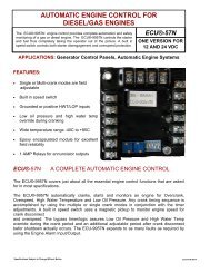
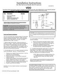
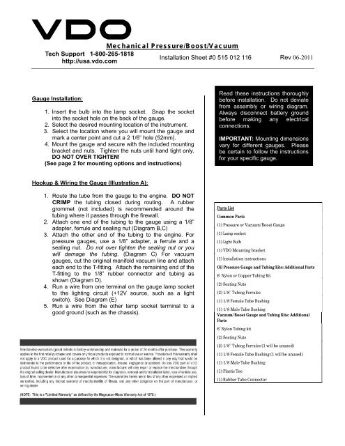
<strong>Mechanical</strong> <strong>Pressure</strong>/<strong>Boost</strong>/<strong>Vacuum</strong>Tech Support 1-800-265-1818Installation Sheet #0 515 012 116 Rev 06-2011http://usa.vdo.comGauge Installation:1. Insert the bulb into the lamp socket. Snap the socketinto the socket hole on the back of the gauge.2. Select the desired mounting location of the instrument.3. Select the location where you will mount the gauge andmark a center point and cut a 2 1/6” hole (52mm).4. Mount the gauge and secure with the included mountingbracket and nuts. Tighten the nuts until hand tight only.DO NOT OVER TIGHTEN!(See page 2 for mounting options and instructions)Read these instructions thoroughlybefore installation. Do not deviatefrom assembly or wiring diagram.Always disconnect battery groundbefore making any electricalconnections.IMPORTANT: Mounting dimensionsvary for different gauges. Pleasebe certain to follow the instructionsfor your specific gauge.Hookup & Wiring the Gauge (Illustration A):1. Route the tube from the gauge to the engine. DO NOTCRIMP the tubing closed during routing. A rubbergrommet (not included) is recommended around thetubing where it passes through the firewall.2. Attach one end of the tubing to the gauge using a 1/8”adapter, ferrule and sealing nut (Diagram B,C)3. Attach the other end of the tubing to the engine. Forpressure gauges, use a 1/8” adapter, a ferrule and asealing nut. Do not over tighten the sealing nut or youwill damage the tubing. (Diagram C) For vacuumgauges, cut the original manifold vacuum line and attacheach end to the T-fitting. Attach the remaining end of theT-fitting to the 1/8” rubber connector and tubing asshown (Diagram D).4. Run a wire from one terminal on the gauge lamp socketto the lighting circuit (+12V source, such as a lightswitch). See Diagram (E)5. Run a wire from the other lamp socket terminal to agood ground (such as the chassis).Parts ListCommon Parts(1) <strong>Pressure</strong> or <strong>Vacuum</strong>/<strong>Boost</strong> Gauge(1) Lamp socket(1) Light Bulb(1) <strong>VDO</strong> Mounting bracket(1) Installation instructionsOil <strong>Pressure</strong> Gauge and Tubing Kits: Additional Parts6' Nylon or Copper Tubing Kit(2) Seating Nuts(2) 1/8" Tubing Ferrules(1) 1/8 Female Tube Bushing(1) 1/8 Male Tube Bushing<strong>Vacuum</strong>/<strong>Boost</strong> Gauge and Tubing Kits: AdditionalParts6' Nylon Tubing kit(2) Seating Nuts(2) 1/8" Tubing Ferrules (1 will be unused)(1) 1/8 Female Tube Bushing (1 will be unused)(1) 1/8 Male Tube Bushing(1) Plastic Tee(1) Rubber Tube Connector
<strong>Mechanical</strong> <strong>Pressure</strong>/<strong>Boost</strong>/<strong>Vacuum</strong>Tech Support 1-800-265-1818Installation Sheet #0 515 012 116 Rev 06-2011http://usa.vdo.comDiagram ADiagram CDiagram BDiagram DDiagram E