CGE High Power Connectors
CGE High Power Connectors
CGE High Power Connectors
- No tags were found...

You also want an ePaper? Increase the reach of your titles
YUMPU automatically turns print PDFs into web optimized ePapers that Google loves.
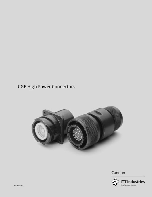
<strong>CGE</strong>ContentsIntroduction .......................................... 2Connector Design .............................. 2How to order ....................................... 3Mateability ......................................... 3Polarization ........................................... 3Technical Data ...................................... 4Panel Cut-Outs ..................................... 5Connector Dimensions .......................... 6Accessories ........................................... 9Contacts and Tools ............................... 10Product Safety Information .................. 11IntroductionThe Cannon <strong>CGE</strong> connectors are designedto transmit very high current at lowvoltage, as for example in the electricalequipment of military land- and sea-bornevehicles and in industrial applications. Theconnectors meet the mating dimensions,mechanical features and rear panelinstallation requirements of VG 95234.Ultraflexible shielded welding cables accto MTV 6145-005 are terminated to theconnectors.Connector DesignThe high power connectors <strong>CGE</strong> featureone contact in a two-piece rigid insulator.The aluminum shell has a chromate finishover cadmium. The operating temperatureranges from –55 to 125°C.The contacts made of copper or a copperalloy with hard silver finish are designedfor crimping or termination to solid copperconductors with threaded bolts. Themechanical durability is a minimum of 500mating cycles. The crimp contacts acceptwires according to DIN 46438 (25 – 240mm 2 ). Contact retention is achieved by thetwo-piece insulator which is fixed to theshell with a snap-in ring. This allowsunlimited exchange of the crimp contacts.The bayonet coupling assures fast andreliable mating and unmating. Audiblesnap-in and colour-coded snap-in pointsindicate positive mating. Plugs andreceptacles are waterproof in matedcondition up to 1 bar (35 feet of water).Connector DesignO-Ring Shell Insulator Cylindrical O-Ring Insulator Spring ringContact Contact Contactfront siderear sideSpring ring Insulator O-Ring Spring Insulator Barrel assemblyContact contact Contactrear sidefront side2Dimensions are mm (inches)Subject to changes
<strong>CGE</strong>Cable DataApprox. values for cable self-heatingWire size Max admissible Approx over-temperature due to current load: ∆ T in °Cmm 2 operating voltage 1/3 of max admissible 2/2 of max admissible max admissibleoperating voltage operating voltage operating voltage25 250 35 52 9550 300 15 25 5595 500 10 33 70150 600 5 23 60240 1000 8 30 75Cable DimensionsOuter jacketShielding braid, tinnedInner jackedCopper conductorCable designation Shell Wire size Straight plug Plug 90°size mm 2 a b max c max d +/–10,5 e1 +/–1,0 f1 +/–1,0 e2 +/–1,0 f2 +/–1,0MTV6145-005+001 16 25 7,5 +/–0,5 13,5 10,2 14,0 31,0 46,0 - -MTV6145-005+001 18 50 11,0 +/–0,5 18,0 14,3 15,0 31,0 46,0 - -MTV6145-005+001 22 95 16,0 +/–0,5 23,5 19,7 20,5 42,0 57,0 20,0 35,0MTV6145-005+001 28 150 20,5 +/–0,5 30,0 25,4 30,0 - - 25,0 40,0MTV6145-005+001 32 240 26,5 +/–0,5 36,0 32,5 30,0 54,0 69,0 25,0 40,0Panel Cut-OutsPanel cut-outs for rear and front panelmounting of receptaclesShell size Receptacles, rear panel mounting Receptacles, front panel mounting<strong>CGE</strong>0E-B-03/14<strong>CGE</strong>2E-B-16<strong>CGE</strong>2E-B-04H13 H12 H13 H12c +0,15 d +0,15 d ± 0,15 c thread d c ± 0,1516 4,5 27,7 24,6 4,5 M4 22,5 24,618 4,5 31,1 27,0 4,5 M4 27,4 27,022 4,5 37,8 31,8 4,5 M4 33,7 31,828 5,5 47,1 39,7 4,5 M4 43,5 39,732 5,5 53,8 44,5 4,5 M4 49,7 44,55
<strong>CGE</strong><strong>CGE</strong>0E...B-03Wall mounting receptacle,acc to VG 96929B1,rear panel mounting,four threaded holes in flange,adapter for heat shrink boot,metric crimp contactsShell a d 1d 2d 3e g h l 1l 4l 5l 6size – 0,15 ± 0,15 ± 0,3 ± 0,1 ± 0,1 ± 0,2 ± 0,3 ± 0,3 ± 0,15 ± 0,316 27,4 20,0 22,1 M4 24,6 3,2 12,0 41,0 20,0 3,2 32,522 37,4 45,8 49,2 M4 31,8 3,2 20,8 55,0 23,15 4,0 41,032 53,4 45,8 49,2 M5 44,5 3,5 28,0 66,8 29,0 4,0 57,0<strong>CGE</strong>1E...B-03Cable connecting plug, straigt,adapter for heat shrink boots,metric crimp contactsShell size a d 1d 2g h l 1– 0,15 ± 0,15 ± 0,15 ± 0,1 ± 0,15 ± 0,318 30,8 25,0 27,0 3,2 20,0 50,022 37,4 31,5 34,9 3,2 20,5 54,028 53,4 45,8 50,0 3,5 28,0 66,832 46,7 41,0 44,4 3,5 25,0 65,8<strong>CGE</strong>1E...B-14Cable connecting plug,shielded version,metric crimp contactsShell size a b c d g h l 1SW1 SW2± 0,15 ± 0,3 ± 0,2 max max18 37,4 42,0 37,0 25,5 22,5 48,5 95,5 34 386Dimensions are mm (inches)Subject to changes
<strong>CGE</strong><strong>CGE</strong>2E...B-04<strong>CGE</strong>2E...B-04-05Box mounting receptacle,rear panel mounting,-04 – four threaded holes in flange,-04-05 – four through holes in flangeShell size a d 1d e h l 1l 2n– 0,15 ± 0,15 Mod 04 Mod 05 ± 0,1 ± 0,2 ± 0,3 ± 0,3 ± 0,116 27,4 22,1 M4 4,3 24,6 20,0 41,0 32,5 3,218 30,8 27,0 M4 4,3 27,0 23,15 50,0 35,0 4,022 37,4 34,9 M4 4,3 31,8 23,15 54,0 41,0 4,028 46,6 42,7 M4 4,3 39,7 - 65,3 50,8 4,032 53,4 49,2 M5 5,3 44,5 29,0 66,8 57,0 4,0<strong>CGE</strong>2E...B-16Box mounting receptacle,front panel mounting,four through holes in flange,threaded bolt termination forsolid copper railShell a d 1d 2d e g h l 1l 2l 5l 7n SWsize – 0,15 – 0,15 + 0,2 ± 0,1 ± 0,3 max ± 0,3 ± 0,5 + 0,3 ± 0,1518 30,8 M8 26,9 4,3 27,0 4,0 27,5 55,0 23,15 15,0 35,0 4,0 322 37,4 M12 33,2 4,3 31,8 4,4 38,0 65,5 23,15 25,3 41,0 4,0 628 46,6 M12 42,8 4,3 39,7 4,0 32,0 61,0 24,15 20,0 50,8 4,0 632 53,4 M16 49,2 4,3 44,5 6,0 44,5 73,0 29,0 22,0 57,0 4,0 8<strong>CGE</strong>6E...B-03Straight plugacc to VG 96929A2,adapter for heat shrink boots,metric crimp contactsShell size d 1d 2d 3g h l 1max – 0,1 max ± 0,2 max16 32,0 20,2 22,3 4,3 27,0 44,018 36,5 25,8 28,0 4,3 31,8 53,022 43,1 31,5 35,0 4,3 39,7 57,032 60,1 45,4 49,2 4,3 44,5 65,07
<strong>CGE</strong><strong>CGE</strong>6E...B-14Straight plugacc to VG 96929F,360° HF shielding by grounding fingers,endbells for clamp connection of shieldingbraid and for heat shrink boots,metric crimp contactsShell size c d 1d 2d 4g h l 1SW± 0,3 max ± 0,15 ± 0,1 ± 0,1 ± 0,4 max16 26,0 32,0 24,0 15,5 1,0 25,5 68,0 2618 32,0 36,5 28,7 20,0 1,0 26,0 73,5 3222 37,0 43,1 33,7 25,5 1,0 26,0 84,0 3828 44,0 53,0 40,0 32,0 1,0 26,0 98,0 5032 31,0 60,1 47,2 38,0 1,0 28,0 95,5 54<strong>CGE</strong>8E...B-0390° plugwith adapter for heat shrink boots,metric crimp contacts<strong>CGE</strong>8E...B-1490° plugacc to VG 96929E,with grounding fingers, adapter forshielding braid and for use with heatshrink boots, metric crimp contactsShell size d 1d 3l 1l 3l 4l 6l SWmax max ± 1,0 max max ± 0,2 max22 43,1 42,0 80,0 41 56 3,2 101,0 3828 53,0 48,0 78,0 41 56 3,2 102,0 5032 60,1 52,5 84,0 41 56 3,2 112,0 52<strong>CGE</strong>9E...X-B-04Bulkheadacc to VG 96929C2,with through holes in flangeShell size a d 1e l 1l 2l 3l 4– 0,15 ± 0,1 max ± 0,3 ± 0,1 ± 0,322 46,7 5,3 39,7 51,5 20,6 4,0 50,88Dimensions are mm (inches)Subject to changes
<strong>CGE</strong>AccessoriesDust cap 121004for plugsOrder reference Size a b c d+ 0,5 ± 10,0 max maxCA121004-4 16S 4,3 113 29,0 29,9CA121004-6 18 4,3 127 30,0 33,3CA121004-8 22 4,3 140 30,0 39,9CA121004-10 28 4,3 197 30,0 49,2CA121004-11 32 5,5 197 30,0 55,9Dust cap 121003for receptaclesOrder reference Size a b c d+ 0,5 ± 10,0 max maxCA121003-4 16S 4,3 100 19,5 32,6CA12100436 18 4,3 113 25,4 36,7CA121003-8 22 4,3 127 25,4 43,3CA121003-10 28 5,5 169 25,4 52,6CA121004311 32 5,5 169 25,4 59,3Dummy receptacleOrder ref. Size a b d d 1e f g h± 0,3 ± 0,15 + 0,2 ± 0,2 +0,3 / – 0,1 + 0,1 + 0,15248-8504-000 16S 32,5 24,6 3,2 M4 21,5 18,3 29,6 27,4248-8506-000 18 35,0 27,0 3,2 M4 27,2 23,15 23,8 30,8248-8508-000 22 41,0 31,8 3,2 M4 27,2 23,15 30,0 37,4248-8510-000 28 50,8 39,7 3,7 M5 28,2 24,15 38,8 46,7248-8511-000 32 57,0 44,5 4,4 M5 28,2 24,15 45,2 53,49
<strong>CGE</strong>AccessoriesSealing gasketsfor rear panel mounting onlyShell Order references Order referencessize Polychloroprene Alu-Flex(shielded version)16 075-8504-000 075-8504-00118 075-8505-000 075-8505-00122 075-8507-000 075-8507-00128 075-8509-000 075-8509-00132 075-8510-000 075-8510-001O Ringsfor sealing of front mounting receptaclesare included in shipmentContactsOrder references for single contactsShell size Spring contact Cylindrical contact Contact type Crimp sleeveH24 031-8564-000 330-8697-000 Crimp with031-8567-000 330-8696-000 threaded bolt031-8658-000 031-8701-002 for 90° plug 252-8583-000H15 031-8663-000 330-8719-000 with threaded bolt031-8669-000 031-8701-000 for 90° plug 252-8583-000031-8701-004 430-8561-009 Crimp versionH9 031-8649-000 330-8698-000 Crimp with031-8660-000 330-8695-000 threaded bolt031-8659-000 031-8701-000 for 90° plug 252-8583-000H5 031-8655-000 330-8710-000 crimp with031-8656-000 330-8712-000 threaded boltH2 031-8616-000 330-8623-000 crimp versionH9 – 031-8705-000 for bulkheadNote: When choosing the contacts please make sure that the voltage carrying side of the connectionis quipped with the cylindrical contact.Crimp ToolsDescription Designation Order reference1 Hand pump 4601.00000.330 121586-00272 Foot operation for hand pump 4601.51000.330 121586-00083 <strong>High</strong> pressure hose, length 2 m 4604.00000.020 121586-00234 Crimp head 4632.00000.601 121586-00315 Safety device incl. bench mounting CT121086-3079 121086-30796 Positioner (to be used with121086-3079 only) CT121086-3080 121086-3080Right hand photograph:Electro-hydraulic crimp tool HK12EL.Available upon request – please consultfactoryCrimp diesContact Order referencesize upper crimp dies lower crimp diesH2 317-8578-006 317-8578-007H5 317-8578-008 317-8578-009H9 317-8578-004 317-8578-005H15 317-8578-002 317-8578-003H24 317-8578-000 317-8578-001Special Allen Wrenchesfor endbell assemblyShell sizeOrder reference16 <strong>CGE</strong>-SW2618 <strong>CGE</strong>-SW2622 <strong>CGE</strong>-SW2628 <strong>CGE</strong>-SW2610Dimensions are mm (inches)Subject to changes
<strong>CGE</strong>Product safety InformationTHIS NOTE SHOULD BE READ IN CONJUNCTIONWITH THE PRODUCT DATA SHEET/CATALOGUE.FAILURE TO OBSERVE THE ADVICE IN THIS INFOR-MATION SHEET AND THE OPERATING CONDITIONSSPECIFIED IN THE PRODUCT DATA SHEET/CATALOGUE COULD RESULT IN HAZARDOUSSITUATIONS.1. MATERIAL CONTENT AND PHYSICALFORMElectrical connectors do not usually containhazardous materials. They contain conducting andnon-conducting materials and can be divided intotwo groups.a) Printed circuit types and low cost audio typeswhich employ all plastic insulators and casings.b) Rugged, Fire Barrier and <strong>High</strong> Reliability typeswith metal casings and either natural rubber,synthetic rubber, plastic or glass insulatingmaterials.Contact materials vary with type of connector andalso application and are usually manufactured fromeither copper, copper alloys, nickel, alumel, chromelor steel. In special applications, other alloys maybe specified.2. FIRE CHARACTERISTICS AND ELECTRICSHOCK HAZARDThere is no fire hazard when the connector iscorrectly wired and used within the specifiedparameters. Incorrect wiring or assembly of theconnector or careless use of metal tools orconductive fluids, or transit damage to any of thecomponent parts may cause electric shock orburns. Live circuits must not be broken by separatingmated connectors as this may cause arcing,ionisation and burning.Heat dissipation is greater at maximum resistancein a circuit. Hot spots may occur when resistanceis raised locally by damage, e.g. cracked ordeformed contacts, broken strands of wire. Localoverheating may also result from the use of theincorrect application tools or from poor qualitysoldering or slack screw terminals. Overheating mayoccur if the ratings in the Product Data Sheet/Catalogue are exceeded and can cause breakdownof insulation and hence electric shock.If heating is allowed to continue it intensifies byfurther increasing the local resistance through lossof temper of spring contacts, formation of oxidefilm on contacts and wires, and leakage currentsthrough carbonisation of insulation and trackingpaths. Fire can then result in the presence ofcombustible materials and this may release noxiousfumes. Overheating may not be visually apparent.Burns may result from touching overheatedcomponents.3. HANDLINGCare must be taken to avoid damage to anycomponent parts of electrical connectors duringinstallation and use. Although there are normallyno sharp edges, care must be taken when handlingcertain components to avoid injury to fingers.Electrical connectors may be damaged in transit tothe customers, and damage may result in creationof hazards. Products should therefore be examinedprior to installation/use and rejected if found to bedamaged.4. DISPOSALIncineration of certain materials may releasenoxious or even toxic fumes.5. APPLICATION<strong>Connectors</strong> with exposed contacts should not beselected for use on the current supply side of anelectrical circuit, because an electric shock couldresult from touching exposed contacts on anunmated connector. Voltages in excess of 30 V acor 42.5 V dc are potentially hazardous and careshould be taken to ensure that such voltages cannot be transmitted in any way to exposed metal partsof the connector body. The connector and wiringshould be checked, before making live, to have nodamage to metal parts or insulators, no solder blobs,loose strands, conducting lubricants, swarf, or anyother undesired conducting particles. Insulationresistance should be checked to make certain thatno low resistance joints or spurious conducting pathare existing between contacts and exposed metalparts of the connector body. Further the contactresistance of the connectors should be measuredwithin the electrical circuit in order to identify highresistances which result in excessive connectorheating.ITT Cannon manufactures the highest quality products available in the marketplace; however these products are intendedto be used in accordance with the specifications in this catalog. Any use or application that deviates from stated operatingspecifications is not recommended and may be unsafe. No information and data contained in this catalog shall be construedto create any liability on the part of Cannon. Any new issue of this catalog shall automatically invalidate and supersedeany and all previous issues. A limited warranty applies to Cannon products. Except for obligations assumed by Cannonunder this warranty, Cannon shall not be liable for any loss, damage, cost of repairs, incidental or consequentialdamages of any kind, whether or not based on express or implied warranty, contract, negligence or strict liabilityarising in connection with the design, manufacture, sale, use or repair of the products. Product availability, prices anddelivery dates are exclusively subject to our respective order confirmation form; the same applies to orders based ondevelopment samples delivered. This catalog is not be construed as an offer. It is intended merely as an invitation to makean offer. By this publication, Cannon does not assume responsibility or any liability for any patent infringements or otherrights of third parties which may result from its use. Reprinting this catalog is generally permitted, indicating the source.However, Cannon's prior consent must be obtained in all cases.Cannon is a trademark of ITT Industries, IncAlways use the correct application tools as specifiedin the Data Sheet/Catalogue.Do not permit untrained personnel to wire, assembleor tramper with connectors.For operation voltage please see appropriate nationalregulations.IMPORTANT GENERAL INFORMATION.1. Air and creepage paths/Operating voltageThe admissible operating voltages depend on theindividual applications and the valid national andother applicable safety regulations.For this reason the air and creepage path dataare only reference values. Observe reduction of airand creepage paths due to PC board and/or harnessing.2. TemperatureAll information given are temperature limits. Theoperation temperature depends on the individualapplication.3. Other important informationCannon continuously endeavours to improve theirproducts. Therefore, Cannon products may deviatefrom the description, technical data and shape asshown in this catalogue and data sheets.4. Harnessing and Assembly InstructionsIf applicable, our special harnessing and/or assemblyinstruction has to be adhered to. This is providedat request.11