EM-241A DC-MOTOR CONTROLLER 12-24V 15A - Electromen
EM-241A DC-MOTOR CONTROLLER 12-24V 15A - Electromen
EM-241A DC-MOTOR CONTROLLER 12-24V 15A - Electromen
- No tags were found...

Create successful ePaper yourself
Turn your PDF publications into a flip-book with our unique Google optimized e-Paper software.
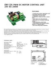
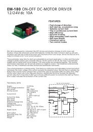
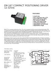
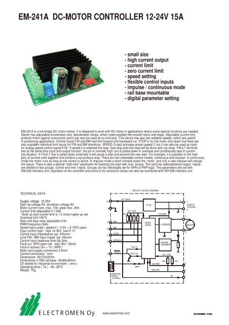
<strong>EM</strong>-<strong>241A</strong> <strong>DC</strong>-<strong>MOTOR</strong> <strong>CONTROLLER</strong> <strong>12</strong>-<strong>24V</strong> <strong>15A</strong>- small size- high current output- current limit- zero current limit- speed setting- flexible control inputs- impulse / continuous mode- rail base mountable- digital parameter setting<strong>EM</strong>-<strong>241A</strong> is a full bridge <strong>DC</strong>-motor starter. It is designed to work with <strong>DC</strong>-motor in applications where some special functions are needed.Starter has adjustable acceleration and deceleration ramps, which make possible the smooth starts and stops. Adjustable current limitprotects motor against overcurrent and it can also be used as an end-stop. This device has also two settable speeds, which are usefullin positioning applications. Control inputs FW and BW start the forward and backward run. STOP is for the motor shut-down but there arealso available individual limit inputs for FW and BW directions. SPEED-2 input activates preset speed-2, but it can also be used as inputfor analog speed control signal 0-5V. If speed-2 is selected the stop, fault stop and limit stop will be done with out ramp. FAULT terminalhas at the same time input and output function, the pin is normally high, but is pulled down in overheat and conditionally also in currenttrip situation. If FAULT-line is pulled down externally it will cause a stop and prevent the new start. For example, it is possible to link faultpins of several units together and achieve a syncronous stop. There are two selectable control modes, continuous and impulse. In continuousmode the motor runs as long as the control is active. In impulse mode a short comand starts the motor, and only a new impulse will changethe status. There is also a special "start-kick" parameter for boosting the start with max. torque. The card has selectableinput logics. Inputsare divided in two groups, control and limit -inputs. Groups can be individually set for NPN or PNP logic. The parameters are set with<strong>EM</strong>-236 interface unit. Operation of the controller and some of its functional values can also be monitored with <strong>EM</strong>-236 interface unit.TECHNICAL DATA<strong>EM</strong>-<strong>241A</strong> BLOCK DIAGRAMSupply voltage 10-35VStart up voltage 9V, shutdown voltage 8VMotor current cont. max. <strong>15A</strong>, peak max. 30ACurrent limit adjustable 0.1-20ANote! at start current limit is 1.5 times higher as setOverheat limit 100°CStart and stop ramp adjustable 0-5sPWM frequency 2kHzSpeed input scale ( speed-2 ) 0-5V = 0-100% pwmInput control logic: high =4-30V, low=0-1VControl input impedances typ. 47kohmLimit FW / BW input imped. typ 10kohmControl input response time typ 5ms.Fault out. NPN open coll. max 30V / 50mAFault in actives Uin < 1V ( NPN )Motor and supply connectors 2.5mmControl connectors 1mmDimensions 42x72x25mmDimensions in DIN-rail base 45x80x45mmCE-tested for industrial environment ( emc )Operating temp ( Ta ) -40...60°CWeight 75g14891011<strong>12</strong>13FWBWSTOPSPEED-2FAULTparametersettingconnector5V/ 10mA47knpn / pnpfault infault outdataU-regDRIVELOGIClimit BWlimit FWU-OVERH-BRIDG<strong>EM</strong>OTORCURRENTnpn / pnp10k5V10k-+7SUPPLY<strong>12</strong>/<strong>24V</strong>dc45<strong>MOTOR</strong>6321ELECTROMEN Oywww.electromen.com
CONNECTIONSSupply voltage must be filtered <strong>DC</strong> of 10-35V,and ripple should be less than 30% at full load.CAUTION ! Wrong polarity can damage the unit.CAUTION ! Unit doesn't have an internal fuse, soan external fuse should be added if fuse required.MONITORABLE VALUES1/5 Motor current 0-20A ( 0-200)2/5 PWM-level-% 0-100% (0-100)3/5 hour counter (max.65535h)4/5 start counter (max.65535)5/5 carry counter for start counterFAULT-LED signal codes1. power on one blink2. current on limit led is lit3. current trip fast blinking...4. zero-cur trip long blink- short pause...5. overvoltage 4 x blink -pause...6. overheat short blink- long pause...7. timeout 3 x blink + long blink...8. fault input 2 x short + 1x long blink...ADJUSTMENT AND SETTINGSAdjusting and parameter setting of eg.current limit value, ramp times and speed-2value is done with the <strong>EM</strong>-236 interface unit.With <strong>EM</strong>-236 the parameters and adjustedvalues can also be copied to multibledevices accurately and reliably.SETTABLE PARAMETERS prog v1.3( defaults values in brackets )1 command mode: continuous = 0, impulse= 1 ( 0 )2 start condition combinations: 0-3 ( 1 )0= start both direction after I-trip and Stop1= start only opposite direction after I-trip2= start only opposite direction after Stop3= start only opposite direction after I- and Stop3 input logic combinations 0-3 PNP/NPN ( 0 )0= command and limit inputs as PNP ( positive )1= command inputs NPN, and limit inputs PNP2= command inputs PNP. and limit input NPN3= command and limit inputs NPN ( negative )4 running speed-1: 0-100% / 0-100 ( 100 )5 running speed-2: 0-100% / 0-100 ( 50 )Note: If selected to 0 "speed2-input" isused as analog 0-5V speed control input.6 current limit FW: 0.1-20A / 1-200 ( 30 )7 current limit REV: 0.1-20A / 1-200 ( 30 )8 Trip combinations: 0-3 ( 1 )0= no I-trip, no zero-current-trip1= only I-trip2= only zero-current-trip3= both I-trip and zero-current-trip9 I-trip delay: 0-255ms / 0-255 ( 20 )10 Fault output combinations: 0-3 ( 1 )0= I-trip and zero current won´t cause fault output signal1= only I-trip causes fault output signal2= only zero current causes fault output signal3= both I-trip and zero currenT causes fault output signal.11 overvoltage limit: 15-40V / 15-40 ( 35 )Overvoltage can be caused by load driving the motor orwhen braking the speed down but supply can not acceptthe current back from driver. Exceeding the limit will causethe power stage set to free-wheel state.With a direct battery supply the brake current is charging thebattery and the voltage will not normally rice.<strong>12</strong> load compensation: 0-255 / 0-255 ( 0 )Load compensation ( RxI ) improves low speed and starttorgue, but too high compensation achieve unstable running.Run motor at low speed ( 30% ) Increace compensationwith small steps until motor start behaviour unstable,then decrease value about 10%13 timeout: 0-255s. / 0-255 (0=not in use) ( 0 )14 Reset for start and hour-counter 0/1 ( 0 )selecting 1 and push save = reset counters15 start ramp: 0-5s / 0-500 ( 100 )16 stop ramp: 0-5s / 0-500 ( 100 )17 start kick 0-200ms / 0-200 ( 0 )gives short 0-200 full drive pulse for startELECTROMEN Oywww.electromen.com