Technical data sheet Damper actuator TM24A-SR 040 .. 01 ... - Belimo
Technical data sheet Damper actuator TM24A-SR 040 .. 01 ... - Belimo
Technical data sheet Damper actuator TM24A-SR 040 .. 01 ... - Belimo
- No tags were found...

You also want an ePaper? Increase the reach of your titles
YUMPU automatically turns print PDFs into web optimized ePapers that Google loves.
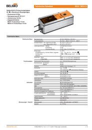
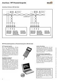
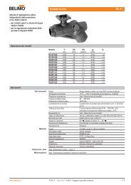
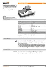
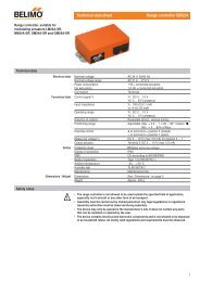
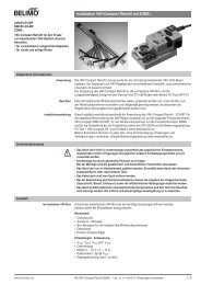
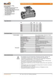
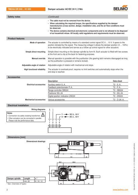
<strong>TM24A</strong>-<strong>SR</strong> <strong>040</strong> .. <strong>01</strong> 005<strong>Damper</strong> <strong>actuator</strong> AC/DC 24 V, 2 NmSafety notes(Continued)• The cable must not be removed from the device.• When calculating the required torque, the specifications supplied by the dampermanufacturers (cross section, design, installation site), and the air flow conditions mustbe observed.• The device contains electrical and electronic components and is not allowed to be disposedof as household refuse. All locally valid regulations and requirements must be observed.Product featuresMode of operationSimple direct mountingManual overrideThe <strong>actuator</strong> is controlled by means of a standard control signal DC 0 ... 10 V. It opens to theposition dictated by this signal. The measuring voltage U allows the damper position (0 ... 100%)to be electrically indicated and serves as a follow-up control signal for other <strong>actuator</strong>s.Simple direct mounting on the damper spindle by form-fit. Each <strong>actuator</strong> is fitted with two screwsat the front and a clip at the back for fastening purposes.Manual operation is possible with the pushbutton (the gearing latch remains disengaged as longas the pushbutton is pressed or remains locked).Adjustable angle of rotationHigh functional reliabilityAdjustable angle of rotation with mechanical end stops.The <strong>actuator</strong> is overload-proof, requires no limit switches and automatically stops when theend stop is reached.AccessoriesDescriptionData <strong>sheet</strong>Electrical accessories Auxiliary switch S..A.. T2 - S..A..Feedback potentiometer P..A..T2 - P..A..Range controller SBG24T2 - SBG24Positioner SG..24T2 - SG..24Digital position indication ZAD24T2 - ZAD24Mechanical accessories Various accessories T2 - Z-LM..A..Electrical installationWiring diagramsNotes• Connection via safety isolating transformer. !• Other <strong>actuator</strong>s can be connected in parallel.Please note the performance <strong>data</strong>.T~– +1 2 3 5YUDC 0…10 VDC 2…10 VDimensions [mm]Dimensional drawings<strong>Damper</strong> spindle Length x *min. 20 8 / 10 / 12* See «Overview of Types»4766305.216 1162028.5 100.52 www.belimo.comx22 94 4161Data <strong>sheet</strong> T2-<strong>TM24A</strong>-<strong>SR</strong> <strong>040</strong>..<strong>01</strong>005 • en • v1.0 • 08.2005 • Subject to modifications