CR24, single room controller - Belimo
CR24, single room controller - Belimo
CR24, single room controller - Belimo

Create successful ePaper yourself
Turn your PDF publications into a flip-book with our unique Google optimized e-Paper software.
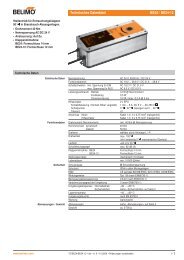
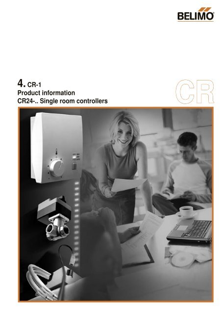
BC4. CR-1Product information<strong>CR24</strong>-.. Single <strong>room</strong> <strong>controller</strong>sCR
Overview of the systemBCSingle <strong>room</strong> <strong>controller</strong>s<strong>CR24</strong>-B1 <strong>CR24</strong>-B2 <strong>CR24</strong>-B3VAV applicationsCompactUniversalWater applicationsRotary actuator andcontroll ball valvesAir applicationsDamper actuatorsTable of contentsOverview of the system 2Overview of functions 3Data sheets<strong>CR24</strong>-B1 / <strong>CR24</strong>-A1 Single <strong>room</strong> <strong>controller</strong>s4<strong>CR24</strong>-B2 / <strong>CR24</strong>-A2 Single <strong>room</strong> <strong>controller</strong>s6<strong>CR24</strong>-B3 / <strong>CR24</strong>-A3 Single <strong>room</strong> <strong>controller</strong>s8Operation (<strong>CR24</strong>-B.. only) 10FunctionsIntroductionSetpoint calculationEnergy hold offStand-byVAV-FunctionExternal temperature sensorExternal setpoint shiftAir flushChange-overBoostChilled ceilingInstallation / Dimensions 17Commissioning / Service 18Notes 191111121212131313141516ENG-93001-93427-08.04-2M • Printed in Switzerland • ZSD • Subject to technical modifications2
BCOverview of functionsENG-93001-93427-08.04-2M • Printed in Switzerland • ZSD • Subject to technical modificationsOverview of <strong>CR24</strong>-B.. functions<strong>CR24</strong>-B1 <strong>CR24</strong>-B2 <strong>CR24</strong>-B3Power supply AC 24 V / 50/60 Hz • • •Application / temperature range– Room temperature control in comfort zone • • •– Internal temperature sensor(Type NTC, sensing range 10...45°C) • • •– Setpoint (adjustment range 15...36°C) • • •Operation (<strong>CR24</strong>-B.. only) • • •– Mode selection Switch: AUTO – ECO – MAX • • •– Mode indication LEDs: AUTO – ECO – MAX • • •– Setpoint adjustm. Rotary knob: ±3 K • • •Inputs Number 4 5 5– Energy hold off • • •– Stand-by • 1) • •– Change-over • 1) • 2)– Chilled ceiling with dew point limiting and change-over • 2)– Air flush •– Boost • 2)– External temperature sensorType NTC, sensing range 10...45°C • • •– External setpoint shift 0...10 V • • •Outputs Number 1 2 3– (0)2...10 V system output for <strong>Belimo</strong> VAV <strong>controller</strong>or change-over • 3)– (0)2...10 V system output for <strong>Belimo</strong> VAV <strong>controller</strong> • •– Heating output 1 • •– Heating or cooling output, change-over 0...10 V • 4)Functions– Control characteristics P P P / PI– P-band switchable • • •– Boost function max or temperature-controlled, selectable •– Volume increase in heating mode, selectable • •– Internal function test, including nominal voltage test • • •– Commissioning mode with output and sequence simulation • • •– VAV <strong>controller</strong> diagnosis via integrated PC-Tool connection • • •MountingSurface mountingwith flush-mounted or surface-mounted connectionHousing colorsBaseplate NCS2005-R80B light gray(corresponds approx. to RAL 7035)Cover RAL 9003 signal white• • •• • •1) The stand-by input is not available in change-over (C/O) mode or in heating <strong>controller</strong> applications, as it isassigned to the change-over input function. <strong>CR24</strong>-B3 should be used if the stand-by function is needed ina change-over application.2) The boost function is not available in change-over mode or in chilled ceiling applications with dew pointlimiting. A combination of change-over and dew point limiting is possible.3) The output can either be used as a common cooling and heating output in change-over mode or exclusivelyas a cooling or heating output. The stand-by function is not available in change-over mode or inheating <strong>controller</strong> applications.4) The output can either be used as a common cooling and heating output in change-over mode or exclusivelyas a cooling or heating output.Additional documentationComprehensive and regularly updated documentation with descriptions of specific applications isavailable for all <strong>controller</strong>s.Brief descriptionThe new developed <strong>CR24</strong>-.. <strong>controller</strong> generationprovides the foundation for modern <strong>single</strong><strong>room</strong> concepts.The technology, functionality and handlingof the new microprocessor-controlled <strong>room</strong>temperature <strong>controller</strong>s are perfectly adaptedto the BELIMO actuators for motorized air andwater final controlling elements.The functional classification into three basictypes with up to three output sequences andthe large number of specific applicationsfacilitate cost-effective system solutions forindividually controlling the <strong>room</strong> climate andreducing energy consumption. The <strong>controller</strong>scan be used in both pure VAV and combinedsystems with 2 and 4-pipe water applications(radiators, air heaters/coolers, heated/chilledceilings).Device variants– Standard <strong>CR24</strong>-B.. type with operator panel(setpoint adjustment, mode switch andstatus indication). For operation, refer topage10.– Type <strong>CR24</strong>-A..: same functionality as the<strong>CR24</strong>-B.. but without an operator panel.NotesUnless otherwise expressly mentioned, allreferences contained in this document to the<strong>CR24</strong>-B.. also apply to the <strong>CR24</strong>-A...AccessoriesTypeCRZA-ACRZA-BCRZWDescriptionSpare cover for A-typesSpare cover for B-types(with operator panel)Spare baseplateFitting to all types3
<strong>CR24</strong>-B1 Single <strong>room</strong> <strong>controller</strong>sBCTemperature <strong>controller</strong>s for <strong>single</strong> <strong>room</strong> applications with one analog output.• The analog output ao1 can be used in VAV applications to contol one or moreVAV <strong>controller</strong>s.• In change-over applications, the analog output ao1 can be changed over from coolingto heating mode via an input.Technical dataNominal voltageAC 24 V 50/60 HzFor wire sizing3 VA, without actuatorsPower supply rangeAC 19.2...28.8 VControl characteristicsP– P-band heating / cooling Selectable: 1.5 / 1.0 K or 3.0 / 2.0 KExternal temperature sensor (ai1) Type NTC, 5 kΩ, sensing range 10...45°CHeating setpointRange 15...36°C (default 21°C)– Energy hold off Heating 15°C / cooling 40°C– Stand-by Heating –2 K / cooling +3 KDead band1 KFrost limit temperature 10°COperation (<strong>CR24</strong>-B.. only)– Mode switch and status indication (LEDs) AUTO (green) – ECO (orange) – MAX (red)– Rotary knob for setpoint adjustment ±3 KInputs2 x analog, 2 x digital– External temperature sensor (ai1) Type NTC, 5 kΩ, sensing range 10...45°C– External setpoint shift (ai2) 0...10 V corresponds to 0...10 K– Digital inputs (di1, di2) Contact rating 10 mAOutput1 x analog– VAV system output (ao1) (0)2 ... 10 V, max. 5 mACommunication port for field devices 2 x PP (for PC-Tool, MFT remote control etc.)HousingBaseplate: NCS2005-R80B light gray (correspondsapprox. to RAL 7035) / Cover: RAL 9003 signal whiteConnectionsTerminal block 1...3: 2.5 mm2Terminal block 4...8: 1.5 mm2Ambient conditions– Operation 0...+50°C / 20...90% rH (without condensation)– Transport and storage –25...+70°C / 20...90% rH (without condensation)Standards– Protection class III Safety extra-low voltage– Degree of protection IP 30 to EN 60529– Mode of operation Type 1 to EN 60730-1– Software class A to EN 60730-1– EMC CE conformity to 89/336/EECDimensions (H x W x D)99 x 84 x 32 mmWeight105 g4Functions• Energy hold offIn energy saving mode, the <strong>room</strong> temperatureis reduced to building protection level,i.e. either the heating setpoint is significantlyreduced or the cooling setpoint is significantlyincreased, for instance in a <strong>room</strong> with anopen window.• Stand-byThe <strong>room</strong> temperature is reduced to standbylevel, i.e. either the heating setpoint isslightly reduced or the cooling setpoint isslightly increased, for instance in a <strong>room</strong>that is temporarily unoccupied.• FrostThe frost protection function is activated if theactual <strong>room</strong> temperature falls below 10°C.• Change-overChange-over heating or heating/cooling.• External temperature sensorAn external temperature sensor can beconnected to the analog input ai1, for instancein order to measure the average<strong>room</strong> temperature in the exhaust air duct.• External setpoint shiftAn external DC 0...10 V signal at theanalog input ai2 can be used to shift thebasic setpoint 0...10 K, for instance for thesummer/winter compensation.These functions are described in detail onpages 11 to 17.Device variantType <strong>CR24</strong>-A1, same functionality as the<strong>CR24</strong>-B1 but without an operator panel.ENG-93001-93427-08.04-2M • Printed in Switzerland • ZSD • Subject to technical modifications
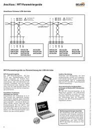
BC<strong>CR24</strong>-B1 Single <strong>room</strong> <strong>controller</strong>sWiring diagramConfigurationAC 24 V+~NTC0...10 VDIPDefaultsettings1 21 P-band normal P-band wide2 Input di2Stand-byInput di2Change-overao1 U5 1 U5 21 2 6 7 83 4 5ai/di1 di2 ai2<strong>CR24</strong>-B1InputsOutputs3ai1 External temperature sensor 6 ao1 System output for <strong>Belimo</strong> VAV <strong>controller</strong>di1 Energy hold off Other connections4 di2 Stand by 7 PP1 Diagnostics socket 15 ai2 External setpoint shift 8 PP2 Diagnostics socket 2Principal diagram10Y [V].V max10Y [V]Change over.V max20W C.V mint R [°C]20W HW C.V mint R [°C]ENG-93001-93427-08.04-2M • Printed in Switzerland • ZSD • Subject to technical modificationsKeyY [V] Output voltage in volt max Maximum volume flowt R [°C] Room temperature in degrees centigrade min Minimum volume flowW H Heating setpointW C Cooling setpoint5
<strong>CR24</strong>-B2 Single <strong>room</strong> <strong>controller</strong>sBCTemperature <strong>controller</strong>s for <strong>single</strong> <strong>room</strong> applications with two analog outputs.• The analog output ao1 can be used in VAV applications to contol one or moreVAV <strong>controller</strong>s.• The analog heating output ao3 supplies a 3-point signal.Technical dataNominal voltageAC 24 V 50/60 HzFor wire sizing3 VA, without actuatorsPower supply rangeAC 19.2...28.8 VControl characteristicsP– P-band heating / cooling Selectable: 1.5 / 1.0 K or 3.0 / 2.0 KExternal temperature sensor (ai1) Type NTC, 5 kΩ, sensing range 10...45°CHeating setpointRange 15...36°C (default 21°C)– Energy hold off Heating 15°C / cooling 40°C– Stand-by Heating –2 K / cooling +3 KDead band1 KFrost limit temperature 10°COperation (<strong>CR24</strong>-B.. only)– Mode switch and status indication (LEDs) AUTO (green) – ECO (orange) – MAX (red)– Rotary knob for setpoint adjustment ±3 KInputs2 x analog, 3 x digital– External temperature sensor (ai1) Type NTC, 5 kΩ, sensing range 10...45°C– External setpoint shift (ai2) 0...10 V corresponds to 0...10 K– Digital inputs (di1, di2, di3) Contact rating 10 mAOutputs2 x analog– VAV system output (ao1) (0)2 ... 10 V, max. 5 mA– Heating output (ao3) 3-point, AC 24 V, max. source current 0.5 A / 10 VA(optimized for actuators with a running time ofapprox. 150 s)Communication port for field devices 2 x PP (for PC-Tool, MFT remote control etc.)HousingBaseplate: NCS2005-R80B light gray (correspondsapprox. to RAL 7035) / Cover: RAL 9003 signal whiteConnectionsTerminal block 1... 3: 2.5 mm2Terminal block 4...12: 1.5 mm2Ambient conditions– Operation 0...+50°C / 20...90% rH (without condensation)– Transport and storage –25...+70°C / 20...90% rH (without condensation)Standards– Protection class III Safety extra-low voltage– Degree of protection IP 30 to EN 60529– Mode of operation Type 1 to EN 60730-1– Software class A to EN 60730-1– EMC CE conformity to 89/336/EECDimensions (H x W x D)99 x 84 x 32 mmWeight105 g6Functions• Energy hold offIn energy saving mode, the <strong>room</strong> temperatureis reduced to building protection level,i.e. either the heating setpoint is significantlyreduced or the cooling setpoint is significantlyincreased, for instance in a <strong>room</strong> with anopen window.• Stand-byThe <strong>room</strong> temperature is reduced to standbylevel, i.e. either the heating setpoint isslightly reduced or the cooling setpoint isslightly increased, for instance in a <strong>room</strong>that is temporarily unoccupied.• FrostThe frost protection function is activated if theactual <strong>room</strong> temperature falls below 10°C.• Air flushThe <strong>room</strong> can be ventilated with themaximum volume flow (max), for instancein order to purge conference <strong>room</strong>s, hotel<strong>room</strong>s etc.• External temperature sensorAn external temperature sensor can beconnected to the analog input ai1, for instancein order to measure the average<strong>room</strong> temperature in the exhaust air duct.• External setpoint shiftAn external DC 0...10 V signal at theanalog input ai2 can be used to shift thebasic setpoint 0...10 K, for instance for thesummer/winter compensation.These functions are described in detail onpages 11 to 17.Device variantType <strong>CR24</strong>-A2, same functionality as the<strong>CR24</strong>-B2 but without an operator panel.ENG-93001-93427-08.04-2M • Printed in Switzerland • ZSD • Subject to technical modifications
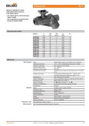
BC<strong>CR24</strong>-B2 Single <strong>room</strong> <strong>controller</strong>sWiring diagramConfigurationAC 24 V+~NTC0...10 VDIPDefaultsettings1 21 P-band normal P-band wide2 max heating off max heating 80%ao3 ao1 U5 1 U5 21 2 9 10 6 7 83 4 12 5ai/di1 di2 di3 ai2<strong>CR24</strong>-B2InputsOutputs3ai1 External temperature sensor 6 ao1 System output for <strong>Belimo</strong> VAV <strong>controller</strong>di1 Energy hold off 9/10 ao3 Heating (3-point)4 di2 Stand by Other connections5 ai2 External setpoint shift 7 PP1 Diagnostics socket 112 di3 Air flush 8 PP2 Diagnostics socket 2Principal diagram108.4Y [V].V max Hao3Air flush.Vao1max2.V min0W HW Ct R [°C]ENG-93001-93427-08.04-2M • Printed in Switzerland • ZSD • Subject to technical modificationsKeyY [V] Output voltage in volt ao.. Analog outputst R [°C] Room temperature in degrees centigrade max Maximum volume flowW H Heating setpoint max H Maximum volume flow heatingW C Cooling setpoint min Minimum volume flow7
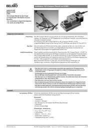
<strong>CR24</strong>-B3 Single <strong>room</strong> <strong>controller</strong>sBCTemperature <strong>controller</strong>s for <strong>single</strong> <strong>room</strong> applications with three analog outputs.• The analog output ao1 can be used in VAV applications to contol one or moreVAV <strong>controller</strong>s.• The analog output ao2 can be used to control a heating or cooling sequence(change-over).• The analog heating output ao3 supplies a 3-point signal.Technical dataNominal voltageAC 24 V 50/60 HzFor wire sizing3 VA, without actuatorsPower supply rangeAC 19.2...28.8 VControl characteristicsP / PI– P-band heating / cooling Selectable: 1.5 / 1.0 K or 3.0 / 2.0 KExternal temperature sensor (ai1) Type NTC, 5 kΩ, sensing range 10...45°CHeating setpointRange 15...36°C (default 21°C)– Energy hold off Heating 15°C / cooling 40°C– Stand-by Heating –2 K / cooling +3 KDead band1 KFrost limit temperature 10°COperation (<strong>CR24</strong>-B.. only)– Mode switch and status indication (LEDs) AUTO (green) – ECO (orange) – MAX (red)– Rotary knob for setpoint adjustment ±3 KInputs2 x analog, 3 x digital– External temperature sensor (ai1) Type NTC, 5 kΩ, sensing range 10...45°C– External setpoint shift (ai2) 0...10 V corresponds to 0...10 K– Digital inputs (di1, di2, di3) Contact rating 10 mAOutputs3 x analog– VAV system output (ao1) (0)2 ... 10 V, max. 5 mA– Heating / cooling output (ao2) 0...10 V, max. 5 mA– Heating output (ao3) 3-point, AC 24 V, max. source current 0.5 A / 10 VA(optimized for actuators with a running time ofapprox. 150 s)Communication port for field devices 2 x PP (for PC-Tool, MFT remote control etc.)HousingBaseplate: NCS2005-R80B light gray (correspondsapprox. to RAL 7035) / Cover: RAL 9003 signal whiteConnectionsTerminal block 1... 3: 2.5 mm2Terminal block 4...12: 1.5 mm2Ambient conditions– Operation 0...+50°C / 20...90% rH (without condensation)– Transport and storage –25...+70°C / 20...90% rH (without condensation)Standards– Protection class III Safety extra-low voltage– Degree of protection IP 30 to EN 60529– Mode of operation Type 1 to EN 60730-1– Software class A to EN 60730-1– EMC CE conformity to 89/336/EECDimensions (H x W x D)99 x 84 x 32 mmWeight105 g8Functions• Energy hold offIn energy saving mode, the <strong>room</strong> temperatureis reduced to building protection level,i.e. either the heating setpoint is significantlyreduced or the cooling setpoint is significantlyincreased, for instance in a <strong>room</strong> with anopen window.• Stand-byThe <strong>room</strong> temperature is reduced to standbylevel, i.e. either the heating setpoint isslightly reduced or the cooling setpoint isslightly increased, for instance in a <strong>room</strong>that is temporarily unoccupied.• FrostThe frost protection function is activated if theactual <strong>room</strong> temperature falls below 10°C.• Change-overChange-over heating or heating/cooling.• Chilled ceiling with dew point limitingIf the temperature falls below the dew point,the corresponding output is set to 0.• BoostThe <strong>room</strong> can be ventilated with themaximum volume flow (max) or heated orcooled with the maximum capacity.• External temperature sensorAn external temperature sensor can beconnected to the analog input ai1, for instancein order to measure the average<strong>room</strong> temperature in the exhaust air duct.• External setpoint shiftAn external DC 0...10 V signal at theanalog input ai2 can be used to shift thebasic setpoint 0...10 K, for instance for thesummer/winter compensation.These functions are described in detail onpages 11 to 17.Device variantType <strong>CR24</strong>-A3, same functionality as the<strong>CR24</strong>-B3 but without an operator panel..ENG-93001-93427-08.04-2M • Printed in Switzerland • ZSD • Subject to technical modifications
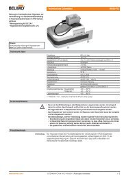
BC<strong>CR24</strong>-B3 Single <strong>room</strong> <strong>controller</strong>sWiring diagramConfigurationInputs3AC 24 V+~1 2 9 10 11 6 7 8NTCao3 ao2 ao1 U5 1 U5 20...10 V3 4 12 5ai/di1 di2 di3 ai2Outputs<strong>CR24</strong>-B3ai1 External temperature sensor 6 ao1 System output for <strong>Belimo</strong> VAV <strong>controller</strong>di1 Energy hold off 9/10 ao3 Heating (3-point)4 di2 Stand by 11 ao2 Heating / Cooling5 ai2 External setpoint shift Other connections12 di3 Boost / Change-over / Dew point 7 PP1 Diagnostics socket 18 PP2 Diagnostics socket 2DIPDefaultsettings1 P-band normal P-band wide2 max heating off max heating 80%3 Output ao2Heating4 Input di3Boost5 BoostTemperaturecontrolled6 Control characteristicPI1 2 3 4 5 6Output ao2Change-overCoolingInput di3Change-overDew pointBoost maxControl characteristicPPrincipal diagramY [V]ao310ao18.4 .V max HChange overao2Boostao1.V max2.Vmin0WHWCt R [°C]ENG-93001-93427-08.04-2M • Printed in Switzerland • ZSD • Subject to technical modificationsKeyY [V] Output voltage in volt ao.. Analog outputst R [°C] Room temperature in degrees centigrade max Maximum volume flowW H Heating setpoint max H Maximum volume flow heatingW C Cooling setpoint min Minimum volume flow9
OperationBCOperator level 1 – Operation Operating mode / Setpoint <strong>CR24</strong>-B.. onlyRotary knobfor setpoint adjustmentPotentiometer ±3 KStatus indication• MAX (red)• ECO (orange)• AUTO (green)Mode switch• MAX• ECO• AUTOMode switch and status indicationThere are three possible operating modes:• AUTO – optimum comfort modeThe <strong>room</strong> is heated, cooled or ventilated with the highest level ofcomfort, providing this is permitted by the external control signals. Allthe control functions (sequence control, boost function) are enabled.• ECO – optimum energy modeThe <strong>room</strong> is heated, cooled or ventilated with the stand-by settings,providing this is permitted by the external control signals. The heatingsetpoint is reduced in this mode (–2 K) and the cooling setpoint isincreased (+3 K). The <strong>room</strong> can be changed from "optimum energy"to "optimum comfort" in a very short time. Sequence control and theboost function are enabled. ECO mode is intended for <strong>room</strong>s that areonly irregularly occupied resp. at reduced demand.• MAX – boost functionThe <strong>room</strong> is ventilated with the maximum air volume or heated orcooled with the maximum capacity, providing this is permitted by theexternal control signals. Sequence control is disabled, but the boostand ventilation functions are active.The boost function gets deactiveded:– timer elapsed– setpoint reached (VAV fix 15 minutes)– change to another mode (AUTO or ECO)Operator level 2 – Configuration Application / Parameters all <strong>CR24</strong>-..DIP switches for configurationOrder-Nr. <strong>CR24</strong>-B2xxxxxONOFF1 2 3 4 5 62115W H36Basic setpoint adjustmentDIP switches for configurationDIP switches 1 and 2 (<strong>CR24</strong>-B1 and <strong>CR24</strong>-B2) or 1 to 6 (<strong>CR24</strong>-B3)Basic setpoint adjustmentPotentiometer 15...36°C (default 21°C)Label for settingsUsed to record the selected settings (DIP switches and basic setpoint).Label for settingsU5/ 2 U5/ 1Operator level 3 – Service Test / Simulation all <strong>CR24</strong>-..9101112Rotary knobfor control sequence simulationMesspunkteAnschlussklemmen2 112345678Internal function testPC-Tool connectionMeasuring point terminalsMeasuring points for all terminals (also during operation).Internal function testA comprehensive internal function test, including a nominal voltage test(AC 24 V), can be started for the <strong>controller</strong> with the mode switch. Thethree LEDs (status indication) indicate the voltage level and the states.Control sequence simulationThe connected actuators, and thus also the heating and cooling controlsequences, can be simulated independently of the <strong>room</strong> temperaturewith the rotary knob for adjusting the setpoint.PC-Tool connectionDiagnostics sockets 1 and 2 are used for PP communication with theconnected <strong>Belimo</strong> MFT actuators or VAV <strong>controller</strong>s. As a result, physicalaccess to the field devices can be dispensed with.ENG-93001-93427-08.04-2M • Printed in Switzerland • ZSD • Subject to technical modifications10
BCFunctionsIntroductionThe control functions define the behavior of the <strong>controller</strong> outputs and influence the currentsetpoint.Both the level of comfort and the energy saving potential can be significantly enhanced byinstalling suitable sensors on the input side.Please refer to the table on page 3 for an overview of the functions of the three basic <strong>CR24</strong>-B..types. These functions are described in detail below.Setpoint calculationOperating status Heating setpoint Cooling setpointComfortStand-byBasic setpoint W H± 3 K Setpoint adjustment+ Setpoint shift 0...10 VComfort heating setpoint W A– 2 K Stand-by offset heatingComfort heating setpoint W A+ 1 K Dead bandComfort heating setpoint W A+ 1 K Dead band+ 3 K Stand-by offset coolingEnergy hold off Fixed 15°C (building protection) Fixed 40°C (building protection)Frost Fixed 10°C Not relevantFrostY1020VAVEnergy hold offStand-byHeatingCoolingDead bandt RExamplesBasic setpoint W H±3 K Setpoing adjustmentSetpoint shift 0...10 VComfort heating setpoint W AComfortStand-byYY–2 K Stand-by offset heatingt R+3 K Stand-by offset coolingt R+1 K Dead band+1 K Dead bandENG-93001-93427-08.04-2M • Printed in Switzerland • ZSD • Subject to technical modifications23°C Comfort heating setpoint W A23°C Comfort heating setpoint W A11
FunctionsBCEnergy hold off Digital input di1 all <strong>CR24</strong>-..AC 24 V+~NTCEnergy hold offIf a local detector (e.g. a window switch) acts on the digital input di1and closes the corresponding contact, the <strong>room</strong> is adjusted to thebuilding protection settings in energy saving mode, in other words theheating setpoint is significantly reduced (15°C) or the cooling setpointsignificantly increased (40°C), though not sufficiently to cause damageto sensitive objects (plants, paintings etc.).10201 2Y [V]W A.V max.V min3ai/di1t R [°C]ZuEnergy hold off<strong>CR24</strong>-B..KeyY Output signalt R Room temperatureW A Current setpointTypical applications– A window switch at di1 stops all energy consumption from the momentthe window is opened until the lower or upper building protectionlimit is reached.– Higher-level override command, e.g. building management system.Notes– The minimum VAV output is set to 0 V instead of 2 V while energyhold off is active (forced closing in 2...10 V)– The mode switch (operator level 1) is deactivated while energy holdoff is active (input di1 takes priority).– If an external temperature sensor is used, the frost limit is monitoredby the internal sensor while energy hold off is active.– Due to the automatic sensor detection the change into Energy holdoff takes about 40 seconds.Stand-by Digital input di2 all <strong>CR24</strong>-..AC 24 V+~If a local detector (e.g. a motion detector) acts on the digital input di2and closes the corresponding contact, the <strong>room</strong> is adjusted to thestand-by settings, in other words the heating setpoint is reduced by 2 Kor the cooling setpoint is increased by 3 K.Stand-by4di2Typical applications– A motion detector, a light switch or another detector at di2 reducesthe energy consumption of unoccupied <strong>room</strong>s.– Higher-level override command, e.g. building management system.1 2<strong>CR24</strong>-B..1020Y [V]108.420Y [V]ao3ao1W Aao2W AStand-by.V max.Vminao1t R [°C].V maxVmint R [°C]Key. KeyY Output signalt R Room temperatureW A Current setpointVAV function: air volume in heating mode (Reheater) max heatingY Output signalt R Room temperatureW A Current setpoint<strong>CR24</strong>-B2 and <strong>CR24</strong>-B3 onlyIf the selected application requires an increased air volume for heating,e.g. for:– Providing or assisting heating with air.– Improving the air quality during heating.<strong>CR24</strong>-B2 configurationThe VAV function is configured using DIP switch 2.<strong>CR24</strong>-B3 configurationThe VAV function is configured using DIP switch 2.1 21 2 3 4 56ENG-93001-93427-08.04-2M • Printed in Switzerland • ZSD • Subject to technical modifications12
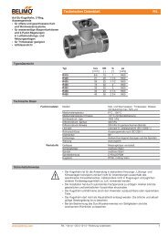
BCFunctionsExternal temperature sensor Analog input ai1 all <strong>CR24</strong>-..AC 24 V+~Externaltemperature sensorNTCAn external NTC temperature sensor can be connected to the analoginput ai1.Typical applicationA temperature sensor measures the average <strong>room</strong> temperature in theexhaust air duct.1 23ai/di1<strong>CR24</strong>-B..Notes– The internal sensor automatically detects the presence of an externalsensor.– It is possible to install an energy hold off switch simultaneously atdi1, in which case the system changes over to the internal sensor(see also "Energy hold off"). This permits the actual <strong>room</strong> temperatureto be monitored in order to protect the building.External setpoint shift Analog input ai2 all <strong>CR24</strong>-..AC 24 V+~Setpoint shift–0...10 VAn external DC 0...10 V signal at the analog input ai2 can be used toshift the basic setpoint 0...10 K (corresponds to 0...10 V).Typical application– Summer/winter compensation1 2W [°C]26215ai2<strong>CR24</strong>-B..NotesA negative shift can be achieved by adjusting the basic setpoint to therequired final setpoint, e.g. from 21°C (default value) to 16°C. In thiscase:– 0... 5 V corresponds to 16...21°C and– 5...10 V corresponds to 21...26°C (see diagram opposite).ENG-93001-93427-08.04-2M • Printed in Switzerland • ZSD • Subject to technical modifications16AC 24 V10+200~1 2Y [V]5.0W A10S [V]Air flusht R [°C]Air flush12di3KeyW SetpointS Shift signalAir flush Digital input di3 <strong>CR24</strong>-B2 onlyAutoAir flushKey<strong>CR24</strong>-B2Y Output signalt R Room temperatureW A Current setpointThe <strong>CR24</strong>-B2 <strong>controller</strong> allows override control at the digital inputdi3, to enable the <strong>room</strong> to be flushed with the maximum volume flow(max).Typical applications– Purging conference <strong>room</strong>s, hotel <strong>room</strong>s etc.(e.g. time switch-controlled)– Assisting smoke extraction– Controlling air quality (2-point signal)Notes– The VAV output ao1 is set to a fixed value of max (10 V).– The heating output ao3 remains in the normal control mode and continuesto be controlled by means of the heating sequence.13
FunctionsBCChange-over ao1 Digital input di2 <strong>CR24</strong>-B1 onlyAC 24 V+~ao1 U5 11 2 6 71 2 3 5Y U5+~CoolingHeatingFixed heating modeChange-over4di2<strong>CR24</strong>-B1<strong>Belimo</strong> actuatorIn change-over applications, the digital input di2 controls the VAV systemoutput ao1 of the <strong>CR24</strong>-B1 <strong>controller</strong>.Typical applicationsChange-over heating or heating/cooling.NoteThe <strong>CR24</strong>-B3 <strong>controller</strong> is suitable for applications that require both astand-by function and a change-over function.ConfigurationThe change-over function is configured using DIPswitch 21 2Y [V]10HeatingChange-overCooling20W At R [°C]KeyY Output signalt R Room temperatureW A Current setpointChange-over ao2 Digital input di3 <strong>CR24</strong>-B3 onlyAC 24 V10+1 2 11 70~1 2 3 5Y U5+~Y [V]Heatingao2 U5 1 di312Change-overW ACoolingt R [°C]Change-overCoolingHeatingKey<strong>CR24</strong>-B3<strong>Belimo</strong> actuatorY Output signalt R Room temperatureW A Current setpointIn change-over applications, the digital input di3 controls the commonheating/cooling output ao2 of the <strong>CR24</strong>-B3 <strong>controller</strong>.Typical applicationsChange-over heating or heating/cooling.Note– For chilled ceiling applications, refer to page 12.– The <strong>CR24</strong>-B1 <strong>controller</strong> is suitable for applications that only require achange-over function.ConfigurationThe change-over function is configured using DIPswitches 3 and 4.1 2 3 4 5 6ENG-93001-93427-08.04-2M • Printed in Switzerland • ZSD • Subject to technical modifications14
BCFunctionsBoost – max Digital input di3 <strong>CR24</strong>-B3 onlyAC 24 V+~AutoBoostThe <strong>CR24</strong>-B3 <strong>controller</strong> allows override control at the digital input di3,to enable the <strong>room</strong> to be ventilated with the maximum air flow (max).This function acts on all three analog outputs (see "Notes"). Room temperaturecontrol is deactivated in this mode (exception: frost protectionfunction).10201 2Y [V]ao3ao2W Aao1Boost – maxt R [°C]Boost12di3<strong>CR24</strong>-B3LegendeY Output signalt R Room temperatureW A Current setpointTypical applications– Purging conference <strong>room</strong>s, hotel <strong>room</strong>s etc.– Assisting smoke extraction– Free- or night coolingNotesThe boost function acts on the outputs as follows:– ao1 (VAV) 100% > 10 V ( max )– ao2 (heating / cooling) 0% > 0 V– ao3 (heating) 0% > closed (3-point)The boost function is deactivated by the following events:– Boost signal (di3) not active– Frost limit temperature (10°C) undershotConfigurationThis boost function is configured usingDIP switches 4 (boost on) and 5 (boost max ).1 2 3 4 5 6Boost – Temperature-controlled Digital input di3 <strong>CR24</strong>-B3 onlyAC 24 V+~AutoBoostThe <strong>CR24</strong>-B3 <strong>controller</strong> allows override control at the digital input di3,to enable the <strong>room</strong> to be heated or cooled with the maximum capacity.This function acts on all three analog outputs (see "Notes").Typical applicationsBoost– Rapid heating, rapid cooling– Cooling, morning boost etc.ENG-93001-93427-08.04-2M • Printed in Switzerland • ZSD • Subject to technical modifications1 2Y [V]1020ao3ao2W Aao112di3Boost – Temperature-controlled<strong>CR24</strong>-B3LegendeY Output signalt R [°C]t R Room temperatureW A Current setpointNotesThe boost function acts temperature-sensitive on the outputs as follows:– ao1 (VAV) 100% > 10 V ( max )– ao2 (heating / cooling) 100% > 10 V– ao3 (heating) 100% > open (3-point)To support reheater applications the VAV system output (ao1) gets activatedat the heating condition too.The boost function is deactivated by the following events:– Boost signal (di3) not active– Comfort setpoint (W A ) reachedThe air is always conditioned to the comfort setpoint W, even if stand-byis active, in order to facilitate <strong>room</strong> preconditioning.ConfigurationThis boost function is configured using DIP switches4 (boost on) and 5 (boost temperature-controlled).12 3 4 5 615
FunctionsBCChilled ceiling with dew point limiting Digital input di3 <strong>CR24</strong>-B3 onlyAC 24 V+~CoolingDew point undershotIf the temperature at the external dew point monitor (input di3) fallsbelow the dew point, output ao2 is set to 0 V.Typical applicationsChilled ceiling systems that require dew point limiting.Dew point1 2 11 7ao2 U5 1 di312<strong>CR24</strong>-B3ConfigurationThis function is configured using DIP switches 3and 4.1 2 3 4 5 61 2 3 5Y U5+~<strong>Belimo</strong> actuator10Y [V]ao20W ADew pointt R [°C]KeyY Output signalt R Room temperatureW A Current setpointChilled ceiling with dew point limiting and change-over Digital input di3 <strong>CR24</strong>-B3 onlyAC 24 V+~Dew pointCoolingDew point undershotHeatingChange-overIf the temperature at the external dew point monitor (input di3) fallsbelow the dew point, output ao2 is set to 0 V. Dew point limiting can becombined with the change-over function.Typical applicationsSwitchable heated/chilled ceiling systems that also require dew pointlimiting.101 2 11 71 2 3 5Y U5+0~Y [V]ao2 U5 1 di312Change-overW Aao2Dew pointt R [°C]<strong>CR24</strong>-B3<strong>Belimo</strong> actuatorKeyY Output signalt R Room temperatureW A Current setpointConfigurationThis function is configured using DIP switches 3and 4. 1 2 3 4 5 6ENG-93001-93427-08.04-2M • Printed in Switzerland • ZSD • Subject to technical modifications16
BCInstallation / DimensionsMechanical installation21 2 3 456 78311. Remove the housing cover.2. Pull out slightly the wall of the housing torelease the pcb.3. Remove the printed circuit board.Rotary knob for setpoint adjustmentLeft stopCamIf the rotary knob has been removed proceedas follows:1. Insert the rotary knob approximately halfway and turn it clockwise as far as thestop.2. Remove the knob and align it so that thecam is flush with the left stop.3. Insert the knob fully.Electrical installation1 2 3 4 5 6 7 81 2 3 4 5 6 7 8If space is limited or the cables that are usedare short, it is possible to release and removethe terminal blocks, then connect the cables,reinsert the prewired terminal blocks into thehousing from behind and snap them in tightlyagain.ENG-93001-93427-08.04-2M • Printed in Switzerland • ZSD • Subject to technical modifications6056910111256~2.5mm 2 AC 24V - -1.5mm 2 1.5mm 28499123456789032Dimensions [mm]17
Commissioning / ServiceBCCommissioning1. Assemble the baseplate of the housing and connect the cables (seepage 15).2. Configure the DIP switches on the printed circuit board according tothe required application.3. Assemble the printed circuit board on the baseplate of the housingand then mount the housing cover (see page 15).4. Switch on the nominal voltage (AC 24 V).5. Optional: start the test and simulation mode (see opposite).When the voltage is applied, the system starts operating normally inAUTO mode (unless the test and simulation mode is selected). Theactive operating status is determined primarily by the configuration ofthe DIP switches and the status of the inputsPower on behaviourAfter power on of the voltage supply the output gets initialized asfollows:– ao1 = 0 V– ao2 = 0 V– ao3 = closed (200 s)Subsequently the <strong>controller</strong> switches automatically to the control mode.Test and simulation modeAll <strong>controller</strong>s are supplied with two auxiliary programs for commissioningand servicing:– Internal function test– Control sequence simulationActivating test and simulation modeThe test and simulation mode of <strong>CR24</strong>-B.. <strong>controller</strong>s can be activatedeasily with the mode switch on the operator panel. With <strong>CR24</strong>-A.. <strong>controller</strong>s,the housing cover must be removed first.To activate test mode1. Set the mode switch to MAX– The red LED (MAX status indication) lights up2. Keep the mode switch pressed for ten seconds– The internal function test is activated (see below)To activate simulation mode3. Press the mode switch again briefly (for approximately one second)– The green LED (AUTO status indication) flashes– Control sequence simulation is activated (see below)Deactivating test and simulation modeThe test and simulation mode can be deactivated either by pressing themode switch again for ten seconds or by interrupting the power supply.It is also deactivated automatically 15 minutes after the last user action(auto-reset)..Internal function testNominal voltage (AC 24 V)LED(status indication)Heating1020–3Y [V]ao1–2–1X pHao3ao20W = Xao2X pC+1ao1+2–3 0+3Scenario A Scenario B Scenario CMAX red flash flash permanently onECO orange flash flash permanently onAUTO green permanently off flash permanently onControl sequence simulation22 VCooling+3t S [°C]Potentiometer (setpoint adjustment)for simulating the <strong>room</strong> temperatureLegendeY Output signalt S Simulated <strong>room</strong> temperatureX pH Heating sequenceX pC Cooling sequenceao.. Analog outputsThe internal function test tests the nominal voltage that is connected tothe <strong>controller</strong> (AC 24 V), in other words the complete electrical wiringsystem from the control cabinet to the <strong>controller</strong>.The three LEDs (status indication) indicate the voltage level (see opposite)and states during the test.NoteCase B and C do not need further attention. In case A (
BCNotesENG-93001-93427-08.04-2M • Printed in Switzerland • ZSD • Subject to technical modifications19
Air applicationsWater applicationsStandard actuators andspring-return actuators forair control dampers in HVACsystemsSafety actuators formotorizing fire and smokeextraction dampersVAV systems forindividual <strong>room</strong> air controlMixing actuators andmotorized ball valves forHVAC water circuitsGlobe valves and intelligentlinear actuators – also forleading makes of valveInnovation, Quality and Consultancy:A partnership for motorizing HVAC actuatorsContact the following for further information:<strong>Belimo</strong> HeadquartersCH BELIMO Holding AGBrunnenbachstrasse 18340 Hinwil, SwitzerlandTel. +41 (0)43 843 61 11Fax +41 (0)43 843 62 68info@belimo.chwww.belimo.ch<strong>Belimo</strong> SubsidiariesAT/ BELIMO AutomationHR/ Handelsgesellschaft m.b.H.HU/ Geiselbergstrasse 26–32SI/ 1110 Wien, AustriaSK Tel. +43 (0)1 749 03 61-0Fax +43 (0)1 749 03 61-99info@belimo.atAU BELIMO Actuators Pty. Ltd.Unit 10, 266 Osborne AvenueClayton South, VIC 3169AustraliaTel. +61 (0)3 9551 0201Fax +61 (0)3 9551 0215belimo@belimoactuators.comCA BELIMO Aircontrols (CAN), Inc.5716 Coopers Ave., Units 14&15Mississauga, Ontario L4Z 2E8CanadaTel. +1 (1)905 712 31 18Fax +1 (1)905 712 31 24webmaster@belimo.comCH BELIMO Automation AGSales SwitzerlandBrunnenbachstrasse 18340 Hinwil, SwitzerlandTel. +41 (0)43 843 62 12Fax +41 (0)43 843 62 66info@belimo.chwww.belimo.chDE BELIMO StellantriebeVertriebs GmbHWelfenstr. 27, Postfach 72 02 3070599 Stuttgart, GermanyTel. +49 (0)711 1 67 83-0Fax +49 (0)711 1 67 83-73info@belimo.dewww.belimo.deES BELIMO Ibéricade Servomotores, S.A.C/San Romualdo, 12–1428037 Madrid, SpainTel. +34 91 304 11 11Fax +34 91 327 25 39info@belimo.esFRGBHKPLSGBELIMO ServomoteursZ.A. de Courtry33, Rue de la Régale77181 Courtry, FranceTél. +33 (0)1 64 72 83 70Fax +33 (0)1 64 72 94 09mail@belimo.frBELIMO Automation UK LimitedShepperton Business ParkGovett Avenue, SheppertonMiddlesex TW17 8BAGreat BritainTel. +44 (0)1932 260460Fax +44 (0)1932 269222belimo@belimo.co.ukBELIMO Actuators Ltd.Room 208, 2/FNew Commerce Centre19 On Sum Street, Shatin, N.T.Hong KongTel. +852 26 87 17 16Fax +852 26 87 17 95info@belimo.com.hkBELIMO Silowniki S.A.ul. Zagadkl 2102-227 Warszawa, PolandTel. +48 (0)22 886 53 05Fax +48 (0)22 886 53 08info@belimo.plBELIMO Actuators Pte Ltd2, Jurong East Street 21#04-31F IMM BuildingSingapore 609601Tel. +65 6564 9828Fax +65 6564 9038info@belimo.com.sgUS BELIMO Aircontrols (USA), Inc.43 Old Ridgebury RoadP.O. Box 2928Danbury, CT 06810 USATel. +1 (1)203 791 99 15Fax +1 (1)203 792 29 67webmaster@belimo.comwww.belimo.com<strong>Belimo</strong> Representatives and AgenciesAEBELIMO TradingMiddle East OfficeP.O. Box 73885Dubai, U.A.E.Tel. +971 (0)4 295 9670Fax +971 (0)4 295 9680belimome@emirates.net.aeBG BELIMO Bulgaria Ltd.j.k. Lagera, 3 Smolyanska Str.bl. 56, entr. B, ap. 501612 Sofia, BulgariaTel. +3592 952 3470/1Fax +3592 545 995belimo@mbox.contact.bgCN BELIMO Actuators Ltd.Room 1305, Financial SquareNo. 333 Jiujiang Road200001 Shanghai, ChinaTel. +86 21 6360 8980Fax +86 21 6360 8981shanghai@belimo.chCN BELIMO BeijingRm 605, Beijing Hai ChangEdifice, 44, Liang Ma Qiao RoadChao Yang District100016 Beijing, ChinaTel. +86 10 6462 1382Fax +86 10 6462 1383beijing@belimo.chCZ BELIMO CZ (Ing. Ivar Mentzl)Charkovská 1610100 Praha 10, Czech RepublicTel. +420 (0)2 717 4 0 311Fax +420 (0)2 717 43 057info@belimo.czDK BELIMO A/SThomas Helstedsvej 7A8660 Skanderborg, DenmarkTel. +45 86 52 44 00Fax +45 86 52 44 88info@belimo.dkEE BELIMO Balticum ASTüri 10 d11313 Tallinn, EstoniaTel. +372 6 140 811Fax +372 6 140 812info@belimo.eeFI Oy Suomen BELIMO AbInsinöörinkatu 200810 Helsinki, FinlandTel. +358 (0)424 651 1Fax +358 (0)424 651 250belimo@belimo.fiGR/ BELIMO Air ControlsCY 29, Tagm. Plessa, KallitheaGR 17674 Athens, GreeceTel. +30 2 10 94 00 766Fax +30 2 10 94 00 767belimogr@tee.grIE Safegard Systems Ltd.Systems House, Unit 34Southern Cross Business ParkBray, Co Wicklow, IrelandTel. +353 (0)1 2761600Fax +353 (0)1 2761611info@safegard.ieIL Shemer RepresentationsP.O. Box 29656101 Yehud, IsraelTel. +972 3 536 51 67Fax +972 3 536 05 81shemer@shemerep.co.ilIN BELIMO Vitek Air ControlsC-114 Lancelot, First FloorS.V. Road, Borivali (West)Mumbai 400 092, IndiaTel. +91 22 5695 9439Fax +91 22 2806 2163bvac@bom2.vsnl.net.inIS Hitatækni ehf.Langholtsvegi 109104 Reykjavik, IcelandTel. +354 5 88 60 70Fax +354 5 88 60 71fridmar@hitataekni.isIT BELIMO Servomotori S.r.l.Via Stezzano, 524050 Zanica BG, ItalyTel. +39 035 67 26 82Fax +39 035 67 02 00info@belimo.itKR HANMO Corporation3rd Floor, Yeosam Bldg. 648-23Gangnam-Ku, Seoul, KoreaTel. +822 3453 8225Fax +822 3453 8228LB Energy Center (EC)Hamra, Leon Street, Shatilla,Bldg. 4th Floor,P.O. Box 113-6955Beirut, LebanonTel. +961 (0)1 35 38 23Fax +961 (0)1 35 38 23belimome@emirates.net.aeNL/ BELIMO Servomotoren BVBE/ BENELUXLUNOPostbus 300, 8160 AH EpeRadeweg 25, 8171 MD VaassenNetherlandsTel. +31 5 78 57 68 36Fax +31 5 78 57 69 15info@belimo.nlBELIMO Spjeldmotorer A/SKonowsgate 50192 Oslo 1, NorwayTel. +47 22 70 71 71Fax +47 22 70 71 70info@belimo.noPHRORUSESYTRTWUAZABELIMO Actuators PhilippinesRm.# 507 Anita Build., 5th Floor1300 Quezon Ave.,Cor.South Ave.1103 Quezon City, PhilippinesTel. +63 (2)373 5440Fax +63 (2)373 5424philippines@belimo.com.hkBELIMO Automatizări SRLCameliei nr. 5, corp B10851, sector 1, Bucuresti,RomaniaTel. +40 21 212 6993Fax +40 21 212 6995office@belimo.roBELIMO ServomotorsRussia Ltd.Nizhnyaya Pervomaiskaya,46 Bld.1, Office 303105203 Moscow, RussiaTel. +7 095 965 74 64Fax +7 095 965 74 73info@belimo.ruBELIMO ABHägerstens Allé 88129 37 Hägersten, SwedenTel. +46 (0)8 464 07 00Fax +46 (0)8 97 85 75info@belimo.sePhilippe A. JebranP.O. Box 7791Damascus, SyriaTel. +963 11 231 6586Fax +963 11 231 4052belimome@emirates.net.aeBELIMO Otomasyon A.S.Keyap Sitesi No. 20TR-34775 Y. DudulluIstanbul, TurkeyTel. +90 (0)216 527 98 70Fax +90 (0)216 527 98 71info@belimo.com.trChianseng Enterprise Co. Ltd.2F, No. 21, Tong Fong StreetTaipei, TaiwanTel. +886 2 27 08 77 80Fax +886 2 27 02 90 90taiwan@belimo.com.hkBELIMO Ukraine S.A.R.34-A, Ul. Yurkovskaya, Appt.No 2254080 Kiev, UkraineTel./Fax +380 44 463 7586comaster@belimo.kiev.ua<strong>Belimo</strong> Actuators Southern Africa ccP.O. Box 2483Alberton 1450, South AfricaTel. +27 (0)11 868 5681Fax +27 (0)11 900 2673belimo@mega.co.zaENG-93001-93427-08.04-2M • Printed in Switzerland • ZSD • Subject to technical modifications