CR24, single room controller - Belimo
CR24, single room controller - Belimo
CR24, single room controller - Belimo

You also want an ePaper? Increase the reach of your titles
YUMPU automatically turns print PDFs into web optimized ePapers that Google loves.
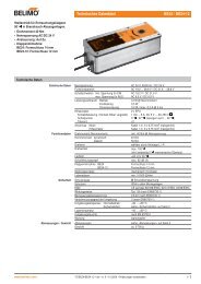
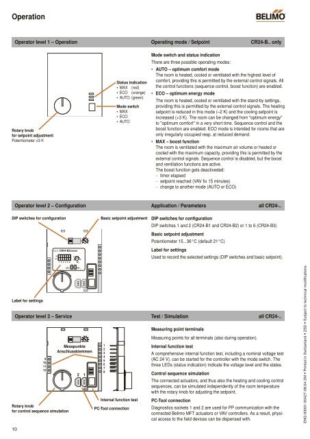
OperationBCOperator level 1 – Operation Operating mode / Setpoint <strong>CR24</strong>-B.. onlyRotary knobfor setpoint adjustmentPotentiometer ±3 KStatus indication• MAX (red)• ECO (orange)• AUTO (green)Mode switch• MAX• ECO• AUTOMode switch and status indicationThere are three possible operating modes:• AUTO – optimum comfort modeThe <strong>room</strong> is heated, cooled or ventilated with the highest level ofcomfort, providing this is permitted by the external control signals. Allthe control functions (sequence control, boost function) are enabled.• ECO – optimum energy modeThe <strong>room</strong> is heated, cooled or ventilated with the stand-by settings,providing this is permitted by the external control signals. The heatingsetpoint is reduced in this mode (–2 K) and the cooling setpoint isincreased (+3 K). The <strong>room</strong> can be changed from "optimum energy"to "optimum comfort" in a very short time. Sequence control and theboost function are enabled. ECO mode is intended for <strong>room</strong>s that areonly irregularly occupied resp. at reduced demand.• MAX – boost functionThe <strong>room</strong> is ventilated with the maximum air volume or heated orcooled with the maximum capacity, providing this is permitted by theexternal control signals. Sequence control is disabled, but the boostand ventilation functions are active.The boost function gets deactiveded:– timer elapsed– setpoint reached (VAV fix 15 minutes)– change to another mode (AUTO or ECO)Operator level 2 – Configuration Application / Parameters all <strong>CR24</strong>-..DIP switches for configurationOrder-Nr. <strong>CR24</strong>-B2xxxxxONOFF1 2 3 4 5 62115W H36Basic setpoint adjustmentDIP switches for configurationDIP switches 1 and 2 (<strong>CR24</strong>-B1 and <strong>CR24</strong>-B2) or 1 to 6 (<strong>CR24</strong>-B3)Basic setpoint adjustmentPotentiometer 15...36°C (default 21°C)Label for settingsUsed to record the selected settings (DIP switches and basic setpoint).Label for settingsU5/ 2 U5/ 1Operator level 3 – Service Test / Simulation all <strong>CR24</strong>-..9101112Rotary knobfor control sequence simulationMesspunkteAnschlussklemmen2 112345678Internal function testPC-Tool connectionMeasuring point terminalsMeasuring points for all terminals (also during operation).Internal function testA comprehensive internal function test, including a nominal voltage test(AC 24 V), can be started for the <strong>controller</strong> with the mode switch. Thethree LEDs (status indication) indicate the voltage level and the states.Control sequence simulationThe connected actuators, and thus also the heating and cooling controlsequences, can be simulated independently of the <strong>room</strong> temperaturewith the rotary knob for adjusting the setpoint.PC-Tool connectionDiagnostics sockets 1 and 2 are used for PP communication with theconnected <strong>Belimo</strong> MFT actuators or VAV <strong>controller</strong>s. As a result, physicalaccess to the field devices can be dispensed with.ENG-93001-93427-08.04-2M • Printed in Switzerland • ZSD • Subject to technical modifications10