Service Instructions - White Drive Products, Inc.
Service Instructions - White Drive Products, Inc.
Service Instructions - White Drive Products, Inc.

Create successful ePaper yourself
Turn your PDF publications into a flip-book with our unique Google optimized e-Paper software.
dimensions: mm [in]<br />
A)<br />
B)<br />
C)<br />
D)<br />
E)<br />
F)<br />
G)<br />
H)<br />
I)<br />
J)<br />
K)<br />
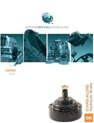
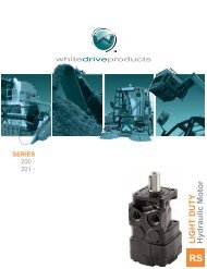
whitedriveproducts<br />
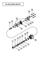
SERVICE INSTRUCTIONS FOR THE WR [255 & 256] SERIES MOTORS<br />
For Use With Seal Kit: 255222001<br />
PI255001 Rev. 4.09<br />
IMPORTANT NOTE: The WR(255/256) Series Motors depend on the correct orientation of parts as well as correct internal timing<br />
for proper motor operation. Before disassembling the motor, it is highly recommended that paint or a marker be used to make a<br />
“V” shaped set of lines from the endcover to the housing. This will aid in reassembling the motor components properly. It is also<br />
important that the steps involving internal parts timing be followed carefully to insure proper motor operation.<br />
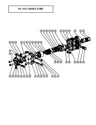
Remove all shaft related components from shaft (15) (i.e. keys, nuts). To aid in reassembly of the motor, make a “V” shaped set of<br />
lines from the endcover (11) to the housing using either paint or a marker. With shaft facing down, secure motor in vise by clamping<br />
on to the housing (5).<br />
Loosen and remove seven bolts (14) holding motor assembly together. Remove endcover (11). Remove body seal (4) and discard<br />
seal. Remove rotor set assembly (9), & wear plate (8). Remove body seals (4) from rotor assembly (9) and housing (5) and discard<br />
seals. Remove drive link pin (10) and drive link (7) from motor and lay aside.<br />
Gently tap shaft (15) upward through housing (5) and remove through rear of housing. Remove housing (5) from vise. Collect<br />
thrust bearing and thrust washer from the rear of the housing while turning the housing over. Secure the housing in the vise with<br />
the flange end facing up. Gently pry dust seal (1) from housing using a small screwdriver and a hammer. Gently remove shaft seal<br />
(2) with a small screwdriver and discard it.<br />
At this point, all parts should be cleaned in an oil-based solvent and dried using compressed air (For safety, observe all OSHA<br />
safety guidelines). All new seals should be lightly coated in clean oil prior to installation.<br />
Place shaft (15) on a clean flat surface with output end facing up. Place thrust bearing (6) then thrust washer (3) on the shaft. Install<br />
shaft seal (2) down onto shaft (15) making sure that lip on seal faces down. (See Figure (1) for shaft component orientation).<br />
NOTE: To turn the WR Series Motors to proper operation, the rotation code of the motor must be known. The rotation code of the<br />
motor is 255 (standard) 256 (reverse timed) – the first 3 digits of the model code. If the rotational code is not known, and if port<br />
‘A’ is pressurized , motors that are to have the shafts turning clockwise (as viewed from the shaft end) should be timed using the<br />
“255” series and motors that are to have the shafts turning counterclockwise (as viewed from shaft end) should be timed using the<br />
“256” series.<br />
Turn shaft (15) over so that output end of the shaft faces down. Lower drive link (7) into shaft making sure that the timing mark end<br />
of drive link faces up and that the timing mark on the end of the drive link (7) is aligned to the left of any short, open cutter slot on<br />
shaft (15).<br />
Turn housing (5) over so that the pilot of housing faces down and secure housing (5) in vise. Without disturbing the shaft seal (2),<br />
and drive link (7), carefully lower shaft assembly into housing. Apply pressure using an arbor press or a rubber mallet to make<br />
sure that the shaft end is flush or slightly lower than the housing bolt hole surface.<br />
Place a body seal (4) in groove in the rear surface of the housing (5). Place wear plate (8) on housing. Make sure that the seven<br />
valving slots on the wear plate line up with the seven bolt holes on the housing (5).<br />
Place a body seal (4) in the groove in the face of the rotor assembly (9). With the seal groove surface on the rotor assembly facing<br />
wear plate, lower rotor assembly (9) onto drive link (7) making sure that the timing mark on drive link is aligned with a peak on the<br />
rotor (9) for 256 series, or with a valley on the rotor (9) for 255 series (See Figure (2)). After assembling the rotor assembly on the<br />
drive link rotate the rotor assembly to line up the assembly bolt holes. Insert drive link pin (10) into end of drive link (7) making sure<br />
that concave or the indented end faces up.<br />
Place remaining body seal (4) in groove in endcover (11). Place endcover (11) onto motor making sure that end of drive link pin<br />
(10) is in hole in center of end cover (11). There is no specific orientation to assemble the end cover on the motor.<br />
Install one washer (13) on each bolt (14) from the threaded end side. Insert seven assembly bolts (14) with washers (13) into bolt<br />
holes and pre-torque to 13.6 Nm [10 ft. lb.]. Using a crisscross pattern, final torque bolts to 60 Nm [44 ft. lb.].<br />
Remove motor from vise and place on work surface with shaft (15) facing up. Making sure that lip on dust seal (1) faces up, place<br />
dust seal (1) over shaft (15). Using a sleeve and hammer, carefully drive dust seal (1) into place.<br />
<strong>White</strong> <strong>Drive</strong> <strong>Products</strong>, <strong>Inc</strong>. • P.O. Box 1127 • Hopkinsville, KY 42241 • Phone: 270.885.1110 • Fax: 270.886.8462
DUST SEAL SHAFT SEAL THRUST BEARING<br />
HOUSING THRUST WASHER<br />
8<br />
7<br />
VALLEY<br />
ON ROTOR<br />
PEAK ON ROTOR<br />
TIMING MARK<br />
ON DRIVE LINK<br />
TIMING MARK<br />
ON DRIVE LINK<br />
FIGURE 1 FIGURE 2<br />
9<br />
5<br />
1<br />
4<br />
10<br />
3<br />
4<br />
2<br />
12<br />
16<br />
255 TIMING<br />
1. * Dust Seal<br />
2. * Shaft Seal<br />
3. * Thrust Washer<br />
4. * Body Seals (3)<br />
5. Housing<br />
6. Thrust Bearing<br />
7. <strong>Drive</strong> Link<br />
8. Wear Plate<br />
9. Rotor Assembly<br />
10. <strong>Drive</strong> Link Pin<br />
11. Endcover<br />
12. Endcover Plug<br />
13. Assembly Bolt Washers (7)<br />
14. Assembly Bolts (7)<br />
15. Shaft<br />
16. Shaft Key<br />
* Contained in Seal Kit 255222001<br />
<strong>White</strong> <strong>Drive</strong> <strong>Products</strong>, <strong>Inc</strong>. • P.O. Box 1127 • Hopkinsville, KY 42241 • Phone: 270.885.1110 • Fax: 270.886.8462<br />
11<br />
6<br />
14<br />
4<br />
13<br />
15<br />
256 TIMING