STEEL BUILDINGS IN EUROPE Single-Storey Steel Buildings Part 2
STEEL BUILDINGS IN EUROPE Single-Storey Steel Buildings Part 2
STEEL BUILDINGS IN EUROPE Single-Storey Steel Buildings Part 2

Create successful ePaper yourself
Turn your PDF publications into a flip-book with our unique Google optimized e-Paper software.
<strong>STEEL</strong> <strong>BUILD<strong>IN</strong>GS</strong> <strong>IN</strong> <strong>EUROPE</strong><br />
<strong>Single</strong>-<strong>Storey</strong> <strong>Steel</strong> <strong>Buildings</strong><br />
<strong>Part</strong> 2: Concept Design
<strong>Single</strong>-<strong>Storey</strong> <strong>Steel</strong> <strong>Buildings</strong><br />
<strong>Part</strong> 2: Concept Design
2 - ii
<strong>Part</strong> 2: Concept Design<br />
FOREWORD<br />
This publication is a second part of a design guide, <strong>Single</strong>-<strong>Storey</strong> <strong>Steel</strong> <strong>Buildings</strong>.<br />
The 11 parts in the <strong>Single</strong>-<strong>Storey</strong> <strong>Steel</strong> <strong>Buildings</strong> guide are:<br />
<strong>Part</strong> 1: Architect’s guide<br />
<strong>Part</strong> 2: Concept design<br />
<strong>Part</strong> 3: Actions<br />
<strong>Part</strong> 4: Detailed design of portal frames<br />
<strong>Part</strong> 5: Detailed design of trusses<br />
<strong>Part</strong> 6: Detailed design of built up columns<br />
<strong>Part</strong> 7: Fire engineering<br />
<strong>Part</strong> 8: Building envelope<br />
<strong>Part</strong> 9: Introduction to computer software<br />
<strong>Part</strong> 10: Model construction specification<br />
<strong>Part</strong> 11: Moment connections<br />
<strong>Single</strong>-<strong>Storey</strong> <strong>Steel</strong> <strong>Buildings</strong> is one of two design guides. The second design guide is<br />
Multi-<strong>Storey</strong> <strong>Steel</strong> <strong>Buildings</strong>.<br />
The two design guides have been produced in the framework of the European project<br />
“Facilitating the market development for sections in industrial halls and low rise<br />
buildings (SECHALO) RFS2-CT-2008-0030”.<br />
The design guides have been prepared under the direction of Arcelor Mittal, Peiner<br />
Träger and Corus. The technical content has been prepared by CTICM and SCI,<br />
collaborating as the <strong>Steel</strong> Alliance.<br />
2 - iii
<strong>Part</strong> 2: Concept Design<br />
2 - iv
<strong>Part</strong> 2: Concept Design<br />
Contents<br />
2 - v<br />
Page No<br />
FOREWORD iii<br />
SUMMARY vi<br />
1 <strong>IN</strong>TRODUCTION 1<br />
1.1 Hierarchy of design decisions 1<br />
1.2 Architectural design 2<br />
1.3 Choice of building type 6<br />
1.4 Design requirements 9<br />
1.5 Sustainability 12<br />
2 CASE STUDIES ON S<strong>IN</strong>GLE STOREY <strong>BUILD<strong>IN</strong>GS</strong> 14<br />
2.1 Manufacturing hall, Express Park, UK 14<br />
2.2 Supermarket, Esch, Luxembourg 15<br />
2.3 Motorway Service station, Winchester, UK 16<br />
2.4 Airbus Industrie hanger, Toulouse, France 17<br />
2.5 Industrial hall, Krimpen aan den Ijssel, Netherlands 17<br />
2.6 Distribution Centre and office, Barendrecht, Netherlands 18<br />
3 CONCEPT DESIGN OF PORTAL FRAMES 19<br />
3.1 Pitched roof portal frame 20<br />
3.2 Frame stability 22<br />
3.3 Member stability 23<br />
3.4 Preliminary Design 25<br />
3.5 Connections 27<br />
3.6 Other types of portal frame 29<br />
4 CONCEPT DESIGN OF TRUSS <strong>BUILD<strong>IN</strong>GS</strong> 35<br />
4.1 Introduction 35<br />
4.2 Truss members 36<br />
4.3 Frame stability 38<br />
4.4 Preliminary design 39<br />
4.5 Rigid frame trusses 40<br />
4.6 Connections 40<br />
5 SIMPLE BEAM STRUCTURES 42<br />
6 BUILT-UP COLUMNS 43<br />
7 CLADD<strong>IN</strong>G 45<br />
7.1 <strong>Single</strong>-skin trapezoidal sheeting 45<br />
7.2 Double-skin system 45<br />
7.3 Standing seam sheeting 47<br />
7.4 Composite or sandwich panels 47<br />
7.5 Fire design of walls 47<br />
8 PRELIM<strong>IN</strong>ARY DESIGN OF PORTAL FRAMES 49<br />
8.1 Introduction 49<br />
8.2 Estimation of member sizes 49<br />
REFERENCES 52
<strong>Part</strong> 2: Concept Design<br />
SUMMARY<br />
This publication presents information necessary to assist in the choice and use of steel<br />
structures at the concept design stage in modern single storey buildings. The primary<br />
sector of interest is industrial buildings, but the same information may also be used in<br />
other sectors, such as commercial, retail and leisure. The information is presented in<br />
terms of the design strategy, anatomy of building design and structural systems that are<br />
relevant to the single storey buildings. Other parts in the guide cover loading, the<br />
concept design of portal frames, the concept design of trusses and cladding.<br />
2 - vi
<strong>Part</strong> 2: Concept Design<br />
1 <strong>IN</strong>TRODUCTION<br />
<strong>Single</strong> storey buildings use steel framed structures and metallic cladding of all<br />
types. Large open spaces can be created, which are efficient, easy to maintain<br />
and are adaptable as demand changes. <strong>Single</strong> storey buildings are a “core”<br />
market for steel. However, the use of steel in this type of construction varies in<br />
each European country.<br />
<strong>Single</strong> storey buildings tend to be large enclosures, but may require space for<br />
other uses, such as offices, handling and transportation, overhead cranes etc.<br />
Therefore, many factors have to be addressed in their design.<br />
Increasingly, architectural issues and visual impact have to be addressed and<br />
many leading architects are involved in modern single storey buildings.<br />
This section describes the common forms of single storey buildings that may<br />
be designed and their range of application. Regional differences may exist<br />
depending on practice, regulations and capabilities of the supply chain.<br />
1.1 Hierarchy of design decisions<br />
The development of a design solution for a single storey building, such as a<br />
large enclosure or industrial facility is more dependent on the activity being<br />
performed and future requirements for the space than other building types, such<br />
as commercial and residential buildings. Although these building types are<br />
primarily functional, they are commonly designed with strong architectural<br />
involvement dictated by planning requirements and client ‘branding’.<br />
The following overall design requirements should be considered in the concept<br />
design stage of industrial buildings and large enclosures, depending on the<br />
building form and use:<br />
� Space use, for example, specific requirements for handling of materials or<br />
components in a production facility<br />
� Flexibility of space in current and future use<br />
� Speed of construction<br />
� Environmental performance, including services requirements and thermal<br />
performance<br />
� Aesthetics and visual impact<br />
� Acoustic isolation, particularly in production facilities<br />
� Access and security<br />
� Sustainability considerations<br />
� Design life and maintenance requirements, including end of life issues.<br />
To enable the concept design to be developed, it is necessary to review these<br />
considerations based on the type of single storey building. For example, the<br />
requirements for a distribution centre will be different to a manufacturing<br />
2 - 1
<strong>Part</strong> 2: Concept Design<br />
facility. A review of the importance of various design issues is presented in<br />
Table 1.1 for common building types.<br />
Table 1.1 Important design factors for single storey buildings<br />
Type of single<br />
storey buildings<br />
High bay<br />
warehouses<br />
Space requirements<br />
Flexibility of use<br />
2 - 2<br />
Speed of construction<br />
Access and Security<br />
Standardization of components<br />
Environmental performance<br />
Aesthetics and visual impact<br />
�� �� �� �� �� � �<br />
Manufacturing facility �� �� � �� � � �� �<br />
Distribution centres �� �� �� �� �� � � �<br />
Retail superstores �� �� � �� �� �� �� �<br />
Storage/cold storage � � � �� � �� � ��<br />
Office and light<br />
manufacturing<br />
Acoustic isolation<br />
Design life, maintenance and re-use<br />
� � � � � �� � �� �<br />
Processing facility � � �� � � �� �<br />
Leisure centres � �� � � � �� �� � �<br />
Sports halls �� �� � � � �� �� �<br />
Exhibition halls �� �� � �� � �� �� �� �<br />
Aircraft hangars �� � � �� � � � � �<br />
Legend: No tick = Not important � = important �� = very important<br />
1.2 Architectural design<br />
Modern single storey buildings using steel are both functional in use and are<br />
designed to be architecturally attractive. Various examples are presented below<br />
together with a brief description of the design concept. A variety of structural<br />
solutions are possible, which are presented in Sections 2 and 3.<br />
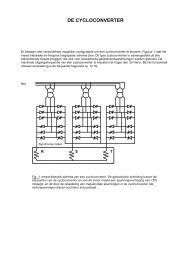
1.2.1 Building form<br />
The basic structural form of a single storey building may be of various generic<br />
types, as shown in Figure 1.1. The figure shows a conceptual cross-section<br />
through each type of building, with notes on the structural concept, and typical<br />
forces and moments due to gravity loads.
<strong>Part</strong> 2: Concept Design<br />
Simple beam<br />
Portal frame<br />
Truss<br />
Portal truss<br />
Figure 1.1 Structural concepts<br />
The basic design concepts for each structural type are described below:<br />
Simple roof beam, supported on columns.<br />
The span will generally be modest, up to approximately 20 m. The roof beam<br />
may be pre-cambered. Bracing will be required in the roof and all elevations, to<br />
provide in-plane and longitudinal stability.<br />
Portal frame<br />
A portal frame is a rigid frame with moment resisting connections to provide<br />
stability in-plane. A portal frame may be single bay or multi bay as shown in<br />
Figure 1.2. The members are generally plain rolled sections, with the resistance<br />
of the rafter enhanced locally with a haunch. In many cases, the frame will<br />
have pinned bases.<br />
Stability in the longitudinal direction is provided by a combination of bracing<br />
in the roof, across one or both end bays, and vertical bracing in the elevations.<br />
If vertical bracing cannot be provided in the elevations (due to industrial doors,<br />
for example) stability is often provided by a rigid frame within the elevation.<br />
Trusses<br />
Truss buildings generally have roof bracing and vertical bracing in each<br />
elevation to provide stability in both orthogonal directions, as in Figure 1.4.<br />
The trusses may take a variety of forms, with shallow or steep external roof<br />
slopes.<br />
2 - 3
<strong>Part</strong> 2: Concept Design<br />
A truss building may also be designed as rigid in-plane, although it is more<br />
common to provide bracing to stabilise the frame.<br />
Other forms of construction<br />
Built–up columns (two plain beams, connected to form a compound column)<br />
are often used to support heavy loads, such as cranes. These may be used in<br />
portalised structures, but are often used with rigid bases, and with bracing to<br />
provide in-plane stability.<br />
External or suspended support structures may be used, as illustrated in<br />
Figure 1.6, but are relatively uncommon.<br />
Figure 1.2 Multi bay portal frame structure<br />
2 - 4
<strong>Part</strong> 2: Concept Design<br />
Figure 1.3 Use of curved cellular beams in a portal frame<br />
Figure 1.4 Roof trusses and built-up columns<br />
2 - 5
<strong>Part</strong> 2: Concept Design<br />
Figure 1.5 Curved cellular beams used in a leisure centre<br />
Figure 1.6 External structure supporting a single storey building<br />
1.3 Choice of building type<br />
Portal frames are considered to be a highly cost-effective way to provide a<br />
single storey enclosure. Their efficiency depends on the method of analysis,<br />
and the assumptions that are made regarding the restraint to the structural<br />
members, as shown in Table 1.2. The assumptions about member stability may<br />
vary between countries.<br />
2 - 6
<strong>Part</strong> 2: Concept Design<br />
Table 1.2 Efficient portal frame design<br />
Most Efficient Less Efficient<br />
Analysis using elastic-plastic software Elastic analysis<br />
Cladding considered to restrain the flange of<br />
the purlins and side rails<br />
Purlins and side rails used to restrain both<br />
flanges of the hot-rolled steelwork<br />
2 - 7<br />
Purlins and side rails unrestrained<br />
The inside flange of the hot rolled steelwork is<br />
unrestrained<br />
Nominal base stiffness utilised Nominal base stiffness ignored<br />
The reasons for choosing simple beam structures, portal frames or trusses are<br />
shown in Table 1.3.<br />
Table 1.3 Comparison of basic structural forms for single storey buildings<br />
Simple beam Portal frame Truss<br />
Advantages<br />
Simple design Long span Very long spans possible<br />
Disadvantages<br />
Designed to be stable<br />
in-plane<br />
Member sizes and haunches<br />
may be optimised for<br />
efficiency<br />
Relatively short span Software required for efficient<br />
design<br />
Bracing needed for in-plane<br />
stability<br />
No economy due to continuity<br />
Limited to relatively light<br />
vertical loading, and modest<br />
cranes to avoid excessive<br />
deflections<br />
Heavy loads may be carried<br />
Modest deflection<br />
Generally more expensive<br />
fabrication<br />
Generally bracing is used for<br />
in-plane stability<br />
1.3.1 Cladding types<br />
The main types of roofing and wall cladding used in single storey buildings are<br />
described as follows:<br />
Roofing<br />
� ‘Built-up’ or double layer roofing spanning between secondary members<br />
such as purlins.<br />
� Composite panels (also known as sandwich panels) spanning between<br />
purlins.<br />
� Deep decking spanning between main frames, supporting insulation, with<br />
an external metal sheet or waterproof membrane.<br />
Walls<br />
� Sheeting, orientated vertically and supported on side rails.<br />
� Sheeting or structural liner trays spanning horizontally between columns.<br />
� Composite or sandwich panels spanning horizontally between columns,<br />
eliminating side rails.<br />
� Metallic cassette panels supported by side rails.
<strong>Part</strong> 2: Concept Design<br />
Different forms of cladding may be used together for visual effect in the same<br />
façade. Examples are illustrated in Figure 1.7, Figure 1.8 and Figure 1.9.<br />
Brickwork is often used as a “dado” wall below the level of the windows for<br />
impact resistance, as shown in Figure 1.8.<br />
Figure 1.7 Horizontal spanning sheeting<br />
Figure 1.8 Large windows and use of composite panels with “dado” brick<br />
wall<br />
2 - 8
<strong>Part</strong> 2: Concept Design<br />
Figure 1.9 Horizontal composite panels and ‘ribbon’ windows<br />
1.4 Design requirements<br />
Design requirements for single-span buildings are presented as follows:<br />
1.4.1 Actions<br />
Permanent actions<br />
Permanent actions are the self weight of the structure, secondary steelwork and<br />
cladding. These may be calculated from EN 1991-1-1.<br />
Typical weights of materials used in roofing are given in Table 1.4.<br />
If a roof only carries normal imposed roof loads (i.e. no suspended machinery<br />
or similar) the self weight of a steel frame is typically 0,2 to 0,4 kN/m 2 when<br />
expressed over the plan area of the roof.<br />
2 - 9
<strong>Part</strong> 2: Concept Design<br />
Table 1.4 Typical weights of roofing materials<br />
Material Weight (kN/m 2 )<br />
<strong>Steel</strong> roof sheeting (single skin) 0,07 – 0,12<br />
Aluminium roof sheeting (single skin) 0,04<br />
Insulation (boards, per 25 mm thickness) 0,07<br />
Insulation (glass fibre, per 100 mm thickness) 0,01<br />
Liner trays (0,4 mm – 0,7 mm thickness) 0,04 – 0,07<br />
Composite panels (40 mm – 100 mm thickness) 0,1 – 0,15<br />
<strong>Steel</strong> purlins (distributed over the roof area) 0,03<br />
<strong>Steel</strong> decking 0,2<br />
Three layers of felt with chippings 0,29<br />
Slates 0,4 – 0,5<br />
Tiling (clay or plain concrete tiles ) 0,6 – 0,8<br />
Tiling (concrete interlocking) 0,5 – 0,8<br />
Timber battens 0,1<br />
Variable actions<br />
Variable actions should be determined from the following Eurocode parts:<br />
EN 1991-1-1 for imposed roof loads<br />
EN 1991-1-3 for snow loads<br />
EN 1991-1-4 for wind actions<br />
EN 1991-1-1 recommends a uniform load of 0,4 kN/m 2 for roofs not accessible<br />
except for normal maintenance and repair (category H). A point load of 1,0 kN<br />
is also recommended, but this will only affect the design of the sheeting and<br />
not the main structural elements.<br />
EN 1991-1-3 includes several possible load cases due to snow, including<br />
uniform snow and drifted snow, which typically occurs in valleys, behind<br />
parapets etc. There is also the possibility of exceptional snow loads.<br />
The value of the snow load depends on the building’s location and height<br />
above sea level.<br />
EN 1991-1-4 is used to determine wind actions, which depend on altitude,<br />
distance from the sea and the surrounding terrain.<br />
The determination of loads is covered in detail in a separate chapter of this<br />
guidance.<br />
Loading due to services will vary greatly, depending on the use of the building.<br />
A typical service loading may be between 0,1 and 0,25 kN/m 2 as measured on<br />
plan, depending on the use of the building. If air handling units or other<br />
significant equipment loading is to be supported, the service load should be<br />
calculated accurately.<br />
1.4.2 Temperature effects<br />
In theory, steel frames expand and contract with changes in temperature. Often,<br />
the temperature change of the steelwork itself is much lower than any change<br />
2 - 10
<strong>Part</strong> 2: Concept Design<br />
in the external temperature, because it is protected. It is generally accepted that<br />
the movement available when using bolts in clearance holes is sufficient to<br />
absorb any movement due to temperature.<br />
It is recommended that expansion joints are avoided if possible, since these are<br />
expensive and can be difficult to detail correctly to maintain a weather-tight<br />
external envelope. In preference to providing expansion joints, the frame may<br />
be analysed including the design effects of a temperature change. The<br />
temperature actions may be determined from EN 1991-1-5, and combinations<br />
of actions verified in accordance with EN 1990. In most cases, the members<br />
will be found to be adequate.<br />
Common practice for industrial buildings in Northern Europe, in the absence of<br />
calculations, is that expansion joints do not need to be provided unless the<br />
length of the building exceeds 150m. In warmer climates, common practice is<br />
to limit the length to around 80m. Although it is good practice to position the<br />
vertical bracing mid-way along the length of the structure, to allow free<br />
expansion at both ends of the structure, this is not always possible or desirable.<br />
Many orthodox industrial structures have bracing at each end, or at intervals<br />
along the length of the structure, with no expansion joints, and perform<br />
perfectly well.<br />
1.4.3 Thermal performance and air-tightness<br />
The thermal performance of single storey buildings and enclosures is<br />
increasingly important because of their large surface area. Thermal<br />
performance also includes prevention of excessive heat loss due to air<br />
infiltration, known as ‘air-tightness’.<br />
There is a strong inter-relationship between the types of cladding and thermal<br />
performance. Modern steel cladding systems, such as composite panels, can<br />
achieve U-values of less than 0,2 W/(m 2 K).<br />
Air-tightness is assessed based on full-scale tests after completion of the<br />
structure in which the internal volume is pressurised - generally to 50 Pa (this<br />
may vary in different countries). The volume of air that is lost is measured and<br />
must be less than a given figure – typically 10m 3 /m 2 /hour.<br />
1.4.4 Fire resistance<br />
Fire resistance requirements are dependent on a wide range of issues, such as<br />
the combustible contents of the building, effective means of escape and<br />
occupation density (e.g. for public spaces). Generally, in single storey<br />
buildings, the means of escape is good and most enclosures are designed for<br />
fire resistance periods of 30 minutes or less. An exception may be office space<br />
attached to these buildings.<br />
National regulations are often more concerned to limit fire spread to adjacent<br />
structures, rather than the performance of the particular structure, especially if<br />
the structure is an industrial building. The determining factor is often the<br />
distance to the adjacent boundary. If such regulations apply, the usual solution<br />
is to ensure the integrity of the elevation that is adjacent to the boundary. This<br />
is commonly ensured by providing cladding with fire resistance, and ensuring<br />
that the primary supporting structure remains stable – by protecting the<br />
2 - 11
<strong>Part</strong> 2: Concept Design<br />
steelwork on that elevation, and designing the elevation steelwork to resist the<br />
forces applied by any other parts of the structure that have collapsed.<br />
For many building types, such as exhibition halls, fire engineering analysis<br />
may be carried to out demonstrate that active protection measures are effective<br />
in reducing fire temperatures to a level where the structure is able to resist the<br />
applied loads in the fire scenario without additional fire protection.<br />
1.5 Sustainability<br />
Sustainable construction must address three goals:<br />
• Environmental criteria<br />
• Economic criteria<br />
• Social criteria<br />
These three criteria are met by construction in steel:<br />
Environmental criteria<br />
<strong>Steel</strong> is one of the most recovered and recycled materials. Some 84% is<br />
recycled with no loss of strength or quality, and 10% reused. Before<br />
demolishing a structure, extending a building’s life is generally more<br />
beneficial. This is facilitated by steel construction, since large column-free<br />
spaces give flexibility for change in use. Advances in the manufacturing of raw<br />
materials means that less water and energy is used in production, and allows<br />
for significant reductions in noise, particle and CO2 emissions.<br />
Economic criteria<br />
<strong>Steel</strong> construction brings together the various elements of a structure in an<br />
integrated design. The materials are manufactured, fabricated and constructed<br />
using efficient production processes. The use of material is highly optimised<br />
and waste virtually eliminated. The structures themselves are used for all<br />
aspects of modern life, including logistics, retail, commercial, and<br />
manufacturing, providing the infrastructure on which society depends. <strong>Steel</strong><br />
construction provides low investment costs, optimum operational costs and<br />
outstanding flexibility of building use, with high quality, functionality,<br />
aesthetics and fast construction times.<br />
Social criteria<br />
The high proportion of offsite fabrication in steel buildings means that working<br />
conditions are safer, controlled and protected from the weather. A fixed<br />
location for employees helps to develop communities, family life and the skills.<br />
<strong>Steel</strong> releases no harmful substances into the environment, and steel buildings<br />
provide a robust, safe solution.<br />
<strong>Single</strong> storey structures<br />
The design of low-rise buildings is increasingly dependent on aspects of<br />
sustainability defined by criteria such as:<br />
� Efficient use of materials and responsible sourcing of materials<br />
� Elimination of waste in manufacturing and in construction processes<br />
2 - 12
<strong>Part</strong> 2: Concept Design<br />
� Energy efficiency in building operation, including improved air-tightness<br />
� Measures to reduce water consumption<br />
� Improvement in indoor comfort<br />
� Overall management and planning criteria, such as public transport<br />
connections, aesthetics or preservation of ecological value.<br />
<strong>Steel</strong> framed buildings can be designed to satisfy all these criteria. Some of the<br />
recognised sustainability benefits of steel are:<br />
� <strong>Steel</strong> structures are robust, with a long life. Properly detailed and<br />
maintained, steel structures can be used indefinitely<br />
� 10% of structural steel sections are re-used [1]<br />
� Approximately 95% of structural steel sections are recycled<br />
� <strong>Steel</strong> products can potentially be dismantled and reused, particularly<br />
modular components or steel frames<br />
� <strong>Steel</strong> structures are lightweight, requiring smaller foundations than other<br />
materials<br />
� <strong>Steel</strong> is manufactured efficiently in factory controlled processes<br />
� All waste is recycled in manufacture and no steel waste is produced on site<br />
� Construction in steel maximises the opportunity and ease of extending<br />
buildings and change of use<br />
� High levels of thermal insulation can be provided in the building envelope<br />
� Prefabricated construction systems are rapidly installed and are much safer<br />
in terms of the construction processes.<br />
Different sustainability assessment measures exist in various European<br />
countries [2] .<br />
2 - 13
<strong>Part</strong> 2: Concept Design<br />
2 CASE STUDIES ON S<strong>IN</strong>GLE STOREY<br />
<strong>BUILD<strong>IN</strong>GS</strong><br />
The following case studies illustrate the use of steel in single storey buildings,<br />
such as show rooms, production facilities, supermarkets and similar buildings.<br />
2.1 Manufacturing hall, Express Park, UK<br />
Figure 2.1 Portal frame during construction<br />
The portal frame shows in Figure 2.1 forms part of a new production facility<br />
for Homeseeker Homes, who manufacture portable homes for residential parks.<br />
The project comprises a 150 m long production hall, an adjacent office<br />
building and a separate materials storage building.<br />
The production hall is a duo-pitch portal frame with a 35 m clear span and a<br />
height of 9 m to the underside of the haunch. The production hall has to<br />
accommodate four overhead gantry cranes, each with a safe working load of<br />
5 t. Two cranes may be used in tandem, and the forces arising from this<br />
loading case had to be carefully considered. The longitudinal surge from the<br />
cranes is accommodated by bracing in the elevations, which also provides<br />
longitudinal stability. There are no expansion joints in the production hall –<br />
the bracing was designed to resist any loads from thermal expansion.<br />
To control the lateral deflection at the level of the crane rail, the frames, at 6 m<br />
centres, are rather stiffer than an equivalent structure without cranes. The<br />
columns are 762 mm deep and the rafters 533 mm deep.<br />
The gable frames are portal frames instead of a braced gable frame constructed<br />
from columns and simply-supported rafters, to reduce the differential<br />
deflection between the end frame and the penultimate frame.<br />
2 - 14
<strong>Part</strong> 2: Concept Design<br />
The facility is relatively close to the site boundary, which meant that the<br />
boundary elevations had to have special consideration. A fire load case was<br />
analysed and the column bases designed to resist the overturning moment from<br />
grossly deformed rafters. The cladding on the “boundary” elevations was also<br />
specified to prevent fire spread.<br />
The 380 t of steelwork in the project was erected in six weeks.<br />
2.2 Supermarket, Esch, Luxembourg<br />
Figure 2.2 Supermarket in Esch , Luxembourg using curved cellular beams<br />
Curved 20 m span cellular beams were used to provide an exposed steel<br />
structure in a supermarket in Esch, Luxembourg, as shown in Figure 2.2. The<br />
beams used HEB 450 sections that were cut and re-welded to form beams with<br />
400 mm diameter openings. The curved cellular frames were placed 7,5 m<br />
apart and the columns were also 7,5 m high and are illustrated in Figure 2.3.<br />
The structure was designed using fire engineering principles to achieve an<br />
equivalent 90 minutes fire resistance without additional fire protection.<br />
2 - 15
<strong>Part</strong> 2: Concept Design<br />
Figure 2.3 Portal frame structure using curved cellular beams<br />
2.3 Motorway Service station, Winchester, UK<br />
Cellular beams provide an attractive solution for long span public spaces, as in<br />
this motorway service restaurant in Winchester, UK, shown in Figure 2.4. The<br />
600 mm deep doubly curved cellular beams spanned 18 m onto 1,2 m deep<br />
cellular primary beams that spanned 20 m between H section columns. The<br />
cellular beams also provided for service distribution above the kitchen area.<br />
Figure 2.4 Double curved cellular beams and primary beams<br />
2 - 16
<strong>Part</strong> 2: Concept Design<br />
2.4 Airbus Industrie hanger, Toulouse, France<br />
The Airbus production hall in Toulouse covers 200000 m 2 of floor space and is<br />
45 m high with a span of 117 m. It consists of 8 m deep lattice trusses<br />
composed of H sections. Compound column sections provide stability to the<br />
roof structure. The building is shown in Figure 2.5 during construction. Sliding<br />
doors create a 117 m � 32 m opening in the end of the building. Two parallel<br />
rolling cranes are installed each of 50 m span and 20 tonnes lifting capacity.<br />
Figure 2.5 View of Airbus Industrie hanger during construction<br />
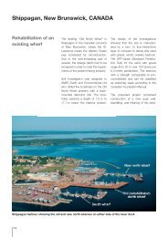
2.5 Industrial hall, Krimpen aan den Ijssel,<br />
Netherlands<br />
This production hall is 85 m in length, 40 m wide and 24 m high with full<br />
height doors at the end of the building, as shown in Figure 2.6. The roof<br />
structure consists of an inclined truss. Because of the lack of bracing in the end<br />
walls, the structure was designed to be stabilised through the columns assisted<br />
by in-plane bracing in the roof and side walls.<br />
Figure 2.6 View of doors being lifted into place in Hollandia’s building in<br />
Krimpen aan den Ijssel<br />
2 - 17
<strong>Part</strong> 2: Concept Design<br />
2.6 Distribution Centre and office, Barendrecht,<br />
Netherlands<br />
This 26000 m 2 distribution centre for a major supermarket in the Netherlands<br />
comprises a conventional steel structure for the distribution area and a two<br />
storey high office area that is suspended above an access road, as shown in<br />
Figure 2.7. This 42 m long office building comprises a 12 m cantilever<br />
supported by a two storey high internal steel structure with diagonal bracing.<br />
The structure uses H section beams and columns with tubular bracing.<br />
Both the warehouse and office buildings are provided with sprinklers to reduce<br />
the risk of fire, and the steelwork has intumescent coating so that it can be<br />
exposed internally. The warehouse internal temperature is 2°C and the<br />
steelwork of the office is thermally isolated from the warehouse part.<br />
Figure 2.7 Distribution centre, Barendrecht, NL showing the braced cantilever<br />
office structure<br />
2 - 18
<strong>Part</strong> 2: Concept Design<br />
3 CONCEPT DESIGN OF PORTAL FRAMES<br />
<strong>Steel</strong> portal frames are widely used because they combine structural efficiency<br />
with functional form. Various configurations of portal frame can be designed<br />
using the same structural concept as shown in Figure 3.1.<br />
1 2<br />
3<br />
5<br />
6<br />
1 Duo-pitch portal frame<br />
2 Curved portal frame (cellular beam)<br />
3 Portal with internal offices<br />
4 Portal with crane<br />
5 Two-span portal frame<br />
6 Portal with external offices<br />
Figure 3.1 Various types of portal frame<br />
2 - 19<br />
4
<strong>Part</strong> 2: Concept Design<br />
3.1 Pitched roof portal frame<br />
A single-span symmetrical portal frame (as illustrated in Figure 3.2) is<br />
typically of the following proportions:<br />
� A span between 15 m and 50 m (25 m to 35 m is the most efficient)<br />
� An eaves height (base to rafter centreline) of between 5 and 10 m (7,5 m is<br />
commonly adopted). The eaves height is determined by the specified clear<br />
height between the top of the floor and the underside of the haunch.<br />
� A roof pitch between 5� and 10� (6° is commonly adopted)<br />
� A frame spacing between 5 m and 8 m (the greater frame spacings being<br />
used in longer span portal frames)<br />
� Members are I sections rather than H sections, because they must carry<br />
significant bending moments and provide in-plane stiffness.<br />
� Sections are generally S235 or S275. Because deflections may be critical,<br />
the use of higher strength steel is rarely justified.<br />
� Haunches are provided in the rafters at the eaves to enhance the bending<br />
resistance of the rafter and to facilitate a bolted connection to the column.<br />
� Small haunches are provided at the apex, to facilitate the bolted connection<br />
1<br />
5<br />
2<br />
Figure 3.2 <strong>Single</strong>-span symmetric portal frame<br />
6<br />
2 - 20<br />
3<br />
4<br />
7<br />
1 Eaves<br />
2 Roof pitch<br />
3 Apex<br />
4 Rafter<br />
5 Eaves haunch<br />
6 Apex haunch<br />
7 Column<br />
The eaves haunch is typically cut from the same size rolled section as the<br />
rafter, or one slightly larger, and is welded to the underside of the rafter. The<br />
length of the eaves haunch is generally 10% of the span. The length of the<br />
haunch means that the hogging bending moment at the “sharp” end of the<br />
haunch is approximately the same as the maximum sagging bending moment<br />
towards the apex, as shown in Figure 3.3.
<strong>Part</strong> 2: Concept Design<br />
h<br />
h<br />
1 Moment at the “sharp” end of the haunch<br />
2 Maximum sagging moment<br />
3 Haunch length<br />
3<br />
Figure 3.3 Rafter bending moment and haunch length<br />
2 - 21<br />
1<br />
The final frames of a portal frame are generally called gable frames. Gable<br />
frames may be identical to the internal frames, even though they experience<br />
lighter loads. If future extension to the building is envisaged, portal frames are<br />
commonly used as the gable frames, to reduce the impact of the structural<br />
works. A typical gable frame is shown in Figure 3.4.<br />
2<br />
4<br />
1 Rafter<br />
2 Column<br />
3 Personnel door<br />
4 Roller shutter door<br />
5 Dado wall (brickwork)<br />
1<br />
Figure 3.4 Typical details of an end gable of a portal frame building<br />
3<br />
2<br />
5
<strong>Part</strong> 2: Concept Design<br />
Alternatively, gable frames can be constructed from columns and short rafters,<br />
simply supported between the columns as shown in Figure 3.5. In this case,<br />
gable bracing is required, as shown in the figure.<br />
Figure 3.5 Gable frame (not a portal frame)<br />
3.2 Frame stability<br />
In-plane stability is provided by frame continuity. In the longitudinal direction,<br />
stability is provided by vertical bracing in the elevations. The vertical bracing<br />
may be at both ends of the building, or in one bay only. Each frame is<br />
connected to the vertical bracing by a hot-rolled member at eaves level.<br />
A typical bracing arrangement is shown in Figure 3.6.<br />
2<br />
1 Vertical bracing in the gable<br />
2 Vertical bracing in the walls<br />
3 Roof bracing<br />
Figure 3.6 Typical bracing in a portal frame<br />
1<br />
The gable columns span between the base and the rafter, where the reaction is<br />
carried by bracing in the plane of the roof, back to the eaves level, and to the<br />
foundations by the vertical bracing.<br />
2 - 22<br />
3<br />
2
<strong>Part</strong> 2: Concept Design<br />
If diagonal bracing in the elevations cannot be accommodated, longitudinal<br />
stability can be provided by a rigid frame on the elevation, as shown in<br />
Figure 3.7.<br />
1 Eaves strut<br />
2 Rigid frame<br />
Figure 3.7 Rigid frame alternative to vertical bracing<br />
3.3 Member stability<br />
2 - 23<br />
2<br />
Member stability should be checked using expressions 6.61 and 6.62 of<br />
EN 1993-1-1. For economic design, restraints to the rafter and column must be<br />
considered. The purlins and side rails are considered adequate to restrain the<br />
flange that they are attached to, but unless special measures are taken, the<br />
purlins and side rails do not restrain the inside flange. Restraint to the inside<br />
flange is commonly provided by bracing from the purlins and side rails, as<br />
shown in Figure 3.8. The bracing is usually formed of thin metal straps,<br />
designed to act in tension, or from angles designed in compression if bracing is<br />
only possible from one side.<br />
If the bracing shown in Figure 3.8 is not permitted by national regulations,<br />
restraint may be provided by a system of hot-rolled members.<br />
This form of bracing will be required whenever the inside flange is in<br />
compression. This situation arises:<br />
� On the inside of the column and the inside of the rafter in the haunch<br />
region, in the gravity load combination<br />
� Towards the apex of the rafter, in the uplift combination.<br />
1
<strong>Part</strong> 2: Concept Design<br />
Figure 3.8 Typical bracing to the inside flange<br />
2 - 24<br />
2<br />
1<br />
1 Restraint to inside flange<br />
2 Purlin or side rail<br />
The arrangement of restraints to the inside flange is generally similar to that<br />
shown in Figure 3.9. In some instances, it may not be possible to restrain the<br />
inside of the column flange. In these circumstances, a larger column section<br />
may have to be chosen, which is stable between the underside of the haunch<br />
and the base.<br />
1<br />
1 Restraint to inside flange of rafter and column<br />
Figure 3.9 General arrangement of restraints to the inside flange<br />
In all cases, the junction of the inside face of the column and the underside of<br />
the haunch, as shown in Figure 3.10, must be restrained. The restraint may be<br />
of the form shown in Figure 3.8, or may be by a hot-rolled member provided<br />
for that purpose.<br />
1 Restraint position<br />
1<br />
Figure 3.10 Restraint at the haunch / column junction<br />
1
<strong>Part</strong> 2: Concept Design<br />
3.4 Preliminary Design<br />
3.4.1 Main frames<br />
Although efficient portal frame analysis and design will use bespoke software,<br />
preliminary design is simple. In most circumstances, a reasonable estimate of<br />
the maximum bending moments will be obtained by considering only the<br />
vertical loads. Combinations of actions including wind actions must be<br />
validated in the final design, and may be important for preliminary design if the<br />
wind actions are onerous (e.g. near the sea, or if the portal frame is tall).<br />
Based on the vertical load alone, charts that provide initial sizes are given in<br />
Section 8.<br />
As an alternative to the sizes given in Section 8, the bending moment at the<br />
eaves and apex can be calculated based on an elastic analysis.<br />
ME<br />
IR<br />
I C<br />
WL<br />
32<br />
2<br />
2 - 25<br />
W / m<br />
L<br />
MA<br />
Figure 3.11 Details of a pinned base portal frame<br />
For the pinned base frame shown in Figure 3.11, the bending moment at the<br />
eaves, ME and at the apex MA can be calculated as follows:<br />
�3�5m� 2<br />
wL<br />
M E �<br />
16N<br />
where:<br />
N = B + mC<br />
C = 1 + 2m<br />
and M A<br />
2<br />
wL<br />
� � m�<br />
M E<br />
8<br />
B = 2(k + 1) + m<br />
m = 1 + �<br />
� =<br />
f<br />
h<br />
I<br />
k �<br />
I<br />
R<br />
C<br />
h<br />
s<br />
S<br />
IR<br />
IC<br />
f<br />
h
<strong>Part</strong> 2: Concept Design<br />
It may be assumed for preliminary design that IC = 1,5 � IR<br />
Given the bending moments around the frame, the rafter should be chosen so<br />
that the moment resistance exceeds both the moment at the “sharp” end of the<br />
haunch and the maximum sagging moment (a little larger than the moment at<br />
the apex).<br />
3.4.2 Gable columns<br />
Gable columns are generally designed as simply supported from base to rafter.<br />
The primary loads are the wind actions. The internal pressure or suction will<br />
contribute to the loading on the gable column. Often, the critical design case<br />
will be pressure inside the building and suction on the outside, when the inside<br />
flange of the gable post is unrestrained. If national regulations allow, a restraint<br />
to the inside flange may be provided from a sheeting rail to increase the<br />
buckling resistance.<br />
3.4.3 Bracing<br />
At the preliminary design stage, it is convenient to calculate the overall<br />
longitudinal load on the structure. This shear must be the horizontal component<br />
of the load carried by the vertical bracing. The most heavily loaded roof<br />
bracing will be the member nearest the eaves. The longitudinal eaves member<br />
carries the load from the roof bracing to the vertical bracing. Bracing members<br />
may be hollow sections, angle sections or flat steel. Flat steel is assumed to<br />
resist tension forces only.<br />
2 - 26
<strong>Part</strong> 2: Concept Design<br />
3.5 Connections<br />
3.5.1 Eaves connection<br />
A typical eaves connection is shown in Figure 3.12. In almost all cases a<br />
compression stiffener in the column (as shown, at the bottom of the haunch)<br />
will be required. Other stiffeners may be required to increase the bending<br />
resistance of the column flange, adjacent to the tension bolts, and to increase<br />
the shear resistance of the column web panel. The haunch is generally<br />
fabricated from a similar size beam to the rafter (or larger), or fabricated from<br />
equivalent plate. Typically, the bolts may be M24 8.8 and the end plate 25 mm<br />
thick S275.<br />
1 Haunch<br />
2 Compression stiffener<br />
Figure 3.12 Typical eaves connection<br />
2 - 27<br />
2<br />
3.5.2 Apex connection<br />
A typical apex connection is shown in Figure 3.13. The apex connection<br />
primarily serves to increase the depth of the member to make a satisfactory<br />
bolted connection. The apex haunch is usually fabricated from the same<br />
member as the rafter, or from equivalent plate. Typically, the bolts may be<br />
M24 8.8 and the end plate 25 mm thick S275.<br />
Figure 3.13 Typical apex connection<br />
1
<strong>Part</strong> 2: Concept Design<br />
3.5.3 Bases<br />
A typical pinned base is shown in Figure 3.14. The base plate is generally at<br />
least as thick as the flange of the column. Most authorities accept that even<br />
with four holding down bolts as shown in Figure 3.14, the base is still pinned.<br />
Alternatively, the base may have only two holding down bolts, on the axis of<br />
the column, but this may make the erection of the steelwork more difficult.<br />
Columns are normally located on a number of steel packs, to ensure the<br />
steelwork is at the correct level, and the gap between the foundation and the<br />
steelwork filled with cementicious grout. Large bases should be provided with<br />
an air hole to facilitate complete grouting.<br />
Holding down bolts are generally embedded in the foundation, with some<br />
freedom of lateral movement (tubes or cones) so that the steelwork can be<br />
aligned precisely. The holes in the base plate are usually 6 mm larger than the<br />
bolt diameter, to facilitate some lateral alignment.<br />
4<br />
Figure 3.14 Typical portal base detail<br />
1<br />
2 - 28<br />
5<br />
2<br />
3<br />
~<br />
1 Holding down bolts<br />
2 Base plate<br />
3 Grout<br />
4 Tube (or cone)<br />
5 Anchor plate<br />
3.5.4 Bracing Connections<br />
Forces in portal frame bracing are generally modest. Typical connections are<br />
shown in Figure 3.15. Gusset plates should be supported on two edges, if<br />
possible.
<strong>Part</strong> 2: Concept Design<br />
Figure 3.15 Typical bracing connections<br />
3.6 Other types of portal frame<br />
The features of an orthodox portal frame were described in Sections 3.1 to 3.5.<br />
The basic structural concept can be modified in a number of ways to produce a<br />
cost effective solution, as illustrated below.<br />
3.6.1 Portal frame with a mezzanine floor<br />
1 Mezzanine<br />
1<br />
Figure 3.16 Portal frame with internal mezzanine floor<br />
Office accommodation is often provided within a portal frame structure using a<br />
mezzanine floor (as illustrated in Figure 3.17). The mezzanine floor may be<br />
partial or full width. It can be designed to stabilise the frame. Often, the<br />
internal floor of the office space requires fire protection.<br />
2 - 29
<strong>Part</strong> 2: Concept Design<br />
Figure 3.17 Portal frame with intermediate floor<br />
3.6.2 Portal frame with external mezzanine<br />
1<br />
1 Mezzanine<br />
Figure 3.18 Portal frame with external mezzanine<br />
Offices may be located externally to the portal frame which creates an<br />
asymmetric portal structure (as illustrated in Figure 3.18). The main advantage<br />
of this framework is that large columns and haunches do not obstruct the office<br />
space. Generally, this additional structure depends on the portal frame for its<br />
stability (the members often have nominally pinned connections to the main<br />
frame) and the members can be relatively lightweight.<br />
2 - 30
<strong>Part</strong> 2: Concept Design<br />
3.6.3 Portal frame with overhead crane<br />
Figure 3.19 Crane portal frame with column brackets<br />
For cranes of relatively low capacity (up to say 20 tonnes), portal frames can<br />
be used to support the crane beam and rail, as illustrated in Figure 3.19. The<br />
outward movement (spread) of the frame at the level of the crane rail is likely<br />
to be of critical importance. Use of a horizontal tie member or fixed column<br />
bases may be necessary to reduce this spread.<br />
For larger cranes, a structure with a roof truss will be appropriate (see<br />
Section 4) as the column spread is minimised. For very heavy loads, built-up<br />
columns are appropriate, as introduced in Section 6. Detail design guides cover<br />
both the design of trusses [3] and the design of built-up columns [4] .<br />
3.6.4 Tied portal frame<br />
1 Tie<br />
2 Hangers (required for longer spans)<br />
Figure 3.20 Tied portal frame<br />
2 - 31<br />
1<br />
In a tied portal frame, as illustrated in Figure 3.20, the spread of the eaves and<br />
the bending moments in the frame are greatly reduced. Large compression<br />
forces will develop in the rafters, which reduce the stability of the members.<br />
Second-order software must be used for the design of tied portals.<br />
2
<strong>Part</strong> 2: Concept Design<br />
3.6.5 Mansard or curved portal frames<br />
Figure 3.21 Mansard portal frame<br />
A mansard portal frame consists of a series of rafters and haunches, as<br />
illustrated in Figure 3.21, which creates a pseudo-curved frame. The<br />
connections between the members may also have small haunches to facilitate<br />
the bolted connections.<br />
Curved rafter portals as illustrated in Figure 3.22 are often used for<br />
architectural applications. The rafter can be curved to a radius by cold bending.<br />
For spans greater than approximately 18 m, splices may be required in the<br />
rafter because of limitations of transport.<br />
Alternatively, a curved external roof must be produced by varying the lengths<br />
of purlin brackets supported on a rafter fabricated as a series of straight<br />
elements, as shown in Figure 3.23.<br />
Figure 3.22 Curved beams used in a portal frame<br />
2 - 32
<strong>Part</strong> 2: Concept Design<br />
Figure 3.23 Quasi- curved portal frame<br />
3.6.6 Multi bay portal frame<br />
Multi-bay portal frames may be designed by using intermediate columns, as<br />
shown in Figure 3.24. If the number of internal columns must be minimised it<br />
is possible to remove every second internal column, or to only leave one<br />
internal column every third frame. Where the internal column is removed, a<br />
deep beam (often known as a “valley” beam) is designed to span between the<br />
remaining columns. Continuity of the rafters is achieved by using a haunch<br />
connection to the valley beam, as shown in Figure 3.25.<br />
Figure 3.24 Multi-bay portal frame<br />
2 - 33
<strong>Part</strong> 2: Concept Design<br />
1 Valley beam<br />
2 Rafter<br />
2<br />
Figure 3.25 Connection to valley beam<br />
2 - 34<br />
1
<strong>Part</strong> 2: Concept Design<br />
4 CONCEPT DESIGN OF TRUSS <strong>BUILD<strong>IN</strong>GS</strong><br />
4.1 Introduction<br />
Many forms of truss are possible. Some of the common types of truss for single<br />
storey buildings are shown in Figure 4.1.<br />
Trusses are used for long spans, and particularly when significant loads must<br />
be carried by the roof structure, as the vertical deflection can be controlled by<br />
varying the member sizes.<br />
For industrial buildings, the W-truss N-truss and duo-pitch truss are common.<br />
The Fink truss is generally used for smaller spans. Comparing the W-truss and<br />
N-truss:<br />
� The W-truss has more open space between the internal members<br />
� The internal members of the W-truss may be larger, because a long<br />
diagonal member must carry compression – the compression members in<br />
the N-truss are short.<br />
1 2<br />
3 4<br />
5<br />
1 W-truss<br />
2 N-truss<br />
3 Duo-pitch truss<br />
4 Fink truss<br />
5 Curved truss<br />
Figure 4.1 Various forms of lattice truss used in industrial buildings<br />
2 - 35
<strong>Part</strong> 2: Concept Design<br />
4.2 Truss members<br />
Unless there are special architectural requirements, truss members are chosen<br />
to produce a simple connection between the chords and the internal members.<br />
Common combinations as shown in Figure 4.2 are:<br />
� Tees used as chords, with angles used as web members. The angles may be<br />
welded or bolted to the stem of the Tee.<br />
� Double angle members as chords, and single (or double) angles as internal<br />
members. The connections are made with a gusset plate welded between<br />
the angles forming the chords.<br />
� Rolled sections as chords, with the web in the plane of the truss. The<br />
internal members are usually angle members, connected via a gusset plate<br />
welded to the chord.<br />
� Rolled sections as chords, but with the web perpendicular to the plane of<br />
the truss. The connections to the chord members may be via gusset plates<br />
welded to the web, although the connections will need careful detailing.<br />
A simple, effective alternative is to choose chords that have the same<br />
overall depth, and connect the internal members to the outside of both<br />
flanges, generally by welding.<br />
� For heavily loaded trusses, rolled I or H sections, or channel sections may<br />
be used as the internal members. In such a large truss, developing economic<br />
connections will be important and both the members and internal members<br />
should be chosen with this in mind.<br />
The detailed design of trusses is covered in <strong>Single</strong>-storey steel buildings.<br />
<strong>Part</strong>5: Detailed design of trusses [3] .<br />
2 - 36
<strong>Part</strong> 2: Concept Design<br />
3<br />
3<br />
2<br />
1 Tee section<br />
2 Angle members<br />
3 Gusset plate<br />
4 Double angle chord<br />
Figure 4.2 Typical truss members<br />
2 - 37<br />
1<br />
A truss fabricated from rolled sections is illustrated in Figure 4.3.<br />
3<br />
4
<strong>Part</strong> 2: Concept Design<br />
Figure 4.3 Truss fabricated from rolled sections<br />
4.3 Frame stability<br />
In most cases, frame stability is provided by bracing in both orthogonal<br />
directions, and the truss is simply pinned to the supporting columns. To realise<br />
a pinned connection, one of the chord members is redundant, as shown in<br />
Figure 4.4, and the connection of that redundant member to the column is<br />
usually allowed to slip in the direction of the axis of the chord.<br />
1<br />
1 Redundant member<br />
Figure 4.4 Redundant member in a simply supported truss<br />
In the longitudinal direction, stability is usually provided by vertical bracing.<br />
2 - 38
<strong>Part</strong> 2: Concept Design<br />
4.4 Preliminary design<br />
At the preliminary design stage, the following process is recommended:<br />
1. Determine the loading on the truss. See Section 1.4.1. At the preliminary<br />
design stage it is sufficient to convert all loads, including self weight, to<br />
point loads applied at the nodes and assume that the entire truss is<br />
pin-jointed. This assumption is also generally adequate for final design. As<br />
an alternative, the roof loads may be applied at the purlin positions and the<br />
chords assumed to be continuous over pinned internal members, but the<br />
precision is rarely justified.<br />
2. Determine a truss depth and layout of internal members. A typical<br />
span : depth ratio is approximately 20 for both W- and N-trusses. Internal<br />
members are most efficient between 40° and 50°.<br />
3. Determine the forces in the chords and internal members, assuming the<br />
truss is pin-jointed throughout. This can be done using software, or by<br />
simple manual methods of resolving forces at joints or by taking moments<br />
about a pin, as shown in Figure 4.5.<br />
VL<br />
VL<br />
p<br />
VL<br />
x<br />
d<br />
p<br />
p<br />
VL<br />
x<br />
d<br />
Resolving forces at joints<br />
V L<br />
p<br />
1<br />
C<br />
A B C<br />
Taking moments around node D determines the force CB<br />
Figure 4.5 Calculation of forces in a pin-jointed truss<br />
2 - 39<br />
D<br />
A very simple approach is to calculate the maximum bending moment in<br />
the truss assuming that it behaves as a beam, and divide this moment by the<br />
distance between chords to determine the axial force in the chord.<br />
4. Select the compression chord member. The buckling resistance is based on<br />
the length between node points for in-plane buckling. The out-of-plane<br />
d
<strong>Part</strong> 2: Concept Design<br />
buckling is based on the length between out-of-plane restraints – usually the<br />
roof purlins or other members.<br />
5. Select the tension chord member. The critical design case is likely to be an<br />
uplift case, when the lower chord is in compression. The out-of-plane<br />
buckling is likely to be critical. It is common to provide a dedicated system<br />
of bracing at the level of the bottom chord, to provide restraint in the<br />
reversal load combination. This additional bracing is not provided at every<br />
node of the truss, but as required to balance the tension resistance with the<br />
compression resistance.<br />
6. Choose internal members, whilst ensuring the connections are not<br />
complicated.<br />
7. Check truss deflections.<br />
4.5 Rigid frame trusses<br />
The structures described in Sections 4.1 and 4.4 are stabilised by bracing in<br />
each orthogonal direction. It is possible to stabilise the frames in-plane, by<br />
making the truss continuous with the columns. Both chords are fixed to the<br />
columns (i.e. no slip connection). The connections within the truss and to the<br />
columns may be pinned. The frame becomes similar to a portal frame. For this<br />
form of frame, the analysis is generally completed using software. <strong>Part</strong>icular<br />
attention must be paid to column design, because the in-plane buckling length<br />
is usually much larger than the physical length of the member.<br />
4.6 Connections<br />
Truss connections are either bolted or welded to the chord members, either<br />
directly to the chord, or via gusset plates, as shown in Figure 4.6.<br />
3<br />
Figure 4.6 Truss connections<br />
Trusses will generally be prefabricated in the workshop, and splices maybe<br />
required on site. In addition to splices in the chords, the internal member at the<br />
splice position will also require a site connection. Splices may be detailed with<br />
cover plates, or as “end plate” type connections, as shown in Figure 4.7.<br />
2 - 40
<strong>Part</strong> 2: Concept Design<br />
Figure 4.7 Splice details<br />
Ordinary bolts (non-preloaded) in clearance holes may give rise to some slip in<br />
the connection. If this slip is accumulated over a large number of connections,<br />
the defection of the truss may be larger than calculated. If deflection is a<br />
critical consideration, then friction grip assemblies or welded details should be<br />
used.<br />
2 - 41
<strong>Part</strong> 2: Concept Design<br />
5 SIMPLE BEAM STRUCTURES<br />
For modest spans, (up to approximately 20 m) a simple beam and column<br />
structure can be provided, as illustrated in Figure 5.1. The roof beam is a<br />
single rolled section, with nominally pinned connections to the columns. The<br />
roof beam may be straight, precambered, perforated or curved. The roof may<br />
be horizontal, or more commonly with a modest slope to assist drainage.<br />
Ponding of water on the roof should be avoided with a slope, or precambered<br />
beam.<br />
Figure 5.1 Simple beam and column frame<br />
Frame stability for this form of structure is provided by bracing in each<br />
orthogonal direction. The beam is designed as simply supported, and the<br />
columns as simple struts, with a nominal moment applied by the beam<br />
connection. It is common to assume that the shear force from the beam is<br />
applied 100 mm from the face of the column.<br />
2 - 42
<strong>Part</strong> 2: Concept Design<br />
6 BUILT-UP COLUMNS<br />
Heavily loaded columns, or columns in tall industrial buildings may be in the<br />
form of built-up sections. Built-up columns often comprise HE or UPE sections<br />
in which battens (flat plate) or lacing (usually angles) are welded across the<br />
flanges, as shown in Figure 6.1.<br />
Built-up columns are not used in portal frames, but are often used in buildings<br />
supporting heavy cranes. The roof of the structure may be duo-pitch rafters, but<br />
is more commonly a truss, as illustrated in Figure 1.4.<br />
Figure 6.1 Cross-sections of built-up columns<br />
To support the roof above the level of the crane, a single member may project<br />
for several meters. This is often known as a “bayonet” column. The projecting<br />
member may be a continuation of one of the two primary sections in the<br />
built-up section, or may be a separate section located centrally to the built-up<br />
section. Examples of built-up columns are shown in Figure 6.2. <strong>Buildings</strong> that<br />
use built-up columns are invariably heavily loaded, and commonly subjected to<br />
moving loads from cranes. Such buildings are heavily braced in two orthogonal<br />
directions.<br />
The detailed design of built-up columns is covered in <strong>Single</strong>-storey steel<br />
buildings. <strong>Part</strong> 6: Detailed design of built-up columns [4] of this guide.<br />
2 - 43
<strong>Part</strong> 2: Concept Design<br />
Laced column Battened column Column with<br />
crane girder<br />
Figure 6.2 Examples of built-up columns in single storey buildings<br />
2 - 44
<strong>Part</strong> 2: Concept Design<br />
7 CLADD<strong>IN</strong>G<br />
There are a number of generic types of cladding that may be used in single<br />
storey buildings, depending on the building use. These fall into four broad<br />
categories, which are described in the following sections.<br />
7.1 <strong>Single</strong>-skin trapezoidal sheeting<br />
<strong>Single</strong>-skin sheeting is widely used in agricultural and industrial structures<br />
where no insulation is required. It can generally be used on roof slopes as low<br />
as 4° providing the laps and sealants are as recommended by the manufacturers<br />
for shallow slopes. The sheeting is fixed directly to the purlins and side rails, as<br />
illustrated in Figure 7.1 and provides positive restraint. In some cases,<br />
insulation is suspended directly beneath the sheeting.<br />
Figure 7.1 <strong>Single</strong>-skin trapezoidal sheeting<br />
7.2 Double-skin system<br />
Double skin or built-up roof systems usually use a steel liner tray that is<br />
fastened to the purlins, followed by a spacing system (plastic ferrule and spacer<br />
or rail and bracket spacer), insulation and the outer profiled sheeting. Because<br />
the connection between the outer and inner sheets may not be sufficiently stiff,<br />
the liner tray and fixings must be chosen so that they alone will provide the<br />
required level of restraint to the purlins. This form of construction using plastic<br />
ferrules is shown in Figure 7.2.<br />
As insulation depths have increased, there has been a move towards “rail and<br />
bracket” solutions as they provide greater lateral restraint to the purlins. This<br />
system is illustrated in Figure 7.3.<br />
With adequate sealing of joints, the liner trays may be used to form an airtight<br />
boundary. Alternatively, an impermeable membrane on top of the liner tray<br />
should be provided.<br />
2 - 45
<strong>Part</strong> 2: Concept Design<br />
2<br />
1 Outer sheeting<br />
2 Z spacer<br />
3 Insulation<br />
4 Liner tray (inner sheet)<br />
5 Plastic ferrule<br />
Figure 7.2 Double-skin construction using plastic ferrule and Z spacers<br />
3<br />
1 Outer sheet<br />
2 Insulation<br />
3 Rail<br />
4 Liner tray (inner sheet)<br />
5 Bracket<br />
4<br />
Figure 7.3 Double-skin construction using ‘rail and bracket’ spacers<br />
2 - 46<br />
5<br />
1<br />
4<br />
1<br />
5<br />
3<br />
2
<strong>Part</strong> 2: Concept Design<br />
7.3 Standing seam sheeting<br />
Standing seam sheeting has concealed fixings and can be fixed in lengths of up<br />
to 30 m. The advantages are that there are no penetrations directly through the<br />
sheeting that could lead to water leakage and fixing of the roof sheeting is<br />
rapid. The fastenings are in the form of clips that hold the sheeting down but<br />
allow it to move longitudinally (see Figure 7.4). The disadvantage of this<br />
system is that less restraint is provided to the purlins than with a conventionally<br />
fixed system. Nevertheless, a correctly fixed liner tray should provide adequate<br />
restraint.<br />
3<br />
1 Outer sheet<br />
2 Insulation<br />
3 Standing seam clip<br />
Figure 7.4 Standing seam panels with liner trays<br />
7.4 Composite or sandwich panels<br />
Composite or sandwich panels are formed by creating a foam insulation layer<br />
between the outer and inner layer of sheeting. Composite panels have good<br />
spanning capabilities due to composite action of the core with the steel sheets.<br />
Both standing seam (see Figure 7.4) and direct fixing systems are available.<br />
These will clearly provide widely differing levels of restraint to the purlins.<br />
The manufacturers should be consulted for more information.<br />
7.5 Fire design of walls<br />
Where buildings are close to a site boundary, most national Building<br />
Regulations require that the wall is designed to prevent spread of fire to<br />
adjacent property. Fire tests have shown that a number of types of panel can<br />
perform adequately, provided that they remain fixed to the structure. Further<br />
guidance should be sought from the manufacturers.<br />
2 - 47<br />
1<br />
2
<strong>Part</strong> 2: Concept Design<br />
Some manufacturers provide slotted holes in the side rail connections to allow<br />
for thermal expansion. In order to ensure that this does not compromise the<br />
stability of the column by removing the restraint under normal conditions, the<br />
slotted holes are fitted with washers made from a material that will melt at high<br />
temperatures and allow the side rail to move relative to the column under fire<br />
conditions only. Details of this type of system are illustrated in Figure 7.5.<br />
2<br />
1 Side rail<br />
2 Slotted hole for expansion<br />
3 Cleat<br />
3<br />
1<br />
Figure 7.5 Typical fire wall details showing slotted holes for expansion in fire<br />
2 - 48
<strong>Part</strong> 2: Concept Design<br />
8 PRELIM<strong>IN</strong>ARY DESIGN OF PORTAL<br />
FRAMES<br />
8.1 Introduction<br />
The following methods of determining the size of columns and rafters of<br />
single-span portal frames may be used at the preliminary design stage. Further<br />
detailed calculations will be required at the final design stage. It should be<br />
noted that the method does not take account of:<br />
� Requirements for overall stability<br />
� Deflections at the Serviceability Limit State.<br />
8.2 Estimation of member sizes<br />
The guidance for portal frames is valid in the span range between 15 to 40 m.<br />
and is presented in Table 8.1. The assumptions made in creating this table are<br />
as follows:<br />
� The roof pitch is 6�.<br />
� The steel grade is S235. If design is controlled by serviceability conditions,<br />
the use of smaller sections in higher grades may not be an advantage. When<br />
deflections are not a concern, for example when the structure is completely<br />
clad in metal cladding, the use of higher grades may be appropriate.<br />
� The rafter load is the total factored permanent actions (including self<br />
weight) and factored variable actions and is in the range of 8 to 16 kN/m.<br />
� Frames are spaced at 5 to 7,5 m.<br />
� The haunch length is 10% of the span of the frame.<br />
� A column is treated as restrained when torsional restraints can be provided<br />
along its length (these columns are therefore lighter than the equivalent<br />
unrestrained columns).<br />
� A column should be considered as unrestrained when it is not possible to<br />
restrain the inside flange.<br />
The member sizes given by the tables are suitable for rapid preliminary design.<br />
However, where strict deflection limits are specified, it may be necessary to<br />
increase the member sizes.<br />
In all cases, a full design must be undertaken and members verified in<br />
accordance with EN 1993-1-1.<br />
2 - 49
2 - 50<br />
Table 8.1 Member sizes for single-span portal frame with 6° roof pitch<br />
Rafter load<br />
(kN/m)<br />
Rafter 8<br />
8<br />
8<br />
Restrained<br />
column<br />
Unrestrained<br />
column<br />
8<br />
8<br />
8<br />
8<br />
8<br />
8<br />
Rafter 10<br />
10<br />
10<br />
Restrained<br />
column<br />
Unrestrained<br />
column<br />
10<br />
10<br />
10<br />
10<br />
10<br />
10<br />
Rafter 12<br />
12<br />
12<br />
Restrained<br />
column<br />
Unrestrained<br />
column<br />
12<br />
12<br />
12<br />
12<br />
12<br />
12<br />
Eaves height<br />
(m)<br />
6<br />
8<br />
10<br />
6<br />
8<br />
10<br />
6<br />
8<br />
10<br />
6<br />
8<br />
10<br />
6<br />
8<br />
10<br />
6<br />
8<br />
10<br />
6<br />
8<br />
10<br />
6<br />
8<br />
10<br />
6<br />
8<br />
10<br />
Span of frame (m)<br />
15 20 25 30 35 40<br />
IPE 240<br />
IPE 240<br />
IPE 240<br />
IPE 300<br />
IPE 300<br />
IPE 300<br />
IPE 360<br />
IPE 450<br />
IPE 450<br />
IPE 270<br />
IPE 270<br />
IPE 270<br />
IPE 360<br />
IPE 360<br />
IPE 360<br />
IPE 400<br />
IPE 450<br />
IPE 450<br />
IPE 270<br />
IPE 270<br />
IPE 270<br />
IPE 360<br />
IPE 360<br />
IPE 360<br />
IPE 450<br />
IPE 450<br />
IPE 550<br />
IPE 330<br />
IPE 330<br />
IPE 330<br />
IPE 360<br />
IPE 360<br />
IPE 400<br />
IPE 450<br />
IPE 550<br />
IPE 550<br />
IPE 330<br />
IPE 330<br />
IPE 360<br />
IPE 450<br />
IPE 450<br />
IPE 450<br />
IPE 450<br />
IPE 550<br />
IPE 600<br />
IPE 360<br />
IPE 360<br />
IPE 60<br />
IPE 450<br />
IPE 450<br />
IPE 450<br />
IPE 550<br />
IPE 600<br />
IPE 600<br />
IPE 360<br />
IPE 360<br />
IPE 360<br />
IPE 450<br />
IPE 450<br />
IPE 450<br />
IPE 550<br />
IPE 600<br />
IPE 600<br />
IPE 400<br />
IPE 400<br />
IPE 400<br />
IPE 450<br />
IPE 550<br />
IPE 550<br />
IPE 550<br />
IPE 600<br />
IPE 750 � 137<br />
IPE 400<br />
IPE 400<br />
IPE 400<br />
IPE 550<br />
IPE 550<br />
IPE 550<br />
IPE 600<br />
IPE 600<br />
IPE 750 � 173<br />
IPE 400<br />
IPE 400<br />
IPE 400<br />
IPE 550<br />
IPE 550<br />
IPE 550<br />
IPE 550<br />
IPE 600<br />
IPE 750 � 137<br />
IPE 450<br />
IPE 450<br />
IPE 450<br />
IPE 550<br />
IPE 550<br />
IPE 600<br />
IPE 600<br />
IPE 750 � 137<br />
IPE 750 � 173<br />
IPE 450<br />
IPE 450<br />
IPE 450<br />
IPE 600<br />
IPE 600<br />
IPE 600<br />
IPE 600<br />
IPE 750 � 173<br />
HE 800<br />
IPE 450<br />
IPE 450<br />
IPE 450<br />
IPE 550<br />
IPE 600<br />
IPE 600<br />
IPE 0 600<br />
IPE 750 � 137<br />
IPE 750 � 173<br />
IPE 0 450<br />
IPE 0 450<br />
IPE 0 450<br />
IPE 600<br />
IPE 600<br />
IPE 600<br />
IPE 750 � 137<br />
IPE 750 � 173<br />
HE 800<br />
IPE 550<br />
IPE 550<br />
IPE 550<br />
IPE 750 � 137<br />
IPE 750 � 137<br />
IPE 750 � 137<br />
IPE 750 � 137<br />
HE 800<br />
HE 800<br />
IPE 450<br />
IPE 450<br />
IPE 450<br />
IPE 600<br />
IPE 600<br />
IPE 750 � 137<br />
IPE 750 � 137<br />
IPE 750 � 173<br />
HE 800<br />
IPE 550<br />
IPE 550<br />
IPE 550<br />
IPE 750 � 137<br />
IPE 750 � 137<br />
IPE 750 � 173<br />
IPE 750 � 137<br />
HE 800<br />
HE 800<br />
IPE 550<br />
IPE 550<br />
IPE 600<br />
IPE 750 � 173<br />
IPE 750 � 173<br />
IPE 750 � 173<br />
IPE 750 � 173<br />
HE 800<br />
HE 900<br />
<strong>Part</strong> 2: Concept Design
2 - 51<br />
Table 8.1 (Continued) <strong>Single</strong>-span portal frame with 6° roof pitch<br />
Rafter load<br />
(kN/m)<br />
Rafter 14<br />
14<br />
14<br />
Restrained<br />
column<br />
Unrestrained<br />
column<br />
14<br />
14<br />
14<br />
14<br />
14<br />
14<br />
Rafter 16<br />
16<br />
16<br />
Restrained<br />
column<br />
Unrestrained<br />
column<br />
16<br />
16<br />
16<br />
16<br />
16<br />
16<br />
Eaves height<br />
(m)<br />
6<br />
8<br />
10<br />
6<br />
8<br />
10<br />
6<br />
8<br />
10<br />
6<br />
8<br />
10<br />
6<br />
8<br />
10<br />
6<br />
8<br />
10<br />
Span of frame (m)<br />
15 20 25 30 35 40<br />
IPE 330<br />
IPE 330<br />
IPE 330<br />
IPE 360<br />
IPE 400<br />
IPE 400<br />
IPE 450<br />
IPE 550<br />
IPE 550<br />
IPE 330<br />
IPE 330<br />
IPE 330<br />
IPE 400<br />
IPE 400<br />
IPE 450<br />
IPE 450<br />
IPE 550<br />
IPE 600<br />
IPE 400<br />
IPE 400<br />
IPE 400<br />
IPE 450<br />
IPE 450<br />
IPE 450<br />
IPE 550<br />
IPE 600<br />
IPE 750 � 137<br />
IPE 400<br />
IPE 400<br />
IPE 400<br />
IPE 550<br />
IPE 550<br />
IPE 550<br />
IPE 550<br />
IPE 600<br />
IPE 750 � 137<br />
IPE 450<br />
IPE 450<br />
IPE 450<br />
IPE 550<br />
IPE 550<br />
IPE 600<br />
IPE 600<br />
IPE 750 � 137<br />
IPE 750 � 173<br />
IPE 450<br />
IPE 450<br />
IPE 450<br />
IPE 600<br />
IPE 600<br />
IPE 600<br />
IPE 600<br />
IPE 750 � 173<br />
HE 800<br />
IPE 450<br />
IPE 450<br />
IPE 450<br />
IPE 600<br />
IPE 600<br />
IPE 750 � 137<br />
IPE 750 � 137<br />
IPE 750 � 173<br />
HE 800<br />
IPE 550<br />
IPE 550<br />
IPE 50<br />
IPE 750 � 137<br />
IPE 750 � 137<br />
IPE 750 � 137<br />
IPE 750 � 137<br />
HE 800<br />
HE 800<br />
IPE 550<br />
IPE 550<br />
IPE 550<br />
IPE 750 � 173<br />
IPE 750 � 173<br />
IPE 750 � 173<br />
IPE 750 � 173<br />
HE 800<br />
HE 800<br />
IPE 550<br />
IPE 600<br />
IPE 600<br />
IPE 750 � 173<br />
IPE 750 � 173<br />
HE 800<br />
IPE 750 � 173<br />
HE 800<br />
HE 900<br />
IPE 600<br />
IPE 600<br />
IPE 600<br />
IPE 750 � 173<br />
HE 800<br />
HE 800<br />
HE 800<br />
HE 800<br />
HE 900<br />
IPE 600<br />
IPE 600<br />
IPE 600<br />
HE 800<br />
HE 800<br />
HE 800<br />
HE 800<br />
HE 900<br />
HE 900<br />
<strong>Part</strong> 2: Concept Design
<strong>Part</strong> 2: Concept Design<br />
REFERENCES<br />
1 SANSOM, M. and MEIJER, J.<br />
Life-cycle assessment (LCA) for steel construction<br />
European commission, 2002<br />
2 Several assessement methods are used. For example:<br />
� BREEAM in the UK<br />
� HQE in France<br />
� DNGB in Germany<br />
� BREEAM-NL, Greencalc+ and BPR Gebouw in the Netherlands<br />
� Valideo in Belgium<br />
� Casa Clima in Trento Alto Adige, Italy (each region has its own approach)<br />
� LEED, used in various countries<br />
3 <strong>Steel</strong> <strong>Buildings</strong> in Europe<br />
<strong>Single</strong>-storey steel buildings. <strong>Part</strong> 5: Design of trusses<br />
4 <strong>Steel</strong> <strong>Buildings</strong> in Europe<br />
<strong>Single</strong>-storey steel buildings. <strong>Part</strong> 6: Design of built-up columns<br />
2 - 52