Brochure - Precicon D&C Pte Ltd
Brochure - Precicon D&C Pte Ltd
Brochure - Precicon D&C Pte Ltd
- No tags were found...

You also want an ePaper? Increase the reach of your titles
YUMPU automatically turns print PDFs into web optimized ePapers that Google loves.
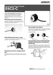
New ProductDigital TimerH5CX-@-NUltra-compact Timer Provides AdvancedFunctions and Security Settings.Basic Features• Short body with depth of only 59 mm (for 24-VAC / 12 to 24-VDC Models withScrew Terminals). *1• Character height of 12 mm for better readability (on models with 4 digits).• The present value display characters can be switched between red, green,and orange. *2Safety and Reliability• Power supply circuit and input circuits are isolated for safety and reliability. *3• New set value limit and output counter functions have been added.Other Features• Front Panel can be changed to white or light gray. *4• Models with instantaneous contact output added to the series.*1. For 100 to 240 VAC Models with Screw Terminals 78 mm, Models with Sockets: 63.7 mm(case dimension).*2. The H5CX-A11, H5CX-L8 and H5CX-B Timers have only red characters.*3. Specifications: 100 to 240 VAC*4. Replacement Front Panels sold separately.FeaturesBasic FeaturesUltra Short BodyThe body depth has been greatly reduced. Helps in making thinnercontrol panels. (Models with Screw Terminals)24-VAC / 12 to 24-VDC Models with Screw Terminals: 59 mm100 to 240-VAC / VDC Models with Screw Terminals: 78 mm *Models with Sockets: 63.7 mm (case dimension)* The shortest body for a timer with isolated power supply and input circuits and a maximumambient temperature of 55°C (according to OMRON investigation in June 2009).Safety and ReliabilityIsolated Power Supply and Input Circuits *1Power supply circuit and input circuits are isolated for safety andreliability.Previous non-isolated timers had wiring restrictions and could be damaged ifwired incorrectly. The New H5CX removes these worries.AC powersupply *2PreviousH5CXInput terminal0-V terminalRefer to “Safety Precautions” on page 41.Output terminal on PLCor other deviceCOM terminal–V +VForget TheseWorries with theNew H5CXEasier to ReadFor better readability, the character height for the present value displayis 12 mm (on models with 4 digits), the largest class in the industry. Thewide viewing angle and brightness provide excellent visibility.The number of display segments has also been increased to makesettings easier to understand, and the present value display can beswitched between red, green and orange so that output status can beseen from a distance.Model with 4 Digits12 mm(actual size)Model with 6 Digits10 mm(actual size)(Display example)Note: The H5CX-A11 and H5CX-L8 Timers have only red characters.The Easiest OperationOperation is simplified by theUp/Down Keys for each digiton 4-digit models and Up Keysfor each digit on 6-digitmodels.New models PreviousmodelsNew Previousmodels modelsEasy to read from the top, bottom, and sides!Model with 4 DigitsModel with 6 DigitsStabilized DCpower supply*2. The AC power supply ground is on the commercial power supply side.*1. New Models (H5CX-@-N) with 100 to 240-VAC specifications.Set Value LimitYou can set an upper limit for the set value to prevent unexpectedoperation of output devices caused by setting mistakes.Worry-free operationis achieved with theNew H5CX byrestricting the timethat can be set.Output CounterThe output counter counts the number of times the output turns ON(alarm display, count monitoring, count in increments of 1,000). Thiscounter is useful in managing the service life of the Timer or the load.1
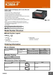
H5CX-@-NOther FeaturesChange the Front Panel ColorThe Front Panel can be replaced with an optional Front Panel (orderseparately) with a different color to match the installation site. Selectfrom black, white, and light gray.Black(standard)WhiteYou can replacethe Front Panel.Models with Instantaneous Contact OutputModels with instantaneous contact outputs have been added to thelineup for use with self-holding circuits and as auxiliary relays. Thesemodels are also convenient when replacing analog timers.Model Number StructureModel ConfigurationLight grayUniversal NPN/PNP InputDC 2-wire sensors can be connected for a wide range of inputdevices.Waterproof, Dust-proof Structure (UL508 Type4X and IP66)Worry-free application is possible in locations subject to water.Note: When the Y92S-29 Waterproof Packing is used.Key ProtectionSelect from any of seven protection patterns. Use the best one for theapplication.New ModesModes, such as a stopwatch mode (Mode S), have been added.Select any of 15 modes.H5CX SeriesStandard TypeH5CX-A SeriesEconomy TypeH5CX-L SeriesSix-digit TypeH5CX-B SeriesTypeModel H5CX-A@-N H5CX-A11@-N H5CX-L8@-N H5CX-L8E@-N H5CX-B@-NTimer Yes Yes NoFunctionTwin timer Yes Yes NoTwo-stage settings/forecast outputNo No YesOperating modesTimer Mode: 11 modesTwin Timer Mode: 4 modesTimer Mode: 4 modesTwin Timer Mode: 2 modesTimer Mode: 2 modesInput NPN/PNP input NPN input None NPN/PNP inputScrew terminalExternal connections11-pin socket 8-pin socket Screw terminal blockblockPresent value displaycharacter colorRed, green, ororangeNumber of display digits 4 6Instantaneous contacts None Provided NoneGate input Supported Not supported SupportedDIP switch settings Provided None ProvidedPower supply voltage 100 to 240 VAC or 24 VAC/12 to 24 VDC 12 to 24 VDCRed2
H5CX-@-NModel Number Legend (Not all possible combinations of functions are available.)H5CX- @@@@@-N–––––1 2 3 4 51. Type Classifier 2. External Connections 3. SettingsSymbolABLMeaningStandard type6-digit typeEconomy typeSymbolMeaningNoneScrew terminals8 8-pin socket11 11-pin socketSymbolNoneWMeaningOne stageTwo stages4. Output type5. Supply voltageSymbolMeaningNone Contact output (time-limit SPDT)Contact output (time-limitESPDT + instantaneous SPDT) *STransistor output* Can be used as a time-limit DPDT output.SymbolMeaningNone 100 to 240 VAC 50/60 HzD 12 to 24 VDC/24 VAC 50/60 Hz ** The H5CX-BWSD-N is available only for 12 to 24 VDC.Ordering InformationList of ModelsType Time specifications Operating modesH5CX-AH5CX-LH5CX-B0.001 to 9.999 s0.01 to 99.99 s0.1 to 999.9 s1 to 9999 s1 s to 99 min 59 s0.1 to 999.9 min1 to 9999 min1 min to 99 h 59 min0.1 to 999.9 h1 to 9999 h0.01 to 9999.99 s1 s to 99 h 59 min 59 s0.1 to 99999.9 min0.1 to 99999.9 hTimer ModeA: Signal ON Delay IA-1: Signal ON Delay IIA-2: Power ON Delay IA-3: Power ON Delay IIb: Repeat cycle 1b-1: Repeat cycle 2d: Signal OFF DelayE: IntervalF: CumulativeZ: ON/OFF-duty-adjustable flickerS: StopwatchTwin Timer Modetoff: Flicker OFF Start 1ton: Flicker ON Start 1toff-1: Flicker OFF Start 2ton-1: Flicker ON Start 2Timer ModeA-2: Power ON Delay Ib: Repeat cycle 1E: IntervalZ: ON/OFF-duty-adjustable flickerTwin Timer Modetoff: Flicker OFF Start 1ton: Flicker ON Start 1A: Signal ON Delay IF-1: CumulativeExternalconnectionsScrew terminals11-pin socket8-pin socketScrew terminalsNote: 1. The functions that are provided depend on the model. Check detailed specifications before ordering.2. Refer to page 33 and later for information on H5CX-B Timers (6-digit display).Inputs Outputs Supply voltage ModelsSignal, Reset,Gate (NPN/PNP inputs)Signal, Reset(NPN inputs)NoneSignal, Reset,Gate (NPN/PNP inputs)Contact output(time-limitSPDT)Transistoroutput (SPST)Contact output(time-limitSPDT)Transistoroutput (SPST)Contact output(time-limitSPDT)Transistoroutput (SPST)Contact output(time-limit SPDT+ instantaneousSPDT)Models withinstantaneouscontact outputsTransistoroutput (DPST)100 to 240 VAC H5CX-A-N12 to 24 VDC/24 VACH5CX-AD-N100 to 240 VAC H5CX-AS-N12 to 24 VDC/24 VACH5CX-ASD-N100 to 240 VAC H5CX-A11-N12 to 24 VDC/24 VACH5CX-A11D-N100 to 240 VAC H5CX-A11S-N12 to 24 VDC/24 VACH5CX-A11SD-N100 to 240 VAC H5CX-L8-N12 to 24 VDC/24 VACH5CX-L8D-N100 to 240 VAC H5CX-L8S-N12 to 24 VDC/24 VACH5CX-L8SD-N100 to 240 VAC H5CX-L8E-N12 to 24 VDC/24 VACH5CX-L8ED-N12 to 24 VDC H5CX-BWSD-N3
H5CX-@-NAccessories (Order Separately)Front Panels (Replacement Parts)Y92P-CXT4B Black (N1.5)Note: 1. You can change the color of the front panel when mounting the Timer. The Timer is shipped with a black (N1.5) Front Panel.2. "TIMER" is printed on the front of Replacement Front Panels.Soft CoverHard CoverModels Color Applicable Timers PageY92P-CXT4GFlush Mounting AdapterLight gray (5Y7/1)Y92P-CXT4S White (5Y9.2 / 0.5)Four-digit models 12Models Remarks PageY92A-48F1 --- 12Models Remarks PageY92A-48 --- 12Models Remarks PageY92F-30Y92F-45Waterproof PackingIncluded with models with terminal blocks.Use this Adapter to install the Timer in a cutoutpreviously made for a DIN 72 x 72 mm device(panel cutout: 68 x 68 mm).12Models Remarks PageY92S-29 Included with models with terminal blocks. 12Connection SocketsModels Type Connectable Timers Remarks PageP2CF-08Front ConnectingSocketP2CF-08-EFront ConnectingSocket(Finger-safe Type)H5CX-L8@Round crimp terminals cannot be used on Finger-safeSockets. Use forked crimp terminals.P2CF-11P2CF-11-EFront ConnectingSocketFront ConnectingSocket(Finger-safe Type)H5CX-A11@Round crimp terminals cannot be used on Finger-safeSockets. Use forked crimp terminals.13P3G-08P3GA-11Back Connecting SocketH5CX-L8@H5CX-A11@A Y92A-48G Terminal Cover can be used with theSocket to create a finger-safe construction.Terminal Covers for P3G-08 and P3GA-11 Back-connecting SocketsModels Remarks PageY92A-48G --- 144
H5CX-A@-N/-L@-NH5CX-A@-N/-L@-N Digital Timers• Switch the display color* between red, green, and orangeto see the output status from a distance.• Up/Down Keys for each digit enable easy operation.• Cyclic control is easy with the Twin Timer and VariableON/OFF Duty modes.* Not supported by the H5CX-A11@ or H5CX-L8@.SpecificationsRatingsItem Models H5CX-A@-N H5CX-A11@-N H5CX-L8@-NClassification Standard Type Economy TypeRatingsPower supplyvoltage *1Operating voltagefluctuation range• 100 to 240 VAC 50/60 Hz• 12 to 24 VDC/24 VAC 50/60 Hz85% to 110% of rated supply voltage (90% to 110% at 12 to 24 VDC)Power consumption Approx. 6.2 VA at 100 to 240 VAC, Approx. 5.1 VA/2.4 W at 24 VAC/12 to 24 VDC *2Mounting method Flush mounting Flush mounting, surface mounting, DIN track mountingExternal connections Screw terminals 11-pin socket 8-pin socketDegree of protectionIEC IP66, UL508 Type 4X (indoors) for panel surface only and when Y92S-29 Waterproof Packing is usedDigits4 digitsTime ranges0.001 s to 9.999 s, 0.01 s to 99.99 s, 0.1 s to 999.9 s, 1 s to 9999 s, 1 s ti 99 min 59 s0.1 m to 999.9 min, 1 min to 9999 min, 1 min to 99 h 59 min, 0.1 h to 999.9 h, 1 h to 9999 hTimer modeElapsed time (Up), remaining time (Down) (selectable)Signal, ResetInput signals Signal, Reset, Gate(no inputs on models with instantaneouscontact outputs)InputsInput methodSignal, reset, gateReset systemPower resetReset voltageSensor waiting timeOutputOutput modesOne-shot outputtimeControl outputDisplay method *3No-voltage Input ON impedance: 1 kΩ max. (Leakage current: 12 mA when 0 Ω)ON residual voltage: 3 V max.OFF impedance: 100 kΩ min.Voltage Input High (logic) level: 4.5 to 30 VDCLow (logic) level: 0 to 2 VDC (Input resistance: approx. 4.7 kΩ)No-voltage input/voltage input (switchable)Minimum input signal width: 1 or 20 ms (selectable, same for all input)No-voltage InputON impedance: 1 kΩ max.(Leakage current: 12 mA when 0 Ω)ON residual voltage: 3 V max.OFF impedance: 100 kΩ min.Power reset (depending on output mode), external reset, manual reset, automatic reset (depending on output mode)Minimum power-opening time: 0.5 s (except for A-3, b-1, F, ton-1, and toff-1 mode)10% max. of rated supply voltage250 ms max. (Control output is turned OFF and no input is accepted during sensor waiting time.)A: Signal ON Delay I, A-1: Signal ON Delay II, A-2: Power ON Delay I, A-3: Power ONDelay II, b: Repeat Cycle 1, b-1: Repeat Cycle 2, d: Signal OFF Delay, E: Interval, F:Cumulative, Z: ON/OFF-duty-adjustable flicker, S: Stopwatch, toff: Flicker OFF Start 1,ton: Flicker ON Start 1, toff-1: Flicker OFF Start 2, ton-1: Flicker ON Start 20.01 to 99.99 s• Models with Contact Outputs5 A at 250 VAC/30 VDC, resistive load (cos =1)Minimum applied load: 10 mA at 5 VDC (failure level: P, reference value)• Transistor output: NPN open collector,100 mA at 30 VDC max., residual voltage: 1.5 VDC max. (Approx. 1 V), Leakage current: 0.1 mA max.7-segment, negative transmissive LCD;Present value: 12-mm-high characters,(switchable between red,green, and orange)Set value: 6-mm-high characters,green7-segment, negative transmissive LCD;Present value: 12-mm-high characters, redSet value: 6-mm-high characters, greenModels with Instantaneous ContactOutputsA-2: Power ON Delay I, b: Repeat Cycle 1,E: Interval, Z: ON/OFF-duty-adjustableflicker, toff: Flicker OFF Start 1, ton:Flicker ON Start 1Memory backupEEPROM (overwrites: 100,000 times min.) that can store data for 10 years min.Operating temperature range -10 to 55°C (-10 to 50°C if counters are mounted side by side) (with no icing or condensation)Storage temperature range -25 to 70°C (with no icing or condensation)Operating humidity range 25% to 85%Case colorBlack (N1.5) (Optional Front Panels are available to change the Front Panel color to light gray or white.)AttachmentsWaterproof packing, flush mountingadapter, label for DIP switch settingsLabel for DIP switch settings ---*1. Do not use the output from an inverter as the power supply. The ripple must be 20% maximum for DC power.*2. Inrush current will flow for a short time when the power supply is turned ON.Inrush Current (Reference Values)Voltage Applied voltage Inrush current (peak value) Time100 to 240 VAC 264 VAC 5.3 A 0.4 ms12 to 24 VDC/24 VAC26.4 VAC 6.4 A 1.4 ms26.4 VDC 4.4 A 1.7 ms*3. The display is lit only when the power is ON. Nothing is displayed when power is OFF.5
H5CX-A@-N/-L@-NCharacteristicsAccuracy of operating timeand setting error (includingtemperature and voltageinfluences)Insulation resistanceDielectric strengthImpulse withstand voltageNoise immunityStatic immunityVibrationresistanceShockresistanceLifeexpectancyWeight* Refer to Life-test Curve.DestructionMalfunctionDestructionMalfunctionMechanicalElectricalPower-ON start: ±0.01% ±50 ms max. (See note 1.)Signal start: ±0.005%±0.03 ms max. (See note 1.)Signal start for transistor output model: ±0.005%±3 ms max. (See note1 and 2.)If the set value is within the sensor waiting time at startup the controloutput of the H5CX will not turn ON until the sensor waiting time passes.Note: 1. The values are based on the set value.2. The value is applied for a minimum pulse width of 1 ms.100 MΩ min. (at 500 VDC) between current-carrying terminal andexposed non-current-carrying metal parts, and between non-continuouscontacts2,000 VAC, 50/60 Hz for 1 min between current-carrying metal parts andnon-current-carrying metal parts2,000 VAC, 50/60 Hz for 1 min between power supply and input circuitsfor the models other than H5CX-@D-N1,000 VAC, 50/60 Hz for 1 min between control output, power supply,and input circuits for H5CX-@SD-N2,000 VAC, 50/60 Hz for 1 min between control output, power supply,and input circuits for other models1,000 VAC, 50/60 Hz for 1 min between non-continuous contacts3 kV (between power terminals) for 100 to 240 VAC, 1 kV for 24 VAC/12to 24 VDC4.5 kV (between current-carrying terminal and exposed non-currentcarryingmetal parts) for 100 to 240 VAC 1.5 kV for 24 VAC/12 to 24 VDC±1.5 kV (between power terminals) and ±600 V (between inputterminals), square-wave noise by noise simulator (pulse width: 100 ns/1 µs, 1-ns rise)Malfunction: 8 kVDestruction: 15 kV10 to 55 Hz with 0.75-mm single amplitude each in three directions for2 h each10 to 55 Hz with 0.35-mm single amplitude each in three directions for10 min each300 m/s 2 in three directions, three cycles100 m/s 2 in three directions, three cycles10,000,000 operations min. (under no load at 18,000 operations/h andambient temperature of 23°C)100,000 operations min. (5 A at 250 VAC, resistive load at 1,800operations/h and ambient temperature of 23°C) *Approx. 115 g (Timer only)Life-test Curve (ReferenceValues)Switching operations (× 10 4 )1,0005001005010DC30V L/R=7msAC250V cosφ =0.4AC250V/DC30Vcosφ =10 1 2 3 4 5Load current (A)A maximum current of 0.15 A can be switched at125 VDC (cosφ =1) and a maximum current of 0.1A can be switched if L/R is 7 ms. In both cases, alife of 100,000 operations can be expected.6
H5CX-A@-N/-L@-NApplicable StandardsApproved safety standardsEMCUL508/Listing, UL50 Type 4X for indoor use (enclosure rating), CSA C22.2 No. 14 *1 ,conforms to EN61812-1 (Pollution degree 2/overvoltage category III)B300 PILOT DUTY1/4 HP 120 VAC, 1/3 HP, 240 VAC, 5 A resistive loadVDE0106/P100CCC: Pollution degree 2, Overvoltage category II *2(EMI)EN61812-1Emission Enclosure:EN55011 Group 1 class AEmission AC mains:EN55011 Group 1 class A(EMS)EN61812-1Immunity ESD: EN61000-4-2: 6 kV contact discharge (level 2)8 kV air discharge (level 3)Immunity RF-interference: EN61000-4-3: 10 V/m (Amplitude-modulated, 80 MHz to 1 GHz) (level 3);10 V/m (Pulse-modulated, 900 MHz 5 MHz) (level 3)Immunity Conducted Disturbance: EN61000-4-6: 10 V (0.15 to 80 MHz) (level 3)Immunity Burst: EN61000-4-4: 2 kV power-line (level 3);1 kV I/O signal-line (level 4)Immunity Surge: EN61000-4-5: 1 kV line to lines (power and output lines) (level 3);2 kV line to ground (power and output lines) (level 3)Immunity Voltage Dip/Interruption: EN61000-4-11: 0.5 cycle, 100% (rated voltage)*1. The following safety standards apply to models with sockets (H5CX-A11@ or H5CX-L8@).cUL (Listing): Applicable when an OMRON P2CF (-E) Socket is used.cUR (Recognition): Applicable when any other socket is used.*2. Excluding the H5CX-ASD-N/-A11SD-N/-L8SD-N.I/O FunctionsFor details, refer to the timing charts on page 20 and page 29.Start signalNormally functions to start timing.In modes A-2 and A-3, disable timing. In mode S, starts and stops timing.• Resets present value. (In elapsed time mode, the present value returns to 0; in remaining time mode,Inputs *1the present value returns to the set value.)Reset• Count inputs are not accepted and control output turns OFF while reset input is ON.• Reset indicator is lit while reset input is ON.Gate *2Disables timing. (If a reset occurs while the gate input is ON, a reset will be performed.)Outputs Control output (OUT) Outputs take place according to designated operating mode when timer reaches corresponding set value.*1. The H5CX-L8E@ does not have an input.*2. The H5CX-L@ does not have a gate input.Response Delay Time When Resetting (Transistor Output)The following table shows the delay from when the reset signal is input until the output is turned OFF.(Reference value)Minimum reset signal widthOutput delay time1 ms 0.8 to 1.2 ms20 ms 15 to 25 ms7
H5CX-A@-N/-L@-NConnectionsBlock DiagramOutput circuit(Basic insulation)Power supplycircuit(Basic insulation)(See note.)Input circuitsInternal controlcircuitDisplay circuitKey switch circuitNote: Basic insulation is provided between the power supply circuit and the input circuits. However, basic insulation is not provided in theH5CX-@D-N.Terminal ArrangementConfirm that the power supply meets specifications before use.H5CX-A-N/-AD-NH5CX-AS-N/-ASD-N0VResetSignalGate0VResetSignalGate6 7 8 96 7 8 91 2 3 4 5(-) (+)Contact outputTerminals 1 and 6 of the H5CX-AD-Nare connected internally.H5CX-A11-N/-A11D-N1 2 3 4 5(-) (+)Transistor outputTerminals 1 and 6 of the H5CX-ASD-Nare connected internally.H5CX-A11S-N/-A11SD-NResetSignalGate56 7Unused 4 80V 392 101 11Unused(-) (+)Internal circuitContactoutputH5CX-L8-N/-L8D-NTerminals 2 and 3 of theH5CX-A11D-N areconnected internally.ResetSignalGate56 7Unused 4 80V 392 101 11Unused(-) (+)Internal circuitTransistoroutputH5CX-L8S-N/-L8SD-NTerminals 2 and 3 of theH5CX-A11SD-N areconnected internally.SignalReset4 5321 80V67Internal circuitContactoutputSignalReset34Unused562 71 80VInternal circuitTransistoroutputInstantaneouscontact outputOUT1Internal circuit(-) (+)324H5CX-L8E-N/-L8ED-N51 8(–) (+)67Terminals 1 and 2 of the H5CX-L8D-Nare connected internally.Internal circuitTime-limitcontact outputOUT2Note: Do not connect unused terminals as relay terminals.(-) (+)Transistor Output• The transistor output ofthe H5CX is insulatedfrom the internal circuitryby a photocoupler, so thetransistor output can beused as both NPN andPNP output.• The diode connected tothe collector of the outputtransistor is used toabsorb inverted voltagethat is generated when aninductive load isconnected to the H5CX.Terminals 1 and 2 of the H5CX-L8SD-Nare connected internally.NPN OutputLoad+Power for loadTimer+Power for loadPNP OutputLoad+Power for loadInductiveload8
H5CX-A@-N/-L@-NInput CircuitsSignal, Reset, and Gate InputNo-voltage Inputs (NPN Inputs)Voltage Inputs (PNP Inputs)+14 VIN1 kΩInternalcircuitINApprox. 4.7 kΩInternalcircuitInput ConnectionsThe inputs are no-voltage (closed or open) inputs or voltage inputs except for the H5CX-L8@. (The inputs of the H5CX-L8@ are no-voltage inputsonly. The H5CX-L8E@ does not have an input.)No-voltage Inputs (NPN Inputs)Open Collector Voltage Output Contact Input DC Two-wire SensorPLC orsensorSensor0 V for inputsReset inputSignal inputGate input0 V for inputsReset inputSignal inputGate input0 V for inputsReset inputSignal inputGate input0 V for inputsReset inputSignal inputGate inputH5CX-A@ 6 7 8 9H5CX-A11@ 3 7 6 5H5CX-L8@ 1 3 4 -Note: Operate with transistor ONH5CX-A@ 6 7 8 9H5CX-A11@ 3 7 6 5H5CX-L8@ 1 3 4 -Note: Operate with transistor ONH5CX-A@ 6 7 8 9H5CX-A11@ 3 7 6 5H5CX-L8@ 1 3 4 -Note: Operate with relay ONH5CX-A@ 6 7 8 9H5CX-A11@ 3 7 6 5H5CX-L8@ 1 3 4 -Note: Operate with transistor ONNo-voltage Input Signal LevelsNo-contactinputShort-circuit level Transistor ON• Residual voltage: 3 V max.• Impedance when ON: 1 kΩ max.(The leakage current is approx. 12 mA when theimpedance is 0 Ω.)Open level Transistor OFF• Impedance when OFF: 100 kΩ min.Contact input Use contacts which can adequately switch 5 mA at 10 VNote: The DC voltage must be 30 VDC max.Applicable Two-wire Sensor• Leakage current: 1.5 mA max.• Switching capacity: 5 mA min.• Residual voltage: 3.0 VDC max.• Operating voltage: 10 VDCVoltage Inputs (PNP Inputs) The inputs of the H5CX-L8@ are no-voltage inputs only.No-contact Input (NPN Transistor) No-contact Input (PNP Transistor) Contact InputSensorSensor0 V for inputsReset inputSignal inputGate input0 V for inputsReset inputSignal inputGate input0 V for inputsReset inputSignal inputGate inputH5CX-A@H5CX-A11@6 7 8 93 7 6Note: Operate with transistor OFF5H5CX-A@ 6 7 8 9H5CX-A11@ 3 7 6 5Note: Operate with transistor ONH5CX-A@ 6 7 8 9H5CX-A11@ 3 7 6 5Note: Operate with relay ONVoltage Input Signal LevelsHigh level (Input ON): 4.5 to 30 VDCLow level (Input OFF): 0 to 2 VDCNote: 1. The DC voltage must be 30 VDC max.2. Input resistance: Approx. 4.7 kΩ9
H5CX-A@-N/-L@-NNomenclatureDisplay Section1. Key Protect Indicator (orange)2. Control Output Indicator (orange)3. Reset Indicator (orange)4. Present Value Display (Main display)(Character height: 12 mm, red * )* Characters on models with screw terminals(H5CX-A@) can be switched between red,green, and orange.5. Time Unit Indicators(Color is same as present value display.)(If the time range is 0 min, 0 h, 0.0 h, or 0 h0 min, these indicators flash to indicatetiming operation.)6. Set Value Display (Sub-display)(Character height: 6 mm, green)7. Set Value 1, 2 Indicator (green)Character Sizefor PresentValue DisplayCharacter Sizefor Set ValueDisplay4516237810119Front View12 13Operation Key8. Mode Key(Changes modes and setting items)9. Reset Key(Resets present value and output)10. Up Keys 1 to 411. Down Keys 1 to 4ONSwitches12. Key-protect Switch(Default setting)OFF(Disabled)13. DIP SwitchON(Enabled)12mm6mmOFF 1 2 3 4 5 6 7 8Note: There is no DIP switch on theH5CX-L8@.DimensionsDigital TimersDigital TimersH5CX-A-N/-AS-N (Flush Mounting Models)H5CX-AD-N/-ASD-N (Flush Mounting Models)(unit: mm)48×4867848×4865944.8×44.844.8×44.8Note: M3.5 terminal screw (effective length: 6 mm)H5CX-A11@-N(Flush Mounting/Surface Mounting Models)Note: M3.5 terminal screw (effective length: 6 mm)H5CX-L8@-N (Flush Mounting/Surface Mounting Models)48×48663.714.448×48663.714.244.8×44.844.8×44.810
H5CX-A@-N/-L@-NDimensions with Flush Mounting AdapterH5CX-A-N/-AS-N (Provided with Adapter and Waterproof Packing)Y92S-29 (provided)WaterproofPackingPanelY92F-30 (provided)Flush Mounting AdapterPanel CutoutsPanel cutouts areas shown below. (accordingto DIN43700).60 min.45 +0.6058(51)45 +0.6015 min.60 min.48 7.576.5H5CX-AD-N/-ASD-N (Provided with Adapter and Waterproof Packing)58Y92S-29 (provided)WaterproofPacking(51)PanelY92F-30 (provided)Flush Mounting AdapterNote: 1. The mounting panel thicknessshould be 1 to 5 mm.2. To allow easier operation, it isrecommended that Adaptersbe mounted so that the gapbetween sides with hooks is atleast 15 mm (i.e., with thepanel cutouts separated by atleast 60 mm).3. It is possible to mount Timersside by side, but only in thedirection without the hooks.(However, if Timers aremounted side by side, waterresistance will be lost.)48 7.557.5n Units mounted side-by-sideH5CX-A11@-N (Adapter and Waterproof Packing Ordered Separately)58Y92S-29 (order separately)Waterproof Packing(51)PanelY92F-30 (order separately)Flush Mounting AdapterP3GA-11 (orderseparately)Back-connectingSocketA+1A=(48n-2.5) –0With Y92A-48F1 attached.+1A={48n-2.5+(n-1)×4}–0With Y92A-48 attached.+1A = (51n - 5.5) –0Dimensions with FrontConnecting Socket48 7.589.9H5CX*-A11@-N103.2 100.9H5CX-L8@-N (Adapter and Waterproof Packing Ordered Separately)58Y92S-29 (order separately)Waterproof Packing(51)PanelY92F-30 (order separately)Flush Mounting AdapterP3G-08 (orderseparately)Back-connectingSocketP2CF-11(-E) (order separately)Front Connecting Socket*H5CX-L8@-N92.3 9048 7.584.8P2CF-08(-E) (order separately)Front Connecting Socket* These dimensions vary with the type of DIN track(reference value).11
H5CX-A@-N/-L@-NAccessories (Order Separately)Note:Depending on the operating environment, the condition ofresin products may deteriorate, and may shrink or becomeharder. Therefore, it is recommended that resin products arereplaced regularly.Soft CoverY92A-48F1Hard CoverY92A-48Front Panel (Replacement Part)You can change the color of the front panel when mounting the Timer.The Timer is shipped with a black (N1.5) Front Panel.Y92P-CXT4SCover for Timer with 4 DigitsWhite (5Y9.2/0.5)Y92P-CXT4GCover for Timer with 4 DigitsLight gray (5Y7/1)Y92P-CXT4BCover for Timer with 4 DigitsBlack (N1.5)Replacement MethodTabsGroovesThe Front Panel is attached tothe Terminal with tabs in fourlocations. To remove the FrontPanel, open the tabs and pull theFront Panel forward.To attach the Front Panel, pressit onto the Timer so that all fourtabs lodge into the groves on thebody of the Timer.Protecting the Timer in Environments Subject to OilThe H5CX's panel surface is water-resistive (IP@6, UL Type 4X)and so even if drops of water penetrate the gaps between the keys,there will be no adverse effect on internal circuits. If, however, thereis a possibility of oil being present on the operator's hands, use theSoft Cover. The Soft Cover ensures protection equivalent to IP54against oil. Do not, however, use the H5CX in locations where itwould come in direct contact with oil.Flush Mounting AdapterY92F-30Y92F-45Order the FlushMounting Adapterseparately if it islost or damaged.Note: A FlushMountingAdapter isincluded withmodels withscrewterminals.Waterproof PackingY92S-29Note: TheWaterproofPacking isincluded withmodels withscrewterminals.Use this Adapterto install theTimer in a cutoutpreviously madefor a DIN 72 x 72mm device(panel cutout:68 x 68 mm).Order the Waterproof Packingseparately if it is lost or damaged.The Waterproof Packing can be usedto achieve IP66 protection.The Waterproof Packing will deteriorate, harden, and shrinkdepending on the application environment. To ensure maintaining theIP@6, UL Type 4X waterproof level, periodically replace theWaterproof Packing. The periodic replacement period will depend onthe application environment. You must confirm the properreplacement period. Use 1 year or less as a guideline. If theWaterproof Packing is not replaced periodically, the waterproof levelwill not be maintained.It is not necessary to mount the Waterproof Packing if waterproofconstruction is not required.12
H5CX-A@-N/-L@-NConnection SocketsFront-connecting SocketsModelDimensionsTerminal arrangementand internal connectionsMounting holedimensionsP2CF-0850 max.20.3 max.Two, 4.5-dia. holes70 max.35.4Eight, M3.5 x 7.5 sems screws7.8434.56 5 4 3Two, M4 or 4.5-dia. holesP2CF-08-E(Finger Safe Terminal)Two, 4.5-dia. holes50 max.40±0.26 54 3P2CF-08-E321.5 max.20.3197 8 1 2(Top View)40±0.2Note: The Socket canalso be mountedto DIN track.70 max.1.335.410A250VACRESISTIVE7 81 24Eight, M3.5 x 7.5 set screws7.854.5P2CF-1150 max.31.2 max.Two, 4.5-dia. holes70 max.35.4P2CF-11-E(Finger Safe TerminalType)Eleven, M3.5 x 7.5 sems screwsTwo, 4.5-dia. holes50 max.40±0.28 76 5P2CF-11-E47.843331.2 max.304.58 7 6 549 310 11 1 2(Top View)Two, M4 or 4.5-dia. holes40±0.2Note: The Socket canalso be mountedto DIN track.70 max.1.235.49310A250VACRESISTIVE10 11 1 247.8Eleven, M3.5 x 7.5 set screws54.5Note: Round crimp terminals cannot be used on Finger-safe Sockets. Use forked crimp terminals.Back-connecting SocketsModelP3G-0827 diaDimensionsTerminal arrangementand internal connections345645454.9 172 1 8 7(Bottom View)P3GA-1127 dia5 6 7 844525.63 92 1 11 10(Bottom View)454.56.216.3Note: A Y92A-48G Terminal Cover can be used with the Socket to create a finger-safe construction.13
H5CX-A@-N/-L@-NTerminal Covers for P3G-08 and P3GA-11 Back-connecting SocketsModelDimensionsY92A-48GTwelve, 6.4 dia34Y92A-48GUP47.7×47.7 48×48P C16.524.6 27.6Note: The Terminal Cover can be used with a Back-mounting Socket (P3G-08 or P3GA-11) to create a finger-safe construction.Optional Products for Track Mounting47.4Mounting TrackPFP-100NPFP-50N4.57.3±0.1535±0.327±0.1515 25 10 251,000 (500) *25 10 2515 (5) ** The values shown in parentheses are for the PFP-50N.1Mounting TrackPFP-100N24.51635±0.3272429.215 25 10 251,00025 10 25 1511.5End PlatePFP-M50M4 x 8 panhead screw106.211.81.835.5 35.311.510M4 spring washer1.34.8SpacerPFP-S5161244.334.816.5Note: Order Spacers in increments of 10.14
Operating ProceduresSetting Procedure GuideSettings for Timer Operation *Use the following settings.Settings for Twin Timer Operation *Refer to page 25.* It is not necessary to mount the Waterproof Packing if waterproof construction is not required.Operating Procedures for Timer FunctionH5CX-A@-N/-L@-NTimerStep1Settings for basic functions can be performed with just the DIP switch.Note: There is no DIP switch on the H5CX-L8@. Go to Step2 .Key-protect SwitchBe sure to set pin 1 to ON when using the DIP switch.ONOFF1 2 3 4 5 6 7 812345678Item OFF ON Pin 2 Pin 3 Pin 4Time rangeDIP switch settingsDisabled Enabled ONOFFONOFFONOFF0.001 s to 9.999 s0.01 s to 99.99 sTime rangeRefer to the table onON OFF OFF0.1 s to 999.9 sthe right.OFF ON OFF1 s to 9999 sOutput modesRefer to the table onON ON OFF 0 min 01 s to 99 min 59 sthe right.OFF OFF ON 0.1 min to 999.9 minTimer modeUP DOWNON OFF ON 0 h 01 min to 99 h 59 minInput signal width20 ms 1 msOFF ON ON0.1 h to 999.9 hNote: All the pins are factory-set to OFF. Be sure to turn ON pin 1 of the DIP switch. Changes to DIP switch settings are enabled when thepower is turned ON.(Set the DIP switch while the power is OFF.)Pin 5OFFONOFFONPin 6OFFOFFONONOutput modeMode A: Signal ON delay 1(Timer resets when power comes ON.)Mode A-2: Power ON delay 1(Timer resets when power comes ON.)Mode E: Interval(Timer resets when power comes ON.)Mode F: Cumulative(Timer does not reset when powercomes ON.)After making DIP switch settings for basic operation, advanced functions can be added using the operation keys on the front panel. Refer toStep2 on page 16 for details.15
H5CX-A@-N/-L@-NTimerStep2Settings that cannot be performed with the DIP switch are performed with the operation keys.• Change to Function Setting Mode.Power ONFor details on operations in run mode, refer to page 19.3 s min. *1 The characters displayed in reverse video are the default settings.Run modeFunction setting mode3 s min. *2*1. If the mode is switched to the function setting mode during operation, operation will continue.*2. Changes made to settings in function setting mode are enabled for the first time when the mode is changed to run mode.Also, when settings are changed, the timer is reset (time initialized and output turned OFF).When performing settings with operation keys only, set pin1 of the DIP switch to OFF (factory setting).If pin 1 of the DIP switch is set to ON, the setting items indicated in will not be displayed.Time range Set the time range using the keys.ss s ……h sFor details, refer to the Time Range List.Time Range ListDisplay Set Value0.01 s to 99.99 s(default setting)Timer mode Set the timer mode using thekeys.0.1 s to 999.9 sup(UP)down(DOWN)1 s to 9999 s Set the output mode using thekeys.0 min 01 s to99 min 59 sOutput modesa a-1 a-2 a-3 b b-1 d e f z s(A) (A-1) (A-2) (A-3) (b) (b-1) (d) (E) (F) (Z) (S)Note: Only modes A-2, b, E, and Z can be selected for models with instantaneouscontact outputs. Set each digit for the output time using the correspondingkeys.0.1 min to999.9 min1 min to9999 min0 h 01 min to99 h 59 minFunction setting modeOutput timeInput signalhold0.01(Output hold) (0.01s)~99.99(99.99s)(If the output time is set to 0.00, hold is displayed.)Note: Displayed for modes A, A-1, A-2, A-3, b, b-1 and S only. Set the input signal width using thekeys.0.1 h to 999.9 h1 h to 9999 h0.001 s to9.999 s20ms 1ms(20ms) (1ms)Note: Not displayed for models with instantaneous contact outputs.NPN/PNPinput Set the NPN/PNP mode using thekeys.npn pnp(NPN input) (PNP input)Note: Only displayed for the H5CX-A@ and H5CX-A11@.Display color Set the display color using the keys.red grn org r-g g-r r-o o-r g-o o-g(Red) (Green) (Orange) (Red-green) (Green-red) (Red-orange) (Orange-red) (Green-orange)(Orange-green)Note: Displayed only for models with terminal screws (H5CX-A@).Instantaneous/time-limit Set the function (instantaneous or time-limit operation) for the instantaneous output (output 1)using the Keys.From next page To next page1c1c 2c(Instantaneous) (Time-limit)Note: Displayed only for models with instantaneous contact outputs.16
H5CX-A@-N/-L@-NTimerFrom previouspageTo previouspageFunction setting modeSet valueupper limitKey protectlevel Set the digits for the set value limit using the corresponding keys.1 9999(1) (9999) Set the key protect level using the keys.kp-1 kp-2 kp-3 kp-4 kp-5 kp-6 kp-7(KP-1) (KP-2) (KP-3) (KP-4) (KP-5) (KP-6) (KP-7)*1Output ONcount alarmset value/monitor value*1. Set each digit for the output time using the corresponding keys.• Models without Instantaneous Contact OutputsOutput ONcount alarmset value0~9999(0 x 1000 times) (9999 x 1000 times)Output ONcount monitorvalueNote: The monitor value is only displayed.It cannot be set.• Models with Instantaneous Contact OutputsInstantaneousoutput 1(OUT1) ONcount alarmset value0(0 x 1000 times)~9999(9999 x 1000 times)Instantaneousoutput 2(OUT2) ONcount alarmset value0~9999(0 x 1000 times) (9999 x 1000 times)Instantaneousoutput 1(OUT1) ONcount monitorvalueNote: The monitor value is only displayed.It cannot be set.Instantaneousoutput 2(OUT2) ONcount monitorvalueNote: The monitor value is only displayed.It cannot be set.17
H5CX-A@-N/-L@-NTimerExplanation of FunctionsOperating Procedures for Timer FunctionItems marked with stars () can be set using the DIP switch.Time Range (timr)Set the range to be timed in the range 0.001 s to 9,999 h.Settings of type ---- h (9,999 h) and ---- min (9,999 min) cannot bemade with the DIP switch. Use the operation keys if these settings arerequired.Timer Mode (timm)Set either the elapsed time (UP) or remaining time (DOWN) mode.In UP mode, the elapsed time is displayed, and in DOWN mode, theremaining time is displayed.Output Mode (outm)Set the output mode.The possible settings are A, A-1, A-2, A-3, b, b-1, d, E, F, Z and S.Only output modes A, A-2, E, and F can be set using the DIP switch.Use the operation keys if a different setting is required.(For details on output mode operation, refer to "Timing Charts" onpage 20.)Output Time (otim)When using one-shot output, set the output time for one-shot output(0.01 to 99.99 s).One-shot output can be used only if the selected output mode is A,A-1, A-2, A-3, b, b-1 or S.If the output time is set to 0.00, hold is displayed, and the output isheld.Input Signal Width (iflt)Set the minimum signal input width (20 ms or 1 ms) for signal, reset,and gate inputs.The same setting is used for all external inputs (signal, reset, and gateinputs).If contacts are used for the input signal, set the input signal width to20 ms.Processing to eliminate chattering is performed for this setting.NPN/PNP Input Mode (imod)Select either NPN input (no-voltage input) or PNP input (voltageinput) as the input format.Set an NPN input when using a 2-wire sensor.For details on input connections, refer to "Input Connections" onpage 9.Display Color (colr)(Terminal block model: H5CX-A@ only)Set the color used for the present value.Output OFFOutput ONredRed (fixed)grnGreen (fixed)orgOrange (fixed)r-g Red Greeng-r Green Redr-o Red Orangeo-r Orange Redg-o Green Orangeo-g Orange GreenKey Protect Level (kypt)Set the key protect level.Refer to “Key Protect Level” on page 32.Instantaneous/Time-limit (otmd)Set the contact output to time-limit SPDT + instantaneous SPDT ortime-limit SPDT operation.Set Value Upper Limit (sl-h)Set the upper limit for the set value when it is set in Run Mode.The limit can be set to between 1 and 9999.This setting does not apply to the ON duty in Z mode.Output ON Count Alarm Set Value (on-a)Set the alarm value for the output ON count.The limit can be set to between 0 x 1000 (0 times) and 9999 x 1000(9,999,000 times). Only the underlined values are set. The alarm willbe disabled if 0 is set.If the total ON count of the output exceeds the alarm set value, e3 willbe displayed on the Timer to indicate that the output ON count alarmvalue was exceeded. Refer to “Self-diagnostic Function” on page32 for information on the e3 display.ON Count Alarm Set Values for Outputs 1 and 2 (OUT1and OUT2) (on1a and on2a)Set the ON count alarm values for the outputs 1 and 2.The limit can be set to between 0 x 1000 (0 times) and 9999 x 1000(9,999,000 times). Only the underlined values are set. The alarm willbe disabled if 0 is set.If the total ON count of instantaneous output 1 or 2 exceeds the alarmset value, e3 will be displayed on the Timer to indicate that the outputON count alarm value was exceeded. Refer to “Self-diagnosticFunction” on page 32 for information on the e3 display.Output ON Count Monitor Value (on-c)The monitor value is only displayed. It cannot be set.The output ON count will be 1,000 times the displayed value.ON Count Monitor Values for Outputs 1 and 2 (OUT1 andOUT2) (on1c and on2c)The monitor value for output 1 or 2 is only displayed. It cannot be set.The output ON count will be 1,000 times the displayed value.18
H5CX-A@-N/-L@-NTimerOperation in Run ModeOperating Procedures for Timer Function Set each digit for the output time using the correspondingPresent valuekeys.Set valueNote: H5CX-L8E@-N PrecautionsSet the Timer’s set value before using the Timer in a self-holding circuit. When Output Mode Z Is Selected Set each digit for the output time using the correspondingPresent value (Thekeys for the 4th digit cannot be used.)keys.ON duty ratio Set each digit for the output time using the correspondingPresent valuekeys.Cycle timePresent Value and Set ValueThese items are displayed when the power is turned ON. The presentvalue is displayed in the main display and the set value is displayedin the sub-display.The values displayed will be determined by the settings made for thetime range and the timer mode in function setting mode.Present Value and ON Duty Ratio (Output Mode = Z)The present value is displayed in the main display and the ON dutyratio is displayed in the sub-display. Set the ON duty ratio used in ON/OFF-duty-adjustable flicker mode (Z) as a percentage.Elapsed cycle timeON time = Cycle time xON duty ratio (%)100The output accuracy will vary with the time range, even if the ON dutyratio setting is the same. Therefore, if fine output time adjustment isrequired, it is recommended that the time range for the cycle time isset as small as possible.Examples: 1. When Time Range = - - - - s (9999 s)Cycle timeON duty set as a percentageUp/Down keys used for analogadjustment of the ON dutyCloseOpen31(%)20(s) x = 6.2(s)100Rounded off to the nearest integer (because of thetime range setting) → ON time = 6 s2. When Time Range = - -. - - s (99.99 s)ON duty (%)Control outputOpening/closing valveON dutyFully closed↔Fully open0%↔100%31(%)20.00(s) x = 6.200(s)100Rounded off to 2 decimal places (because of the timerange setting) → ON time = 6.20 sIf a cycle time is set, cyclic control can be performed in ON/OFF-dutyadjustableflicker mode simply by changing the ON duty ratio.Present Value and Cycle Time (Output Mode = Z)The present value is displayed in the main display and the cycle timeis displayed in the sub-display. Set the cycle time.19
H5CX-A@-N/-L@-NTimerTiming ChartsOperating Procedures for Timer FunctionModels without Instantaneous Contact OutputsThe gate input is not included in the H5CX-L8@ models.Mode A: Signal ON delay 1 (Timer resets when power comes ON.)Basic operationDetailed operationEither one-shot output or sustained output can be selected.Power*Start signalinputTimingPowerStart signalGateOutput* Start signal input is disabled during timing.ResetTiming starts when the start signal goes ON.Control outputWhile the start signal is ON, the timer starts when thepower comes ON or when the reset input goes OFF.Set valueUPThe control output is controlled using a sustained or0one-shot time period.Set valueNote: Output is instantaneous when setting is 0.DOWN0Mode A-1: Signal ON delay 2 (Timer resets when power comes ON.)Basic operationDetailed operationTiming diagramttPowerStart signalinputTimingPowerStart signalGateOutputResetTiming starts when the start signal goes ON, andresets when the start signal goes OFF.While the start signal is ON, the timer starts when theControl outputpower comes ON or when the reset input goes OFF.The control output is controlled using a sustained orSet valueUPone-shot time period.0Note: Output is instantaneous when setting is 0.Set valueDOWN0Mode A-2: Power ON delay 1 (Timer resets when power comes ON.)Basic operationDetailed operationTiming diagramtPowerPowerOutputTimingStart signalGateTiming starts when the reset input goes OFF.ResetThe start signal disables the timing function (i.e.,same function as the gate input).The control output is controlled using a sustained orControl outputone-shot time period.Set valueNote: Output is instantaneous when setting is 0.UP0Set valueDOWN0Mode A-3: Power ON delay 2 (Timer does not reset when power comes ON.)Basic operationDetailed operationTiming diagramtPowerPowerStart signalTimingSustainedt t tOutputGateTiming starts when the reset input goes OFF.The start signal disables the timing function (i.e.,same function as the gate input).The control output is controlled using a sustained orone-shot time period.Note: Output is instantaneous when setting is 0.ResetControl outputTiming diagramSet valueUP0Set valueDOWN020
H5CX-A@-N/-L@-NTimerMode b: Repeat cycle 1 (Timer resets when power comes ON.)Basic operationDetailed operationSustained OutputPowerPowerStart signal*input Timing Timing Timing TimingOutput* Start signal input is disabled during timing.Timing starts when the start signal goes ON.The status of the control output is reversed when timeis up (OFF at start).While the start signal is ON, the timer starts when thepower comes ON or when the reset input goes OFF.Note: Normal output operation will not be possible ifthe set time is too short.Set the value to at least 100 ms (contactoutput type).Start signalGateResetControl outputTiming diagramSet valueUP0Set valueDOWN0One-shot OutputPowerPowerStart signal*input Timing Timing Timing TimingStart signalOutputGate* Start signal input is disabled during timing.Timing starts when the start signal goes ON.The control output is turned ON when time is up.While the start signal is ON, the timer starts when thepower comes ON or when the reset input goes OFF.Note: Normal output operation will not be possible ifthe set time is too short.Set the value to at least 100 ms (contactoutput type).ResetControl outputTiming diagramSet valueUP0Set valueDOWN0ttMode b-1: Repeat cycle 2 (Timer does not reset when power comes ON.)Basic operationDetailed operationSustained OutputPowerStart signal*input TimingTiming SustainedTimingTiming TimingOutput* Start signal input is disabled during timing.Timing starts when the start signal goes ON.The status of the control output is reversed when timeis up (OFF at start).While the start signal is ON, the timer starts when thepower comes ON or when the reset input goes OFF.Note: Normal output operation will not be possible ifthe set time is too short.Set the value to at least 100 ms (contactoutput type).PowerStart signalGateResetControl outputTiming diagramSet valueUP0Set valueDOWN0One-shot OutputPowerStart signal*input TimingTiming SustainedTimingTiming TimingPowerStart signalOutput* Start signal input is disabled during timing.Timing starts when the start signal goes ON.The control output is turned ON when time is up.While the start signal is ON, the timer starts when thepower comes ON or when the reset input goes OFF.Note: Normal output operation will not be possible ifthe set time is too short.Set the value to at least 100 ms (contactoutput type).GateResetControl outputTiming diagramSet valueUP0Set valueDOWN0t t t tt21
H5CX-A@-N/-L@-NTimerMode d: Signal OFF delay (Timer resets when power comes ON.)Basic operationDetailed operationPower*Start signalinputTimingPowerStart signalGateOutput* Start signal input is enabled during timing.ResetThe control output is ON when the start signal is ON(except when the power is OFF or the reset is ON).The timer resets when the time is up.Note: Output functions only during start signal inputwhen setting is 0.Mode E: Interval (Timer resets when power comes ON.)Basic operationDetailed operationControl outputTiming diagramSet valueUP0Set valueDOWN0Power*Start signalinputTimingPowerStart signalGateOutput* Start signal input is enabled during timing.ResetTiming starts when the start signal comes ON.Control outputThe timer resets when the time is up.While the start signal is ON, the timer starts when theSet valuepower comes ON or when the reset input goes OFF.UP0Note: Output is disabled when the setting is 0.Set valueDOWN0Mode F: Cumulative (Timer does not reset when power comes ON.)Basic operationDetailed operationTiming diagramPowerPowerStart signalStart signalinput TimingSustained Timing GateOutputStart signal enables timing (timing is stopped when thestart signal is OFF or when the power is OFF).ResetA sustained control output is used.Note: Output is instantaneous when setting is 0.Control outputWhen the H5CX is used with power start, there will be atimer error (approximately 100 ms each time the H5CXis turned ON) due to the characteristics of the internalcircuitry. Use the H5CX with signal start if timeraccuracy is required.Set valueUP0Set valueDOWN0Mode Z: ON/OFF-duty-adjustable flicker (Timer resets when power comes ON.)Basic operationDetailed operationTiming diagramPowerPower*Start signalinputTiming(cycle time)TimingON duty(%)Timing(cycle time)TimingON duty(%)Output* Start signal input is disabled during timing.Timing starts when the start signal goes ON.The status of the control output is reversed when time isup (ON at start).While the start signal is ON, the timer starts when powercomes ON or when the reset input goes OFF.Note: Normal output operation will not be possible ifthe set time is too short.Set the value to at least 100 ms (contact outputtype).Timing diagramStart signalGateResetControl outputCycle timeUPON duty setting(%) ON time0Cycle timeON duty setting(%) ON timeDOWN022
H5CX-A@-N/-L@-NTimerMode S: Stopwatch (Timer resets when power comes ON.)Basic operationDetailed operationPowerPowerStart signalinputGate/ResetDisplay(for elapsedtime)Timing** RST flashesThe signal starts and stops timing.The display is held and timing is continued if the resetor gate input is received during timing operation.The timer resets if the reset or gate input is receivedwhen the timing operation is stopped.Note: Output is instantaneous when setting is 0.Timing diagramStart signalGate/Reset9999Set timeUP0Set timeDOWN0OutputModels with Instantaneous Contact OutputsMode A-2: Power ON delay (Timer resets when power comes ON.)Basic operationDetailed operationEither one-shot output or sustained output can be selected.PowerTimingPowert-atRtt t-a Rt t-aTime-limitoutputReset KeyInstantaneousoutputThe Timer starts when the power comes ON or whenthe reset input goes OFF.Note: Output is instantaneous when setting is 0.Time-limitcontacts, NCTime-limitcontacts, NOInstantaneouscontacts, NCInstantaneouscontacts, NOt = Set time, Rt = Reset time (0.5 s min.), t – a < t (Indicates the time is less than the set time.)Mode b: Repeat cycle 1 (Timer resets when power comes ON.)Basic operationDetailed operationPowert (time) t (time) t (time) t (time)Powert-a t t t t-a Rt t t t t-a t-a Rt t-aTime-limitoutputReset KeyInstantaneousoutputThe Timer starts when the power comes ON or whenthe reset input goes OFF.Note: Normal output operation will not be possible ifthe set time is too short.Set the value to at least 100 ms.Time-limitcontacts, NCSustained OutputTime-limitcontacts, NOTime-limitcontacts, NCOne-shot OutputTime-limitcontacts, NOInstantaneouscontacts, NCInstantaneouscontacts, NOt = Set time, Rt = Reset time (0.5 s min.), t – a < t (Indicates the time is less than the set time.)Note: H5CX-L8E@-N PrecautionsSet the Timer’s set value before using the Timer in a self-holding circuit.23
H5CX-A@-N/-L@-NTimerMode E: Interval (Timer resets when power comes ON.)Basic operationDetailed operationPowerTimingPowert-atRtt t-a Rt t-aTime-limitoutputReset KeyInstantaneousoutputThe Timer starts when the power comes ON or whenthe reset input goes OFF.Note: Output is not instantaneous when setting is 0.Time-limitcontacts, NCTime-limitcontacts, NOInstantaneouscontacts, NCInstantaneouscontacts, NOt = Set time, Rt = Reset time (0.5 s min.), t – a < t (Indicates the time is less than the set time.)Mode Z: ON/OFF-duty adjustable flicker (Timer resets when power comes ON.)Basic operationDetailed operationPowerTiming (cycle time)Timing (cycle time)Powert-att-aRttt-adty dty dty dtyt-aRtt-aTime-limitoutputTiming(ON duty)Timing(ON duty)Reset KeyInstantaneousoutputThe Timer starts when the power comes ON or whenthe reset input goes OFF.Note: Normal output operation will not be possible ifthe set time is too short.Set the value to at least 100 ms.Time-limitcontacts, NCTime-limitcontacts, NOInstantaneouscontacts, NCInstantaneouscontacts, NONote: H5CX-L8E@-N PrecautionsSet the Timer’s set value before using the Timer in a self-holding circuit.t = Set time, dty = ON duty time, Rt = Reset time (0.5 s min.), t – a < t (Indicates the time is less than the set time.)24
H5CX-A@-N/-L@-NTwin TimerSetting Procedure GuideOperating Procedures for Twin Timer FunctionStep1Switching to a Twin TimerPower ONRun mode+ 1Hold down for 1 s min.+ 1Hold down for 1 s min.Timer/twin timerselection modePress the or Key toswitch to a Twin Timer.timTimertwnTwin timerStep2Settings for basic functions can be performed with just the DIP switch.Note: There is no DIP switch on the H5CX-L8@. Go to Step3 .Key-protect SwitchBe sure to set pin 1 to ON when using the DIP switch.ONOFF1 2 3 4 5 6 7 8Item OFF ON Pin 2 Pin 3OFF time range12DIP switch settings Disabled Enabled OFFON34OFF time range Refer to the table on the right.OFFON5ON time rangeRefer to the table on the right.6 Output mode Flicker OFF start Flicker ON startPin 47 Timer modeUPDOWNOFF8 Input signal width 20 ms 1 msONNote: All the pins are factory-set to OFF.OFFON Be sure to turn ON pin 1 on the DIP switch. Changes to DIP switch settings are enabled when the power is turned ON.(Perform DIP switch settings while the power is OFF.)OFFOFFONONPin 5OFFOFFONON0.01 s to 99.99 s0.1 s to 999.9 s1 s to 9999 s0 min 01 s to 99 min 59 sON time range0.01 s to 99.99 s0.1 s to 999.9 s1 s to 9999 s0 min 01 s to 99 min 59 sAfter making DIP switch settings for basic operation, advanced functions can be added using the operation keys on the front panel. Refer toStep3 on page 26 for details.25
H5CX-A@-N/-L@-NTwin TimerTo switch to twin timer operation, use the procedure given below. For details, refer to page 31.Step3Settings that cannot be performed with the DIP switch are performed with the operation keys.• Change to Function Setting Mode.Power ONFor details on operations in run mode, refer to page 28.3 s min. *1Run modeFunction setting mode3 s min. *2*1. If the mode is switched to the function setting mode during operation, operation will continue.*2. Changes made to settings in function setting mode are enabled for the first time when the mode is changed to run mode.Also, when settings are changed, the timer is reset (time initialized and output turned OFF).The characters displayed in reverse video are the default settings.When performing settings with operation keys only, set pin1 of the DIP switch to OFF (factory setting).If pin 1 of the DIP switch is set to ON, the setting items indicated in will not be displayed.OFF timerange Set the OFF time range using the keys.ss s ……h sTime Range ListDisplay Set ValueFor details, refer to Time Range List.0.01 s to 99.99 s(default setting)ON timerange Set the ON time range using the keys.ss s ……h s0.1 s to 999.9 s1 s to 9999 sFor details, refer to Time Range List.0 min 01 s to99 min 59 sTimer mode Set the timer mode using theup down(UP) (DOWN)keys.0.1 min to999.9 min1 min to9999 minFunction setting modeON/OFFstart modeInput signalwidth Set the twin timer output mode using the keys.toff ton tof1 ton1Flicker Flicker Flicker Flicker( OFF start 1) ( On Start 1) ( OFF start 2) ( On Start 2 )Note: Only Flicker OFF Start 1 or Flicker ON Start 1 can be selected for the H5CX-L8E@. Set the input signal width using the keys.20ms 1ms(20 ms) (1 ms)Note: Not displayed for models with instantaneous contact outputs.0 h 01 min to99 h 59 min0.1 h to 999.9 h1 h to 9999 h0.001 s to9.999 sNPN/PNPinput Set the NPN/PNP input mode using the keys.npn pnp(NPN input) (PNP input)Note: Displayed only for the H5CX-A@ and H5CX-A11@.Displaycolor Set the display color using the keys.red grn org r-g g-r r-o o-r g-o o-g(Red) (Green) (Orange) (Red-green) (Green-red) (Red-orange) (Orange-red) (Green-orange) (Orange-green)Note: Displayed only for models with terminal screws (H5CX-A@).Instantaneous/time-limit Set the function (instantaneous or time-limit operation) for the instantaneous output (output 1)using the Keys.To next page From next page1c1c 2c(Instantaneous) (Time-limit)Note: Displayed only for models with instantaneous contact outputs.26
H5CX-A@-N/-L@-NTwin TimerFrom previouspageTo previouspageSet valueupper limit 1 Set the digits for the set value limit using the corresponding1 9999(1) (9999)keys.Function setting modeSet valueupper limit 2Key protectlevel Set the digits for the set value limit using the corresponding keys.1 9999(1) (9999) Set the key protect level using the keys.kp-1 kp-2 kp-3 kp-4 kp-5 kp-6 kp-7(KP-1) (KP-2) (KP-3) (KP-4) (KP-5) (KP-6) (KP-7)*1Output ONcount alarmset value/monitor value*1. Set the digits for the output ON alarm set value using the correspondingkeys.• Models without Instantaneous Contact OutputsOutput ONcount alarmset value0~9999(0 x 1000 times) (9999 x 1000 times)Output ONcount monitorvalueNote: The monitor value is only displayed.It cannot be set.• Models with Instantaneous Contact OutputsInstantaneousoutput 1(OUT1) ONcount alarmset value0~9999(0 x 1000 times) (9999 x 1000 times)Instantaneousoutput 2(OUT2) ONcount alarmset value0~9999(0 x 1000 times) (9999 x 1000 times)Instantaneousoutput 1(OUT1) ONcount monitorvalueNote: The monitor value is only displayed.It cannot be set.Instantaneousoutput 2(OUT2) ONcount monitorvalueNote: The monitor value is only displayed.It cannot be set.27
H5CX-A@-N/-L@-NTwin TimerExplanation of FunctionsOperating Procedures for Twin Timer FunctionItems marked with stars () can be set using the DIP switch.OFF Time Range (oftr)Set the time range for the OFF time in the range 0.000 s to 9,999 h.Only settings of type --.-- s (99.99 s), ---.- s (999.9 s), ---- s (9,999 s),and -- min -- s (99 min 59 s) can be made with the DIP switch. Use theoperation keys if another type of setting is required.ON Time Range (ontr)Set the time range for the ON time in the range 0.001 s to 9,999 h.Only settings of type --.-- s (99.99 s), ---.- s (999.9 s), ---- s (9,999 s),and -- min -- s (99 min 59 s) can be made with the DIP switch. Use theoperation keys if another type of setting is required.Timer Mode (timm)Set either the elapsed time (UP) or remaining time (DOWN) mode.In UP mode, the elapsed time is displayed, and in DOWN mode, theremaining time is displayed.ON/OFF Start Mode (totm)Set the output mode.Set either flicker OFF start or flicker ON start. (For details on outputmode operation, refer to "Timing Charts" on page 29.)Input Signal Width (iflt)Set the minimum signal input width (20 ms or 1 ms) for signal, reset,and gate inputs.The same setting is used for all external inputs (signal, reset, and gateinputs).If contacts are used for the input signal, set the input signal width to20 ms.Processing to eliminate chattering is performed for this setting.Operation in Run ModeOperating Procedures for Twin Timer FunctionNPN/PNP Input Mode (imod)Select either NPN input (no-voltage input) or PNP input (voltage input)as the input format. Set an NPN input when using a 2-wire sensor.The same setting is used for all external inputs.For details on input connections, refer to "Input Connections" onpage 9.Display Color (colr)(Terminal black model: H5CX-A@ only)Set the color used for the present value.Output OFFOutput ONredRed (fixed)grnGreen (fixed)orgOrange (fixed)r-g Red Greeng-r Green Redr-o Red Orangeo-r Orange Redg-o Green Orangeo-g Orange GreenKey Protect Level (kypt)Set the key protect level.Refer to “Key Protect Level” on page 32.Present valueOFF set time Set the digits for the OFF set time using the correspondingkeys.Present valueON set time Set the digits for the OFF set time using the correspondingkeys.Note: 1. The display will automatically show the OFF set time when the OFF time is being timed and the ON set time when the ON time is being timed.Note: 2. H5CX-L8E@-N PrecautionsSet the Timer’s set value before using the Timer in a self-holding circuit.Present Value and OFF Set TimeThe present value is displayed in the main display and the OFF settime is displayed in the sub-display. Set the OFF time.Present Value and ON Set TimeThe present value is displayed in the main display and the ON settime is displayed in the sub-display. Set the ON time.28
H5CX-A@-N/-L@-NTwin TimerTiming ChartsOperating Procedures for Timer FunctionModels without Instantaneous Contact OutputsThe gate input is not included in the H5CX-L8@ models.Mode toff: Flicker OFF start 1 (Timer resets when power comes ON.)Basic operationDetailed operationPowerPower*Start signalinputTimingOFFTimingONTimingOFFTimingONStart signalGateOutput* Start signal input is disabled during timing.Timing starts when the start signal goes ON.The status of the control output is reversed when time isup (OFF at start).While the start signal is ON, the timer starts when thepower comes ON or when the reset input goes OFF.Note: Normal output operation will not be possible ifthe set time is too short.Set the value to at least 100 ms (contact outputtype).ResetControl outputTiming diagramOFF timeUPON time0OFF timeDOWNON time0Mode ton: Flicker OFF start 1 (Timer resets when power comes ON.)Basic operationDetailed operationPowerPower*Start signalinputTimingONTimingOFFTimingONTimingOFFStart signalGateOutput* Start signal input is disabled during timing.Timing starts when the start signal goes ON.The status of the control output is reversed when time isup (ON at start).While the start signal is ON, the timer starts when thepower comes ON or when the reset input goes OFF.Note: Normal output operation will not be possible ifthe set time is too short.Set the value to at least 100 ms (contact outputtype).ResetControl outputTiming diagramOFF timeUPON time0OFF timeDOWNON time0Mode toff-1: Flicker OFF start 2 (Timer does not reset when power comes ON.)Basic operationDetailed operationPowerPower*Start signalinputTimingOFFTimingONTimingOFFabStart signalGateOutput* Start signal input is disabled during timing.(a + b = ON time)Timing starts when the start signal goes ON.The status of the control output is reversed when time isup (OFF at start).While the start signal is ON, the timer starts when thepower comes ON or when the reset input goes OFF.Note: Normal output operation will not be possible ifthe set time is too short.Set the value to at least 100 ms (contact outputtype).ResetControl outputTiming diagramOFF timeUPON time0OFF timeDOWNON time029
H5CX-A@-N/-L@-NTwin TimerMode ton-1: Flicker ON start 2 (Timer does not reset when power comes ON.)Basic operationDetailed operationPowerPower*Start signalinputTimingONTimingOFFTimingONabStart signalGateOutput* Start signal input is disabled during timing.(a + b = OFF time)Timing starts when the start signal goes ON.The status of the control output is reversed when time isup (ON at start).While the start signal is ON, the timer starts when thepower comes ON or when the reset input goes OFF.Note: Normal output operation will not be possible ifthe set time is too short.Set the value to at least 100 ms (contact outputtype).ResetControl outputTiming diagramOFF timeUPON time0OFF timeDOWNON time0Models with Instantaneous Contact OutputsMode toff: Flicker OFF start 1 (Timer resets when power comes ON.)Basic operationDetailed operationt-a t-off t-on t-off t-b Rt t-off t-on t-off t-b t-a Rt t-aPowerToff timeTon timeToff timeTon timePowerTime-limitoutputInstantaneousoutputThe Timer starts when the power comes ON or whenthe reset input goes OFF.Note: Normal output operation will not be possible ifthe set time is too short.Set the ON time and OFF time to at least 100ms.Reset KeyTime-limitcontacts, NCTime-limitcontacts, NOInstantaneouscontacts, NCInstantaneouscontacts, NOt-on = ON time, t-off = OFF time, Rt = Reset time (0.1 s min.), t – a < t-off and t – b < t-on(Indicates the time is less than the set time.)Mode ton: Flicker ON start 1 (Timer resets when power comes ON.)Basic operationDetailed operationt-b t-on t-off t-on t-a Rt t-on t-off t-on t-a t-b Rt t-bPowerTon timeToff timeTon timeToff timePowerTime-limitoutputInstantaneousoutputThe Timer starts when the power comes ON or whenthe reset input goes OFF.Note: Normal output operation will not be possible ifthe set time is too short.Set the ON time and OFF time to at least 100ms.Reset KeyTime-limitcontacts, NCTime-limitcontacts, NOInstantaneouscontacts, NCInstantaneouscontacts, NOt-on = ON time, t-off = OFF time, Rt = Reset time (0.1 s min.), t – a < t-off and t – b < t-on(Indicates the time is less than the set time.)Note: H5CX-L8E@-N PrecautionsSet the Timer’s set value before using the Timer in a self-holding circuit.30
H5CX-A@-N/-L@-NTimer/Twin Timer Selection Mode (Function Selection)Select whether the H5CX is used as a timer or a twin timer in timer/twin timer selection mode.The H5CX is also equipped with a DIP switch monitor function, a convenient function that enables the settings of the DIP switch pins to beconfirmed using the front display.Power ONKey1KeyRun modeCaution+11 s min.*2 *1To change the mode to timer/twin timer selection mode,hold down the 1 key for 1 s min. with the key helddown. The 1 key must be pressed before the key. If thekey is pressed first, the mode will not change.Timer/Twin Timer Selection ModeTimer/Twintimer selectionDIP switchmonitorConvenientSelect either tim timer operation or twn twin timer operation using thekeys.Note: The H5CX is factory-set for timer operation.Confirm the status of DIP switch pins 1 to 8 using theNote: 1. This display is not supported with H5CX-L8@-N.2. This display is only possible when DIP switch pin 1 (DIP switch settingsenable/disable) is set to ON (enable).ExampleONkeys.OFF1 2 3 4 5 6 7 8Indicates that DIP switch pin 8 is ON.Indicates that DIP switch pin 7 is OFF.Indicates that DIP switch pin 6 is ON.Indicates that DIP switch pin 5 is OFF.Indicates that DIP switch pin 4 is ON.Indicates that DIP switch pin 3 is OFF.Indicates that DIP switch pin 2 is ON.Indicates that DIP switch pin 1 is ON.*1. When the mode is changed to timer/twin timer selection mode, the present value is reset and output turns OFF.Timing operation is not performed in timer/twin timer selection mode.*2. Setting changes made in timer/twin timer selection mode are enabled when the mode is changed to run mode.If settings are changed, the HC5X is automatically reset (present value initialized, output turned OFF).31
H5CX-A@-N/-L@-NKey Protect LevelWhen the key-protect switch is set to ON, it is possible to prevent setting errors by prohibiting the use of certain operation keys by specifying thekey protect level (KP-1 to KP-7).The key protect indicator is lit while the key-protect switch is set to ON.OFF *(Disabled)ON(Enabled)* Factory-set to OFFKey protect indicatorLevelMeaningChanging mode*DetailsSwitching displayduring operationReset KeyUp/down keyKP-1(default setting)Invalid Valid Valid ValidKP-2 Invalid Valid Invalid ValidKP-3 Invalid Valid Valid InvalidKP-4 Invalid Valid Invalid InvalidKP-5 Invalid Invalid Invalid InvalidKP-6 Invalid Invalid Valid ValidKP-7 Invalid Invalid Invalid Valid* Changing mode to Timer/Twin Timer Selection Mode or Function Setting Mode.Self-diagnostic FunctionThe following displays will appear if an error occurs.Main display Sub-display Error Output status Correction method Set value after resete1 Not lit CPU OFFEither press the reset key orreset the power supply.No changee2 Not lit Memory error (RAM) OFF Reset the power supply. No changee2 sum Memory error EEPROM *1 OFF Reset Key Factory settinge3 *2No changeOutput ON count alarm setvalue exceededNo change Reset Key No change*1. This includes times when the life of the EEPROM has expired.*2. The normal display and e3 will appear alternately.When the Reset Key is pressed, e3 will no longer be displayed even if the alarm set value is exceeded. (Monitoring is possible, however, because the Timer willcontinue without clearing the output ON count.)32
H5CX-B@-N• H5CX Digital Timers with 6-digit Display, 2-stage Setting,and Forecast Output (DIN 48 x 48-mm)• Times the daily operating hours of machinery and tools,predicting and notifying when maintenance is required.• Easy-to-read backlit negative LCD with 6 digits (displaysto 99999.9 h).• The 2-stage settings and forecast output are ideal formaintenance applications.SpecificationsRatingsClassificationDigital Timer H5CX-B@-NPower supply voltage*1. Inrush current will flow for a short time when the power supply is turned ON.Inrush Current (Reference Values)Voltage Applied voltage Inrush current (peak value) Time12 to 24 VDC 26.4 VDC 4.4 A 1.7 ms*2. The display is lit only when the power is ON.Digital Timer with 6-digit display, 2-stage setting, and forecast output12 to 24 VDCRatingsOperating voltagefluctuation range90% to 110% rated supply voltagePower consumption Approx. 2.3 W *1Mounting methodFlush mountingExternal connectionsScrew terminalsDegree of protectionIEC IP66, UL508 Type 4X (indoors) for panel front surface only and only when Y92S-29 Waterproof Packing is usedDigits6 digitsTime range0.01 s to 9999.99 s, 1 s to 99 h 59 min 59 s, 0.1 min to 99999.9 min, 0.1 h to 99999.9 hTimer modeElapsed time (Up)Input signalsSignal, reset, gateNo-voltage Input ON impedance : 1 kΩ max. (Leakage current: 12 mA when 0 Ω)ON residual voltage : 3 V max.Inputs Input methodOFF impedance : 100 kΩ min.Voltage Input High (logic) level : 4.5 to 30 VDCLow (logic) level : 0 to 2 VDC (Input resistance: approx. 4.7 kΩ)No-voltage (NPN) input/voltage (PNP) input (switchable)Signal, reset, gate Minimum input signal width: 1 or 20 ms (selectable, same for all input)Reset systemPower resets (only for A mode), external and manual resetPower resetMinimum power-opening time: 0.5 s (except for F-1 mode)Reset voltage10% max. of rated supply voltageSensor waiting time250 ms max. (Control output is turned OFF and no input is accepted during sensor waiting time.)Output modes A, F-1OutputsTransistor output: NPN open collector, 100 mA at 30 VDC max. residual voltage: 1.5 VDC max. (Approx. 1 V)Output typeLeakage current: 0.1 mA max.7-segment, negative transmissive LCD;DisplayPresent value: 10-mm-high characters, redSet value: 6-mm-high characters, green *2Memory backupEEPROM (overwrites: 100,000 times min.) that can store data for 10 years min.Operating temperature range -10 to 55°C (-10 to 50°C if counters are mounted side by side) (with no icing or condensation)Storage temperature range-25 to 70°C (with no icing or condensation)Operating humidity range 25 to 85%Case colorBlack (N1.5)AttachmentsWaterproof packing, flush mounting adapter, unit label33
H5CX-B@-NCharacteristicsAccuracy of operating timeand setting error(including temperature andvoltage influences)Insulation resistanceDielectric strengthImpulse withstand voltageNoise immunityStatic immunityVibrationresistanceShockresistanceWeightDestructionMalfunctionDestructionMalfunctionPower-ON start: ±0.01% ±50 ms max. (See note 1.)Signal start: ±0.005%±0.03 ms max. (See note 1.)Signal start for transistor output model: ±0.005%±3 ms max. (See note 1 and 2.)If the set value is within the sensor waiting time at startup the control output of the H5CX will not turn ON until the sensor waitingtime passes.Note: 1. The values are based on the set value.2. The value is applied for a minimum pulse width of 1 ms.100 MΩmin. (at 500 VDC) between current-carrying terminal and exposed non-current-carrying metal parts2,000 VAC, 50/60 Hz for 1 min between current-carrying metal parts and non-current-carrying metal parts1,000 VAC, 50/60 Hz for 1 min between control output, power supply, and input circuit1.0 kV (between power terminals)1.5 kV (between current-carrying terminal and exposed non-current-carrying metal parts)±480 V (between power terminals) and ±600 V (between input terminals), square-wave noise by noise simulator(pulse width: 100 ns/1 µs, 1-ns rise)Destruction: 15 kVMalfunction: 8 kV10 to 55 Hz with 0.75-mm single amplitude in three directions for 2 h each10 to 55 Hz with 0.35-mm single amplitude in three directions for 10 min each300 m/s 2 in three directions, three cycles100m/s 2 in three directions, three cyclesApprox. 105 g (Timer only)Applicable StandardsApproved safety standardsEMCUL508/Listing, CSA C22.2 No. 14, conforms to EN 61812-1 (pollution degree 2/overvoltage category III)Conforms to VDE0106/P100 (finger protection).(EMI)Emission Enclosure:(EMS)Immunity ESD:Immunity RF-interference:Immunity Conducted Disturbance:Immunity Burst:Immunity Surge:EN61812-1EN55011 Group 1 class AEN61812-1EN61000-4-2: 6 kV contact discharge (level 2)8 kV air discharge (level 3)EN61000-4-3: 10 V/m (Amplitude-modulated, 80 MHz to 1 GHz) (level 3);10 V/m (Pulse-modulated, 900 MHz 5 MHz) (level 3)EN61000-4-6: 10 V (0.15 to 80 MHz) (level 3)EN61000-4-4: 2 kV power-line (level 3);1 kV I/O signal-line (level 4)EN61000-4-5: 1 kV line to lines (power and output lines) (level 3);2 kV line to ground (power and output lines) (level 3)I/O FunctionsInputsOutputsStart signalResetGateForecast valuesettingAbsolute valuesettingStarts timing.• Resets present value. (The present value returns to 0.)• Timing stops and control output turns OFF while reset input is ON.• Reset indicator is lit while reset input is ON.Inhibits timer operation.Control output (OUT2) Turns ON when the present value reaches the set value.Forecast output (OUT1) Turns ON when the present value reaches the forecast value.Control output 2 (OUT2) Turns ON when the present value reaches set value 2.Control output 1 (OUT1) Turns ON when the present value reaches set value 1.Response Delay Time When Resetting (Transistor Output)The following table shows the delay from when the reset signal is input until the output is turned OFF.(Reference value)Minimum reset signal widthOutput delay time1 ms 0.8 to 1.2 ms20 ms 15 to 25 ms34
ConnectionsBlock DiagramOutput circuit(Basic insulation)Input circuitsInternal controlcircuitPower supplycircuitDisplay circuitKey switchcircuitInput CircuitsSignal, Reset, and Gate InputNo-voltage Inputs (NPN Inputs)IN1 kΩ+14 VInternalcircuitH5CX-B@-NVoltage Inputs (PNP Inputs)INApprox. 4.7 kΩInternalcircuitTerminal Arrangement(–)0 VReset6 7 8 9 10(+)SignalGate12 13 OUT 11 2 3 4 5OUT 2ResetNote: 1. The power supply and input circuitare not isolated.2. Terminals 1 and 6 are connectedinternally.3. Terminals 7 and 10 have the samereset function. The same function willbe performed whichever terminal isconnected. Terminals 7 and 10 arenot connected internally, however, sodo not use them for cross-over wiring.Input ConnectionsThe inputs of the H5CX-B are no-voltage (short-circuit or open) inputs or voltage inputs.No-voltage Inputs (NPN Inputs)Transistor Output• The transistor output ofthe H5CX is insulatedfrom the internal circuitryby a photocoupler, so thetransistor output can beused as both NPN andPNP output.• The diode connected tothe collector of the outputtransistor is used toabsorb inverted voltagethat is generated when aninductive load isconnected to the H5CX.NPN OutputLoad+Power for loadTimer+Power for loadOpen Collector Voltage Output Contact Input DC Two-wire SensorPNP OutputLoad+Power for loadInductiveloadPLC orsensorSensor0 V for inputsResetSignalGateReset0 V for inputsResetSignalGateReset0 V for inputsResetSignalGateReset0 V for inputsResetSignalGateReset6 7 8 9 106 7 8 9 106 7 8 9 106 7 8 9 10Note: Operate with transistor ONNote: Operate with transistor ONNote: Operate with relay ONNote: Operate with transistor ONNo-voltage Input Signal LevelsNo-contactinputContact inputShort-circuit level (Transistor ON)• Residual voltage: 3 V max.• Impedance when ON: 1 kΩ max.(The leakage current is approx. 12 mA when the impedance is 0 Ω.)Open level (Transistor OFF)• Impedance when OFF: 100 kΩ min.Use contacts which can adequately switch 5 mA at 10 VVoltage Inputs (PNP Inputs)No-contact Input (NPN Transistor) No-contact Input (PNP Transistor) Contact InputApplicable Two-wire Sensor• Leakage current: 1.5 mA max.• Switching capacity: 5 mA min.• Residual voltage: 3.0 VDC max.• Operating voltage: 10 VDCSensorSensor0 V for inputsResetSignalGateReset0 V for inputsResetSignalGateReset0 V for inputsResetSignalGateReset6 7 8 9 10Note: Operate with transistor OFFVoltage Input Signal LevelsHigh level (Input ON): 4.5 to 30 VDCLow level (Input OFF): 0 to 2 VDCNote: 1. The DC voltage must be 30 VDC max.2. Input resistance: Approx. 4.7 kΩ6 7 8 9 10Note: Operate with transistor ON6 7 8 9 10Note: Operate with relay ON35
H5CX-B@-NNomenclatureDisplay Section1. Key Protection Indicator (orange)Lit when the reset input or Reset Key is ON.2. Control Output Indicator (orange)Forecast value settingForecast output ON: OUT 1 is lit.Control output ON: OUT 2 is lit.Absolute value settingControl output 1 ON: OUT 1 is lit.Control output 2 ON: OUT 2 is lit.3. Reset Indicator (orange)Lit when the reset input or Reset Key is ON.4. Present Value Display (red)Character height: 10 mmIf the time range is 0.0 min or 0.0 h, the decimalpoint flashes to indicate timing operation.5. Time Unit Indicators (green)6. Set Value (green)Character height: 6 mm7. Set Value 1, 2 Indicator (green)Character Sizefor PresentValue DisplayCharacter Sizefor Set ValueDisplay12389Sixth digitFirst digit11 12456710Operation Key8. Mode Key(Changes modes and setting items)9. Reset KeyResets present value and output.10. Up Keys 1 to 6Switches11. Key-protect Switch(Default setting)OFF(Disabled)12. DIP SwitchONOFF1 2 3 4 5 6 7 8ON(Enabled)10mm6mmKey Protect LevelWhen the Key-protect Switch is ON, key operations are prohibitedaccording to the settings for DIP switch pins 6 to 8, thus preventingsetting errors.The Key-protect Switch can be turned ON and OFF while the poweris ON.DimensionsDigital TimersDigital TimersH5CX-BWSD-N (Flush Mounting Models)48×48659The Key Protection Indicator is lit orange when the Key-protect Switchis ON.If the key protect switch is ON, you will not be able to switch toFunction Setting Mode.(unit: mm)Panel CutoutsPanel cutouts areas shown below. (accordingto DIN43700)60 min.45 +0.6–045 +0.6–044.8×44.815 min.60 min.Note: M3.5 terminal screw (effective length: 6 mm)Dimensions with Flush Mounting AdapterH5CX-BWSD-N (Provided with Adapter and Waterproof Packing)Y92S-29 (provided)Waterproof PackingPanelY92F-30 (provided)Flush Mounting AdapterNote: 1. The mounting panel thickness shouldbe 1 to 5 mm.2. To allow easier operation, it isrecommended that Adapters bemounted so that the gap betweensides with hooks is at least 15 mm(i.e., with the panel cutouts separatedby at least 60 mm).3. It is possible to mount Timers side byside, but only in the direction withoutthe hooks. However, if Timers aremounted side by side, waterresistance will be lost.n side by side mountingAccessories (Order Separately)Refer to page 12 for details.58(51)48 7.5 57.5AA= (48n–2.5) +1–0With Y92A-48F1 attached.A={48n–2.5+(n–1)×4} +1–0With Y92A-48 attached.A= (51n–5.5)–0+136
H5CX-B@-NOperating ProceduresDIP Switch SettingsAll functions are set using the DIP switch.Item OFF ON1 Refer to the table on theTime range2right.3 Output modes F-1 mode A mode4 Input signal width 20 ms 1 ms5 NPN/PNP input modeNPN(no-voltage)PNP(voltage)6 Reset Key protection Disabled Enabled7 Up Key protection Disabled Enabled8 Mode Key protection Disabled EnabledNote: 1. All the pins are factory-set to OFF.2. DIP switch settings are effective when the power isturned ON again. (Set the DIP switch before installationand power-up.)Pin 1 Pin 2 Time rangeOFF OFF 0.1 h to 99999.9 hON OFF 0.01 s to 9999.99 sOFF ON0 h 00 min 01 s to99 h 59 min 59 sON ON 0.1 min to 99999.9 minONOFF1 2 3 4 5 6 7 8Operation in Run ModeSet the digits for the set values using the correspondingKey.Forecast Value SettingAbsolute Value SettingPresent valueSet value Each time the Key is pressed,the sub-display will switch betweenthe set value (“SET” is lit) and theforecast set value (“1” is lit).Present valueForecast set valuePresent valueSet value 1Each time the Key is pressed,the sub-display will switch betweenset value 1 (“SET 1” is lit) and setvalue 2 (“SET 2” is lit).Present valueSet value 237
H5CX-B@-NOperation in Function Setting ModeSettings that cannot be performed with the DIP switch are performed with the operation keys.• Change to Function Setting Mode.Power ON3 s min. *1Run modeFunction setting mode3 s min. *2*1. If the mode is switched to the function setting mode during operation, operation will continue.*2. Changes made to settings in function setting mode are enabled for the first time when the mode is changed to run mode.Also, when settings are changed, the timer is reset (time initialized and output turned OFF).Absolute Set the digits for the set values using thevalue setting/forecast valuesettingcorresponding Key.~(Forecast (Absolutevalue setting) value setting)Set valueupper limitSet the digits for the set values using thecorresponding Key.~(1) (999999)Forecastsetting upperlimitSet the digits for the set values using thecorresponding Key.~(1) (999999)Note: Displayed only in forecast setting mode.Function Setting ModeOutput 1(OUT1)ON countalarm set valueSet the digits for the set values using thecorresponding Key.(0 x 1000times)~(9999 x 1000times)Output 2(OUT2)ON countalarm set valueSet the digits for the set values using thecorresponding Key.(0 x 1000times)~(9999 x 1000times)Output 1(OUT1)ON countmonitor valueNote: The monitor value is only displayed. It cannot be set.Output 2(OUT2)ON countmonitor valueNote: The monitor value is only displayed. It cannot be set.38
H5CX-B@-NExplanation of FunctionsAbsolute value setting/forecast value setting(setm)Set value 1 can be set as the forecast value setting (ofst) or theabsolute value setting (abs).Forecast Value SettingForecastset valueSetvalueForecastvalue0Forecast output(OUT1)Control output(OUT 2)Example: F-1 ModePresentvalue• OUT1 (forecast output) turns ON when the present value reachesthe forecast value.Forecast value = Set value - Forecast set valueNote: The forecast set value is used to set the deviation for the set value.• OUT2 (control output) turns ON when the present value reachesthe set value.• If the forecast set value ≥ set value, OUT1 (forecast output) will turnON as soon as timing starts.Self-diagnostic FunctionThe following displays will appear if an error occurs.Absolute Value SettingSet value 2Set value 1• OUT1 (control output 1) turns ON when the present value reachesset value 1.• OUT2 (control output 2) turns ON when the present value reachesset value 2.Refer to pages 18 and 28 for information on other functions.Main display Sub-display Error Output status Correction method Set value after resete1 Not lit CPU OFFEither press the Reset Key orreset the power supply.No changee2 Not lit Memory error (RAM) OFF Reset the power supply. No changee2 sum Memory error EEPROM *1 OFF Reset Key. Factory settinge3 *2No changeOutput ON count alarm setvalue exceededNo change Reset Key No change*1. This includes times when the life of the EEPROM has expired.*2. The normal display and e3 will appear alternately.When the Reset Key is pressed, e3 will no longer be displayed even if the alarm set value is exceeded. (Monitoring is possible, however, because the Timer willcontinue without clearing the output ON count.)0Control output 1(OUT1)Control output 2(OUT2)Example: F-1 ModePresentvalue39
H5CX-B@-NTiming ChartsMode A: Signal ON delay (Timer resets when power comes ON.)Basic operationDetailed operationPowerPower*Start signalStart signal inputTimingForecast Controloutput output 1Gate( )OUT1 OUT1Control Controloutput output 2Reset( )OUT2 OUT2( ) The names in parentheses are used for the absolute value setting.999999Set value (SV 2)* Start signal input is disabled during timing.Forecast value(SV 1)0• Timing starts when the start signal goes ON.• While the start signal is ON, the timer starts when theOUT1power comes ON or when the reset input goes OFF.• A sustained control output is used.• Timing stops when the time is up.OUT2Note: Output is instantaneous when the set value is 0.The names in parentheses are used for the absolute value setting.Mode F-1: Cumulative (Timer does not reset when power comes ON.)Basic operationDetailed operationTiming diagramPowerPowerForecastoutputStart signal inputControloutput 1( )OUT1 OUT1Controloutput 2( )OUT2ControloutputTimingSustainedTimingOUT2( ) The names in parentheses are used for the absolute value setting.• Start signal enables timing (timing is stopped when thestart signal is OFF or when the power is OFF).• A sustained control output is used.• Timing continues even after the time is up.Note: Output is instantaneous when the set value is0.When the H5CX is used with power start, there will bea timer error (approximately 100 ms each time theH5CX is turned ON) due to the characteristics of theinternal circuitry. Use the H5CX with signal start iftimer accuracy is required.999999Set value (SV 2)Forecast value(SV 1)0OUT1Note: 1. The forecast value = set value - forecast set value2. The forecast set value is used to set the deviation for the set value.Timing diagramStart signalGateResetOUT2The names in parentheses are used for the absolute value setting.40
Safety Precautions for All H5CX Series (Common)H5CX-@-NCAUTIONDo not allow pieces of metal, wire clippings, or finemetallic shavings or fillings from installation to enterthe product. Doing so may occasionally result inelectric shock, fire, or malfunction.Minor injury due to explosion may occasionally occur.Do not use the Timer where subject to flammable orexplosive gas.Fire may occasionally occur. Tighten the terminalscrews to the rated torque.•H5CX terminals: 6.55 to 7.97 lb-in (0.74 to 0.90 N m)•P2CF Socket terminals: 4.4 lb-in (0.5 N m)Minor injury due to electric shock may occasionallyoccur. Do not touch any of the terminals while poweris being supplied. Be sure to mount the terminal coverafter wiring.The life expectancy of the output relay variesconsiderably according to its usage. Use the outputrelay within its rated load and electrical lifeexpectancy. If the output relay is used beyond its lifeexpectancy, its contacts may become fused or there may be arisk of fire. Also, be sure that the load current does not exceedthe rated load current and when using a heater, be sure to use athermal switch in the load circuit.Minor electric shock, fire, or malfunction mayoccasionally occur. Do not disassemble, modify, orrepair the Timer or touch internal components.Precautions for Safe Use• The panel surface of the H5CX is water-resistant (conforming toNEMA4, IP66, UL Type 4X (Indoor Use Only). To protect theinternal circuits from water penetration through the space betweenthe H5CX and operating panel, waterproof packing is included.Attach the Y92F-30 Adapter with sufficient pressure with thereinforcing screws so that water does not penetrate the panel.0.5 to 1 mmIt is recommended that thespace between the screwhead and the Adapter be 0.5to 1 mm.• When mounting the Timer to a panel, tighten the two mountingscrews alternately, a little at a time, so as to keep them at an equaltightness. If the panel screws are tightened unequally, water mayenter the panel.• Store the Timer at the specified temperature. If the Time has beenstored at a temperature of less than -10°C, allow the Time to standat room temperature for at least 3 hours before use.• Mounting the Timer side-by-side may reduce the life expectanciesof internal components.• Use the Timer within the specified ranges for the ambient operatingtemperature and humidity.• Do not use in the following locations:• Locations subject to sudden or extreme changes intemperature.• Locations where high humidity may result in condensation.• Do not use the Timer outside of the rated ranges for vibration,shock, water exposure, and oil exposure.• Do not use this Timer in dusty environments, in locations wherecorrosive gasses are present, or in locations subject to directsunlight.• Install the Timer well away from any sources of static electricity,such as pipes transporting molding materials, powders, or liquids.• Internal elements may be destroyed if a voltage outside the ratedvoltage range is applied.• Be sure that polarity is correct when wiring the terminals.• Separate the Timer from sources of noise, such as devices withinput signals from power lines carrying noise, and wiring for I/Osignals.• Do not connect more than two crimp terminals to the sameterminal.• Up to two wires of the same size and type can be inserted into asingle terminals.• Use the specified wires for wiring. Applicable Wires: AWG 18 toAWG 22, solid or twisted, copper.• Install a switch or circuit breaker that allows the operator toimmediately turn OFF the power, and label it to clearly indicate itsfunction.• When the Timer is operated with no-voltage input (NPN input),approximately 14 V is output from the input terminals. Use a sensorthat contains a diode.Sensor0VInputDiode• Use a switch, relay, or other contact so that the rated power supplyvoltage will be reached within 0.1 seconds. If the power supplyvoltage is not reached quickly enough, the Timer may malfunctionor outputs may be unstable.• Use a switch, relay, or other contact to turn the power supply OFFinstantaneously. Outputs may malfunction and memory errors mayoccur if the power supply voltage is decreased gradually.• H5CX-A@-N/-L@-N:When changing the set value during a timing operation, the outputwill turn ON if the set value is changed as follows because of theuse of a constant read-in system:Elapsed time (UP) mode: Present value ≥ Set valueRemaining time (DOWN) mode: Elapsed time ≥ Set value (Thepresent value is set to 0.)When in the remaining time mode, the amount the set value ischanged is added to or subtracted from the present value.Operation with a set value of 0 will vary with the output mode. Referto the timing charts on page 20.• H5CX-B@-N:When changing the set value during a timing operation, the outputwill turn ON if the set value is changed as follows because of theuse of a constant read-in system:1. Forecast Value SettingWhen the present value ≥ the set value, OUT2 (control output)turns ON.When the present value ≥ the forecast value (forecast value =set value - forecast set value), OUT1 (forecast output) turns ON.2. Absolute Value SettingWhen the present value ≥ set value 2, OUT2 (control output 2)turns ON.When the present value ≥ the forecast value (forecast value =set value - forecast set value), OUT1 (control output 1) turnsON.When the set value is 0, the output turns ON the moment thesignal is input. The reset operation turns OFF the output.• Do not use organic solvents (such as paint thinners or benzine),strong alkali, or strong acids. They will damage the external finish.• Confirm that indications are working normally, including thebacklight LED, and LCD. The indicator LEDs, LCD, and resin partsmay deteriorate more quickly depending on the applicationenvironment, preventing normal indications. Periodic inspectionand replacement are required.• The waterproof packing may deteriorate, shrink, or hardendepending on the application environment. Periodic inspection andreplacement are required.41
H5CX-@-NPrecautions for Correct Use• H5CX models with a 24-VDC/12 to 24-VDC power supply use atransformer-free power supply method in which the power supplyterminals are not isolated from the signal input terminals. If a nonisolatingDC power supply is used, unwanted current paths mayoccasionally burn or destroy internal components depending onthe wiring. Always check the wiring sufficiently before use.• An inrush current of approx. 10 A will flow for a short time when thepower supply is turned ON. If the capacity of the power supply isnot sufficient, the Timer may not start. Be sure to use a powersupply with sufficient capacity.• Maintain voltage fluctuations in the power supply within thespecified operating voltage range.• When turning the power ON and OFF, input signal reception ispossible, unstable, or impossible as shown in the diagram below.Power ONsupply OFFInput200msImpossible0 to 50 ms 5ms 0 to 500 msUnstablePossibleUnstable Impossible• To allow for the startup time of peripheral devices (sensors, etc.),the Timer starts timing operation between 200 to 250 ms afterpower is turned ON. For this reason, in operations where timingstarts from power ON, the time display will actually start from 249ms. If the set value is 249 ms or less, the time until output turns ONwill be a fixed value between 200 and 250. The present valuedisplay will start from 250 ms. (Normal operation is possible for setvalues of 250 ms or more.) In applications where a set value of 249ms or less is required, use start timing with signal input.• Inrush current generated by turning ON or OFF the power supplymay deteriorate contacts on the power supply circuit. Turn ON orOFF to a device with the rated current of more than 10 A.• Make sure that all settings are appropriate for the application.Unexpected operation resulting in property damage or accidentsmay occur if the settings are not appropriate.• Do not leave the Timer for long periods at a high temperature withoutput current in the ON state. Doing so may result in thepremature deterioration of internal components (e.g., electrolyticcapacitors).• EEPROM is used as backup memory when the power isinterrupted. The write life of the EEPROM is 100,000 writes.The EEPROM is written at the following times:• When the power supply is turned OFF• When switching from Timer/Twin Timer Selection Mode orFunction Setting Mode to Run Mode• Dispose of the product according to local ordinances as they apply.• Attach the front panel when using the Timer. The tabs in the middleof each of four sides secure the front panel to the main body. Toremove the panel, widen the four tabs and pull the panel towardyou. To mount the panel, fit all four tabs correctly into the grooveson the main body.Conformance to EN/IEC Standards• When conforming to EMC standards, refer to the informationprovided in this datasheet for cable selection and other conditions.• This is a class A product. In residential areas it may cause radiointerference, in which case the user may be required to takeadequate measures to reduce interference.• H5CX-A@-N/-L@-N:Basic insulation is provided between the power supply and inputterminals. (No insulation is provided between the power supply andinput terminals for the H5CX-@D-N.)Basic insulation is provided between power supply and outputterminals, and between input and output terminals.• H5CX-B@-N:No insulation is provided between the power supply and inputterminals.Basic insulation is provided between the power supply and outputterminals.• When double insulation or reinforced insulation is required, applydouble insulation or reinforced insulation as defined in IEC 60664that is suitable for the maximum operating voltage with clearancesor solid insulation.• Connect the input and output terminals to devices that do not haveany exposed charged parts.TabsGrooves42
Warranty and Application ConsiderationsRead and Understand This CatalogPlease read and understand this catalog before purchasing the products. Please consult your OMRON representative if youhave any questions or comments.Warranty and Limitations of LiabilityWARRANTYOMRON's exclusive warranty is that the products are free from defects in materials and workmanship for a period of one year (orother period if specified) from date of sale by OMRON.OMRON MAKES NO WARRANTY OR REPRESENTATION, EXPRESS OR IMPLIED, REGARDING NON-INFRINGEMENT,MERCHANTABILITY, OR FITNESS FOR PARTICULAR PURPOSE OF THE PRODUCTS. ANY BUYER OR USERACKNOWLEDGES THAT THE BUYER OR USER ALONE HAS DETERMINED THAT THE PRODUCTS WILL SUITABLY MEETTHE REQUIREMENTS OF THEIR INTENDED USE. OMRON DISCLAIMS ALL OTHER WARRANTIES, EXPRESS ORIMPLIED.LIMITATIONS OF LIABILITYOMRON SHALL NOT BE RESPONSIBLE FOR SPECIAL, INDIRECT, OR CONSEQUENTIAL DAMAGES, LOSS OF PROFITS,OR COMMERCIAL LOSS IN ANY WAY CONNECTED WITH THE PRODUCTS, WHETHER SUCH CLAIM IS BASED ONCONTRACT, WARRANTY, NEGLIGENCE, OR STRICT LIABILITY.In no event shall the responsibility of OMRON for any act exceed the individual price of the product on which liability is asserted.IN NO EVENT SHALL OMRON BE RESPONSIBLE FOR WARRANTY, REPAIR, OR OTHER CLAIMS REGARDING THEPRODUCTS UNLESS OMRON'S ANALYSIS CONFIRMS THAT THE PRODUCTS WERE PROPERLY HANDLED, STORED,INSTALLED, AND MAINTAINED AND NOT SUBJECT TO CONTAMINATION, ABUSE, MISUSE, OR INAPPROPRIATEMODIFICATION OR REPAIR.Application ConsiderationsSUITABILITY FOR USEOMRON shall not be responsible for conformity with any standards, codes, or regulations that apply to the combination ofproducts in the customer's application or use of the products.Take all necessary steps to determine the suitability of the product for the systems, machines, and equipment with which it willbe used.Know and observe all prohibitions of use applicable to this product.NEVER USE THE PRODUCTS FOR AN APPLICATION INVOLVING SERIOUS RISK TO LIFE OR PROPERTY WITHOUTENSURING THAT THE SYSTEM AS A WHOLE HAS BEEN DESIGNED TO ADDRESS THE RISKS, AND THAT THE OMRONPRODUCTS ARE PROPERLY RATED AND INSTALLED FOR THE INTENDED USE WITHIN THE OVERALL EQUIPMENT ORSYSTEM.DisclaimersPERFORMANCE DATAPerformance data given in this catalog is provided as a guide for the user in determining suitability and does not constitute awarranty. It may represent the result of OMRON's test conditions, and the users must correlate it to actual applicationrequirements. Actual performance is subject to the OMRON Warranty and Limitations of Liability.CHANGE IN SPECIFICATIONSProduct specifications and accessories may be changed at any time based on improvements and other reasons. Consult withyour OMRON representative at any time to confirm actual specifications of purchased product.DIMENSIONS AND WEIGHTSDimensions and weights are nominal and are not to be used for manufacturing purposes, even when tolerances are shown.ALL DIMENSIONS SHOWN ARE IN MILLIMETERS.To convert millimeters into inches, multiply by 0.03937. To convert grams into ounces, multiply by 0.03527.
OMRON CorporationIndustrial Automation CompanyControl Devices Division H.Q.Industrial Component Division2-2-1 Nishikusatsu, Kusatsu-shi,Shiga, 525-0035 JapanTel: (81) 77-565-5160/Fax: (81) 77-565-5569OMRON ELECTRONICS LLCOne Commerce Drive Schaumburg,IL 60173-5302 U.S.A.Tel: (1) 847-843-7900/Fax: (1) 847-843-7787OMRON ASIA PACIFIC PTE. LTD.No. 438A Alexandra Road # 05-05/08 (Lobby 2),Alexandra Technopark, Singapore 119967Tel: (65) 6835-3011/Fax: (65) 6835-2711Authorized Distributor:Regional HeadquartersOMRON (CHINA) CO., LTD.OMRON EUROPE B.V.Room 2211, Bank of China Tower,Wegalaan 67-69-2132 JD Hoofddorp200 Yin Cheng Zhong Road,The NetherlandsPuDong New Area, Shanghai, 200120, ChinaTel: (31)2356-81-300/Fax: (31)2356-81-388 Tel: (86) 21-5037-2222/Fax: (86) 21-5037-2200OMRON Industrial Automation Global: www.ia.omron.com© OMRON Corporation 2009 All Rights Reserved.In the interest of product improvement,specifications are subject to change without notice.CSM_3_1_0809Printed in JapanCat. No. L111-E1-010709