Asymmetric scattering by sub-wavelength semiconductor spheres
Asymmetric scattering by sub-wavelength semiconductor spheres
Asymmetric scattering by sub-wavelength semiconductor spheres
- No tags were found...

You also want an ePaper? Increase the reach of your titles
YUMPU automatically turns print PDFs into web optimized ePapers that Google loves.
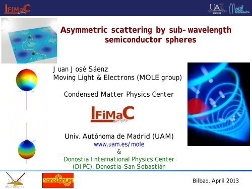
<strong>Asymmetric</strong> <strong>scattering</strong> <strong>by</strong> <strong>sub</strong>-<strong>wavelength</strong><strong>semiconductor</strong> <strong>spheres</strong>Juan José SáenzMoving Light & Electrons (MOLE group)Condensed Matter Physics CenterUniv. Autónoma de Madrid (UAM)www.uam.es/mole&Donostia International Physics Center(DIPC), Donostia-San SebastiánBilbao, April 2013
Braulio García-Cámara, Francisco González,Fernando Moreno(Univ. Cantabria, Santander)Pablo Albella (Material Physics Center CSIC-UPV & DIPC, San Sebastian)Eyraud, C.; Litman, A.; Vaillon, R.;Geffrin, J. M.;Luis S. Froufe-Pérez(Institut Fresnel, Univ. Lyon, CNRS)(IEM-CSIC, Madrid)Manuel Nieto-Vesperinas(ICMM-CSIC, Madrid)Raquel Gómez-Medina, Juan José Sáenz (IFIMAC, UAM-Mole, Madrid)Bilbao, April 2013
➡Magnetic properties of pure dielectric particlesMagnetic Silicon and GermaniumScattering anisotropy➡ Zero backwards and almost zero forwards <strong>scattering</strong>(Forces on dipolar electric and magnetic particles)Bilbao, April 2013
Light <strong>scattering</strong> from spherical particlesThe field scattered <strong>by</strong> the sphere can be decomposedinto a multipole series, (the so-called Mie's expansion),a 1 , b 1 electric and magnetic dipolesa 1 , b 1 electric and magnetic quadrupoles...Fig. 1. Incident field vectora n = 1 2 1 e 2i n= i sin n e i nincident wave is described <strong>by</strong>b n = 1 2 1 e 2i⇥ n= i sin ⇥ n e i⇥ nE = E 0 u Z e ikX e i⌥t , B = B 0 u Y e ikX e i⌥twhere k = m h ⌥/c = m h 2⇧/⇤, ⇤ being the <strong>wavelength</strong> in vacuum and B 0 = µ 0 H(see Fig. 1). The field scattered <strong>by</strong> the sphere can be decomposed into a multiso-called Mie’s expansion), characterized <strong>by</strong> the electric and magnetic Mie cand {b n }, respectively; (a 1 and b 1 being proportional to the electric and magnand b 2 to the quadrupoles, and so on). We shall find useful to write the Mie coefof the <strong>scattering</strong> phase-shifts n and ⇥ n [1]a n = 1 2 1 e 2i ⇥ n= isin n e i nb n = 1 ⇧ ⌃1 e 2i⇥ n= isin⇥ n e i⇥ n2whereBilbao, April 2013tan n = m2 j n (y)[xj n (x)] ⇧ j n (x)[yj n (y)] ⇧m 2 j n (y)[xy n (x)] ⇧ y n (x)[yj n (y)] ⇧ ,
Light <strong>scattering</strong> from VERY SMALL particlesp = ⇥ 0 ⇥ h E E , m = ⇥ 0 ⇥ h M B;E = i✓ k36⇥◆ 1a 1 , M = i✓ k36⇥◆ 1b 1E =(0)E1 i k36(0)E(0)E⇡ 4⇥a 3 m2 1y⌧1 m 2 +2,, M =y ⌘ 2⇥ma/ ⌧ 1(0)M1 i k36(0)M(0)M⇡ 4⇥a 3 (m 2 1) k2 a 2y⌧1 30Nieto-Vesperinas et al., OPEX, 18, 11428 (2010)Bilbao, April 2013
Light <strong>scattering</strong> from VERY SMALL particlesp = ⇥ 0 ⇥ h E E , m = ⇥ 0 ⇥ h M B;E = i✓ k36⇥◆ 1 ✓ ◆ k3 1a 1 , M = i b 16⇥E =(0)E1 i k36(0)E, M =(0)M1 i k36(0)M(0)E⇡ 4⇥a 3 m2 1y⌧1 m 2 +2,(0)M⇡ 4⇥a 3 (m 2 1) k2 a 2y⌧1 30Bilbao, April 2013
Strong magnetic response of <strong>sub</strong>micronSilicon <strong>spheres</strong> in the infraredσ s/a 230252015104.84.44.03.6y3.22.8σ s/a 2σ s(a 1) /a 2σ s(b 1) /a 2σ s(a 2) /a 2σ s(b 2) /a 2Electric dipoleMagnetic dipole501000 1200 1400 1600 1800 2000λ(nm)A. García-Etxarri , R. Gómez-Medina, L. S. Froufe-Pérez, C. López, L. Chantada, F.Scheffold, J. Aizpurua, M. Nieto-Vesperinas and J. J. Sáenz[arXiv:1005.5446 [physics.optics]- 2010] Optics Express 19, 4815 (2011)Fig. 3. Scattering cross-section ⇧ S versus the <strong>wavelength</strong> ⇤ for a 230nm Si sphere (therefraction index m = 3.5 is constant and real in this <strong>wavelength</strong> range). The contribution ofeach term in the Mie expansion is also shown. The green line corresponds to the magneticdipole contribution.Evlyukhin, A., Reinhardt, C., Seidel, A., Luk’yanchuk, B. & Chichkov, B.. Phys. Rev. B 82,045404 (2010).ent regions where the electric dipole contribution is dominating. The remaining blue-saturatedreas are dominated <strong>by</strong> higher order multipoles.In the micrometer <strong>wavelength</strong> regime, within the transparent region of silicon (⇤ 1100m), the index of refraction can well be approximated <strong>by</strong> a real constant m ⇤ ⇧ 12 ⇥ 3.5Bilbao, April 2013
It is interesting to notice that there is no restriction for the magnetic field enhanceman electric dipole to be <strong>sub</strong>stantially large, mainly inside the particle (mid-left plot in FEqually, the electric field enhancement in and around the magnetic dipole can presenvalues (top-center plot in Fig. 4).For a general <strong>wavelength</strong>, different modes contribute to the optical response of the syWe show this effect if the right panel of Fig.y4 for the special case where both the eand magnetic resonances contribute equally to the <strong>scattering</strong> cross section of the Si nano4.8 4.4 4.0 3.6 3.22.8( = 1525nm, cf. Fig. 3). The near field patterns present mixed features of both electrmagnetic30dipoles, and so does the far field with an interesting omnidirectional" s/aSi2 emission pas a result of the sum of both coherent contributions."25s(a 1) /a 2Silicon nanoparticles with radius of the order of 200-250nm are then fully characterizelectric and magnetic polarizabilities (230 as nm) given <strong>by</strong> Eqs. 10 in the mid and" s(bnear-IR 1) /a 2regiotuning the 20appropriate resonance <strong>wavelength</strong>, Si particles exhibit a strong " s(amagnetic 2) /a 2res(only slightly perturbed <strong>by</strong> their electric dipole counterpart)." s(b 2) /a 2It should 15 be remarked that if the relative refractive index is smaller, the overlap bethe Mie resonance lines increases and, as it can be seen in Fig. 2, the first electric resosmeared out 10 for a refraction index lower than m 2.5. Interestingly, the magnetic resonanremains well defined and resolved even for lower index materials. As an example, in Figrepresent the 5 <strong>scattering</strong> cross section of particle with m = ⇥ 6 2.45 which would correto the averaged refractive index of TiO 2 (rutile) in the near IR [31]. For comparison purin order to0cover the same y-range (y = mka) as in Fig. 3, we consider a larger sphereof a = 330nm. 1000 As seen1200 in this figure, 1400 beyond 1400nm 1600the <strong>scattering</strong> 1800is still described 2000!(nm)" s/a 2sent regions20where the electric dipole contribution " s(a 2)/a 2 is dominating. The remaining blue-saturareas are dominated <strong>by</strong> higher order multipoles.In the micrometer <strong>wavelength</strong> regime, within the transparent region of silicon (⇤ 115nm), the index of refraction can well be approximated <strong>by</strong> a real constant m p ⇤ ⇧ 12 ⇥(see for example [31]). The <strong>scattering</strong> (or extinction) cross section of a Si sphere of raa = 230nm in 10vacuum (m h = 1) is plotted in Fig. 3. Although there is a partial overlap betwthe first dipolar peaks, the magnetic line of the first resonant peak (at ⇤ ⇤ 2ma) is still very wresolved. Interestingly, 5 for <strong>wavelength</strong>s larger than ⇤ ⇤ 1200nm, the cross section is compledetermined <strong>by</strong> the first b 1 and a 1 coefficients. In other words, in this regime Si particles catreated as non-Rayleigh 0 dipolar particles.1000 1200 1400 1600 1800 20003. Magnetic and electric resonances of dipolar particlesLet us consider Fig. 5. Scattering further in cross-section some detail ⇥ the <strong>scattering</strong> properties of small dielectric partiS versus the <strong>wavelength</strong> for a sphere of radius a =(x ⌅ 1). 330nm In the(its x ⌅relative 1 limit, refractive the sphere index is ism sufficiently = ⇥ 6 2.45, small constant so that and only real inthe thisdipole <strong>wavelength</strong> scattefields arerange). excited. The The contribution inducedofdipole each coefficient moments, in the proportional Mie expansion to to is also the external shown. The (polariz greenfields, Epeak and B, at longer are usually <strong>wavelength</strong>s writtencorresponds in terms ofto theparticle magneticelectric dipole contribution. and magnetic polarizabilE and M , respectively :whereFig. 3. Scattering cross-section ⇧ S versus the <strong>wavelength</strong> ⇤ for a 230nm Si sphere (therefraction index m = 3.5 is constant and real in this y <strong>wavelength</strong> range). The contribution ofeach term in4.8the Mie4.4expansion 4.0is also shown. 3.6 The green 3.230line corresponds 2.8to the magneticdipole contribution." s /a 225" s (a 1 )/a TiO 2" s (b 1 )/a22(150 nm)" s (b 2 )/a 2" s/a 2! (nm)Bilbao, April 2013p = ⇥ 0 ⇥ h E E , m = ⇥ 0 ⇥ h M B;
Forces and Scattering anisotropynce of absorption,(0)e and m(0)are real quantities.ure electric or a pure magnetic dipole, in absence of interferences, the fFor a pure electric or a pure magnetic dipole,the far field radiation pattern is symmetrically distributed betweenforward and backward <strong>scattering</strong>.n pattern is symmetrically distributed between forward and backward swever, when we consider the coherent contribution of both electric and mFor coherent electric and magnetic dipoles (Huygens sources)the radiation pattern is mainly distributed in the forward orbackward region according to whether R(αeα ∗ m ) is positive ornegative., the radiation pattern is mainly distributed in the forward or backward⇥ng to whether ⌅( e m )ispositiveornegative,respectively[33,34].Intereso-called Kerker conditions, |⇥ 1 e| 2 = |µ m | 2 , the scattered intensity shodent of the incident polarization angle:dQ Sd(⇤) =k 4 ⇤ ⇤ ⇥1e⇤ ⇤21+cos 2 ⇤ ⇥ +2k 4 µ ⇥ ⌅( e⇥m)cos⇤.terference between electric and magnetic dipoles lead to a number of inteintensity in the back<strong>scattering</strong> direction can be exactly zero wheneverBilbao, April 2013
Forces and Scattering anisotropyR. Gómez-Medina et al. J. Nanophoton. (2011)Bilbao, April 2013
we atconsider the so-called the coherent Kerkercontribution conditions, of |⇥ both e| electric = |µ m and | , magnetic the scattered intensity should benindependent pattern Forces is and mainly of Scattering thedistributed incident anisotropy polarization in the forward angle: or backward region⇥r ⌅( e m )ispositiveornegative,respectively[33,34].Interestingly,dQNieto-Vesperinas, Gómez-Medina Sand Sáenzker conditions, |⇥JOSA A (2011)1 e| (⇤) 2 = =k ⇤ ⇤|µ 4 m ⇥ | 2 1, the e 2scattered 1+cos 2 intensity ⇤ ⇥ +2k 4 µ dshould⇥ ⌅( ⇥e be m)cos⇤. (9)ncident polarization angle:The interference between electric and magnetic dipoles lead to a number of interesting⇤) The =k 4 interference ⇤ ⇤e⇥ects:⇥1e 21+cos between 2 ⇤ ⇥ +2k 4 electric µ and magnetic dipoles lead to anumber of interesting effects: ⇥ ⌅( ⇥e m)cos⇤. (9)ween i) The electric intensity and magnetic in the back<strong>scattering</strong> dipoles lead direction to a number can of beinterestingexactly zero wheneveri) The intensity in the back<strong>scattering</strong> direction can be exactly zerowhenever⇥ 1 dQ Se = µ m ;dThis (180anomaly ⇤ )=0.corresponds to the socalledfirst Kerker condition,(10)he back<strong>scattering</strong> direction can be exactly zero wheneverThis anomaly corresponds to the so-called first Kerker condition [24], theoretically predictedfor e = magnetodielectric µ m ; (180particles ⇤ )=0. having (10)⇥ 1 dQ Stheoretically predicted fordmagnetodielectric ⇥ p = µ p .particles having ε = µponds ii) Although to the so-called the intensity first Kerker can not condition be exactly [24], theoretically zero in preielectricimposes ii) In absence particles ⇧{ e }, having of ⇧{ particle m } ⇥ p = > µ 0), absorption, p . in absencethe of forward particle absorption, intensity presents the forward a intensityforward direction (causalityminimum atensitypresentscananotminimumbe exactlyat [34]zero in the forward direction (causalitym} > 0), in absence⌅{⇥of 1 particle absorption, the forward intensitye} = ⌅{µ m } and ⇧{⇥ 1 e} = ⇧{µ m }at [34]dQ S(0 ⇤ 16) =⇤ 1e } = ⌅{µ m } and ⇧{⇥d 1 e} = ⇧{µ m }9 k10 ⇤⇥ 1 ⇤ 4 e(11)19dQ S(0 ⇤ 16) =⇤ For lossless magnetodielectricd9 k10 Rayleigh ⇤⇥ 1 ⇤ 4 e particles, this happens (11) when [24,35] ⇥ p = (µ pBilbao, April 20134)/(2µ p +1) and it is known as the second Kerker condition. Although the original
ipolar resonance (at ⌅ ⇥ 1500nm) are still very well defined.Forces and Scattering anisotropyAs we will see, thisverlap plays a key role in determining the peculiar <strong>scattering</strong> diagrams of Ge particles.nterestingly, for <strong>wavelength</strong>s larger than ⌅ ⇥ 1400nm the cross section is completelyetermined <strong>by</strong> the first b 1 and a 1 coe cients. In other words, in this regime Ge particlesan be treated as dipolar particles.Q ext121086420Ge (a=240 nm)Q exttotalQ ext (a 1 )Q ext (b 1 )Q ext (a 2 )Q ext (b 2 )1,2 1,4 1,6 1,8 2,0 2,2 2,4λ (µm )igure 1: Extintion cross-section Q ext versus the <strong>wavelength</strong> ⌅ for a 240nm Ge sphere (theefraction index m p =4isconstantandrealinthis<strong>wavelength</strong>range). Thecontributionf each term in the Mie expansion is also shown. The red line corresponds to the magneticvertical lines, respectively.R. Gómez-Medina et al., J. Nanophoton. (2011)ipole contribution.Figure 2: Normalized real and imaginary parts of both the electric and maizabilities for a Ge sphere of radius a =240nm; p =16andµ p =1. Thehas = µ =1. ThefirstandsecondKerkerconditionsaremarked<strong>by</strong>theipolar particles are usually characterized <strong>by</strong> their electric and/or magnetic complexolarizabilities, e and m which may be written in the form [33, 37]In order to check the validity of the dipolarBilbao,approachApriland confirm2013thethe Kerker condition, we have computed the exact <strong>scattering</strong> diagram from
J.M. Geffrin et al.,Nature Commun. (2012) MicrowavesBilbao, April 2013
Visible (GaAs) => S. Person, M. Jain, Z. Lapin, JJ Sáenz, GWicks, & L. Novotny, Nanoletters (2013)See also:Visible (Si) => Y. Fu, A.I. Kuznetsov, A.E. Miroshnichenko, Y. F. Yu& B. Luk’yanchuk, Nature Commun. (2013)Bilbao, April 2013
tuning the appropriate resonance <strong>wavelength</strong>, Si particles exhibit a strong magnetic response,(only slightly perturbed <strong>by</strong> their electric dipole counterpart).It should be remarked that if the relative refractive index is smaller, the overlap betweenthe Mie resonance lines increases and, as it can be seen in Fig. 2, the first electric resonancesmeared out for a refraction index lower than m 2.5. Interestingly, the magnetic resonance lineremains well defined and resolved even for lower index materials. As an example, in Fig. 5 werepresent the <strong>scattering</strong> cross section of particle with m = ⇥ 6 2.45 which would correspondto the averaged refractive index of TiO 2 (rutile) in the near IR [31]. For comparison purposes,in order to cover the same y-range (y = mka) as in Fig. 3, we consider a larger sphere radiusof a = 330nm. As seen in this figure, beyond 1400nm the <strong>scattering</strong> is still described <strong>by</strong> the" s/a 2302520154.84.44.0y3.6 3.22.8" s /a 2" s (a 1 )/a 2" s (b 1 )/a 2" s(a 2)/a 2" s (b 2 )/a 2TiO 2(150 nm)10501000 1200 1400 1600 1800 2000! (nm)Fig. 5. Scattering cross-section ⇥ S versus the <strong>wavelength</strong> for a sphere of radius a =330nm (its relative refractive index is m = ⇥ 6 2.45, constant and real in this <strong>wavelength</strong>range). The contribution of each coefficient in the Mie expansion is also shown. The greenpeak at longer <strong>wavelength</strong>s corresponds to the magnetic dipole contribution.Y. Zhang, R. Gómez-Medina,M. Nieto Vesperinas & J.J. SáenzPoster-PPM/Imaginenano 2013Bilbao, April 2013
Scattering asymmetry:--- Directivity of optical antennas- A. Krasnok, A. Miroshnichenko, P. Belov, and Y. Kivshar, JETP Lett. (2011).- W. Liu, A.E. Miroshnichenko, D. N. Neshev & Y.S. Kivshar, ACS Nano (2012)- B. Rolly, B. Stout & N. Bonod, OPEX (2012), Opt. Lett. (2011)- . . .--- Optical forces on small <strong>semiconductor</strong> particles--- Transport mean free path disordered dispersion of lossless<strong>semiconductor</strong> nano<strong>spheres</strong>Bilbao, April 2013
Bilbao, April 2013
Bilbao, April 2013
Tailoring the properties ofthe object.a) Ordinary optical elements, such aslenses and prisms, can be designed toenhance the forwards <strong>scattering</strong> suchthat the electromagnetic momentum ofthe incident beam is less than that ofthe emergent beam.Dogariu, Shukov & SáenzNature Photon. (2013)b, Analogously, small <strong>sub</strong><strong>wavelength</strong>particles can be designed to scatterstrongly forwards in such a way that theoverall optical force points in a directionopposite to that of the incident beam.Bilbao, April 2013
Submicrometre <strong>semiconductor</strong> <strong>spheres</strong> (Silicon, Germanium) arecapable of exhibiting dipolar magnetic and electric responses.Interference between the electric and magnetic dipolar fields canlead to anisotropic <strong>scattering</strong> includingzero backwards and almost-zero forwards <strong>scattering</strong>at specific <strong>wavelength</strong>s(non-conventional <strong>scattering</strong> properties similar to those previouslyreported for somewhat hypothetical magnetodielectric particles)Bilbao, April 2013
Semiconductor nano<strong>spheres</strong> as opticalpulling probes inlaser tractor beams.Bilbao, April 2013
Silvia Albaladejo, Irene Suárez-LacalleRaquel Gómez-Medina, Miztli Yépez, Yan Zhang, Juraj Feilhauer,Manuel I. Marqués, Juanjo Sáenz * (IFIMAC, UAM-Mole, Madrid)Luis S. Froufe-Pérez(IEM-CSIC, Madrid)Manuel Nieto-Vesperinas(ICMM-CSIC, Madrid)Braulio García-Cámara, Francisco González,Fernando Moreno(Univ. Cantabria, Santander)Pablo Abella, Mikolaj K. Schmid, Rubén Esteban,Javier Aizpurua(DIPC, San Sebastian)Cefe López(ICMM-CSIC, Madrid)Ignacio Iglesias(Univ. Murcia)Frank Scheffold(Fribourg Univ., Switzerland)Sergey Sukhov, Aristide Dogariu (CREOL, Florida, USA)Geffrin, J. M.; Eyraud, C.; Litman,A.; Vaillon, R.;(Institut Fresnel, Univ. Lyon, CNRS)S. Person,M. Jain, Z.Lapin, G. Wicks,Lukas Novotny (ETH, Zürich, Switzerland)Bilbao, April 2013