SINAMICS S120 Servo Control Drive System
SINAMICS S120 Servo Control Drive System
SINAMICS S120 Servo Control Drive System
- No tags were found...

You also want an ePaper? Increase the reach of your titles
YUMPU automatically turns print PDFs into web optimized ePapers that Google loves.
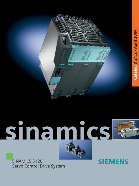
Catalog D 21.2 • April 2004sinamics<strong>SINAMICS</strong> <strong>S120</strong><strong>Servo</strong> <strong>Control</strong> <strong>Drive</strong> <strong>System</strong>
<strong>SINAMICS</strong> <strong>S120</strong><strong>Servo</strong> <strong>Control</strong><strong>Drive</strong> <strong>System</strong>IntroductionWelcome toAutomation and <strong>Drive</strong>sTotally IntegratedAutomation<strong>System</strong> overview<strong>SINAMICS</strong>1Catalog D 21.2April 2004The products described in this catalogalso appear inCD-ROM catalog CA 01Order No.:E86060-D4001-A110-C2-7600For details, please contact yourSiemens representative.<strong>Drive</strong> systemMotors<strong>SINAMICS</strong> <strong>S120</strong>AC motorsLine-side powercomponentsLine/Motor ModulesDC link components<strong>Control</strong> UnitsSupplementary componentsEncoder system connection2Synchronous motorsAsynchronous motorsGear unitsSelection guide 3© Siemens AG 2004The products and systemsdescribed in thiscatalog are distributed inaccordance with the requirementsof a qualitymanagement systemwhich has been certifiedto DIN EN ISO 9001(Certificate RegistrationNo. 001258 QM) andDIN EN ISO 14001(Certificate RegistrationNo. 081342 UM). Thecertificates arerecognized in all IQNetcountries.sAdditional information Additional componentsMeasuring systems SIMODRIVE sensorsBuilt-on rotary encodersConnectionsystemEngineeringinformationServices anddocumentationAppendix4MOTION-CONNECTDRIVE-CLiQPower cablesSignal cables 5Selection guidesPlanningDimensioningOrdering example 6ApplicationsTrainingTraining packageService & SupportDocumentationGlossaryA&D online servicesIndex of order numbersSubject indexConditions ofsale and deliveryExport regulations78
Welcome toAutomation and <strong>Drive</strong>sWe would like to welcome you to Automation and<strong>Drive</strong>s and our comprehensive range of products,systems, solutions and services for production andprocess automation and buildingtechnologyworldwide.With Totally Integrated Automation and TotallyIntegrated Power, we deliver solution platforms basedon standards that offer you a considerable savingspotential.Discover the world of our technology now. If you needmore detailed information, please contact one of yourregional Siemens partners.They will be glad to assist you.1/2 Siemens D 21.2 · April 2004
Siemens D 21.2 · April 20041/3
EthernetTotally Integrated Automation –innovations for more productivityWith the launch of Totally Integrated Automation, we werethe first ones on the market to consistently implement thetrend from equipment to an integrated automation solution,and have continuously improved the system ever since.Whether your industry is process- and production-oriented ora hybrid, Totally Integrated Automation is a unique "commonsolution" platform that covers all the sectors.Totally Integrated Automation is an integrated platform for theentire production line - from receivingto technical processingERPEnterpriseResourcePlanningEthernetMESManufacturingExecution<strong>System</strong>sEthernetProductionOrderManagementProductionOperationsRecordingMaterialManagementEquipmentManagement<strong>Control</strong>SIMATIC NETIndustrialCommunicationSINAUT Telecontrol<strong>System</strong>SIMATICSoftwareSIMATICMachine VisionIndustrialIndustrialEthernetSafety IntegratedIndustrial WirelessCommunication/MOBICPROCESS FIELDPROFIBUSPC-based AutomationAS-InterfaceGAMMA instabusBuildingTechnologyMicro-AutomationandActuator-SensorInterface LevelECOFAST IP65DecentralAutomation <strong>System</strong>1/4Siemens D 21.2 · April 2004
and production areas to shipping. Thanks to the system-orientedengineering environment, integrated, open communicationsas well as intelligent diagnostics options, your plant nowbenefits in every phase of the life cycle.In fact, to this day we are the only company worldwide thatcan offer a control system based on an integrated platformfor both the production and process industry.SIMATIC IT FrameworkProduction ModelerPlantInformationManagementDetailedProductionSchedulingProduct SpecificationManagement <strong>System</strong>Laboratory InformationManagement <strong>System</strong>SIMATIC<strong>Control</strong>ler/Automation<strong>System</strong>SINUMERIKNumeric<strong>Control</strong>SIMOTIONMotion <strong>Control</strong><strong>System</strong>SIMATIC HMIHuman MachineInterfaceSENTRONCircuitBreakersSIMATICDistributedI/OSIMATIC PCS 7Process <strong>Control</strong><strong>System</strong>Field Instrumentation/AnalyticsSIMOCODE-DPMotorProtectionand <strong>Control</strong>SensorTechnologyIQ-SenseHARTPROFIBUSPASIMODRIVE<strong>SINAMICS</strong><strong>Drive</strong> <strong>System</strong>s/<strong>SINAMICS</strong>Siemens D 21.2 · April 20041/5
1Introduction<strong>SINAMICS</strong> drives family<strong>SINAMICS</strong> G<strong>SINAMICS</strong> SExtrusionForming/ShapingPumps/FansPackagingPrinting MachinesTextilesConveyor <strong>System</strong>sRolling MillsMachine ToolsG_D212_EN_00053<strong>SINAMICS</strong> applicationsApplications<strong>SINAMICS</strong> is the new drives family from Siemens designed formachine building and plant engineering applications.<strong>SINAMICS</strong> offers solutions for all drive tasks:7 Simple pump and fan applications in the process industry7 Demanding single drives in centrifuges, presses, extruders,elevators, as well as conveyor and transport systems7 <strong>Drive</strong> line-ups in textile, plastic film and paper machines, aswell as in rolling mill plants7 Highly dynamic servo drives for machine tools, as well as packagingand printing machinesProduct variantsDepending on the application, the <strong>SINAMICS</strong> range offers theideal version for any drive task.7 <strong>SINAMICS</strong> G is designed for standard applications with asynchronousmotors. These applications have less stringent requirementsregarding the dynamics and accuracy of the motorspeed.7 <strong>SINAMICS</strong> S handles demanding drive tasks with synchronous/asynchronousmotors and fulfills stringent requirementsregarding:- Dynamics and accuracy- Integration of extensive technological functions in the drivecontrol systemPlatform Concept and Totally Integrated AutomationAll <strong>SINAMICS</strong> variants are based on a platform concept. Commonhardware and software components, as well as standardizedtools for design, configuration, and commissioning tasksensure high-level integration across all components. <strong>SINAMICS</strong>handles a wide variety of drive tasks without system breaks. Thedifferent <strong>SINAMICS</strong> variants can be easily combined with eachother.<strong>SINAMICS</strong> is a part of the Siemens "Totally Integrated Automation"concept. Integrated <strong>SINAMICS</strong> systems covering configuration,data management and communication at the automationlevel ensure low-maintenance solutions with SIMATIC andSIMOTION.1/6 Siemens D 21.2 · April 2004
Introduction<strong>SINAMICS</strong> drives family1<strong>SINAMICS</strong> as part of the Siemens modular automation systemQuality to DIN EN ISO 9001<strong>SINAMICS</strong> is able to meet the highest requirements in terms ofquality. Extensive quality assurance in product design as well asin all development and production processes ensures a constantlyhigh level of quality.Our quality assurance system has of course been certified by anindependent body in accordance with DIN EN ISO 9001.Suitable for use anywhere in the world<strong>SINAMICS</strong> meets the requirements of relevant international standardsand regulations –a from the EN European standardsthrough IEC to UL and cULus.Siemens D 21.2 · April 20041/7
1Introduction<strong>SINAMICS</strong> <strong>S120</strong> servo control drive systemDC 24 Va <strong>Control</strong> UnitPower Supplys Smart Lineor ActiveLine Moduled SingleMotor ModuleTerminal ModulesOption Boardsa s d f gf DoubleMotor Moduleg SingleMotor ModuleData linePC ToolsSIZERSTARTERIncoming power3 AC 380 V to 480 VSensorModuleLine reactorLine filterPower line MOTION-CONNECTSignal line MOTION-CONNECTDRIVE-CLiQDRIVE-CLiQ MOTION-CONNECTAsynchronous motorwith DRIVE-CLiQinterfaceSynchronousmotors withDRIVE-CLiQinterfaceSynchronous motorwithout DRIVE-CLiQinterfaceG_D212_EN_00055<strong>SINAMICS</strong> <strong>S120</strong> system overview1/8 Siemens D 21.2 · April 2004
Modular system for demanding drive tasks<strong>SINAMICS</strong> <strong>S120</strong> solves demanding drive tasks for a wide rangeof industrial applications and is, therefore, designed as a modularsystem. Users can choose from many different harmonizedcomponents and functions to create a solution that best meetstheir requirements. SIZER, a high-performance configurationtool, makes it easier to choose and determine the optimum driveconfiguration.<strong>SINAMICS</strong> <strong>S120</strong> is enhanced by a wide range of motors. Whethersynchronous or asynchronous, all motor types are supportedby <strong>SINAMICS</strong> <strong>S120</strong>.<strong>Drive</strong> for multi-axis applicationsThe trend towards separate axes in machine building is growingall the time. Where possible, central drives are being replacedby electronically coordinated servo drives. <strong>Drive</strong>s with coupledDC links are required for this purpose, as they support economicenergy exchange between braking and driving axes.<strong>SINAMICS</strong> <strong>S120</strong> boasts line supplies and inverter modules coveringa wide power range, which, having been designed forseamless integration, pave the way for compact multi-axis driveconfigurations.New system architecture with a central control unitElectronically coordinated individual drives work together to performyour drive tasks. Higher-level controllers operate the drivesto achieve the required coordinated movement. This requires cyclicdata exchange between the controller and all the drives.This exchange usually took place via a field bus, which requireda great deal of time and effort for installation and configuration.<strong>SINAMICS</strong> <strong>S120</strong> takes a different approach. A central controlunit controls the drives for all connected axes and also establishesthe technological links between the drives and/or axes.Since all the required data is stored in the central control unit, itdoes not need to be transferred. Inter-axis connections can beestablished within a control unit and easily configured in theSTARTER commissioning tool.Simple technological tasks can be carried out automatically bythe <strong>SINAMICS</strong> <strong>S120</strong> control unit. For complex numerical or motion-controltasks, high-performance SIMOTION D modules areused instead.DRIVE-CLiQ – the digital interface between all componentsAll <strong>SINAMICS</strong> <strong>S120</strong> components, including the motors and encoders,are interconnected via a joint serial interface calledDRIVE-CLiQ. The standardized cables and connectors reducethe variety of different parts and cut inventory costs.Converter boards (sensor modules) for converting standard encodersignals to DRIVE-CLiQ are available for third-party motorsor retrofit applications.Introduction<strong>SINAMICS</strong> <strong>S120</strong> servo control drive system1Siemens D 21.2 · April 20041/9
1Introduction<strong>SINAMICS</strong> <strong>S120</strong> servo control drive systemElectronic rating plate in all componentsDC 24 Va <strong>Control</strong> UnitPower supplys Smart Lineor ActiveLine Moduled SingleMotor ModuleTerminal ModulesOption Boardsa s d f gf DoubleMotor Moduleg SingleMotor ModuleData linePC ToolsSIZERSTARTERIncoming power3 AC 380 V to 480 VSensorModuleLine reactorLine filterAsynchronous motorwith DRIVE-CLiQinterfaceSynchronousmotors withDRIVE-CLiQinterfaceSynchronous motorwithout DRIVE-CLiQinterfaceG_D212_EN_00056Detection of electronic rating plates via DRIVE-CLiQ with <strong>SINAMICS</strong> <strong>S120</strong>All <strong>SINAMICS</strong> <strong>S120</strong> components have an electronic rating platethat contains all the relevant data about that particular component.In the motors, for example, this data includes the parametersof the electric equivalent circuit diagram and characteristicvalues for the built-in motor encoder. The control unit records thisdata automatically via DRIVE-CLiQ so that it does not need to beentered during commissioning or when the equipment is replaced.In addition to the technical data, the rating plate includes logisticaldata (manufacturer ID, order number, and globally uniqueID). Since this data can be called up electronically on siteor remotely, all the components used in a machine can alwaysbe individually identified, which helps simplify servicing.1/10 Siemens D 21.2 · April 2004
<strong>SINAMICS</strong> <strong>S120</strong> drive system componentsIntroduction<strong>SINAMICS</strong> <strong>S120</strong> servo control drive system1Connectors3 AC LineLine-side power componentsLine contactorsLine fusesLine filtersLine reactorsPower supplies<strong>SINAMICS</strong> <strong>S120</strong> componentsLine ModulesSmart Line ModulesActive Line Modules<strong>Control</strong> UnitsSIMOTIONDC link componentsBraking Moduleswith braking resistorsCapacitor Modules<strong>Control</strong> Supply ModulesAdditional systems componentsund Sensor ModulesOption BoardsTerminal ModulesSensor ModulesMotor ModulesSingle Motor ModulesDouble Motor ModulesMotorsAsynchron motorsSynchronous motorsG_D212_EN_00057Siemens D 21.2 · April 20041/11
1NotesIntroductionThe overview on page 1/11 features the <strong>SINAMICS</strong> <strong>S120</strong> componentsthat are primarily used for multi-axis drive tasks.The following power components are available:7 Line-side power components such as fuses, contactors, reactors,and filters for switching the power supply and meetingEMC requirements.7 Line modules, which supply power centrally to the DC link.7 DC link components, which can be used as options to stabilizethe DC link voltage and/or to buffer the electronics powersupply.7 Motor modules, which act as inverters, receive power fromthe DC link, and buffer the connected motors.The <strong>SINAMICS</strong> <strong>S120</strong> components have been developed for installationin cabinets. They have the following features and characteristics:• Easy to handle, simple installation and wiring• Practical connection system, cable routing in accordance withEMC requirements• Standardized design, seamless integration• Internal cooling-fans (other cooling methods available on request)To carry out the required functions, <strong>SINAMICS</strong> <strong>S120</strong> is equippedwith:7 A control unit that carries out all drive and technological functionsacross all axes.7 Additional system components that enhance functionalityand offer different interfaces for encoders and process signals.1/12 Siemens D 21.2 · April 2004
<strong>SINAMICS</strong> <strong>S120</strong> <strong>Servo</strong>2/2 <strong>System</strong> data2/2 General technical data2/3 Overload capability2/4 Derating characteristics2/5 Line-sidepower components2/5 Line filters2/7 Line reactors2/9 Assignment overview2/10 Line Modules2/10 Smart Line Modules2/13 Active Line Modules2/16 Motor Modules2/16 Single Motor Modules2/21 Double Motor Modules2/24 DC link components2/24 Braking Module2/26 Brake resistors2/27 Capacitor Module2/28 <strong>Control</strong> Supply Module2/29 DC link power supply adapter2/30 <strong>Control</strong> units2/30 CU320 <strong>Control</strong> Unit2/33 CompactFlash Card2/34 Supplementary systemcomponents2/34 CBC10 Communication Board2/35 TB30 Terminal Board2/37 TM31 Terminal Module2/39 Sensor system connection2/40 SMC10 Sensor Module Cabinetmounted2/41 SMC20 Sensor Module Cabinetmounted2/42 SMC30 Sensor Module CabinetmountedSiemens D 21.2 · April 2004
2<strong>SINAMICS</strong> <strong>S120</strong> <strong>Servo</strong><strong>System</strong> dataGeneral technical data■ Technical dataUnless explicitly specified otherwise, the following technicaldata are valid for all components of the <strong>SINAMICS</strong> <strong>S120</strong> drivesystem described here.Electrical dataLine connection voltage 3 AC 380 V to 480 V ±10%(-15% < 1 min)Line frequency 50/60 Hz, -6/+6%Electronic power supply DC 24 V, -15/+20%Radio interference suppression•StandardNo radio interference suppression•With line filterClass A1 to EN 55 011 possibleOvervoltage category Class III to EN 60 664-1Mechanical dataVibration stressing•TransportEN 60 721-3-2, Class 2M3•OperationEN 60 721-3-3, Class 3M4Shock stressing•TransportEN 60 721-3-2, Class 2M3•OperationEN 60 721-3-3, Class 3M4Ambient conditionsDegree of protection IP20 to EN 60 529Protection classClass I (with protective conductorsystem) and Class III (PELV) toEN 61 800-5-1Cooling methodInternal ventilation, power sectionswith forced air cooling with integratedcooling fanAmbient conditionsPermissible ambient and coolanttemperature (air) during operationfor line-side components, LineModules and Motor ModulesPermissible ambient and coolanttemperature (air) during operationfor control units, additional systemcomponents, DC link componentsand Sensor ModulesClimatic ambientconditions0 °C (+32 °F) to +40 °C (+104 °F)without derating,> +40 °C (+104 °F) to +55 °C(+131 °F) see derating characteristics0 °C (+32 °F) to +55 °C (+131 °F)•Storage Class 1K3 to EN 60 721-3-1Temperature -25 °C (-13 °F) to+55 °C (+131 °F)•Transport Class 2K4 to EN 60 721-3-2Temperature -40 °C (-40 °F) to+70 °C (+158 °F)Max. humidity 95% at +40 °C(+104 °F)•Operation Class 3K3 to EN 60 721-3-3Relative humidity 5 to 65% annualaverage,≤ 80% max. 2 months per year,condensation, splashwater andice formation not permitted(EN 60 204, Part 1)Environmental class/harmfulchemical substances•Storage Class 1C2 to EN 60 721-3-1•Transport Class 2C2 to EN 60 721-3-2•Operation Class 3C2 to EN 60 721-3-3Organic/biological influences•Storage Class 1B1 to EN 60 721-3-1•Transport Class 2B1 to EN 60 721-3-2•Operation Class 3B1 to EN 60 721-3-3Degree of pollution 2 to EN 60 664-1Installation altitudeUp to 1000 m (3282 ft) above sealevelno derating,> 1000 m (3282 ft) to 5000 m(16,408 ft) above sea level seederating characteristicsApprovalsCertificationCE (low-voltage and EMC Directives),cULus (file nos.: E192450,E164110 and E70122)Safety Integrated – safe standstill(SH) and safe brake control (SBC)ModulesLine Modulesin Booksize format•Rated supply voltageActive Line Modules inBooksize format•Rated pulse frequencyMotor Modulesin Booksize format•DC link connection voltage•Rated pulse frequencySafety Integrity Level (SIL) 2 toIEC 61508, control category 3 toEN 954-13 AC 380 V to 480 V8kHzDC 510 V to 750 V4kHz2/2 Siemens D 21.2 · April 2004
■ Technical data (continued)Overload capabilityLine Modules in Booksize formatPPmax<strong>SINAMICS</strong> <strong>S120</strong> <strong>Servo</strong><strong>System</strong> dataMotor Modules in Booksize formatI maxIGeneral technical data2Prated0.2 s10 stG_D212_en_00063I rated0.25 s10 stG_D212_en_00065Load cycle with preloadingLoad cycle with preloadingPIPmaxI maxPS6I S6P rated0.4 x Prated4 min10 mintG_D212_en_00061I rated0.7 x I rated4 min10 mintG_D212_en_00067S6 load cycle with preloadingS6 load cycle with preloadingP maxPI maxIP rated0.4 x Prated10 s60 stG_D212_en_00062aI rated0.7 x I rated10 s60 stG_D212_en_00068S6 load cycle with preloadingS6 load cycle with preloadingmaxrated2.65 s10 stG_D212_en_00066Load cycle without preloadingSiemens D 21.2 · April 20042/3
<strong>SINAMICS</strong> <strong>S120</strong> <strong>Servo</strong><strong>System</strong> dataDerating characteristics2■ CharacteristicsDerating characteristics for Line Modules in Booksize formatPermissible output power100%908070605530 35 40 45 50 °C 55(86) (95) (104) (113) (122) (°F) (131)Ambient temperatureG_D212_EN_00058aDerating characteristics for Motor Modules in BooksizeformatPermissible output current100%908070605530 35 40 45 50 °C 55(86) (95) (104) (113) (122) (°F) (131)Ambient temperatureG_D212_EN_00001aRated output power as a function of ambient temperatureRated output current as a function of ambient temperaturePermissible output power100%9080706050403020100 2 4 6 8 10 12 14 16 kHz 20Pulse frequencyG_D212_EN_00059Permissible output current100%9080706050403020100 2 4 6 8 10 12 14 16 kHz 20Pulse frequencyG_D212_EN_00002aRated output power as a function of pulse frequency (Active Line Modules only)Rated output current as a function of pulse frequencyPermissible output power100%9590858075706560550 1000 2000 3000 4000 m 5000(3282) (6563) (9845) (13126) (ft) (16408)Installation altitude above sea levelG_D212_EN_00060Permissible output current100%9590858075706560550 1000 2000 3000 4000 m 5000(3282) (6563) (9845) (13126) (ft) (16408)Installation altitude above sea levelG_D212_EN_00003aRated output power as a function of installation altitudeCorrection factors for increased ambient temperatures andinstallation altitudesIf the Line and Motor Modules are operated at ambient temperaturesof > 40°C (104°F) and installation altitudes of > 1000 m(3282 ft), both derating characteristics must be taken into accountfor the permissible output power/output current.Rated output current as a function of installation altitudeExample:A motor module is to operate at an ambient temperature of 55°C(131°F) (60% permissible output current) and an installationaltitude of 3000 m (9845 ft) (75% permissible output current).The permissible output current in this case is100 x (0.60 x 0.75) = 45%.2/4 Siemens D 21.2 · April 2004
■ OverviewLine-side power components are used to protect the connectedcomponents against transient or continuous overvoltages andensure that prescribed limit values are adhered to.<strong>SINAMICS</strong> <strong>S120</strong> <strong>Servo</strong>Line-side power componentsLine filters■ Selection and ordering dataLine filters can only be ordered together with the appropriate linereactor. The order number comprises the line filter and the linereactor.Line filters andline reactors5 kW(6.5 HP)10 kW(13.5 HP)For Smart Line Modules Order No.Line filters and line reactors6SL3130-6AE15-0AA06SL3130-6AE21-0AA06SL3000-0GE15-0AA06SL3000-0GE21-0AA02Line filters andline reactors16 kW(21.5 HP)36 kW(48 HP)55 kW(74 HP)80 kW(107 HP)120 kW(160 HP)For Active Line Modules Order No.Line filters and line reactors6SL3130-7TE21-6AA16SL3130-7TE23-6AA16SL3130-7TE25-5AA16SL3130-7TE28-0AA06SL3130-7TE31-2AA06SL3000-0FE21-6AA06SL3000-0FE23-6AA06SL3000-0FE25-5AA06SL3000-0FE28-0AA06SL3000-0FE31-2AA1When combined with line reactors and a consistent systemstructure, line filters limit the conducted interference emitted bythe power modules to permissible values for industrial supplies(Class A1 to EN 61 800-3) at the installation site. Line filters areonly suitable for direct connection to TN systems (grounded).■ AccessoriesAdapter sets are available for very compact installation. Theyenable line filters and line reactors to be installed compactly oneabove the other in the control cabinet.Adapter set for line filterand line reactorActive LineModule poweroutputOrder No.Adapter set6SL3000-0FE21-6AA0 16 kW (21.5 HP) 6SL3060-1FE21-6AA06SL3000-0FE23-6AA0 36 kW (48 HP) 6SN1162-0GA00-0CA0Siemens D 21.2 · April 20042/5
<strong>SINAMICS</strong> <strong>S120</strong> <strong>Servo</strong>Line-side power componentsLine filters2■ Technical dataForSmart LineModuleRated powerinfeed of theSmart LineModuleLine filtersType 6SL3130-6AE15-0AA0 6SL3130-6AE21-0AA0kW(HP)5(6.5)10(13.5)Rated current A 12 24Power loss kW 0.005 0.009Line/power connectionL1, L2, L3 / U, V, WPE connectionWidthHeightDepthWeight,approx.mm(inch)mm(inch)mm(inch)kg(lb)Screw-type terminals Screw-type terminals10 mm 2 10 mm 2On housingwith M6 bolt60(2.36)285(11.22)122(4.8)2.0(4.4)On housingwith M6 bolt60(2.36)285(11.22)122(4.8)2.4(5.3)ForActive LineModuleRated powerinfeed of theActive LineModuleLine filtersType 6SL3130-7TE21-6AA1 6SL3130-7TE23-6AA1 6SL3130-7TE25-5AA1 6SL3130-7TE28-0AA0 6SL3130-7TE31-2AA0kW(HP)16(21.5)36(48)Rated current A 30 67 103 150 225Power loss kW 0.17 0.25 0.35 0.45 0.59Line/power connectionL1, L2, L3 / U, V, WPE connectionWidthHeightDepthWeight,approx.mm(inch)mm(inch)mm(inch)kg(lb)55(74)80(107)120(160)Screw-type terminals Screw-type terminals Screw-type terminals Screw-type terminals M10 connecting lugs10 mm 2 50 mm 2 50 mm 2 95 mm 2On housingwith M5 bolt130(5.12)480(18.9)150(5.9)9(19.8)On housingwith M8 bolt130(5.12)480(18.9)245(9.65)16(35.3)On housingwith M8 bolt130(5.12)480(18.9)260(10.24)19(41.9)On housingwith M8 bolt200(7.87)480(18.9)260(10.24)22(48.5)On housingwith M8 bolt300(11.81)480(18.9)260(10.24)32(70.6)2/6 Siemens D 21.2 · April 2004
<strong>SINAMICS</strong> <strong>S120</strong> <strong>Servo</strong>Line-side power componentsLine reactors■ Overview■ Selection and ordering dataLine reactor5 kW(6.5 HP)10 kW(13.5 HP)For Smart Line Modules Order No.Line reactor6SL3130-6AE15-0AA06SL3130-6AE21-0AA06SL3000-0CE15-0AA06SL3000-0CE21-0AA02Line reactor16 kW(21.5 HP)36 kW(48 HP)55 kW(74 HP)80 kW(107 HP)120 kW(160 HP)For Active Line Modules Order No.Line reactor6SL3130-7TE21-6AA16SL3130-7TE23-6AA16SL3130-7TE25-5AA16SL3130-7TE28-0AA06SL3130-7TE31-2AA06SN1111-0AA00-0BA16SN1111-0AA00-0CA16SN1111-0AA00-0DA16SN1111-0AA00-1EA06SL3000-0DE31-2BA0Line reactors limit low-frequency line harmonics to permissiblevalues. For this reason, line reactors must always be used.Siemens D 21.2 · April 20042/7
<strong>SINAMICS</strong> <strong>S120</strong> <strong>Servo</strong>Line-side power componentsLine reactors2■ Technical dataForSmart LineModuleRated powerinfeed supplyof the SmartLine ModuleLine reactor6SL3000-0CE15-0AA0 6SL3000-0CE21-0AA0Type 6SL3130-6AE15-0AA0 6SL3130-6AE21-0AA0kW(HP)5(6.5)10(13.5)Rated current A 14 28Power loss kW 0.062 0.116Line/power connection1U1, 1V1, 1W1 /1U2, 1V2, 1W2PE connectionDegree ofprotectionWidthHeightDepthWeight,approx.mm(inch)mm(inch)mm(inch)kg(lb)Screw-type terminals4mm 2Screw-type terminals4mm 2IP0090(3.54)150(5.91)170(6.69)3.7(8.2)Screw-type terminals10 mm 2Screw-type terminals10 mm 2IP00110(4.33)180(7.09)197(7.76)7.5(16.5)ForActive LineModuleRated powerinfeed supplyof the ActiveLine ModuleLine reactor6SN1111-0AA00-0BA1 6SN1111-0AA00-0CA1 6SN1111-0AA00-0DA1 6SN1111-0AA00-1EA0 6SL3000-0DE31-2BA0Type 6SL3130-7TE21-6AA1 6SL3130-7TE23-6AA1 6SL3130-7TE25-5AA1 6SL3130-7TE28-0AA0 6SL3130-7TE31-2AA0kW(HP)16(21.5)36(48)Rated current A 30 67 103 150 225Power loss kW 0.17 0.25 0.35 0.45 0.59Line/power connection1U1, 1V1, 1W1 /1U2, 1V2, 1W2PE connectionDegree ofprotectionWidthHeightDepthWeight,approx.mm(inch)mm(inch)mm(inch)kg(lb)55(74)80(107)120(160)Screw-type terminals Screw-type terminals Screw-type terminals M10 connecting lugs M10 connecting lugs16 mm 2 35 mm 2 70 mm 2Screw-type terminals Screw-type terminals Screw-type terminals M10 connecting lugs M10 connecting lugs16 mm 2 35 mm 2 70 mm 2IP00 IP00 IP00 IP00 IP00150(5.91)330(12.99)145(5.71)8.5(18.7)150(5.91)330(12.99)230(9.06)13(28.7)150(5.91)330(12.99)280(11.02)18(39.7)222(8.74)330(12.99)200(7.87)40(88.2)225(8.86)330(12.99)300(11.81)50(110.3)2/8 Siemens D 21.2 · April 2004
<strong>SINAMICS</strong> <strong>S120</strong> <strong>Servo</strong>Line-side power componentsAssignment overview■ OverviewSuitable line-side power components are assigned depending The circuit-breakers (UL) indicated are available from Northon the power rating of the Smart or Active Line Modules. American sales offices: 1-800-964-4114 www.sea.siemens.comAssignment of line-side power components to Smart Line ModulesRatedpower infeedAssignment toSmart LineModulesMain switchFuseswitch disconnectorSwitch disconnectorwith fuse holdersNH fuse(gL/gG)kW (HP) Type 6SL3130-... Order No. Order No. Order No. Order No. Rated Sizecurrent5 (6.5) 6AE15-0AA0 3LD2003-0TK51 3NP4010-0CH01 3KL5030-1EB01 3NA3805 16 A 00010 (13.5) 6AE21-0AA0 3LD2203-0TK51 3NP4010-0CH01 3KL5030-1EB01 3NA3814 35 A 0002Ratedpower infeedAssignment toSmart LineModulesCircuit-breaker(IEC)Circuit-breaker(UL)Main contactorLine filter andline reactorLine reactorkW (HP) Type 6SL3130-... Order No. Order No. Order No. Order No. Order No.5 (6.5) 6AE15-0AA0 3RV1031-4BA10 ED43B015 3RT1023-1BB40 6SL3000-0GE15-0AA010 (13.5) 6AE21-0AA0 3RV1031-4FA10 ED43B035 3RT1026-1BB40 6SL3000-0GE21-0AA06SL3000-0CE15-0AA06SL3000-0CE21-0AA0Assignment of line-side power components to Active Line ModulesRatedpower infeedAssignment toActive LineModulesMain switchLeading auxiliarycircuit switch formain switchFuse switch disconnectorSwitch disconnectorwith fuse holdersLeading auxiliaryswitch for switch disconnectorwith fuseholderskW (HP) Type 6SL3130-... Order No. Order No. Order No. Order No. Order No.16 (21.5) 7TE21-6AA1 3LD2504-0TK51 3LD9250-3B 3NP4010-0CH01 3KL5030-1EB01 3KX3552-3EA0136 (48) 7TE23-6AA1 3LD2704-0TK51 3LD9250-3B 3NP4010-0CH01 3KL5230-1EB01 3KX3552-3EA0155 (74) 7TE25-5AA1 3KA5330-1EE01 3KX3552-3EA01 3NP4270-0CA01 3KL5530-1EB01 3KX3552-3EA0180 (107) 7TE28-0AA0 3KA5330-1EE01 3KX3552-3EA01 3NP4270-0CA01 3KL5530-1EB01 3KX3552-3EA01120 (160) 7TE31-2AA0 3KA5730-1EE01 3KX3552-3EA01 3NP5360-0CA00 3KL5730-1EB01 3KX3552-3EA01Ratedpower infeedAssignment toActive LineModuleskW (HP) Type 6SL3130-... OrderNo.NEOZED fuse(gL/gG)RatedcurrentSizeDIAZED fuse(gL/gG)OrderNo.RatedcurrentSizeNH fuse(gL/gG)OrderNo.RatedcurrentSizeUL/CSA fuse, Class JAvailable from:Ferraz Shawmuthttp://www.ferrazshawmut.comReferenceNo.Ratedcurrent16 (21.5) 7TE21-6AA1 5SE2335 35 A D02 5SB411 35 A DIII 3NA3814 35 A 000 AJT35 35 A 27×6036 (48) 7TE23-6AA1 5SC211 80 A DIVH 3NA3824 80 A 000 AJT80 80 A 29×11755 (74) 7TE25-5AA1 3NA3132 125 A 1 AJT125 125 A 41×14680 (107) 7TE28-0AA0 3NA3136 160 A 1 AJT175 175 A 41×146120 (160) 7TE31-2AA0 3NA3144 250 A 1 AJT250 250 A 54×181SizeRatedpower infeedAssignment toActive LineModulesCircuit-breaker(IEC)Circuit-breaker(UL)Main contactorOutputinterfacefor mainswitchkW (HP) Type 6SL3130-... Order No. Order No. Order No. Order No.3TX7004-Line filterand linereactorOrder No.6SL3000-Line reactorOrder No.16 (21.5) 7TE21-6AA1 3RV1031-4FA10 ED43B035 3RT1035-1AC24 1LB00 0FE21-6AA0 6SN1111-0AA00-0BA136 (48) 7TE23-6AA1 3RV1041-4LA10 ED43B080 3RT1045-1AP04 1LB00 0FE23-6AA0 6SN1111-0AA00-0CA155 (74) 7TE25-5AA1 3VF3211-3FU41-0AA0 ED43B125 3RT1054-1AP36 1LB00 0FE25-5AA0 6SN1111-0AA00-0DA180 (107) 7TE28-0AA0 3VF3211-3FW41-0AA0 FD63T175 3RT1056-6AP36 1LB00 0FE28-0AA0 6SN1111-0AA00-1EA0120 (160) 7TE31-2AA0 3VF4211-3DM41-0AA0 FD63T250 3RT1065-6AP36 1LB00 0FE31-2AA1 6SL3000-0DE31-2BA0Siemens D 21.2 · April 20042/9
<strong>SINAMICS</strong> <strong>S120</strong> <strong>Servo</strong>Line ModulesLine Modules2■ OverviewThe drives group is connected to the power supply network bymeans of a line module. The Smart Line Module and the ActiveLine Modules supply power to the DC link.The line modules are suitable for direct operation on TN, TT(grounded) and IT (ungrounded) systems.When the Smart and Active Line Modules are in regenerativefeedback mode, the power supplied to the DC link from thedrives is fed back into the line. On a line which does not supportregenerative feedback the regenerative feedback function of theline module must be deactivated.Smart Line Modules■ Overview■ DesignSmart Line Modules feature the following interfaces as standard:• 1 x line connection via plug-in screw-type terminal with integratedshield connection plate• 1 x connection for the electronics power supply via the 24 Vterminal adapter included in the scope of supply• 2 x DC link connections via integrated DC link busbars• 2 x digital inputs• 1 x digital output• 2 x PE (protective earth) connectionsThe status of the Smart Line Modules is indicated via two multicolorLEDs.The signal line shield can be connected to the line module via ashield connection terminal, e.g. Weidmüller type KLBÜ 3-8 SC.The shield connection terminal must not be used for strain relief.Smart Line Modules are non-regulated rectifier/regenerativeunits (diode bridge for incoming supply; stable, line-commutatedfeedback via IGBTs) with 100% regenerative feedbackpower. The regenerative feedback capability of the modulescan be deactivated by means of a digital input.■ Selection and ordering dataSmart Line ModuleOrder No.5 kW (6.5 HP) 6SL3130-6AE15-0AA010 kW (13.5 HP) 6SL3130-6AE21-0AA0■ AccessoriesDescriptionOrder No.Warning labels in foreign languages6SL3166-3AB00-0AA0This set of foreign language warninglabels can be placed over thestandard German or English signs.One label in each of the followinglanguages is provided in each set:Chinese, Danish, Dutch, Finnish,French, Greek, Italian, Japanese,Korean, Portuguese, Spanish andSwedish.2/10 Siemens D 21.2 · April 2004
<strong>SINAMICS</strong> <strong>S120</strong> <strong>Servo</strong>Line ModulesSmart Line Modules■ IntegrationL1L2L3PE1L11L21L3PEext.24 V+ M2X 2 4+ MMaincircuit-breakerSmart Line Module+M1)2)DOCULine contactor3)4)24VDICU2)2)DI DICU CUX211234DCPDCN2)DOCU5)X221234LEDsREADYDC LINKUX 1U1V1W 1FusesDO, ReadyDO, Warning I * tEP +24 VEP MLine filter+ 24 VDI, DisableDI, ResetMLine reactorV 1W 1G_D212_EN_00030c1) Leading NC contact t >10 ms2) DI/DO controlled by the <strong>Control</strong> Unit3) No additional consumer permitted downstream of the line contactor4) The current capacity of the DO must be taken into account;an output interface element may have to be used.5) Jumper closed, feedback deactivated.Connection diagram for 5 kW (6.5 HP) and 10 kW (13.5 HP) Smart Line ModulesSiemens D 21.2 · April 20042/11
<strong>SINAMICS</strong> <strong>S120</strong> <strong>Servo</strong>Line ModulesSmart Line Modules■ Technical dataSmart Line Module 6SL3130-6AE15-0AA0 6SL3130-6AE21-0AA02Rated infeed/regenerative power P ratedInfeed/regenerative power for S6 duty (40%) P S6Max. infeed/regenerative power P maxkW(HP)kW(HP)kW(HP)5(6.5)6.5(8.5)10(13.5)10(13.5)13(17.5)Rated DC link infeed current A 8.3 16.6DC link infeed current for S6 duty (40%) A 11 22Max. DC link infeed current A 16.6 33.2Rated input current A 12 24Input current for S6 duty (40%) A on request on requestMax. input current A on request on requestMax. current requirements (at 24 V DC) A 1.0 1.324 V DC busbar current capacity A 20 20DC link capacitance µF 220 330Max. DC link capacitance of drive group µF 6000 6000DC link busbar current capacity A 100 100Efficiency η 0.95 0.95Power loss kW on request on requestCooling air requirement m 3 /s(ft 3 /s)0.008(0.283)20(27)0.008(0.283)Sound pressure level dB (A) < 60 < 60Power connection U1, V1, W1 Screw-type terminals 2.5-6 mm 2 (X1) Screw-type terminals 2.5-6 mm 2 (X1)PE connection On housing with M5 screw On housing with M5 screwMax. cable length(total of all motor power cables andDC link)m (ft) 350 (1150) (shielded)560 (1840) (unshielded)350 (1150) (shielded)560 (1840) (unshielded)Widthmm(inch)50(1.97)50(1.97)HeightDepthWeight, approx.mm(inch)mm(inch)kg(lb)380(14.96)270(10.63)4.7(10.4)380(14.96)270(10.63)4.8(10.6)2/12 Siemens D 21.2 · April 2004
<strong>SINAMICS</strong> <strong>S120</strong> <strong>Servo</strong>Line ModulesActive Line Modules■ Overview■ Selection and ordering dataActive Line ModuleOrder No.16 kW (21.5 HP) 6SL3130-7TE21-6AA136 kW (48 HP) 6SL3130-7TE23-6AA155 kW (74 HP) 6SL3130-7TE25-5AA180 kW (107 HP) 6SL3130-7TE28-0AA0120 kW (160 HP) 6SL3130-7TE31-2AA02■ AccessoriesThe self-controlled rectifier/regenerative units (with IGBTs in infeedand regenerative direction) with step-up converters generatean increased, regulated DC link voltage, meaning that theconnected motor modules are not dependent on line tolerances.■ DesignActive Line Modules feature the following interfaces as standard:• 1 x power connection via screw terminals with integratedshield connection plate (up to and including 16 kW (21.5 HP)rated power supply)• 1 x connection for the electronics power supply via the 24 Vterminal adapter included in the scope of supply• 1 x DC link connection via integrated DC link busbars• 3 x DRIVE-CLiQ sockets• 2 x PE (protective earth) connectionsThe status of the Active Line Modules is indicated via two multicolorLEDs.The shield for the power supply cable can be connected to theintegrated shield connection plate of the 100 mm (3.94 in) wideActive Line Module via connection plate via a shield connectionterminal or hose-clamp, e.g. Weidmüller type KLBÜ CO 4. Theshield connection terminal must not be used for strain relief. Ashield connection plate can be supplied for 150 mm (5.91 in),200 mm (7.87 in) and 300 mm (11.81 in) wide modules.The signal line shield can be connected to the line module via ashield connection terminal, e.g. Weidmüller type KLBÜ 3-8 SC.The shield connection terminal must not be used for strain relief.DescriptionOrder No.Shield connection plate 6SL3162-1AF00-0AA0for 150 mm (5.91 in) Line/MotorModulesShield connection plate 6SL3162-1AH00-0AA0for 200 mm (7.87 in) Line/MotorModules and 300 mm (11.81 in)Warning labels in foreign languages6SL3166-3AB00-0AA0This set of foreign language warninglabels can be placed over thestandard German or English signs.One label in each of the followinglanguages is provided in each set:Chinese, Danish, Dutch, Finnish,French, Greek, Italian, Japanese,Korean, Portuguese, Spanish andSwedish.Siemens D 21.2 · April 20042/13
2<strong>SINAMICS</strong> <strong>S120</strong> <strong>Servo</strong>Line ModulesActive Line Modules■ IntegrationThe Active Line Module communicates with the CU320 <strong>Control</strong>Unit via DRIVE-CLiQ and receives its control information via thisroute.The DRIVE-CLiQ cable for communicating with the CU320 controlunit is part of the scope of supply of the Active Line Module.The length of this DRIVE-CLiQ cable depends on the modulewidth.L1L2L3PE1L11L21L3PEext.24 V+ MX24+ MX200X201X202Main circuit-breakerFuses1)X211234EP +24 VEP MDRIVE-CLiQ socket 01socketDRIVE-CLiQ2socketDRIVE-CLiQ+MDCPDCN2)DOCUDC 24 VActive Line ModuleLine contactor3)4)DICULine filterLEDsREADYDC LINKLine reactorU1V1W 1G_D212_EN_00031c1) Leading NC contact t >10 ms2) DI/DO controlled by the <strong>Control</strong> Unit3) No additional consumer permitted downstream of the line contactor4) The current capacity of the DO must be taken into account;an output interface element may have to be used.Active Line Module connection diagram2/14 Siemens D 21.2 · April 2004
<strong>SINAMICS</strong> <strong>S120</strong> <strong>Servo</strong>Line ModulesActive Line Modules■ Technical dataActive Line ModuleRatedinfeed/regenerativepowerP ratedInfeed/regenerativepower forS6 duty (40%)P S6Max. infeed/regenerativepower P maxRated DC linkinfeed currentDC link infeedcurrent for S6duty (40%)Max. DC linkinfeed currentRated inputcurrentInput currentfor S6 duty(40%)Max. input currentMax. currentrequirements(at 24 V DC)24 V DC busbarcurrentcapacityDC link capacitanceMax. DC linkcapacitance ofdrive groupDC link busbarcurrent capacitykW(HP)kW(HP)kW(HP)6SL3130-7TE21-6AA1 6SL3130-7TE23-6AA1 6SL3130-7TE25-5AA1 6SL3130-7TE28-0AA0 6SL3130-7TE31-2AA016(21.5)21(28)35(45)36(48)47(63)70(94)55(74)71(95)91(122)80(107)106(142)131(176)A 27 60 92 134 200A 35 79 121 176 244A 59 117 152 195 292A 26 58 88 128 192A 35 79 121 176 244A 59 117 152 195 292A 1.1 1.5 1.9 2.0 2.5A 20 20 20 20 20µF 710 1410 1880 2820 3760120(160)158(212)175(235)µF 20000 20000 20000 20000 20000A 100 100 200 200 200Efficiency η 0.95 0.95 0.95 0.95 0.95Power loss kW 0.26 0.63 0.90 1.35 2.20Cooling airrequirementSound pressurelevelPower connectionU1, V1, W1PE connectionMax. cablelength (total ofall motor powercables and DClink)WidthHeightDepthWeight,approx.m 3 /s(ft 3 /s)0.016(0.565)0.031(1.095)0.044(1.554)0.144(5.085)dB < 60 < 65 < 60 < 75 < 75m (ft)mm(inch)mm(inch)mm(inch)Screw-type terminals2.5-10 mm 2 (X1)On housing with M5screw350 (1150) (shielded)560 (1840)(unshielded)100(3.94)380(14.96)270(10.63)Screw studs for ringterminal ends, M6,2.5-50 mm 2 (X1)On housing with M6screw350 (1150) (shielded)560 (1840)(unshielded)150(5.91)380(14.96)270(10.63)Screw studs for ringterminal ends, M8,2.5-95 mm 2 ,2 x 35 mm 2 (X1)On housing with M6screw350 (1150) (shielded)560 (1840)(unshielded)200(7.87)380(14.96)270(10.63)Screw studs for ringterminal ends, M8,2.5-120 mm 2 ,2x50mm 2 (X1)On housing with M8screw350 (1150) (shielded)560 (1840)(unshielded)300(11.81)380(14.96)270(10.63)0.144(5.085)Screw studs for ringterminal ends, M8,2.5-120 mm 2 ,2 x 50 mm 2 (X1)On housing with M8screw350 (1150) (shielded)560 (1840)(unshielded)300(11.81)380(14.96)270(10.63)kg (lb) 7 (15.4) 10.3 (22.7) 17 (37.5) 23 (50.7) 23 (50.7)2Siemens D 21.2 · April 20042/15
<strong>SINAMICS</strong> <strong>S120</strong> <strong>Servo</strong>Motor ModulesMotor Modules2■ OverviewA wide range of single axis and double axis Motor Modules withvarious current/power ratings are available:• Single Motor Modules: Single axis module in booksize formatwith rated output currents of 3 A to 200 A• Double Motor Modules: Two-axis module in booksize formatwith rated output currents of 3 A to 18 AIn principle, all Single Motor and Double Motor Modules can beoperated on Smart or Active Line Modules.Single Motor Modules■ DesignThe status of the Motor Modules is indicated via two multi-colorLEDs.The motor cable shield of the 50 mm (1.97 in) and 100 mm(3.94 in) modules is inside the connector. A shield connectionplate can be supplied for the 150 mm (5.91 in), 200 mm (7.87 in)and 300 mm (11.81 in) wide modules. On these modules, themotor cable shield can be connected using a hose-clamp.The signal line shield can be connected to the line module via ashield connection terminal, e.g. Weidmüller type KLBÜ 3-8 SC.The shield connection terminal must not be used for strain relief.Single Motor Modules feature the following interfaces as standard:• 2 x DC link connections via integrated DC link busbars• 1 x electronics power supply connection via integrated 24 VDC bars• 3 x DRIVE-CLiQ sockets• 1 x motor connection, plug-in (not included in scope of supply)or screw-stud depending on rated output current• 2 x safe standstill input terminals (enable pulses)• 1 x safe motor brake control• 1 x temperature sensor input (KTY84-130)• 2 x PE (protective earth) connections■ Selection and ordering dataSingle Motor ModuleRated outputcurrentARated powerkW (HP)Order No.3 1.6 (2) 6SL3120-1TE13-0AA05 2.7 (3.5) 6SL3120-1TE15-0AA09 4.8 (6.5) 6SL3120-1TE21-0AA118 9.7 (13) 6SL3120-1TE21-8AA130 16 (21.5) 6SL3120-1TE23-0AA145 24 (32) 6SL3120-1TE24-5AA160 32 (43) 6SL3120-1TE26-0AA185 46 (62) 6SL3120-1TE28-5AA1132 71 (95) 6SL3120-1TE31-3AA0200 107 (143) 6SL3120-1TE32-0AA02/16 Siemens D 21.2 · April 2004
<strong>SINAMICS</strong> <strong>S120</strong> <strong>Servo</strong>Motor ModulesSingle Motor Modules■ AccessoriesDescriptionOrder No.DescriptionOrder No.Shield connection platefor 150 mm (5.91 in) Line/Motor ModulesShield connection platefor 200 mm (7.87 in) and 300 mm (11.81 in)Line/Motor ModulesDC link power supply adapterfor direct infeed of DC link voltageScrew-type terminals 0.5-10 mm 2for 50 mm (1.97 in) and 100 mm (3.94 in)Line/Motor ModulesDC link power supply adapterfor direct infeed of DC link voltageScrew-type terminals 35-95 mm 2for 150 mm (5.91 in), 200 mm (7.87 in) and300 mm (11.81 in) Line/Motor Modules6SL3162-1AF00-0AA06SL3162-1AH00-0AA06SL3162-2BD00-0AA06SL3162-2BM00-0AA0DC link adapters (2x)for multi-tier configurationScrew-type terminals 35-95 mm 2for all Line Modules/Motor Modules in booksizeformat6SL3162-2BM01-0AA024 V terminal adapter 6SL3162-2AA00-0AA0Warning labels in foreign languages 6SL3166-3AB00-0AA0This set of foreign language warning labelscan be placed over the standard German orEnglish signs.One label in each of the following languagesis provided in each set:Chinese, Danish, Dutch, Finnish, French,Greek, Italian, Japanese, Korean, Portuguese,Spanish and Swedish.Plug-in motor brake connector for MotorModules with a rated output current ≥ 45 AWagohttp://www.wago.comItem No.:231-102/037-000(Wago)2■ IntegrationThe Single Motor Module communicates with the CU320 <strong>Control</strong>Unit via DRIVE-CLiQ and receives its control information via thisroute.The required DRIVE-CLiQ cable for connecting to the nextDRIVE-CLiQ device in the axis grouping is included in the scopeof supply. The length of this DRIVE-CLiQ cable depends on themodule width.X200X20101+MSingle Motor ModulesocketDRIVE-CLiQsocketDRIVE-CLiQ+M24 V DC busbarsDCPDCNDCPDCNDC link busbarsX202X211DRIVE-CLiQ socket 2+Temp2-Temp3EP +24 VREADYX1DC LINKU24EP M1V2W2LEDs1)3M~EBR+BR-G_D212_EN_00032c1) Required for SafetyWiring diagram for the 3 A to 30 A Single Motor ModulesSiemens D 21.2 · April 20042/17
<strong>SINAMICS</strong> <strong>S120</strong> <strong>Servo</strong>Motor ModulesSingle Motor Modules■ Integration (continued)2+MSingle Motor ModuleX200DRIVE-CLiQ socket 0X201DRIVE-CLiQ socket 1+M24 V DC busbarsDCPDCNDCPDCNDC link busbars1)X211234+Temp-TempEP +24 VEP M1LEDsREADYDC LINKX202DRIVE-CLiQ socket 2U2V2W2EM32)X12X11Fan122+-BR+BR-123)G_D212_EN_00033c1) Required for Safety2) Also for 132 A to 200 A Single Motor Modules3) Also for 45 A to 132 A Single Motor ModulesWiring diagram for the 45 A to 200 A Single Motor Modules2/18 Siemens D 21.2 · April 2004
<strong>SINAMICS</strong> <strong>S120</strong> <strong>Servo</strong>Motor ModulesSingle Motor Modules■ Technical dataSingle Motor Module 6SL3120-1TE13-0AA0 6SL3120-1TE15-0AA0 6SL3120-1TE21-0AA1 6SL3120-1TE21-8AA1 6SL3120-1TE23-0AA1Rated output A 3 5 9 18 30current I ratedOutput currentat S6 duty(40%) I S6A 3.5 6 10 24 40Max. output A 6 10 18 36 56current I maxRated power at600 V DCDC link voltageDC linkvoltage rangeDC linkovervoltage tripDC link busbarcurrent capacityDC link capacitanceMax. currentrequirement (at24 V DC)kW(HP)1.6(2)2.7(3.5)4.8(6.5)9.7(13)16.0(21.5)V 510 to 750 510 to 750 510 to 750 510 to 750 510 to 750V 820 (± 2%) 820 (± 2%) 820 (± 2%) 820 (± 2%) 820 (± 2%)A 100 100 100 100 100µF 110 110 110 220 710A 0.8 0.8 0.85 0.85 0.924 V DC busbarA 20 20 20 20 20currentcapacityIf, due to a number of line and motor modules being mounted side-by-side, the current carrying capacity exceeds 20 A, anadditional 24 V DC connection using a 24 V terminal adapter is required (max. cross-section 6 mm 2 , max. fuse protection20 A).Efficiency η 0.97 0.97 0.97 0.97 0.97Power loss kW 0.035 0.055 0.080 0.165 0.290Cooling airrequirementSound pressurelevelMotor connectionU2, V2, W2PE connectionMotor brakeconnectionMax. motorpower cablelengthWidthHeightDepthWeight,approx.m 3 /s(ft 3 /s)0.008(0.283)0.008(0.283)0.008(0.283)0.008(0.283)dB < 60 < 60 < 60 < 60 < 60m (ft)mm(inch)mm(inch)mm(inch)kg(lb)Plug-in connector (X1),max. 30 AOn housing with M5screwIntegrated in the pluginmotor connector(X1),24 V DC, 2 A50 (164) (shielded)75 (246) (unshielded)50(1.97)380(14.96)270(10.63)5.1(11.2)Plug-in connector (X1),max. 30 AOn housing with M5screwIntegrated in the pluginmotor connector(X1),24 V DC, 2 A50 (164) (shielded)75 (246) (unshielded)50(1.97)380(14.96)270(10.63)5.1(11.2)Plug-in connector (X1),max. 30 AOn housing with M5screwIntegrated in the pluginmotor connector(X1),24 V DC, 2 A50 (164) (shielded)75 (246) (unshielded)50(1.97)380(14.96)270(10.63)5(11)Plug-in connector (X1),max. 30 AOn housing with M5screwIntegrated in the pluginmotor connector(X1),24 V DC, 2 A50 (164) (shielded)75 (246) (unshielded)50(1.97)380(14.96)270(10.63)5(11)0.016(0.565)Plug-in connector (X1),max. 30 AOn housing with M5screwIntegrated in the pluginmotor connector(X1),24VDC, 2A50 (164) (shielded)75 (246) (unshielded)100(3.94)380(14.96)270(10.63)6.9(15.2)2Siemens D 21.2 · April 20042/19
<strong>SINAMICS</strong> <strong>S120</strong> <strong>Servo</strong>Motor ModulesSingle Motor Modules■ Technical data (continued)2Single Motor Module 6SL3120-1TE24-5AA1 6SL3120-1TE26-0AA1 6SL3120-1TE28-5AA1 6SL3120-1TE31-3AA0 6SL3120-1TE32-0AA0Rated output A 45 60 85 132 200current I ratedOutputcurrent for S6duty (40%) I S6A 60 80 110 150 250Max. output A 85 113 141 210 282current I maxRated power at600 V DCDC link voltageDC linkvoltage rangeDC linkovervoltage trippingDC link busbarcurrent capacityDC link capacitanceMax. currentrequirement (at24 V DC)kW(HP)24(32)32(43)46(62)71(95)107(143)V 510 to 750 510 to 750 510 to 750 510 to 750 510 to 750V 820 (± 2%) 820 (± 2%) 820 (± 2%) 820 (± 2%) 820 (± 2%)A 100 100 200 200 200µF 1175 1410 1880 2820 3995A 1.2 1.2 1.5 1.5 1.524 V DC busbarA 20 20 20 20 20currentcapacityIf, due to a number of line and motor modules being mounted side-by-side, the current carrying capacity exceeds 20 A,an additional 24 V DC connection using a 24 V terminal adapter is required (max. cross-section 6 mm 2 , max. fuse protection20 A).Efficiency η 0.97 0.97 0.97 0.97 0.97Power loss kW on request on request 0.75 on request 2.05Cooling airrequirementSound pressurelevelMotor connectionU2, V2, W2PE connectionMotor brakeconnectionMax. motorpower cablelengthWidthHeightDepthm 3 /s(ft 3 /s)0.031(1.095)0.031(1.095)0.044(1.554)0.144(1.554)dB < 65 < 65 < 60 < 75 < 75M6 screw studs,2.5-50 mm 2(X1)On housing with M6screwPlug-in connector(X11), 24 V DC, 2 AM6 screw studs,2.5-50 mm 2(X1)On housing with M6screwPlug-in connector(X11), 24 V DC, 2 AM8 screw studs,2.5-95 mm 2 ,2 x 35 mm 2 (X1)On housing with M6screwPlug-in connector(X11), 24 V DC, 2 AM8 screw studs,2.5-120 mm 2 ,2x50mm 2 (X1)On housing with M8screwPlug-in connector(X11), 24 V DC, 2 A0.144(1.554)M8 screw studs,2.5-120 mm 2 ,2 x 50 mm 2 (X1)On housing with M8screwPlug-in connector(X11), 24 V DC, 2 Am (ft) 100 (328) (shielded) 100 (328) (shielded) 100 (328) (shielded) 100 (328) (shielded) 100 (328) (shielded)150 (492) (unshielded) 150 (492) (unshielded) 150 (492) (unshielded) 150 (492) (unshielded) 150 (492) (unshielded)mm(inch)mm(inch)mm(inch)150(5.91)380(14.96)270(10.63)150(5.91)380(14.96)270(10.63)200(7.87)380(14.96)270(10.63)300(11.81)380(14.96)270(10.63)300(11.81)380(14.96)270(10.63)Weight, approx. kg (lb) 9 (19.8) 9 (19.8) 15 (33.1) 21 (46.3) 21 (46.3)2/20 Siemens D 21.2 · April 2004
<strong>SINAMICS</strong> <strong>S120</strong> <strong>Servo</strong>Motor ModulesDouble Motor Modules■ Design■ Selection and ordering dataDouble Motor ModuleRated output currentARated powerkW (HP)Order No.3 1.6 (2) 6SL3120-2TE13-0AA05 2.7 (3.5) 6SL3120-2TE15-0AA09 4.8 (6.5) 6SL3120-2TE21-0AA018 9.7 (13) 6SL3120-2TE21-8AA02Double Motor Modules feature the following interfaces as standard:• 2 x DC link connections via integrated DC link busbars• 2 x electronics power supply connections via integrated 24 VDC bars• 4 x DRIVE-CLiQ sockets• 2 x plug-in motor connections (not included in scope of supply)• 4 x safe standstill input terminals (1 input per axis)• 2 x safe motor brake control• 2 x temperature sensor inputs (KTY84-130)• 3 x PE (protective earth) connectionsThe status of the Motor Modules is indicated via two multi-colorLEDs.On Double Motor Modules, the motor cable shield can be connectedin the connector.The signal line shield can be connected to the line module via ashield connection terminal, e.g. Weidmüller type KLBÜ 3-8 SC.The shield connection terminal must not be used for strain relief.■ AccessoriesDescriptionDC link power supply adapterfor direct infeed of DC link voltageScrew-type terminals 0.5-10 mm 2for 50 mm (1.97 in) and 100 mm (3.94 in)Line/Motor ModulesDC link power supply adapterfor direct infeed of DC link voltageScrew-type terminals 35-95 mm 2for 150 mm (5.91 in), 200 mm (7.87 in) and300 mm (11.81 in) Line/Motor ModulesDC link adapters (2x)for multi-tier configurationScrew-type terminals 35-95 mm 2for all Line/Motor Modules in booksize formatOrder No.6SL3162-2BD00-0AA06SL3162-2BM00-0AA06SL3162-2BM01-0AA024 V terminal adapter 6SL3162-2AA00-0AA0Warning labels in foreign languages 6SL3166-3AB00-0AA0This set of foreign language warning labelscan be placed over the standard German orEnglish signs.One label in each of the following languagesis provided in each set:Chinese, Danish, Dutch, Finnish, French,Greek, Italian, Japanese, Korean, Portuguese,Spanish and Swedish.Plug-in motor brake connectorWagohttp://www.wago.comItem No.:231-102/037-000(Wago)Siemens D 21.2 · April 20042/21
<strong>SINAMICS</strong> <strong>S120</strong> <strong>Servo</strong>Motor ModulesDouble Motor Modules2■ IntegrationThe Double Motor Module communicates with the CU320 <strong>Control</strong>Unit via DRIVE-CLiQ and receives its control information viathis route.The required DRIVE-CLiQ cable for connecting to the nextDRIVE-CLiQ device in the axis grouping is included in the scopeof supply. The length of this DRIVE-CLiQ cable depends on themodule width.X200X201+Double Motor ModuleDRIVE-CLiQ socket 0DRIVE-CLiQ socket 1+MM24 V DC busbarsDCPDCNDCPDCNDC link busbarsX211+TempX202DRIVE-CLiQ socket 21)234-TempEP +24 VEP M1LEDsREADYDC LINKX1U2V2W2EM3 ~BR++-1)X221234+Temp-TempEP +24 VEP M1X203DRIVE-CLiQ socket 3X2U2V2W2EM3 ~BR+BR-BR-+-G_D212_EN_00034c1) Required for SafetyWiring diagram for the 2x3 A to 2x18 A Double Motor Modules2/22 Siemens D 21.2 · April 2004
<strong>SINAMICS</strong> <strong>S120</strong> <strong>Servo</strong>Motor ModulesDouble Motor Modules■ Technical dataDouble Motor Module 6SL3120-2TE13-0AA0 6SL3120-2TE15-0AA0 6SL3120-2TE21-0AA0 6SL3120-2TE21-8AA0Rated output A 2×3 2×5 2×9 2×18current I ratedOutput currentfor S6 duty(40%) I S6A 2×3.5 2×6 2×10 2×24Max. output currentA 2×6 2×10 2×18 2×36ImaxRated power at600VDCDClink voltageDC linkvoltage rangeDC linkovervoltage trippingDC link busbarcurrent capacityDC link capacitanceMax. currentrequirement (at24 V DC)kW(HP)2×1.6(2)2×2.7(3.5)2×4.8(6.5)2×9.7(13)V 510 to 750 510 to 750 510 to 750 510 to 750V 820 (± 2%) 820 (± 2%) 820 (± 2%) 820 (± 2%)A 100 100 100 100µF 110 220 220 710A 0.8 1.0 1.0 1.024 V DC busbar A 20 20 20 20current capacityIf, due to a number of line and motor modules being mounted side-by-side, the current carrying capacity exceeds 20 A,an additional 24 V DC connection using a 24 V terminal adapter is required (max. cross-section 6 mm 2 , max. fuse protection20 A).Efficiency η 0.97 0.97 0.97 0.97Power loss kW 0.06 0.085 0.16 0.32Cooling airrequirementSound pressurelevelMotor connectionU2, V2, W2PE connectionMotor brake connectionMax. motorpower cablelengthWidthHeightDepthm 3 /s(ft 3 /s)0.008(0.283)0.008(0.283)0.008(0.283)dB < 70 < 70 < 70 < 70m (ft)mm(inch)mm(inch)mm(inch)2×plug-in connector (X1, X2),max. 30 AOn housingwith M5 screwIntegrated in the plug-inmotor connector (X1, X2),24 V DC, 2 A50 (164) (shielded)75 (246) (unshielded)50(1.97)380(14.96)270(10.63)2×plug-in connector (X1, X2),max. 30 AOn housingwith M5 screwIntegrated in the plug-inmotor connector (X1, X2),24 V DC, 2 A50 (164) (shielded)75 (246) (unshielded)50(1.97)380(14.96)270(10.63)2×plug-in connector (X1, X2),max.30AOn housingwith M5 screwIntegrated in the plug-inmotor connector (X1, X2),24 V DC, 2 A50 (164) (shielded)75 (246) (unshielded)50(1.97)380(14.96)270(10.63)0.016(0.565)2×plug-in connector (X1,X2), max. 30 AOn housingwith M5 screwIntegrated in the plug-inmotor connector (X1, X2),24 V DC, 2 A50 (164) (shielded)75 (246) (unshielded)100(3.94)380(14.96)270(10.63)Weight, approx. kg (lb) 5.1 (11.2) 5.1 (11.2) 5.1 (11.2) 6.6 (14.6)2Siemens D 21.2 · April 20042/23
<strong>SINAMICS</strong> <strong>S120</strong> <strong>Servo</strong>DC link componentsBraking Module2■ OverviewA Braking Module (and an external braking resistor) is requiredto bring drives to a controlled stop in the event of a line failure(e.g. emergency retraction) or to limit the DC link voltage duringshort-time regeneration if, for example, the regenerative feedbackcapability of the line module has been deactivated or hasnot been dimensioned sufficiently. The Braking Module housesthe power electronics and the associated control circuit. Duringoperation, the DC link power is converted into heat loss in an externalbraking resistor located outside the control cabinet. TheBraking Module functions autonomously. The Braking Modulescan be operated in parallel. Braking Modules can also be usedfor rapid discharge of the DC link.■ Technical dataBraking ModuleRated power1.5 kW (2 HP)Peak power100 kW (134 HP)Max. current0.2 Arequirement (at 24 V DC)Digital inputsVoltage-3 V to +30 V• Low level-3 V to +5 V(an open digital input is interpretedas "low")• High level15 V to 30 V• Current consumption10 mA(typ.at24VDC)• Max. connectable cross-section 1.5 mm 2Digital outputs (continuously-short-circuit-proof)• Voltage24 V DC• Max. load current per digital output100 mA• Max. connectable cross-section 1.5 mm 224 V DC busbar current capacity 20 ADC link busbar current capacity 100 APE connectionOn housing with M5 screwWidth50 mm (1.97 in)Height380 mm (14.96 in)Depth, with spacer270 mm (10.63 in)(included in scope of supply)Weight, approx.4.1 kg (9 lb)■ Selection and ordering dataDescriptionOrder No.■ DesignThe Braking Module features the following interfaces as standard:• 2 x DC link connections via integrated DC link busbars• 2 x electronics power supply connections via integrated 24 VDC barsBraking Module■ AccessoriesDescriptionWarning labels in foreign languagesThis set of foreign language warning labels6SL3100-1AE31-0AA0Order No.6SL3166-3AB00-0AA0• 2 x braking resistor connection terminalscan be placed over the standard German orEnglish signs.• 2 x digital inputs (disable Braking Module/acknowledge faults One label in each of the following languagesand rapid discharge of DC link)is provided in each set:Chinese, Danish, Dutch, Finnish, French,• 2 x digital outputs (Braking Module disabled and prewarningGreek, Italian, Japanese, Korean, Portuguese,Spanish and Swedish.– I×t monitoring)• 2 x PE (protective earth) connectionsThe status of the Braking Modules is indicated via two 2-colorLEDs.2/24 Siemens D 21.2 · April 2004
<strong>SINAMICS</strong> <strong>S120</strong> <strong>Servo</strong>DC link componentsBraking Module■ Integration+Braking Module+2MM24 V DC busbarsDCPDCNDCPDCNDC link busbarsMax. cable length: 10 m (32.8 ft)X21123456DI, inhibit Braking ModuleDI, DC link fast dischargeDO, "0 V" = prewarning * shutdownDO, "0 V" = Fault/Braking Module inhibitedMMX1R1R212Braking resistorG_D212_EN_00035cConnection diagram for the Braking ModuleSiemens D 21.2 · April 20042/25
2<strong>SINAMICS</strong> <strong>S120</strong> <strong>Servo</strong>DC link componentsBraking resistors■ Overview■ Technical dataBraking resistor0.3 kW (0.5 HP)/25 kW (33 HP)Braking resistor1.5 kW (2 HP)/100 kW (134 HP)Rated power P rated kW (HP) 0.3 (0.5) 1.5 (2)Peak power P max kW (HP) 25 (33) 100 (134)Switch-on period s 0.4 2for peak powerBraking duty cycle s 33 133T durationDegree of protectionIP54IP20Widthmm(inch)80(3.15)193(7.6)HeightDepthmm(inch)mm(inch)210(8.27)53(2.09)410(16.14)240(9.45)Weight, approx. kg (lb) 3.4 (7.5) 5.6 (12.3)Excess power in the DC link is dissipated via the braking resistor.The braking resistor is connected to a Braking Module. Thismeans that the resulting heat loss can be dissipated outside ofthe control cabinet.Two braking resistors with different rated and peak powers areavailable.■ Selection and ordering dataDescriptionBraking resistor 0.3 kW (0.5 HP)/25 kW (33 HP)Braking resistor 1.5 kW (2 HP)/100 kW (134 HP)Order No.6SN1113-1AA00-0DA06SL3100-1BE31-0AA02/26 Siemens D 21.2 · April 2004
■ Overview<strong>SINAMICS</strong> <strong>S120</strong> <strong>Servo</strong>DC link componentsCapacitor Module■ Technical dataCapacitor ModuleCapacitance 4000 µF24 V DC busbar current capacity 20 ADC link busbar current capacity 100 APE connectionOn housing with M5 screwWidth100 mm (3.94 in)Height380 mm (14.96 in)Depth, with spacer270 mm (10.63 in)(included in scope of supply)Weight, approx.7.2 kg (15.9 lb)2■ Selection and ordering dataDescriptionCapacitor ModuleOrder No.6SL3100-1CE14-0AA0Capacitor Modules are used to increase the DC link capacitanceto bridge momentary power supply losses.Capacitor Modules are connected to the DC link voltage via theintegrated DC link busbars. Capacitor Modules function autonomously.Capacitor Modules can be operated in parallel.■ DesignThe Capacitor Module features the following interfaces as standard:• 2 x DC link connections via integrated DC link busbars• 2 x PE (protective earth) connections■ AccessoriesDescriptionWarning labels in foreign languagesThis set of foreign language warning labelscan be placed over the standard German orEnglish signs.One label in each of the following languagesis provided in each set:Chinese, Danish, Dutch, Finnish, French,Greek, Italian, Japanese, Korean, Portuguese,Spanish and Swedish.Order No.6SL3166-3AB00-0AA0Siemens D 21.2 · April 20042/27
<strong>SINAMICS</strong> <strong>S120</strong> <strong>Servo</strong>DC link components<strong>Control</strong> Supply Module2■ Overview■ Technical data<strong>Control</strong> Supply ModuleRated input current• at 3 AC 400 V2.2 A• at 600 V DC1.1 ARadio interference suppression Class A1 to EN 55 011(standard)Rated output voltage26 V DCRated output current20 A24 V DC busbar current capacity 20 ADC link busbar current capacity 100 APower connection L1, L2, L3 (X1) Screw-type terminals 0.2 mm 2 to4.0 mm 2PE connectionOn housing with M5 screwWidth50 mm (1.97 in)Height380 mm (14.96 in)Depth, with spacer (included in 270 mm (10.63 in)scope of supply)Weight, approx.4.8 kg (10.6 lb)The <strong>Control</strong> Supply Module provides a 24 V DC power supply viathe line or DC link. This makes it possible, for example, to makeemergency retraction movements in the event of the failure of theline supply, as long as the DC link voltage is available.■ Selection and ordering dataDescription<strong>Control</strong> Supply ModuleOrder No.6SL3100-1DE22-0AA0■ Design■ AccessoriesDescriptionOrder No.The <strong>Control</strong> Supply Module features the following interfaces asstandard:Warning labels in foreign languages 6SL3166-3AB00-0AA0• 1 x power connectionThis set of foreign language warning labelscan be placed over the standard German or• 2 x DC link connections via integrated DC link busbarsEnglish signs.• 2 x electronics power supply connections via integrated 24 V One label in each of the following languagesDC barsis provided in each set:Chinese, Danish, Dutch, Finnish, French,• 1 x connection for the electronics power supply for control Greek, Italian, Japanese, Korean, Portuguese,Spanish and Swedish.units, terminal modules, sensor modules, etc., via the 24 V terminaladapter provided in the scope of supply (max. crosssection6 mm 2 , max. fuse protection 20 A)• 2 x PE (protective earth) connectionsThe status of the <strong>Control</strong> Supply Modules is indicated via twomulti-color LEDs.2/28 Siemens D 21.2 · April 2004
<strong>SINAMICS</strong> <strong>S120</strong> <strong>Servo</strong>DC link componentsDC link power supply adapter■ Overview■ Selection and ordering dataIf the internal Motor Module DC link bus-baring is not to be used, Descriptionthe DC link voltage can be supplied externally using a DC linkDC link power supply adapterpower supply adapter. Two versions are available depending oncable cross-section. The DC link power supply adapter isfor direct infeed of DC link voltagemounted on the DC link busbars of the Motor Module. The DC Screw-type terminals 0.5 mm 2 to 10 mm 2link cables are routed from above.for 50 mm (1.97 in) and 100 mm (3.94 in)Line and Motor ModulesIf a multi-tier Motor Module configuration is used, a DC linkpower supply adapter set can be provided for linking the DC DC link power supply adapterlinks of two drive groups. The DC link power supply adapters are for direct infeed of DC link voltagemounted on the DC link busbars of the Motor Modules on the farScrew-type terminals 35 mmright of each group. The DC link cables are routed from behind.2 to 95 mm 2for 150 mm (5.91 in), 200 mm (7.87 in) and300 mm (11.81 in) Line and Motor Modules■ Technical dataDC link power supply adapter set(2 adapters)DC link powersupplyadapterConnectablecross-section6SL3162-2BD00-0AA06SL3162-2BM00-0AA06SL3162-2BM01-0AA00.5 to 10 mm 2 35 to 95 mm 2 35 to 95 mm 2for multi-tier configurationScrew-type terminals 35 mm 2 to 95 mm 2for all Line and Motor Modules in booksizeformatOrder No.6SL3162-2BD00-0AA06SL3162-2BM00-0AA06SL3162-2BM01-0AA02Weight,approx.0.06 kg(0.13 lb)0.48 kg(1.06 lb)0.76 kg(1.68 lb)Siemens D 21.2 · April 20042/29
2<strong>SINAMICS</strong> <strong>S120</strong> <strong>Servo</strong><strong>Control</strong> UnitsCU320 <strong>Control</strong> Unit■ OverviewThe communication, control functions for one or more MotorModules and Active Line Modules run in a CU320 <strong>Control</strong> Unit.The <strong>Control</strong> Units are designed as standard for multi-axis operation.■ DesignThe CU320 <strong>Control</strong> Unit features the following interfaces as standard:• 4 x DRIVE-CLiQ sockets for communication with other DRIVE-CLiQ devices, e.g. Motor Modules, Active Line Modules, SensorModules, Terminal Modules• 1 x PROFIBUS interface• 8 x parameterizable digital inputs (floating)8 x parameterizable bidirectional digital inputs/digital outputs(non-floating), of which 6 are high-speed digital inputs• 1 x serial RS232 interface• 1 x option slot• 3 x test sockets and one reference ground for start-up support• 1 x connection for the electronics power supply via the 24 VDC power supply connector• 1 x PE (protective earth) connection• 1 x ground connectionA shield connection for the signal cable shield on the optionmodule is located on the CU320 <strong>Control</strong> Unit.The available option slot is used to expand the interfaces, for example,to include additional terminals or for communication purposes.The status of the CU320 <strong>Control</strong> Unit is indicated via multi-colorLEDs.As the firmware and parameter settings are stored on a plug-inCompactFlash Card, the <strong>Control</strong> Unit can be changed withoutthe need for additional tools.The CU320 <strong>Control</strong> Unit can be mounted on the side of the linemodule using brackets integrated in a Line Module. The CU320<strong>Control</strong> Unit can also be fixed to the back wall of the control cabinetusing the integrated fixing lugs. As the CU320 <strong>Control</strong> Unitis not as deep as the Line Modules, suitable spacers are availableto increase the depth of the CU320 <strong>Control</strong> Unit to 270 mm(10.63 in).■ IntegrationDRIVE-CLiQ components, for example, Motor Modules and ActiveLine Modules, can be connected to a CU320 <strong>Control</strong> Unit.The number of modules depends on the performance required,including mode type and additional functions.Communication between a CU320 <strong>Control</strong> Unit and the connectedcomponents takes place via DRIVE-CLiQ.If an application requires more than one <strong>Control</strong> Unit, the numbercan be increased accordingly. The <strong>Control</strong> Units are then interconnected,for example, via PROFIBUS on a higher-level controller.CU320 <strong>Control</strong> Unit, without cover2/30 Siemens D 21.2 · April 2004
<strong>SINAMICS</strong> <strong>S120</strong> <strong>Servo</strong><strong>Control</strong> UnitsCU320 <strong>Control</strong> Unit■ Integration (continued)ext.24 V+MX124X100X101X102+MX10323)2)++MMX122123456789101112+ 24 VMMDI 0DI 1DI 2DI 3M 1MDI/DO 8DI/DO 9 1)MDI/DO 10 1)DI/DO 11 1)M0socketDRIVE-CLiQ1socketDRIVE-CLiQ<strong>Control</strong> UnitCU 320Option board DRIVE-CLiQ socket 2DRIVE-CLiQ socket 3PROFIBUSX126X1322)12345678910DI 4DI 5DI 6DI 7M 2MDI/DO 12DI/DO 13 1)MDI/DO 14 1)11DI/DO 15 1)1) Fast inputs (must be shielded)2) Jumper open, isolation for digital inputs (DI)3) Can be parameterized individually as input/output3)12MX140RxDTxDMSerial interface235G_D212_EN_00027cConnection diagram for the CU320 <strong>Control</strong> UnitSiemens D 21.2 · April 20042/31
<strong>SINAMICS</strong> <strong>S120</strong> <strong>Servo</strong><strong>Control</strong> UnitsCU320 <strong>Control</strong> Unit2■ Technical dataCU320 <strong>Control</strong> UnitMax. current requirement (at 24 V DC)without taking account of digital outputs,option slot expansion0.8 AMax. connectable cross-section 2.5 mm 2Max. fuse protectionDigital inputs• Voltage• Low level(an open digital input is interpretedas "low")• High level• Current consumption(typ. at 24 V DC)• Signal propagation delays for digitalinputs• Signal propagation delays forhigh-speed digital inputs(high-speed digital inputs can beused for position detection)20 A8 x floating digital inputs8 x bidirectional non-floating digitalinputs/digital outputs-3 V to 30 V-3Vto5V15 V to 30 V10 mA• Max. connectable cross-section 0.5 mm 2Digital outputs (continuously-shortcircuit-proof)• Voltage• Max. load current per digital outputL → H: approx. 50 µsH → L: approx. 100 µsL → H: approx. 5 µsH → L: approx. 50 µs8 x bidirectional non-floating digitaloutputs/digital inputs24 V DC500 mA• Max. connectable cross-section 0.5 mm 2Power loss20 WPE connectionOn housing with M5 screwGround connectionOn housing with M5 screwWidth50 mm (1.97 in)Height270 mm (10.63 in)Depth226 mm (8.9 in)Weight, approx.1.5 kg (3.3 lb)■ Selection and ordering dataDescriptionCU320 <strong>Control</strong> Unit (excluding Compact-Flash Card)■ AccessoriesOrder No.6SL3040-0MA00-0AA1DescriptionOrder No.PROFIBUS connector6ES7972-0BA41-0XA0without PG/PC connectionPROFIBUS connector6ES7972-0BB41-0XA0with PG/PC connectionSpacers (2 x)6SL3064-1BB00-0AA0for increasing the depth of the CU320 <strong>Control</strong>Unit to 270 mm (10.63 in) (if the brackets onthe side are not to be used but the depth stillhas to be 270 mm (10.63 in)).2/32 Siemens D 21.2 · April 2004
<strong>SINAMICS</strong> <strong>S120</strong> <strong>Servo</strong><strong>Control</strong> UnitsCompactFlash card■ Overview■ Selection and ordering dataThe firmware and parameter settings are stored on the CompactFlashCard, which is plugged into the CU320 <strong>Control</strong> Unit.Description■ DesignThe performance of the firmware on the CompactFlash Card isscalable. The "Performance Extension 1" firmware option can beused to extend the performance of the CompactFlash Card withoutperformance extension.The use of Performance Extension 1 increases computing powerby 100%.The required performance depends on the number of drives tobe used on the <strong>Control</strong> Unit and their functional scope and dynamics.The SIZER configuration tool can be used to calculate exact performancerequirements. The firmware options are supplied in licenseform, which are written to the CompactFlash Card in thefactory as license codes.The firmware option can also be enabled on-site, for example, ifthe performance extension required is not known at the time ofplacing the order. You will need the serial number of the CompactFlashCard and the order number of the firmware option tobe enabled. With this information you can purchase the associatedlicense code from a license database and enable the firmwareoption. The license code is only valid for the CompactFlashCard declared and cannot be transferred to other CompactFlashCards.Order No.CompactFlash Card6SL3054-0AA00-1AA0with current firmware version including certificateof licensewithout performance extensionCompactFlash Card6SL3054-0AA01-1AA0with current firmware version including certificateof licensewith Performance extension 1 firmwareoptionFirmware license6SL3074-0AA01-0AA0Performance extension 1firmware option for CompactFlash Cardincluding certificate of licenseThe current firmware version is always supplied with the aboveCompactFlash Cards.The firmware version is encoded in the order number of theCompactFlash Card supplied. This means that the order numbersof the CompactFlash Cards ordered and delivered may notbe identical.Example: A CompactFlash Card is ordered using the order number6SL3054-0AA00-1AA0 (as specified in the catalog) and aCompactFlash Card with the current firmware version, e.g. ordernumber 6SL3054-0CB00-1AA0 for firmware version 2.1, is confirmedand delivered. This means that in the event of a replacement,a specific firmware version can be ordered.2Siemens D 21.2 · April 20042/33
2<strong>SINAMICS</strong> <strong>S120</strong> <strong>Servo</strong>Supplementary system componentsCBC10 Communication Board■ Overview■ Technical dataCBC10 Communication BoardMax. current requirement (at24 V DC) via CU320 <strong>Control</strong> UnitPower lossWeight, approx.0.05 A< 10 W0.1 kg (0.2 lb)■ Selection and ordering dataDescriptionCBC10 Communication BoardOrder No.6SL3055-0AA00-2CA0The CBC10 Communication Board is used to interface theCU320 <strong>Control</strong> Unit and therefore the drives to the CAN (<strong>Control</strong>lerArea Network) protocol. The corresponding driver softwareprovides the net message content in accordance with theCANopen drive profile and I/O profile.■ DesignThe CBC10 Communication Board plugs into the option slot onthe CU320 <strong>Control</strong> Unit. The CBC10 features two CAN interfaces.■ AccessoriesDescriptionSUB-D connector, 9-pin, female(3 pieces)SUB-D connector, 9-pin, male(3 pieces)Order No.6FC9341-2AE6FC9341-2AF2/34 Siemens D 21.2 · April 2004
<strong>SINAMICS</strong> <strong>S120</strong> <strong>Servo</strong>Supplementary system componentsTB30 Terminal Board■ Overview■ Technical dataThe TB30 Terminal Board expands the number of digital inputs/digitaloutputs and analog inputs/analog outputs of theCU320 <strong>Control</strong> Unit.■ DesignThe following interfaces are located on the TB30 Terminal Board:• Power supply for digital inputs/digital outputs• 4 x digital inputs• 4 x digital outputs• 2 x analog inputs• 2 x analog outputsThe TB30 Terminal Board plugs into the option slot on the CU320<strong>Control</strong> Unit.A shield connection for the signal cable shield is located on theCU320 <strong>Control</strong> Unit.TB30 Terminal BoardMax. current requirement (at24 V DC) via CU320 <strong>Control</strong> Unitwithout taking account of the digitaloutputs0.05 AMax. connectable cross-section 2.5 mm 2Max. fuse protection20 ADigital inputs• Voltage-3 V to +30 V• Low level-3 V to +5 V(an open digital input is interpretedas "low")• High level15 V to 30 V• Current consumptiontyp. 10 mA(at 24 V DC)• Signal propagation delays for digitalinputsH → L: approx. 100 µsL → H: approx. 50 µs• Max. connectable cross-section 0.5 mm 2Digital outputs (continuously-short-circuit-proof)• Voltage24 V DC• Max. load current per digital output500 mA• Max. connectable cross-section 0.5 mm 2Analog inputs (differential)• Voltage range-10 V to +10 V(an open analog input is interpretedas 0 V)• Internal resistance R i65 kΩ• Resolution13 bit + sign• Max. connectable cross-section 0.5 mm 2Analog outputs (continuously-short-circuit-proof)• Voltage range-10 V to +10 V• Max. load current-3 mA to +3 mA• Resolution11 bit + sign• Max. connectable cross-section 0.5 mm 2Power loss< 3 WWeight, approx.0.1 kg (0.2 lb)2■ Selection and ordering dataDescriptionTB30 Terminal BoardOrder No.6SL3055-0AA00-2TA0Siemens D 21.2 · April 20042/35
<strong>SINAMICS</strong> <strong>S120</strong> <strong>Servo</strong>Supplementary system componentsTB30 Terminal Board■ Integration2ext.24 V+ M+M++MX424+ 24 VMTerminal BoardTB30MMX48111DI 02DI 13DI 24DI 35DO 06DO 17DO 288DO 3±10VX482121AI 0+AI 0-3AI 1+4AI 1 -V56AO 0+AO 0-V788AO 1+AO 1-G_D212_XX_00028bConnection diagram for the TB30 Terminal Board2/36 Siemens D 21.2 · April 2004
<strong>SINAMICS</strong> <strong>S120</strong> <strong>Servo</strong>Supplementary system componentsTM31 Terminal Module■ OverviewWith the TM31 Terminal Module, the number of available digitalinputs and outputs and the number of analog input and outputswithin a drive can be expanded.■ DesignThe following interfaces are located on the TM31 TerminalModule:• 8 x digital inputs• 4 x bidirectional digital inputs/digital outputs• 2 x relay outputs with change-over contact• 2 x analog inputs• 2 x analog outputs• 1 x temperature sensor input (KTY84-130 or PTC)• 2 x DRIVE-CLiQ sockets• 1 x connection for the electronics power supply via the 24 VDC power supply connector• 1 x PE (protective earth) connectionThe TM31 Terminal Module can be snapped onto a 35 x 15/7.5(1.4 x 0.6/0.3) DIN rail to EN 50 022.The signal line shield can be connected to the TM31 TerminalModule via a shield connection terminal, e.g. Phoenix Contacttype SK8 or Weidmüller type KLBÜ CO 1. The shield connectionterminal must not be used for strain relief.The status of the TM31 Terminal Module is indicated via a multicolorLED.■ Technical dataTM31 Terminal ModuleMax. current requirement (at24 V DC) without taking account ofdigital outputs0.5 AMax. connectable cross-section 2.5 mm 2Max. fuse protectionDigital inputs• Voltage20 A-3 V to +30 V■ Technical data (continued)TM31 Terminal Module• Low level-3 V to +5 V(an open digital input is interpretedas "low")• High level15 V to 30 V• Current consumptiontyp. 10 mA(at 24 V DC)• Signal propagation delays L → H: ca. 50 µsfor digital inputsH → L: ca. 100 µs• Max. connectable cross-section 1.5 mm 2Digital outputs (continuously-short-circuit-proof)• Voltage24 V DC• Max. load current per digital output100 mA• Max. total current of digital outputs 400 mA• Max. connectable cross-section 1.5 mm 2Analog inputs (a switch is used to toggle between voltage and currentinput)• As voltage input- Voltage range -10 V to +10 V- Internal resistance R i 100 kΩ• As current input- Current range 4 mA to 20 mA/-20 mA to+20 mA/ 0 mA to 20 mA- Internal resistance R i 250 Ω- Resolution 11 bit + sign• Max. connectable cross-section 1.5 mm 2Analog outputs (continuously-short-circuit-proof)• Voltage range-10 V to +10 V• Max. load current-3 mA to +3 mA• Current range4 mA to 20 mA, -20 mA to+20 mA, 0 mA to 20 mA• Max. load resistance500 Ω for outputs in the range-20mAto+20mA• Resolution11 bit + sign• Max. connectable cross-section 1.5 mm 2Relay outputs (change-over contacts)• Max. load current8 A• Max. switching voltage250 V AC, 30 V DC• Max. switching power(at 250 V AC )• Max. switching power(at 30 V DC )• Required minimum current■ Selection and ordering dataDescriptionTM31 Terminal Module(without DRIVE-CLiQ cable)2000 VA (cos ϕ = 1)750 VA (cos ϕ = 0.4)240 W (ohmic load)100 mA• Max. connectable cross-section 2.5 mm 2Power loss< 10 WPE connectionOn housing with M4 screwWidth50 mm (1.97 in)Height150 mm (5.91 in)Depth111 mm (4.37 in)Weight, approx.0.87 kg (1.9 lb)Order No.6SL3055-0AA00-3AA02Siemens D 21.2 · April 20042/37
<strong>SINAMICS</strong> <strong>S120</strong> <strong>Servo</strong>Supplementary system componentsTM31 Terminal Module■ IntegrationThe TM31 Terminal Module communicates with the CU320<strong>Control</strong> Unit via DRIVE-CLiQ.2++M1)X524++MMX520X54012345612345678+ 24 VMMDI 0DI 1DI 2DI 3M1M+ 24 V+ 24 V+ 24 V+ 24 V+ 24 V+ 24 V+ 24 V+ 24 VX5000socketDRIVE-CLiQX5011socketDRIVE-CLiQTerminal ModuleTM31AI 0+AI 0-AI 1+AI 1-P10MN10MAO 0V+AO 0-AO 0C+AO 1V+AO 1-AO 1C++ Temp- TempDI/DO 8DI/DO 9+DI/DO 10DI/DO 11M1234567812345678123456X521X522X541AAVVM2)3)1)X530123456DI 4DI 5DI 6DI 7M2MDO 0DO 1123456X5421) In this example, the jumpersmust be inserted2) Can be parameterized individuallyas current source3) Can be parameterized individually as outputConnection diagram for the TM31 Terminal ModuleG_D212_EN_00029b2/38 Siemens D 21.2 · April 2004
<strong>SINAMICS</strong> <strong>S120</strong> <strong>Servo</strong>Encoder system connectionEncoder system connection■ Overview■ Technical dataEncoder systems can only be connected to <strong>SINAMICS</strong> <strong>S120</strong> viaMotors with DRIVE- Motors with DRIVE-DRIVE-CLiQ.CLiQ interface and CLiQ interface andresolverincremental encoderMotors with DRIVE-CLiQ interfaces can be ordered for this purpose,for example, 1FK7 and 1FT6 synchronous motors andlute encoder EnDat(2-pole/multi-pole) sin/cos 1 V pp , abso-1PH7 asynchronous motors. Each of these motors can be suppliedas standard with one DRIVE-CLiQ interface.or single absolute(512 S/R, 2048 S/R)encoderThese motors with DRIVE-CLiQ interface can be connected toMax. current requirementat 24 V DC (via500 mA 500 mAthe corresponding motor module directly via the MOTION-CON-NECT DRIVE-CLiQ cables available. This connection route is Motor Module andused to transmit motor encoder and temperature signals as well MOTION-CONNECTas electronic rating plate data such as unique ID numbers, rated DRIVE-CLiQ cable)data (voltage, current, torque) directly to the <strong>Control</strong> Unit. TheseMax. DRIVE-CLiQ • 100 m (328 ft) when using MOTIONmotorsmake start-up and diagnostics much easier, as the motor cable length between CONNECT 500 DRIVE-CLiQ cablesand encoder type can be identified automatically.motor and Motor Modules• 50 m (164 ft) when using MOTION-Motors without DRIVE-CLiQ interfaceCONNECT 800 DRIVE-CLiQ cablesThe encoder and temperature signals of motors without DRIVE-CLiQ interfaces, as well as those of external encoders, must be ■ Further informationconnected via Sensor Modules. Sensor Modules Cabinetmountedwith IP20 degree of protection are currently availableIf possible, motor encoder and temperature signals should beconnected to the corresponding Motor Module and external encodersto the <strong>Control</strong> Unit.for direct installation in control cabinets.Only one encoder can be connected to each Sensor ModuleCabinet-mounted.2Siemens D 21.2 · April 20042/39
<strong>SINAMICS</strong> <strong>S120</strong> <strong>Servo</strong>Encoder system connectionSMC10 Sensor Module Cabinet-mounted■ Overview■ IntegrationThe SMC10 Sensor Module Cabinet-mounted communicateswith the CU320 <strong>Control</strong> Unit via DRIVE-CLiQ.2■ Technical dataSMC10 Sensor Module Cabinet-mountedMax. current requirement0.3 A(at 24 V DC)without taking account of encoderMax. connectable cross-section 2.5 mm 2Max. fuse protectionPower lossPE connectionWidthHeightDepthWeight, approx.20 A< 10 WOn housing with M4 screw50 mm (1.97 in)150 mm (5.91 in)111 mm (4.37 in)0.8 kg (1.9 lb)SMC10 Sensor Modules Cabinet-mounted are required when amotor with a DRIVE-CLiQ interface is not available or when externalencoders are required in addition to the motor encoder.The following encoder signals can be evaluated:• 2-pole resolver• Multi-pole resolver■ DesignThe SMC10 Sensor Module Cabinet-mounted features thefollowing interfaces as standard:• 1 x DRIVE CLiQ interface• 1 x encoder connection including motor temperature detection(KTY84-130) via SUB-D connector• 1 x connection for the electronics power supply via the 24 VDC power supply connector• 1 x PE (protective earth) connectionThe status of the SMC10 Sensor Module Cabinet-mounted is indicatedvia a multi-color LED.SMC10 Sensor Modules Cabinet-mounted can be snapped ontoa 35 × 15/7.5 (1.4 × 0.6/0.3) DIN rail to EN 50 022.The maximum encoder cable length between SMC10 Modulesand encoders is:• For 2-pole resolvers: 130 m (427 ft)• For multi-pole resolvers: 50 m (164 ft)■ Selection and ordering dataDescriptionSMC10 Sensor Module Cabinet-mounted(excluding DRIVE-CLiQ cable)Order No.6SL3055-0AA00-5AA02/40 Siemens D 21.2 · April 2004
<strong>SINAMICS</strong> <strong>S120</strong> <strong>Servo</strong>Encoder system connectionSMC20 Sensor Module Cabinet-mounted■ Overview■ IntegrationThe SMC20 Sensor Module Cabinet-mounted communicateswith the CU320 <strong>Control</strong> Unit via DRIVE-CLiQ.■ Technical dataSMC20 Sensor Module Cabinet-mountedMax. current requirement (at 0.4 A24 V DC)without taking account of encoderMax. connectable cross-section 2.5 mm 2Max. fuse protectionPower lossPE connectionWidthHeightDepthWeight, approx.20 A< 10 WOn housing with M4 screw50 mm (1.97 in)150 mm (5.91 in)111 mm (4.37 in)0.8 kg (1.9 lb)2SMC20 Sensor Modules Cabinet-mounted are required when amotor with a DRIVE-CLiQ interface is not available or when externalsensors are required for direct position measurement inaddition to the motor encoder.The following encoder signals can be evaluated:• Incremental encoder sin/cos 1 V pp• Absolute encoder EnDatThe motor temperature can also be detected using a KTY84-130temperature sensor.■ DesignThe SMC20 Sensor Module Cabinet-mounted features the followinginterfaces as standard:• 1 x DRIVE-CLiQ interface• 1 x encoder connection including motor temperature detection(KTY84-130) via SUB-D connector• 1 x connection for the electronics power supply via the 24 VDC power supply connector• 1 x PE (protective earth) connectionThe status of the SMC20 Sensor Module Cabinet-mounted is indicatedvia a multi-color LED.SMC20 Sensor Modules Cabinet-mounted can be snapped ontoa 35 × 15/7.5 (1.4 × 0.6/0.3) DIN rail to EN 50 022.The maximum encoder cable length between SMC20 Modulesand encoders is 100 m (328 ft).■ Selection and ordering dataDescriptionSMC20 Sensor Module Cabinet-mounted(excluding DRIVE-CLiQ cable)Order No.6SL3055-0AA00-5BA1Siemens D 21.2 · April 20042/41
<strong>SINAMICS</strong> <strong>S120</strong> <strong>Servo</strong>Encoder system connectionSMC30 Sensor Module Cabinet-mounted■ Overview■ IntegrationThe SMC30 Sensor Module Cabinet-mounted communicateswith the CU320 <strong>Control</strong> Unit via DRIVE-CLiQ.2■ Technical dataSMC30 Sensor Module Cabinet-mountedMax. current requirement (at 0.6 A24 V DC)without taking account of encoderMax. connectable cross-section 2.5 mm 2Max. fuse protectionPower lossPE connectionWidthHeightDepthWeight, approx.20 A< 10 WOn housing with M4 screw50 mm (1.97 in)150 mm (5.91 in)111 mm (4.37 in)0.8 kg (1.9 lb)SMC30 Sensor Modules Cabinet-mounted are required when amotor with a DRIVE-CLiQ interface is not available or when externalsensors are required in addition to the motor encoder.TTL/HTL incremental encoders with and without cable-breakdetection are supported.The motor temperature can also be detected using KTY84-130temperature sensors.■ DesignThe SMC30 Sensor Module Cabinet-mounted features the followinginterfaces as standard:• 1 x DRIVE-CLiQ interface• 1 x encoder connection including motor temperature detection(KTY84-130) via SUB-D connector or terminals• 1 x connection for the electronics power supply via the 24 VDC power supply connector• 1 x PE (protective earth) connectionThe status of the SMC30 Sensor Module Cabinet-mounted is indicatedvia a multi-color LED.SMC30 Sensor Modules Cabinet-mounted can be snapped ontoa 35 × 15/7.5 (1.4 × 0.6/0.3) DIN rail to EN 50 022.The maximum encoder cable length between SMC30 Modulesand encoders is 100 m (328 ft). For HTL encoders, this lengthcan be increased to 300 m (985 ft) if signals A+/A- and B+/Bareevaluated and the power supply cable has a minimum crosssectionof 0.75 mm 2 .The signal line shield can be connected to the SMC30 SensorModule Cabinet-mounted via a shield connection terminal, e.g.Phoenix Contact type SK8 or Weidmüller type KLBÜ CO 1. Theshield connection terminal must not be used for strain relief.■ Selection and ordering dataDescriptionSMC30 Sensor Module Cabinet-mounted(excluding DRIVE-CLiQ cable)Order No.6SL3055-0AA00-5CA02/42 Siemens D 21.2 · April 2004
AC motors3/2 Synchronous motors3/2 Overview3/3 1FT6 motors3/27 1FK7 motors3/32 Asynchronous motors3/32 Overview3/34 1PH7 motorswith forced ventilation3/48 1PH4 motorswith water cooling3/52 1PM4 motorswith hollow shaft/oil cooling/watercooling3/53 1PM6 motorswith hollow shaft/forced cooling3/57 1PH2 built-in motorswith hollow shaft3/60 Liquid coolingCooling principleHeat exchanger manufacturers3/61 Gear units3/61 Planetary gear units for1FT6 motors3/64 Planetary gear units for1FT7 motors3/66 2-speed gearboxes for1PH7/1PH4 motors3/68 Selection guideType of constructionDegree of protectionSiemens D 21.2 · April 2004
AC motorsSynchronous motors■ Overview1FT61FK7 Compact1FK7 High DynamicRated speed 1500 rpm to 6 000 rpm 3 000 rpm to 6000 rpmStatic torque M 00.4 Nm to 500 Nm(3.5 lb ƒ -in to 4425 lb ƒ -in)0.85 Nm to 36 Nm (1FK7 Compact)(7.5 lb ƒ -in to 319 lb ƒ -in)1.3 Nm to 22 Nm (1FK7 High Dynamic)(11.5 lb ƒ -in to 195 lb ƒ -in)3Overload capability up to max. 4 × M 0 3 × M 0Encoder systems, built-in,for motors with/withoutDRIVE-CLiQ interfaceSound pressure level L pA (1m)according to EN ISO 1680Degree of protection EN 60034-5(IEC 60034-5)CoolingStator winding insulationEN 60034-1 (IEC 60034-1)Holding brakeType of motor• Incremental encoder sin/cos 1 V pp• Absolute encoder, EnDat• ResolverSee the Technical Specifications and the selectionand ordering data for the required motor forinformation regarding compatible encoder systems.55 dB to 70 dBIP64 to IP68Natural coolingForced coolingWater coolingIP64IP65, additionally IP67 at drive-endflangeNatural coolingTemperature class F for a winding temperature rise of ∆T =100Kat an ambient temperature of +40 °C (+104 °F)In the case of water cooling,max. inlet temperature +30 °C (+86 °F)Built-on (option)Permanent-magnet synchronous motor,3-phasePaint finish Anthracite gray None, anthracite gray (option)Gearbox mounting Planetary gear Planetary geari = 4 to i = 10 (single-stage)i = 16 to i = 50 (2-stage)–i = 5, i = 10 (single-stage)■ Applications1FT6/1FK7 synchronous motors can be used in a wide variety ofapplications. For machine tools, they are called and used asfeed motors. For production machines such as printing, packagingand textile machines, they are called synchronous servomotors. In the following description, the motors are generallycalled synchronous motors on the basis of their operating principle.Some motor types can be supplied as core types. Unlikethe standard types, these core types feature the advantageof reduced lead times and faster spare parts delivery. Forthis reason, it is recommended to include core types in yourproject-planning.3/2 Siemens D 21.2 · April 2004
AC motorsSynchronous motors1FT6 motorsAC motors■ Overview1FT6 motors are compact permanent-magnet synchronous motors.1FT6 motors with built-in encoders can be operated on the<strong>SINAMICS</strong> S drive system.The fully digital control system of the <strong>SINAMICS</strong> S drive systemand the encoder technology of the 1FT6 motors fulfill the highestdemands in terms of dynamic performance, speed setting rangeand rotational and positioning accuracy.The motors are primarily designed for operation without externalcooling and the heat is dissipated via the motor surface. Theheat generated in the stator winding and stator core is directlydissipated via the good thermal coupling to the motor enclosure.The concept of brushless, permanent-field synchronous motorsshows its special merits here.■ Benefits7 Optimum workpiece surface quality due to high rotational accuracy(sinusoidal current injection)7 Short non-productive times due to high dynamic performance7 Power and signal connections for use in severely contaminatedareas7 Simple installation due to reduced cabling requirements7 High resistance to lateral forces■ Applications• High-performance machine tools• Production machines with high demandsin terms of dynamic performance and precision■ Technical dataType of motorMagnetic materialInsulation of the stator windingin accordance with EN 60034-1(IEC 60034-1)Type according toEN 60034-7 (IEC 60034-7)Degree of protection according toEN 60034-5 (IEC 60034-5)CoolingTemperature monitoringPermanent-magnet synchronousmotorRare-earth magnetic materialTemperature class F for a windingtemperature rise of ∆T = 100 K atan ambient temperature of+40 °C (+104°F)In the case of water cooling,inlet temperature• max. +30 °C (+86 °F)IM B5 (IM V1, IM V3)IM B14 (IM V18, IM V19)IM B35 on 1FT613.IP64 standard type, IP65 coretypeNatural air cooling, separateventilation, water coolingKTY 84 temperature sensor instator windingAnthracite grayPaint finish2 nd rating plate Supplied separately packedShaft end on the drive end in Smooth shaftaccordance with DIN 748-3(IEC 60072-1)Radial eccentricity,concentricity, and axial eccentricityin accordance with DIN 42955(IEC 60072-1)Vibration severity inaccordance with EN 60034-14(IEC 60034-14)Max. sound pressure level L pA(1 m) acc. to EN ISO 1680Encoder systems, built-in,for motors with/withoutDRIVE-CLiQ interfaceConnectingOptionsTolerance N (normal)Level N (normal)1FT602: 55 dB1FT603/1FT604: 55 dB1FT606: 65 dB1FT608/1FT610/1FT613: 70 dB• Incremental encoder sin/cos1V pp 2048 S/R• Absolute encoder,multiturn, 2048 S/R on 1FT603to 1FT613.512 S/R on 1FT602and traversing range 4096 revolutionswith EnDat interface• Multipole resolver 1)(number of poles correspondsto number of pole pairs of themotor)• 2-pole resolverConnectors for signals and powerTerminal box possible on 1FT61.• Shaft end on the drive end withfeatherkey and key way(half-key balancing)• Built-in holding brake• Degree of protection IP67, IP68M5 sealing air connectionpresent (except with forcedventilation)• Planetary gear units, built-on(requirement: smooth shaft end)and vibration severity grade N)• Terminal box for power terminal31) A max. operating frequency of 470 Hz must be observed with<strong>SINAMICS</strong>.Siemens D 21.2 · April 20043/3
AC motorsSynchronous motorsCore type 1FT6 motors with natural cooling■ Selection/Ordering dataRatedspeedShaftheightSHRatedpowerStatictorqueRatedtorque 1)Ratedcurrent1FT6 synchronous motorswith natural coolingNo.ofpolepairsRotor momentof inertia(excludingbrake)Weight(excludingbrake)n ratedP ratedat∆T=100 KM 0at∆T=100 KM ratedat∆T=100 KI ratedat∆T=100 KOrder No.Core typeJmrpmkW(HP)Nm(lb ƒ -in)Nm(lb ƒ -in)A 10 -4 kg m 2(lb ƒ -in-s 2 )kg(lb)32000 100 4.8 (6.43) 27 (239) 23 (203.6) 111FT6 102 - 1AC71 - 77714 99 (0.0876) 27.5 (60.6)8 (10.72) 50 (442.6) 38 (336.3) 17.6 1FT6 105 - 1AC71 - 77714 168 (0.1487) 39.5 (87.1)3000 48 1.4 (1.88) 5 (44.3) 4.3 (38.1) 2.9 1FT6 044 - 1AF71 - 7771 2 5.1(0.0045) 8.3 (18.3)63 1.5 (2.01) 6 (53.1) 4.7 (41.6) 3.4 1FT6 062 - 1AF71 - 77713 8.5(0.0752) 9.5 (20.9)2.2 (2.95) 9.5 (84.1) 7 (62) 4.9 1FT6 064 - 1AF71 - 77713 13 (0.0115) 12.5 (27.6)80 3.2 (4.29)4.6 (6.17)5.8 (7.77)4500 63 1.7 (2.28)2.3 (3.08)80 4.9 (6.57)5.7 (7.64)13 (115.1)20 (177)27 (239)6 (53.1)9.5 (84.1)10.314.718.53.64.810.512(91.2)(130.1)8.711(163.7) 13(31.9)(42.5)3.95.51FT6 082 - 1AF71 - 77711FT6 084 - 1AF71 - 77711FT6 086 - 1AF71 - 77711FT6 062 - 1AH71 - 7 7711FT6 064 - 1AH71 - 7 7714443330 (0.0266)48 (0.0425)66.5(0.0589)8.5(0.0752)13 (0.0115)15 (33.1)20.5 (45.2)25.5 (56.2)9.5 (20.9)12.5 (27.6)20.5 (45.2)25.5 (56.2)20 (177) (92.9) 12.5 1FT6 084 - 1AH71 - 77714 48 (0.0425)27 (239) (106.2) 12.6 1FT6 086 - 1AH71 - 77714 66.5(0.0589)6000 36 0.88 (1.18) 2 (17.7) 1.4 (12.4) 2.1 1FT6 034 - 1AK71 - 7771 2 1.1(0.001) 4.4 (9.7)80 4.1 (5.5) 20 (177) 6.5 (57.5) 9.2 1FT6 084 - 1AK71 - 7 771 4 48 (0.0425) 20.5 (45.2)• Connector outlet direction:• Encoder systems for motorswithout DRIVE-CLiQ interface:• Encoder systems formotors with DRIVE-CLiQ interface:• Smooth shaft/rotational accuracytolerance N:Transverse right (not for 1FT604, 1FT606)Transverse left (not for 1FT604, 1FT606)Axial NDEAxial DEIncremental encoder sin/cos 1 V pp , 2048 S/RAbsolute encoder EnDat 2048 S/R 1)Incremental encoder sin/cos 1 V pp , 2048 S/RAbsolute encoder EnDat 2048 S/R 1)Without holding brakeWith holding brake1234AEDFGH3/4 Siemens D 21.2 · April 2004
AC motorsSynchronous motorsCore type 1FT6 motors with natural cooling■ Selection/Ordering dataMotor type(continued)StaticcurrentCalculated powerP calc =M 0 x n rated /9550<strong>SINAMICS</strong> Motor ModuleRated output currentPower cable with complete shieldMotor connection (and brake connection) viapower connectorI 0 P calcat M 0 for M 0∆T=100 K ∆T=100 KAkW(HP)I ratedat M 0∆T=100 KOrder No.Power connectorA Size mm 2Motorcablecross-section2)Order No.Pre-assembled cable1FT6 102 - 1AC7...1FT6 105 - 1AC7...12.121.45.7 (7.6)10.5 (14.1)18306SL3 120 - 7 TE21 - 8AA0- 1 TE23 - 0AA01.51.54 x 1.54 x 46FX7 002 - 57S21 - 7 7 70- 57S41 - 7 7 701FT6 044 - 1AF7... 3 1.6 (2.1) 3 6SL3 120 - 7 TE13 - 0AA0 1 4 x 1.5 6FX7 002 - 57S01 - 7 7 701FT6 062 - 1AF7... 4.1 1.9 (2.5) 5 6SL3 120 - 7 TE15 - 0AA0 14 x 1.5 6FX7 002 - 57S01 - 7 7 701FT6 064 - 1AF7... 6.1 3 (4)9- 7 TE21 - 0AA0 14 x 1.5- 57S01 - 7 7 701FT6 082 - 1AF7...1FT6 084 - 1AF7...1FT6 086 - 1AF7...1FT6 062 - 1AH7...1FT6 064 - 1AH7...1FT6 084 - 1AH7...1FT6 086 - 1AH7...9.613.216.45.794.1 (5.5)6.3 (8.5)8.5 (11.4)2.8 (3.8)4.5 (6)9.4 (12.6)12.7 (22.1)1818189918306SL3 120 - 7 TE21 - 8AA0- 7 TE21 - 8AA0- 7 TE21 - 8AA06SL3 120 - 7 TE21 - 0AA0- 7 TE21 - 0AA06SL3 120 - 7 TE21 - 8AA0- 1 TE23 - 0AA01.51.51.5111.51.54 x 1.54 x 1.54 x 2.54 x 1.54 x 1.54 x 44 x 46FX7 002 - 57S21 - 7 7 70- 57S21 - 7 7 70- 57S31 - 7 7 706FX7 002 - 57S01 - 7 7 70- 57S01 - 7 7 706FX7 002 - 57S41 - 7 7 70- 57S41 - 7 7 7019.823.31FT6 034 - 1AK7... 2.6 1.3 (1.7) 3 6SL3 120 - 7 TE13 - 0AA0 1 4 x 1.5 6FX7 002 - 57S01 - 7 7 701FT6 084 - 1AK7... 24.1 12.6 (16.9) 30 6SL3 120 - 1 TE23 - 0AA0 1.5 4 x 4 6FX7 002 - 57S41 - 7 7 703• Single Motor Module• Double Motor Module12Type of power cable• MOTION-CONNECT 800• MOTION-CONNECT 50085• Without brake conductors• With brake conductorsCDSee "MOTION-CONNECT connection system" for length code as well as power and signal cables.. . .1) If the absolute encoder is used, M rated is reduced by 10%.2) The current carrying capacity of the power cables corresponds to IEC 60204-1 for type of routing C under continuous operating conditionswith an ambient air temperature of +40 °C (+104 °F), designed for I 0 (100 K), PVC/PUR-insulated cable.Siemens D 21.2 · April 20043/5
AC motorsSynchronous motorsStandard type 1FT6 motors with natural cooling■ Selection/Ordering dataRatedspeedShaftheightSHRatedoutputStatictorqueRatedtorque 1)Ratedcurrent1FT6 synchronous motorswith natural coolingNo. Rotorof moment ofpole inertiapairs (excludingbrake)Weight(excludingbrake)n ratedP ratedat∆T=100 KM 0at∆T=100 KM ratedat∆T=100 KI ratedat∆T=100 KOrder No.Standard typeJmrpmkW(HP)Nm(lb ƒ -in)Nm(lb ƒ -in)A 10 -4 kg m 2(lb ƒ -in-s 2 )kg(lb)1500 100 3.8 (5.1)27 (239)24.5 (216.8)8.41FT6 102 - 8AB77 - 7 7 7 7499 (0.0876)27.5 (60.6)6.4 (8.6)50 (442.6)41 (362.9)14.51FT6 105 - 8AB77 - 7 7 7 74168 (0.1487)39.5 (87.1)9.6 (12.9)70 (619.6)61 (539.9)20.51FT6 108 - 8AB77 - 7 7 7 74260 (0.2301)55.5 (122.4)3132 9.7 (13)11.8 (15.8)13.8 (18.5)75 (663.8) 62 (548.8)95 (840.8) 75 (663.8)115 (1017.9) 88 (778.9)1924271FT6 132 - 6AB7 1 - 7 7 7 71FT6 134 - 6AB7 1 - 7 7 7 71FT6 136 - 6AB7 1 - 7 7 7 7333430 (0.3806)547 (0.4841)664 (0.5876)85 (187.4)100 (220.5)117 (258)• Type of construction:IM B5IM B14 2) (not for 1FT613)12• Connector outlet direction:Transverse rightTransverse leftAxial NDE (not for 1FT613)Axial DE1234• Terminal box,cable entry:Transverse rightTransverse leftAxial NDEAxial DE5678• Encoder systems for motors withoutDRIVE-CLiQ interface:• Encoder systems for motorswith DRIVE-CLiQ interface:Incremental encoder sin/cos 1 V pp 2048 S/RAbsolute encoder EnDat 2048 S/R 1)Multipole resolver 3)2-pole resolverIncremental encoder sin/cos 1 V PP 2048 S/RAbsolute encoder EnDat 2048 S/R 1)Multipole resolver 3)2-pole resolverAESTDFUP• Shaft end:With featherkey and key wayWith featherkey and key wayWith featherkey and key wayWith featherkey and key waySmooth shaftSmooth shaftSmooth shaftSmooth shaft• Rotational accuracy tolerance:NNRRNNRR• Holding brake:WithoutWithWithoutWithWithoutWithWithoutWithABDEGHKL• Vibration severity grade:NNNNRRRR• Degree of protection:IP64IP65IP67IP68IP64IP65IP67IP6801263457Selection of degree of protection and type of construction, see "Selection guide".3/6 Siemens D 21.2 · April 2004
AC motorsSynchronous motorsStandard type 1FT6 motors with natural cooling■ Selection/Ordering dataMotor type(continued)StaticcurrentCalculated powerP calc =M 0 x n rated /9550<strong>SINAMICS</strong> Motor ModuleRated output currentPower cable with complete shieldMotor connection (and brake connection) viapower connectorI 0 P calcat M 0 for M 0∆T=100 K ∆T=100 KAkW(HP)I ratedat M 0∆T=100 KOrder No.Power connectorA Size mm 2Motorcablecross-section4)Order No.Pre-assembled cable1FT6 102 - 8AB7...1FT6 105 - 8AB7...1FT6 108 - 8AB7...8.71622.34.2 (5.6)7.9 (10.6)11.0 (14.7)918306SL3 120 - 7TE21 - 0AA0- 7TE21 - 8AA0- 1TE23 - 0AA01.51.51.54 x 1.54 x 2.54 x 46FX7 002 - 57S21 - 7 7 70- 57S31 - 7 7 70- 57S41 - 7 7 701FT6 132 - 6AB7 ...1FT6 134 - 6AB7 ...1FT6 136 - 6AB7...21.6273411.8 (15.8)14.9 (20)18.1 (24.3)3030456SL3 120 - 1TE23 - 0AA0- 1TE23 - 0AA0- 1TE24 - 5AA01.51.51.54 x 44 x 44x106FX7 002 - 57S41 - 7 7 70- 57S41 - 7 7 70- 57S64 - 7 7 703• Single Motor Module• Double Motor Module12Type of power cable• MOTION-CONNECT 800• MOTION-CONNECT 50085• Without brake conductors• With brake conductorsCDSee "MOTION-CONNECT connection system" for length code as well as power and signal cables.. . .1) If the absolute encoder is used, M rated is reduced by 10%.2) Same flange as type IM B5 but with metric thread inserts in the four mounting holes.3) A max. operating frequency of 470 Hz must be observed with <strong>SINAMICS</strong> S.4) The current carrying capacity of the power cables corresponds to IEC 60204-1 for type of routing C under continuous operating conditionswith an ambient air temperature of +40 °C (+104 °F), designed for I 0 (100 K), PVC/PUR-insulated cable.Siemens D 21.2 · April 20043/7
AC motorsSynchronous motorsStandard type 1FT6 motors with natural cooling■ Selection/Ordering dataRatedspeedShaftheightSHRatedpowerStatictorqueRatedtorque 1)Ratedcurrent1FT6 synchronous motorswith natural coolingNo.ofpolepairsRotor momentof inertia(excludingbrake)Weight(excludingbrake)n ratedP ratedat∆T=100 KM 0at∆T=100 KM ratedat∆T=100 KI ratedat∆T=100 KOrder No.Standard typeJmrpmkW(HP)Nm(lb ƒ -in)Nm(lb ƒ -in)A 10 -4 kg m 2(lb ƒ -in-s 2 )kg(lb)2000 63 0.8 (1.07)4(35.4)3.7(32.7)1.91FT6 061 - 6AC77 - 7 7 7 736 (0.0053)8 (17.6)1.1 (1.47)6(53.1)5.2(46)2.61FT6 062 - 6AC77 - 7 7 7 738.5 (0.0075)9.5 (20.9)1.7 (2.28)9.5 (84.1)8(70.8)3.81FT6 064 - 6AC77 - 7 7 7 7313 (0.0115)12.5 (27.6)380 1.6 (2.14)2.4 (3.22)3.5 (4.69)4.7 (6.3)8132027(70.8)(115.1)(177)(239)7.5 (66.4)11.4 (101)16.922.5(149.6)(199)4.16.68.310.91FT6 081 - 8AC77 - 7 7 7 7 41FT6 082 - 8AC77 - 7 7 7 7 41FT6 084 - 8AC77 - 7 7 7 71FT6 086 - 8AC77 - 7 7 7 74421 (0.0186)30 (0.0266)48 (0.0425)66.5 (0.0589)12.5 (27.6)15 (33.1)20.5 (45.2)25.5 (56.2)100 4.8 (6.43)27(239)23(203.6)111FT6 102 - 8AC77 - 7 7 7 7499 (0.0876)27.5 (60.6)8 (10.72)11.5 (15.42)5070(203.6)(620)3855(336.3)(486.8)17.624.51FT6 105 - 8AC77 - 7 7 7 71FT6 108 - 8AC77 - 7 7 7 744168 (0.1478)260 (0.2301)39.5 (87.1)55.5 (122.4)132 11.5 (15.42)75(663.8)55(486.8)231FT6 132 - 6AC7 1 - 7 7 7 73430 (0.3806)85 (187.5)13.6 (18.23)95(840.8)65(575.3)271FT6 134 - 6AC7 1 - 7 7 7 73547 (0.4841)100 (220.5)15.5 (20.78)115(1018)74(655)301FT6 136 - 6AC7 1 - 7 7 7 73664 (0.5876)117 (258)• Type of construction:IM B5IM B14 2) (not for 1FT613)12• Connector outlet direction:• Terminal box,cable entry:• Encoder systems for motorswithout DRIVE-CLiQ interface:• Encoder systems for motorswith DRIVE-CLiQ interface:Transverse right (not for 1FT606)Transverse left (not for 1FT606)Axial NDE (not for 1FT613)Axial DETransverse rightTransverse leftAxial NDEAxial DEIncremental encoder sin/cos 1 V pp 2048 S/RAbsolute encoder EnDat 2048 S/R 1)Multipole resolver 3)2-pole resolverIncremental encoder sin/cos 1 V pp 2048 S/RAbsolute encoder EnDat 2048 S/R 1)Multipole resolver 3)2-pole resolver12345678AESTDFUP• Shaft end:With featherkey and key wayWith featherkey and key wayWith featherkey and key wayWith featherkey and key waySmooth shaftSmooth shaftSmooth shaftSmooth shaft• Rotational accuracy tolerance:NNRRNNRR• Holding brake:WithoutWithWithoutWithWithoutWithWithoutWithABDEGHKL• Vibration severity grade:NNNNRRRR• Degree of protection:IP64IP65IP67IP68IP64IP65IP67IP6801263457Selection of degree of protection and type of construction, see "Selection guide".3/8 Siemens D 21.2 · April 2004
AC motorsSynchronous motorsStandard type 1FT6 motors with natural cooling■ Selection/Ordering dataMotor type(continued)StaticcurrentCalculated powerP calc =M 0 x n rated /9550<strong>SINAMICS</strong> Motor ModuleRated output currentPower cable with complete shieldMotor connection (and brake connection) viapower connectorI 0 P calcat M 0 for M 0∆T=100 K ∆T=100 KAkW(HP)I ratedat M 0∆T=100 KOrder No.Power connectorA Size mm 2Motorcablecross-section4)Order No.Pre-assembled cable1FT6 061 - 6AC7...1FT6 062 - 6AC7...1FT6 064 - 6AC7...1.92.74.20.84 (1.13)1.3 (1.74)2 (2.68)3356SL3 120 - 7 TE13 - 0AA0- 7 TE13 - 0AA0- 7 TE15 - 0AA01114 x 1.54 x 1.54 x 1.56FX7 002 - 57S01 - 7 7 70- 57S01 - 7 7 70- 57S01 - 7 7 701FT6 081 - 8AC7...1FT6 082 - 8AC7...1FT6 084 - 8AC7...1FT6 086 - 8AC7...3.96.68.811.31.7 (2.28)2.7 (3.62)4.2 (5.63)5.7 (7.64)599186SL3 120 - 7 TE15 - 0AA0- 7 TE21 - 0AA0- 7 TE21 - 0AA0- 7 TE21 - 8AA01.51.51.51.54 x 1.54 x 1.54 x 1.54 x 1.56FX7 002 - 57S21 - 7 7 70- 57S21 - 7 7 70- 57S21 - 7 7 70- 57S21 - 7 7 7031FT6 102 - 8AC7...1FT6 105 - 8AC7...1FT6 108 - 8AC7...12.121.4295.7 (7.64)10.5 (14.07)14.7 (19.71)1830306SL3 120 - 7 TE21 - 8AA0- 1 TE23 - 0AA0- 1 TE23 - 0AA01.51.51.54 x 1.54 x 44x106FX7 002 - 57S21 - 7 7 70- 57S41 - 7 7 70- 57S61 - 7 7 701FT6 132 - 6AC7 ... 291FT6 134 - 6AC7 ... 361FT6 136 - 6AC7... 4215.7 (21.05)19.9 (26.68)24.1 (22.31)3045456SL3 120 - 1 TE23 - 0AA0- 1 TE24 - 5AA0- 1 TE24 - 5AA01.51.534x104x104x166FX7 002 - 57S61 - 7 7 70- 57S64 - 7 7 70- 57S23 - 7 7 70• Single Motor Module• Double Motor Module12Type of power cable• MOTION-CONNECT 800• MOTION-CONNECT 50085• Without brake conductors• With brake conductorsCDSee "MOTION-CONNECT connection system" for length code as well as power and signal cables.. . .1) If the absolute encoder is used, M rated is reduced by 10%.2) Same flange as type IM B5 but with metric thread inserts in the four mounting holes.3) A max. operating frequency of 470 Hz must be observed with <strong>SINAMICS</strong> S.4) The current carrying capacity of the power cables corresponds to IEC 60204-1 for type of routing C under continuous operating conditionswith an ambient air temperature of +40 °C (+104 °F), designed for I 0 (100 K), PVC/PUR-insulated cable.Siemens D 21.2 · April 20043/9
AC motorsSynchronous motorsStandard type 1FT6 motors with natural cooling■ Selection/Ordering dataRatedspeedShaftheightSHRatedpowerStatictorqueRatedtorque 1)Ratedcurrent1FT6 synchronous motorswith natural coolingNo.ofpolepairsRotormoment ofinertia(excludingbrake)Weight(excludingbrake)n ratedP ratedat∆T=100 KM 0at∆T=100 KM ratedat∆T=100 KI ratedat∆T=100 KOrder No.Standard typeJmrpmkW(HP)Nm(lb ƒ -in)Nm(lb ƒ -in)A 10 -4 kg m 2(lb ƒ -in-s 2 )kg(lb)33000 48 0.7 (0.99) 2.6 (23) 2.15 (19) 1.7 1FT6 041 - 4AF71 - 7 7 7 7 2 2.9(0.0025) 6.6 (14.6)1.4 (1.88) 5 (44.3) 4.3 (38.1) 2.9 1FT6 044 - 4AF71 - 7 7 7 7 2 5.1(0.0045) 8.3 (18.3)63 1.1 (1.47) 4 (35.4) 3.5 (31) 2.6 1FT6 061 - 6AF77 - 7 7 7 7 3 6 (0.0053) 8 (17.6)1.5 (2.01) 6 (53.1) 4.7 (41.6) 3.4 1FT6 062 - 6AF77 - 7 7 7 7 3 8.5(0.0075) 9.5 (20.9)2.2 (2.95) 9.5 (84.1) 7 (62) 4.9 1FT6 064 - 6AF77 - 7 7 7 7 3 13 (0.0115) 12.5 (27.6)80 2.2 (2.95) 8 (70.8) 6.9 (61.1) 5.6 1FT6 081 - 8AF77 - 7 7 7 7 4 21 (0.0186) 12.5 (27.6)3.2 (4.29) 13 (115.1) 10.3 (91.2) 8.7 1FT6 082 - 8AF77 - 7 7 7 7 4 30 (0.0266) 15 (33.1)4.6 (6.17) 20 (177) 14.7 (130.1) 11 1FT6 084 - 8AF77 - 7 7 7 7 4 48 (0.0425) 20.5 (45.2)5.8 (7.77) 27 (239) 18.5 (163.7) 13 1FT6 086 - 8AF77 - 7 7 7 7 4 66.5(0.0589) 25.5 (56.2)100 6.1 (8.18) 27 (239) 19.5 (172.6) 13.2 1FT6 102 - 8AF77 - 7 7 7 7 4 99 (0.0876) 27.5 (60.6)9.7 (13) 50 (442.6) 31 (274.4) 22.5 1FT6 105 - 8AF77 - 7 7 7 7 4 168 (0.1487) 39.5 (87.1)11.6 (15.55) 70 (619.6) 37 (327.5) 25 1FT6 108 - 8AF77 - 7 7 7 7 4 260 (0.2301) 55.5 (122.4)132 11.3 (15.15) 75 (663.8) 36 (318.6) 23 1FT6 132 - 6AF71 - 7 7 7 7 3 430 (0.3806) 85 (187.4)• Type of construction:IM B5IM B14 2) (not for 1FT604, 1FT613)12• Connector outlet direction:• Terminal box,cable entry:Transverse right (not for 1FT604, 1FT606)Transverse left (not for 1FT604, 1FT606)Axial NDE (not for 1FT613)Axial DETransverse rightTransverse leftAxial NDEAxial DE12345678• Encoder systems for motorswithout DRIVE-CLiQ interface:Incremental encoder sin/cos 1 V pp 2048 S/RAbsolute encoder EnDat 2048 S/R 1)Multipole resolver 3)2-pole resolverAEST• Encoder systems for motorswith DRIVE-CLiQ interface:Incremental encoder sin/cos 1 V pp 2048 S/RAbsolute encoder EnDat 2048 S/R 1)Multipole resolver 3)2-pole resolverDFUP• Shaft end:With featherkey and key wayWith featherkey and key wayWith featherkey and key wayWith featherkey and key waySmooth shaftSmooth shaftSmooth shaftSmooth shaft• Rotational accuracy tolerance:NNRRNNRR• Holding brake:WithoutWithWithoutWithWithoutWithWithoutWithABDEGHKL• Vibration severity grade:NNNNRRRR• Degree of protection:IP64IP65IP67IP68IP64IP65IP67IP6801263457Selection of degree of protection and type of construction, see "Selection guide".3/10 Siemens D 21.2 · April 2004
AC motorsSynchronous motorsStandard type 1FT6 motors with natural cooling■ Selection/Ordering dataMotor typecontinuedStaticcurrentCalculated powerP calc =M 0 x n rated /9550<strong>SINAMICS</strong> Motor ModuleRated output currentPower cable with complete shieldMotor connection (and brake connection) viapower connectorI 0 P calcat M 0 for M 0∆T=100 K ∆T=100 KAkW(HP)I ratedat M 0∆T=100 KOrder No.Power connectorA Size mm 2Motorcablecross-section5)Order No.Pre-assembled cable1FT6 041 - 4AF7 ...1FT6 044 - 4AF7 ...1.930.8 (1.1)1.6 (2.1)336SL3 120 - 7 TE13 - 0AA0- 7 TE13 - 0AA0114 x 1.54 x 1.56FX7 002 - 57S01 - 7 7 70- 57S01 - 7 7 701FT6 061 - 6AF7 ...1FT6 062 - 6AF7 ...2.74.11.3 (1.7)1.9 (2.5)356SL3 120 - 7 TE13 - 0AA0- 7 TE15 - 0AA0114 x 1.54 x 1.56FX7 002 - 57S01 - 7 7 70- 57S01 - 7 7 701FT6 064 - 6AF7 ... 6.1 3 (4)9- 7 TE21 - 0AA0 14 x 1.5- 57S01 - 7 7 701FT6 081 - 8AF7 ...1FT6 082 - 8AF7 ...1FT6 084 - 8AF7 ...1FT6 086 - 8AF7 ...5.89.613.216.42.5 (3.4)4.1 (5.5)6.3 (8.5)8.5 (11.4)91818186SL3 120 - 7 TE21 - 0AA0- 7 TE21 - 8AA0- 7 TE21 - 8AA0- 7 TE21 - 8AA01.51.51.51.54 x 1.54 x 1.54 x 1.54 x 2.56FX7 002 - 57S21 - 7 7 70- 57S21 - 7 7 70- 57S21 - 7 7 70- 57S31 - 7 7 701FT6 102 - 8AF7 ...1FT6 105 - 8AF7 ...16.9328.5 (11.4)15.7 (21)1830 4)6SL3 120 - 7 TE21 - 8AA0- 1 TE23 - 0AA01.51.54 x 2.54x106FX7 002 - 57S31 - 7 7 70- 57S61 - 7 7 701FT6 108 - 8AF7 ... 41 22 (29.5) 45- 1 TE24 - 5AA0 34x16- 57S23 - 7 7 701FT6 132 - 6AF7 ... 43 23.6 (31.6) 45 6SL3 120 - 1 TE24 - 5AA0 3 4x16 6FX7 002 - 57S23 - 7 7 703• Single Motor Module• Double Motor Module12Type of power cable• MOTION-CONNECT 800• MOTION-CONNECT 50085• Without brake conductors• With brake conductorsCDSee "MOTION-CONNECT connection system" for length code as well as power and signal cables.. . .1) If the absolute encoder is used, M rated is reduced by 10%.2) Same flange as type IM B5 but with metric thread inserts in the four mounting holes.3) A max. operating frequency of 470 Hz must be observed with <strong>SINAMICS</strong> S.4) With the specified motor module, the motor cannot be fully utilized to ∆T = 100 K winding temperature rise. If a motor module with a higher ratingis used, you must check whether the specified power cable can be connected to it.5) The current carrying capacity of the power cables corresponds to IEC 60204-1 for type of routing C under continuous operating conditionswith an ambient air temperature of +40 °C (+104 °F), designed for I 0 (100 K), PVC/PUR-insulated cable.Siemens D 21.2 · April 20043/11
AC motorsSynchronous motorsStandard type 1FT6 motors with natural cooling■ Selection/Ordering dataRatedspeedShaftheightSHRatedpowerStatictorqueRatedtorque 1)Ratedcurrent1FT6 synchronous motorswith natural coolingNo.ofpolepairsRotormoment ofinertia(excludingbrake)Weight(excludingbrake)n ratedP ratedat∆T=100 KM 0at∆T=100 KM ratedat∆T=100 KI ratedat∆T=100 KOrder No.Standard typeJmrpmkW(HP)Nm(lb ƒ -in)Nm(lb ƒ -in)A 10 -4 kg m 2(lb ƒ -in-s 2 )kg(lb)34500 63 1.4 (1.88) 4 (35.4) 2.9 (25.7) 3.4 1FT6 061 - 6AH77 - 7 7 7 7 3 6 (0.0053) 8 (17.6)1.7 (2.28) 6 (53.1) 3.6 (31.9) 3.9 1FT6 062 - 6AH77 - 7 7 7 7 3 8.5 (0.0075) 9.5 (20.9)2.3 (3.08) 9.5 (84.1) 4.8 (42.5) 5.5 1FT6 064 - 6AH77 - 7 7 7 7 3 13 (0.0115) 12.5 (27.6)80 2.7 (3.62) 8 (70.8) 5.8 (51.3) 7.3 1FT6 081 - 8AH77 - 7 7 7 7 4 21 (0.0186) 12.5 (27.6)4 (5.36) 13 (115.1) 8.5 (75.2) 111FT6 082 - 8AH77 - 7 7 7 7 4 30 (0.0266) 15 (33.1)4.9 (6.57) 20 (177) 10.5 (92.9) 12.5 1FT6 084 - 8AH77 - 7 7 7 7 4 48 (0.0425) 20.5 (45.2)5.7 (7.64) 27 (239) 12 (106.2) 12.6 1FT6 086 - 8AH77 - 7 7 7 7 4 66.5 (0.0589) 25.5 (56.2)100 5.7 (7.64) 27 (239) 12 (106.2) 12 1FT6 102 - 8AH77 - 7 7 7 7 4 99 (0.0876) 27.5 (60.6)• Type of construction:• Connector outlet direction:• Terminal box,cable entry(only on 1FT61):• Encoder systems for motors withoutDRIVE-CLiQ interface:• Encoder systems for motorswith DRIVE-CLiQ interface:IM B51IM B14 2) 2Transverse right (not for 1FT606)Transverse left (not for 1FT606)Axial NDEAxial DETransverse rightTransverse leftAxial NDEAxial DEIncremental encoder sin/cos 1 V pp 2048 S/RAbsolute encoder EnDat 2048 S/R 1)Multipole resolver 3)2-pole resolverIncremental encoder sin/cos 1 V pp 2048 S/RAbsolute encoder EnDat 2048 S/R 1)Multipole resolver 3)2-pole resolver12345678AESTDFUP• Shaft end:With featherkey and key wayWith featherkey and key wayWith featherkey and key wayWith featherkey and key waySmooth shaftSmooth shaftSmooth shaftSmooth shaft• Rotational accuracy tolerance:NNRRNNRR• Holding brake:WithoutWithWithoutWithWithoutWithWithoutWithABDEGHKL• Vibration severity grade:NNNNRRRR• Degree of protection:IP64IP65IP67IP68IP64IP65IP67IP6801263457Selection of degree of protection and type of construction, see "Selection guide".3/12 Siemens D 21.2 · April 2004
AC motorsSynchronous motorsStandard type 1FT6 motors with natural cooling■ Selection/Ordering dataMotor type(continued)StaticcurrentCalculated powerP calc =M 0 x n rated /9550<strong>SINAMICS</strong> Motor ModuleRated output currentPower cable with complete shieldMotor connection (and brake connection) viapower connectorI 0 P calcat M 0 for M 0∆T=100 K ∆T=100 KAkW(HP)I ratedat M 0∆T=100 KOrder No.Power connectorA Size mm 2Motorcablecross-section5)Order No.Pre-assembled cable1FT6 061 - 6AH7...1FT6 062 - 6AH7...1FT6 064 - 6AH7...45.791.9 (2.5)2.8 (3.8)4.5 (6)5996SL3 120 - 7 TE15 - 0AA0- 7 TE21 - 0AA0- 7 TE21 - 0AA01114 x 1.54 x 1.54 x 1.56FX7 002 - 57S01 - 7 7 70- 57S01 - 7 7 70- 57S01 - 7 7 701FT6 081 - 8AH7...1FT6 082 - 8AH7...1FT6 084 - 8AH7...1FT6 086 - 8AH7...8.614.819.823.33.8 (5.1)6.1 (8.2)9.4 (12.6)12.7 (17)91818 4)306SL3 120 - 7 TE21 - 0AA0- 7 TE21 - 8AA0- 7 TE21 - 8AA0- 1 TE23 - 0AA01.51.51.51.54 x 1.54 x 1.54 x 44 x 46FX7 002 - 57S21 - 7 7 70- 57S21 - 7 7 70- 57S41 - 7 7 70- 57S41 - 7 7 701FT6 102 - 8AH7... 24.1 12.7 (17) 30 6SL3 120 - 1 TE23 - 0AA0 1.5 4 x 4 6FX7 002 - 57S41 - 7 7 703• Single Motor Module• Double Motor Module12Type of power cable• MOTION-CONNECT 800• MOTION-CONNECT 50085• Without brake conductors• With brake conductorsCDSee "MOTION-CONNECT connection system" for length code as well as power and signal cables.. . .1) If the absolute encoder is used, M rated is reduced by 10%.2) Same flange as type IM B5 but with metric thread inserts in the four mounting holes.3) A max. operating frequency of 470 Hz must be observed with <strong>SINAMICS</strong> S.4) With the specified motor module, the motor cannot be fully utilized to ∆T = 100 K winding temperature rise.5) The current carrying capacity of the power cables corresponds to IEC 60204-1 for type of routing C under continuous operating conditionswith an ambient air temperature of +40 °C (+104 °F), designed for I 0 (100 K), PVC/PUR-insulated cable.Siemens D 21.2 · April 20043/13
AC motorsSynchronous motorsStandard type 1FT6 motors with natural cooling■ Selection/Ordering dataRatedspeedShaftheightSHRatedpowerStatictorqueRatedtorque 1)Ratedcurrent1FT6 synchronous motorswith natural coolingNo. Rotorof moment ofpole inertiapairs (excludingbrake)Weight(excludingbrake)n ratedP ratedat∆T=100 KM 0at∆T=100 KM ratedat∆T=100 KI ratedat∆T=100 KOrder No.Standard typeJmrpmkW(HP)Nm(lb ƒ -in)Nm(lb ƒ -in)A 10 -4 kg m 2(lb ƒ -in-s 2 )kg(lb)6000 28 0.19 (0.25)0.4(3.5)0.3(2.7)1.11FT6 021 - 6AK71 - 7 7 7 730.21 (0.0002)1.2 (2.6)0.31 (0.42)0.8(7.1)0.5(4.4)0.91FT6 024 - 6AK71 - 7 7 7 730.34 (0.0003)2.1 (4.6)336 0.47 (0.63)0.88 (1.18)48 1.1 (1.47)1.9 (2.55)12(8.8)(17.7)2.6 (23)5 (44.3)0.751.41.73(6.6)(12.4)1.22.1(15) 2.4(26.6) 4.11FT6 031 - 4AK71 - 7 7 7 71FT6 034 - 4AK71 - 7 7 7 71FT6 041 - 4AK71 - 7 7 7 71FT6 044 - 4AK71 - 7 7 7 722220.65 (0.0006)1.1 (0.0010)2.9 (0.0025)5.1 (0.0045)3.1 (6.8)4.4 (9.7)6.6 (14.6)8.3 (18.3)63 1.3 (1.74)4(35.4)2.1(18.6)3.11FT6 061 - 6AK77 - 7 7 7 736 (0.0053)8 (17.6)1.3 (1.74)6(53.1)2.1(18.6)3.21FT6 062 - 6AK77 - 7 7 7 738.5 (0.0075)9.5 (20.9)1.3 (1.74)9.5(84.1)2.1(18.6)3.51FT6 064 - 6AK77 - 7 7 7 7313 (0.0115)12.5 (27.6)80 2.9 (3.89)8(70.8)4.6(40.7)7.71FT6 081 - 8AK77 - 7 7 7 7421 (0.0186)12.5 (27.6)3.5 (4.69)13(115.1)5.5(48.7)9.11FT6 082 - 8AK77 - 7 7 7 7430 (0.0266)15 (33.1)4.1 (15.55)20(177)6.5(57.5)9.21FT6 084 - 8AK77 - 7 7 7 7448 (0.0425)20.5 (45.2)• Type of construction:IM B5IM B14 2) (not for 1FT602, 1FT603, 1FT604)12• Connector outlet direction:Transverse right (not for 1FT603, 1FT604, 1FT606)Transverse left (not for 1FT603, 1FT604, 1FT606)Axial NDEAxial DE1234• Encoder systems for motorswithout DRIVE-CLiQ interface:• Encoder systems for motorswith DRIVE-CLiQ interface:Incremental encoder sin/cos 1 V pp 2048 S/RAbsolute encoder EnDat 2048 S/R 1) (not for 1FT602)Absolute encoder EnDat 512 S/R 1) (not for 1FT602)Multipole resolver 3)2-pole resolverIncremental encoder sin/cos 1 V pp 2048 S/RAbsolute encoder EnDat 2048 S/R 1) (not for 1FT602)Absolute encoder EnDat 512 S/R 1) (not for 1FT602)Multipole resolver 3)2-pole resolverAEHSTDFLUP• Shaft end:With featherkey and key wayWith featherkey and key wayWith featherkey and key wayWith featherkey and key waySmooth shaftSmooth shaftSmooth shaftSmooth shaft• Rotational accuracy tolerance:NNRRNNRR• Holding brake:WithoutWithWithoutWithWithoutWithWithoutWithABDEGHKL• Vibration severity grade:NN (not for 1FT602)NN (not for 1FT602)•RR (not for 1FT602)RR (not for 1FT602)• Degree of protection:IP64IP65 (not for 1FT602)IP67IP68 (not for 1FT602)IP64IP65 (not for 1FT602)IP67IP68 (not for 1FT602)01263457Selection of degree of protection and type of construction, see "Selection guide".3/14 Siemens D 21.2 · April 2004
AC motorsSynchronous motorsStandard type 1FT6 motors with natural cooling■ Selection/Ordering dataMotor type(continued)StaticcurrentCalculated powerP calc =M 0 x n rated /9550<strong>SINAMICS</strong> Motor ModuleRated output currentPower cable with complete shieldMotor connection (and brake connection) viapower connectorI 0 P calcat M 0 for M 0∆T=100 K ∆T=100 KAkW(HP)I ratedat M 0∆T=100 KOrder No.Power connectorA Size mm 2Motorcablecross-section4)Order No.Pre-assembled cable1FT6 021 - 6AK7 ...1FT6 024 - 6AK7...1.251.250.3 (0.4)0.5 (0.7)336SL3 120 - 7 TE13 - 0AA0- 7 TE13 - 0AA0114 x 1.54 x 1.56FX7 002 - 57S01 - 7 7 70- 57S01 - 7 7 701FT6 031 - 4AK7 ...1FT6 034 - 4AK7...1FT6 041 - 4AK7 ...1FT6 044 - 4AK7 ...1.42.635.90.6 (0.8)1.3 (1.7)1.6 (2.1)3.1 (4.2)33396SL3 120 - 7 TE13 - 0AA0- 7 TE13 - 0AA06SL3 120 - 7 TE13 - 0AA0- 7 TE21 - 0AA011114 x 1.54 x 1.54 x 1.54 x 1.56FX7 002 - 57S01 - 7 7 70- 57S01 - 7 7 706FX7 002 - 57S01 - 7 7 70- 57S01 - 7 7 7031FT6 061 - 6AK7...1FT6 062 - 6AK7...1FT6 064 - 6AK7...57.6122.5 (3.4)3.8 (5.1)4.0 (5.4)59186SL3 120 - 7 TE15 - 0AA0- 7 TE21 - 0AA0- 7 TE21 - 8AA01114 x 1.54 x 1.54 x 1.56FX7 002 - 57S01 - 7 7 70- 57S01 - 7 7 70- 57S01 - 7 7 701FT6 081 - 8AK7...1FT6 082 - 8AK7...1FT6 084 - 8AK7...11.117.324.15.0 (6.7)8.2 (11)12.6 (16.9)1818306SL3 120 - 7 TE21 - 8AA0- 7 TE21 - 8AA0- 1 TE23 - 0AA01.51.51.54 x 1.54 x 2.54 x 46FX7 002 - 57S21 - 7 7 70- 57S31 - 7 7 70- 57S41 - 7 7 70• Single Motor Module• Double Motor Module12Type of power cable• MOTION-CONNECT 800• MOTION-CONNECT 50085• Without brake conductors• With brake conductorsCDSee "MOTION-CONNECT connection system" for length code as well as power and signal cables.. . .1) If the absolute encoder is used, M rated is reduced by 10%.2) Same flange as type IM B5 but with metric thread inserts in the four mounting holes.3) A max. operating frequency of 470 Hz must be observed with <strong>SINAMICS</strong> S.4) The current carrying capacity of the power cables corresponds to IEC 60204-1 for type of routing C under continuous operating conditionswith an ambient air temperature of +40 °C (+104 °F), designed for I 0 (100 K), PVC/PUR-insulated cable.Siemens D 21.2 · April 20043/15
AC motorsSynchronous motorsStandard type 1FT6 motors with forced ventilation■ Selection/Ordering dataRatedspeedShaftheightSHRatedpowerStatictorqueRatedtorque 1)Ratedcurrent1FT6 synchronous motorsForced ventilation 2)No. Rotorof moment ofpole inertiapairs (excludingbrake)Weight(excludingbrake)n ratedP ratedat∆T=100 KM 0at∆T=100 KM ratedat∆T=100 KI rated Order No.at Standard type∆T=100 KJmrpmkW(HP)Nm(lb ƒ -in)Nm(lb ƒ -in)A 10 -4 kg m 2(lb ƒ -in-s 2 )kg(lb)1500 100 9.3 (12.47)65 (575.3)59 (522.2)21.71FT6 105 - 8SB77 - 7 7 7 74168 (0.1487)45.5 (100.3)13 (17.43)90 (796.6)83 (734.6)311FT6 108 - 8SB77 - 7 7 7 74260 (0.2301)61.5 (135.6)3132 16 (21.45)20.4 (27.35)25.1 (33.65)2000 100 11.7 (15.68)16.8 (22.52)110 (973.6)140 (1239.1)175 (1548.9)65 (575.3)90 (796.6)102 (902.8)130 (1150.6)160 (1416.2)56 (495.6)80 (708.1)36455528401FT6 132 - 6SB71 - 7 7 7 71FT6 134 - 6SB71 - 7 7 7 71FT6 136 - 6SB71 - 7 7 7 71FT6 105 - 8SC77 - 7 7 7 71FT6 108 - 8SC77 - 7 7 7 733344430 (0.3806)547 (0.4810)664 (0.5876)168 (0.1487)260 (0.2301)91 (200.6)106 (233.7)123 (271.2)45.5 (100.3)61.5 (135.6)132 20.5 (27.48)110 (973.6)98 (867.4)461FT6 132 - 6SC71 - 7 7 7 73430 (0.3806)91 (200.6)26.2 (35.12)32.5 (43.56)140 (1239.1)175 (1548.9)125 (1106.4)155 (1371.9)57721FT6 134 - 6SC71 - 7 7 7 71FT6 136 - 6SC71 - 7 7 7 733547 (0.4810)664 (0.5876)106 (233.7)123 (271.2)• Type of construction:• Connector outlet direction:• Terminal box,cable entry:• Encoder systems for motorswithout DRIVE-CLiQ interface:• Encoder systems for motorswith DRIVE-CLiQ interface:IM B51IM B14 3) 2Transverse rightTransverse leftAxial NDE (not for 1FT613)Axial DETransverse rightTransverse leftAxial NDEAxial DEIncremental encoder sin/cos 1 V pp 2048 S/RAbsolute encoder EnDat 2048 S/R 1)Multipole resolver 4)2-pole resolverIncremental encoder sin/cos 1 V pp 2048 S/RAbsolute encoder EnDat 2048 S/R 1)Multipole resolver 4)2-pole resolver12345678AESTDFUP• Shaft end:With featherkey and key wayWith featherkey and key wayWith featherkey and key wayWith featherkey and key waySmooth shaftSmooth shaftSmooth shaftSmooth shaft• Rotational accuracy tolerance:NNRRNNRR• Holding brake:WithoutWithWithoutWithWithoutWithWithoutWithABDEGHKL• Vibration severity grade:NNRR• Degree of protection: 5)IP64IP65IP64IP650134Selection of degree of protection and type of construction, see "Selection guides".3/16 Siemens D 21.2 · April 2004
AC motorsSynchronous motorsStandard type 1FT6 motors with forced ventilation■ Selection/Ordering dataMotor type(continued)StaticcurrentCalculated powerP calc =M 0 x n rated /9550<strong>SINAMICS</strong> Motor ModuleRated output currentPower cable with complete shieldMotor connection (and brake connection) viapower connectorI 0 P calcat M 0 for M 0∆T=100 K ∆T=100 KAkW(HP)I ratedat M 0∆T=100 KOrder No.Power connectorA Size mm 2Motorcablecross-section6)Order No.Pre-assembled cable1FT6 105 - 8SB7...1FT6 108 - 8SB7...21.93010.2 (13.7)14.1 (18.9)30306SL3 120 - 1TE23 - 0AA0- 1TE23 - 0AA01.51.54 x 44x106FX7 002 - 57S41 - 7 7 70- 57S61 - 7 7 701FT6 132 - 6SB7...1FT6 134 - 6SB7...1FT6 136 - 6SB7...1FT6 105 - 8SC7...1FT6 108 - 8SC7...364455304117.3 (23.2)22 (29.5)27.5 (36.9)13.6 (18.2)18.8 (25.2)45606030456SL3 120 - 1TE24 - 5AA0- 1TE26 - 0AA0- 1TE26 - 0AA06SL3 120 - 1TE23 - 0AA0- 1TE24 - 5AA03331.534x164x164x164x104x166FX7 002 - 57S23 - 7 7 70- 57S23 - 7 7 70- 57S23 - 7 7 706FX7 002 - 57S61 - 7 7 70- 57S23 - 7 7 7031FT6 132 - 6SC7...1FT6 134 - 6SC7...1FT6 136 - 6SC7...47587723 (30.8)29.3 (39.3)36.6 (49.1)6060856SL3 120 - 1TE26 - 0AA0- 1TE26 - 0AA0- 1TE28 - 5AA03334x164x164x256FX7 002 - 57S23 - 7 7 70- 57S23 - 7 7 70- 5DS33 - 7 7 70• Single Motor Module• Double Motor Module12Type of power cable• MOTION-CONNECT 800• MOTION-CONNECT 50085• Without brake conductors• With brake conductorsCDSee "MOTION-CONNECT connection system" for length code as well as power and signal cables.. . .Notes for forced-ventilated motorsShaft height 80 and 100 Shaft height 132Direction of air flow From NDE to DE From DE to NDEConnection system Connector size 1 Terminal boxType of connecting cable 6FX.002-5CA01-. . . . 6FX.008-1BB11-. . . .Pin/terminal assignment Pin 1: L1, pin 2: N U1/L1: V2/L2: W3/L3Supply voltage 1 AC 220/260 V, 50/60 Hz 3 AC 400/460 V, 50/60 HzMax. fan current 0.3 A 0.4 AWeight of the fan assembly Approx. 4.8 kg (10.6 lb) Approx. 5.6 kg (12.3 lb)Sound pressure levelSH 80: 69 dBSH 100: 71 dB74 dB1) If the absolute encoder is used, M rated is reduced by 10%.2) Not for use in environments containing electrically-conductive dust. Forced ventilation cannot be used in the presence of flammable, corrosive,electrically-conductive or explosive dust.3) Same flange as type IM B5 but with metric thread inserts in the four mounting holes.4) A max. operating frequency of 470 Hz must be observed with <strong>SINAMICS</strong> S.5) The degree of protection refers to the motor. The built-on fan meets the requirements of degree of protection IP54.6) The current carrying capacity of the power cables corresponds to IEC 60204-1 for type of routing C under continuous operating conditionswith an ambient air temperature of +40 °C (+104 °F), designed for I 0 (100 K), PVC/PUR-insulated cable.Siemens D 21.2 · April 20043/17
AC motorsSynchronous motorsStandard type 1FT6 motors with forced ventilation■ Selection/Ordering dataRatedspeedShaftheightSHRatedpowerStatictorqueRatedtorque 1)Ratedcurrent1FT6 synchronous motorsForced ventilation 2)No. Rotorof moment ofpole inertiapairs (excludingbrake)Weight(excludingbrake)n ratedP ratedat∆T=100 KM 0at∆T=100 KM ratedat∆T=100 KI ratedat∆T=100 KOrder No.Standard typeJmrpmkW(HP)Nm(lb ƒ -in)Nm(lb ƒ -in)A 10 -4 kg m 2(lb ƒ -in-s 2 )kg(lb)33000 80 6.9 (9.25) 26 (230.1) 22 (194.7) 17 1FT6 084 - 8SF77 - 7 7 7 7 4 48 (0.0425) 25 (55.1)9.7 (13) 35 (309.8) 31 (274.4) 24.5 1FT6 086 - 8SF77 - 7 7 7 7 4 66.5 (0.0589) 30 (66.2)100 15.7 (21.05) 65 (575.3) 50 (442.6) 35 1FT6 105 - 8SF77 - 7 7 7 7 4 168 (0.1487) 45.5 (100.3)22 (29.49) 90 (796.6) 70 (619.6) 53 1FT6 108 - 8SF77 - 7 7 7 7 4 260 (0.2301) 61.5 (135.6)132 28.3 (37.94) 110 (973.6) 90 (796.6) 62 1FT6 132 - 6SF71 - 7 7 7 7 3 430 (0.3806) 91 (200.6)34.6 (46.38) 140 (1239.1) 110 (973.6) 72 1FT6 134 - 6SF71 - 7 7 7 7 3 547 (0.4810) 106 (233.7)45.5 (60.99) 175 (1548.9) 145 (1283.4) 104 1FT6 136 - 6SF71 - 7 7 7 7 3 664 (0.5876) 123 (271.2)4500 80 9.4 (12.6) 26 (230.1) 20 (177) 24.5 1FT6 084 - 8SH77 - 7 7 7 7 4 48 (0.0425) 25 (55.1)12.7 (17.02) 35 (309.8) 27 (239) 31.5 1FT6 086 - 8SH77 - 7 7 7 7 4 66.5 (0.0589) 30 (66.2)100 18.8 (25.2) 65 (575.3) 40 (354) 41 1FT6 105 - 8SH77 - 7 7 7 7 4 168 (0.1487) 45.5 (100.3)6000 80 10.7 (14.34) 26 (230.1) 17 (150.5) 25.5 1FT6 084 - 8SK77 - 7 7 7 7 4 48 (0.0425) 25 (55.1)13.8 (18.5) 35 (309.8) 22 (194.7) 29 1FT6 086 - 8SK77 - 7 7 7 7 4 66.5 (0.0589) 30 (66.2)• Type of construction:IM B5IM B14 3) (for 1FT613)12• Connector outlet direction:(not for 1FT6 136)• Terminal box,cable entry:Transverse rightTransverse leftAxial NDE (not for 1FT613)Axial DETransverse rightTransverse leftAxial NDEAxial DE12345678• Encoder systems for motorswithout DRIVE-CLiQ interface:Incremental encoder sin/cos 1 V pp 2048 S/RAbsolute encoder EnDat 2048 S/R 1)Multipole resolver 4)2-pole resolverAEST• Encoder systems for motorswith DRIVE-CLiQ interface:Incremental encoder sin/cos 1 V pp 2048 S/RAbsolute encoder EnDat 2048 S/ R 1)Multipole resolver 4)2-pole resolverDFUP• Shaft end:With featherkey and key wayWith featherkey and key wayWith featherkey and key wayWith featherkey and key waySmooth shaftSmooth shaftSmooth shaftSmooth shaft• Rotational accuracy tolerance:NNRRNNRR• Holding brake:WithoutWithWithoutWithWithoutWithWithoutWithABDEGHKL• Vibration severity grade:NNRR• Degree of protection: 5)IP64IP65IP64IP650134Selection of degree of protection and type of construction, see "Selection guides".3/18 Siemens D 21.2 · April 2004
AC motorsSynchronous motorsStandard type 1FT6 motors with forced ventilation■ Selection/Ordering dataMotor type(continued)StaticcurrentCalculated powerP calc =M 0 x n rated /9550<strong>SINAMICS</strong> Motor ModuleRated output currentPower cable with complete shieldMotor connection (and brake connection) viapower connectorI 0 P calcat M 0 for M 0∆T=100 K ∆T=100 KAkW(HP)I ratedat M 0∆T=100 KOrder No.Power connectorA Size mm 2Motorcablecross-section7)Order No.Pre-assembled cable1FT6 084 - 8SF7... 18.2 8.2 (11) 18 6) 6SL3 120 - 7TE21 - 8AA0 1.5 4 x 2.5 6FX7 002 - 57S31 - 7 7 701FT6 086 - 8SF7... 25 11 (14.7) 30- 1TE23 - 0AA0 1.5 4 x 4- 57S41 - 7 7 701FT6 105 - 8SF7...1FT6 108 - 8SF7...426220.4 (27.3)28.3 (37.9)4560 6) 6SL3 120 - 1TE24 - 5AA0- 1TE26 - 0AA0334x164x166FX7 002 - 57S23 - 7 7 70- 57S23 - 7 7 701FT6 132 - 6SF7... 69 34.6 (46.4) 85 6SL3 120 - 1TE28 - 5AA0 34x25 6FX7 002 - 5DS33 - 7 7 701FT6 134 - 6SF7... 83 44 (59) 85- 1TE28 - 5AA0 34x35- 5DS43 - 77701FT6 136 - 6SF7... 110 55 (73.7) 132- 1TE31 - 5AA0 Terminal box1FT6 084 - 8SH7...1FT6 086 - 8SH7...263812.3 (16.5)16.5 (22.2)30456SL3 120 - 1TE23 - 0AA0- 1TE24 - 5AA01.534 x 44x166FX7 002 - 57S41 - 7 7 70- 57S23 - 7 7 701FT6 105 - 8SH7... 59 30.6 (41.1) 85 6SL3 120 - 1TE28 - 5AA0 3 4x16 6FX7 002 - 57S23 - 7 7 701FT6 084 - 8SK7... 35 16.3 (21.8) 45 6SL3 120 - 1TE24 - 5AA0 1.5 4x10 6FX7 002 - 57S64 - 7 7 701FT6 086 - 8SK7... 44 22 (29.5) 45- 1TE24 - 5AA0 34x16- 57S23 - 7 7 703• Single Motor Module• Double Motor Module12Type of power cable• MOTION-CONNECT 800• MOTION-CONNECT 50085• Without brake conductors• With brake conductorsCDSee "MOTION-CONNECT connection system" for length code as well as power and signal cables.. . .Notes for forced-ventilated motorsShaft height 80 and 100 Shaft height 132Direction of air flow From NDE to DE From DE to NDEConnection system Connector size 1 Terminal boxType of connecting cable 6FX . 002-5CA01-. . . . 6FX . 008-1BB11-. . . .Pin/terminal assignment Pin 1: L1, pin 2: N U1/L1: V2/L2: W3/L3Supply voltage 1 AC 220/260 V, 50/60 Hz 3 AC 400/460 V, 50/60 HzMax. fan current 0.3 A 0.4 AWeight of the fan assembly Approx. 4.8 kg (10.6 lb) Approx. 5.6 kg (12.4 lb)Sound pressure levelSH 80: 69 dBSH 100: 71 dB74 dB1) If the absolute encoder is used, M rated is reduced by 10%.2) Not for use in environments containing electrically-conductive dust. Forced ventilation cannot be used in the presence of flammable, corrosive,electrically-conductive or explosive dust.3) Same flange as type IM B5 but with metric thread inserts in the four mounting holes.4) A max. operating frequency of 470 Hz must be observed with <strong>SINAMICS</strong>.5) The degree of protection refers to the motor. The built-on fan meets the requirements of degree of protection IP54.6) With the specified motor module, the motor cannot be fully utilized to ∆T = 100 K winding temperature rise.7) The current carrying capacity of the power cables corresponds to IEC 60204-1 for type of routing C under continuous operating conditionswith an ambient air temperature of +40 °C (+104 °F), designed for I 0 (100 K), PVC/PUR-insulated cable.Siemens D 21.2 · April 20043/19
AC motorsSynchronous motorsStandard type 1FT6 motors with water cooling■ Selection/Ordering dataRatedspeedShaftheightSHRatedpowerStatictorqueRatedtorqueRatedcurrent1FT6 synchronous motorswith water coolingNo.ofpolepairsRotormoment ofinertia(excludingbrake)Weight(excludingbrake)n ratedP ratedat∆T=100 KM 0at∆T=100 KM ratedat∆T=100 KI ratedat∆T=100 KOrder No.Standard typeJmrpmkW(HP)Nm(lb ƒ -in)Nm(lb ƒ -in)A 10 -4 kg m 2(lb ƒ -in-s 2 )kg(lb)1500 100 18.2 (24.4) 119 (1053.3) 116 (1026.7) 43 1FT6 108 - 8WB77 - 7 7 7 7 4 260 (0.2301) 61.5 (135.6)2000 100 17.2 (23.06)85 (752.3)82 (752.8)601FT6 105 - 8WC77 - 7 7 7 74168 (0.1487)45.5 (100.3)24.1 (32.31)115 (1017.8)119 (1017.8)571FT6 108 - 8WC77 - 7 7 7 74260 (0.2301)61.5 (135.6)33000 63 3.2 (4.29)5.1 (6.84)10.2 (90.3)16.2 (143.4)10 (88.5)16 (141.6)6.910.31FT6 062 - 6WF77 - 7 7 7 71FT6 064 - 6WF77 - 7 7 7 7338.5 (0.0075)13 (0.0115)9.5 (20.9)12.5 (27.6)80 11 (14.75)14.5 (19.44)35 (309.8)47 (416)35 (309.8)46 (407.1)27371FT6 084 - 8WF77 - 7 7 7 71FT6 086 - 8WF77 - 7 7 7 74448 (0.0425)66.5 (0.0589)21 (46.3)26 (57.3)100 24.5 (32.84)85 (752.3)78 (690.4)821FT6 105 - 8WF77 - 7 7 7 74168 (0.1487)45.5 (100.3)34.2 (45.84)119 (1053.3)109 (964.8)811FT6 108 - 8WF77 - 7 7 7 74260 (0.2301)61.5 (135.6)• Type of construction:• Connector outlet direction:(not for 1FT6 108-8WF7)• Terminal box,cable entry(only on 1FT61):IM B51IM B14 1) 2Transverse right (not for 1FT606)Transverse left (not for 1FT606)Axial NDE (1FT606. with water cooling above)Axial DE (1FT606. with water cooling below)Transverse rightTransverse leftAxial NDEAxial DE12345678• Encoder systems for motorswithout DRIVE-CLiQ interface:Incremental encoder sin/cos 1 V pp 2048 S/RAbsolute encoder EnDat 2048 S/RMultipole resolver 2)2-pole resolverAEST• Encoder systems for motorswith DRIVE-CLiQ interface:Incremental encoder sin/cos 1 V pp 2048 S/RAbsolute encoder EnDat 2048 S/RMultipole resolver 2)2-pole resolverDFUP• Shaft end:With featherkey and key wayWith featherkey and key wayWith featherkey and key wayWith featherkey and key waySmooth shaftSmooth shaftSmooth shaftSmooth shaft• Rotational accuracy tolerance:NNR (not for 1FT6108)R (not for 1FT6108)NNR (not for 1FT6108)R (not for 1FT6108)• Holding brake:WithoutWithWithoutWithWithoutWithWithoutWithABDEGHKL• Vibration severity grade:NNNN•RRRR• Degree of protection:IP64IP65IP67IP68IP64IP65IP67IP6801263457Selection of degree of protection and type of construction, see "Selection guides".3/20 Siemens D 21.2 · April 2004
AC motorsSynchronous motorsStandard type 1FT6 motors with water cooling■ Selection/Ordering dataMotor type(continued)StaticcurrentCalculated powerP calc =M 0 x n rated /9550<strong>SINAMICS</strong> Motor ModuleRated output currentPower cable with complete shieldMotor connection (and brake connection) viapower connectorI 0 P calcat M 0 for M 0∆T=100 K ∆T=100 KAkW(HP)I ratedat M 0∆T=100 KOrder No.Power connectorA Size mm 2Motorcablecross-section4)Order No.Pre-assembled cable1FT6 108 - 8WB7... 43 18.7 (25.1) 45 6SL3 120 - 1TE24 - 5AA0 3 4x16 6FX7 002 - 57S23 - 7 7 701FT6 105 - 8WC7...1FT6 108 - 8WC7...1FT6 062 - 6WF7...1FT6 064 - 6WF7...58576.910.317.8 (23.9)24.9 (33.4)3.2 (4.3)5.1 (6.8)60609186SL3 120 - 1TE26 - 0AA0- 1TE26 - 0AA06SL3 120 - 7TE21 - 0AA0- 7TE21 - 8AA033114x164x164 x 1.54 x 1.56FX7 002 - 57S23 - 7 7 70- 57S23 - 7 7 706FX7 002 - 57S01 - 7 7 70- 57S01 - 7 7 7031FT6 084 - 8WF7...1FT6 086 - 8WF7...24.53411 (14.7)14.8 (19.8)30456SL3 120 - 1TE23 - 0AA0- 1TE24 - 5AA01.51.54 x 44x106FX7 002 - 57S41 - 7 7 70- 57S64 - 7 7 701FT6 105 - 8WF7...1FT6 108 - 8WF7...838626.7 (35.8)37.4 (50.1)85 6SL3 120 - 1TE28 - 5AA085 3) - 1TE28 - 5AA0334x354x356FX5 002 - 5DS43 - 7 7 70- 5DS43 - 7 7 70• Single Motor Module• Double Motor Module12Type of power cable• MOTION-CONNECT 800• MOTION-CONNECT 50085• Without brake conductors• With brake conductorsCDSee "MOTION-CONNECT connection system" for length code as well as power and signal cables.. . .Notes on water cooling:• Incoming temperature of cooling water: Max. +30 °C (+86 °F)• Cooling water throughput: At least 5 l/min (5 l = 1.1 Britishgallons/1.32 US gallons)• Pressure upstream of motor: p max =3bar• Cooling water connection: G 3/8"• Coolant: Water (up to max. 25% corrosion protection,recommendation: Tyfocor)• Pressure loss between inlet and outlet < 0.1 bar1) Same flange as type IM B5 but with metric thread inserts in the four mounting holes.2) A max. operating frequency of 470 Hz must be observed with <strong>SINAMICS</strong>.3) With the specified motor module, the motor cannot be fully utilized to ∆T = 100 K winding temperature rise.If a motor module with a higher rating is used, it must be checked whether the specified power cable can be connected to it.4) The current carrying capacity of the power cables corresponds to IEC 60204-1 for type of routing C under continuous operating conditionswith an ambient air temperature of +40 °C (+104 °F), designed for I 0 (100 K), PVC/PUR-insulated cable.Siemens D 21.2 · April 20043/21
AC motorsSynchronous motorsStandard type 1FT6 motors with water cooling■ Selection/Ordering dataRatedspeedShaftheightSHRatedpowerStatictorqueRatedtorqueRatedcurrent1FT6 synchronous motorswith water coolingNo.ofpolepairsRotormoment ofinertia(excludingbrake)Weight(excludingbrake)n ratedP ratedat∆T=100 KM 0at∆T=100 KM ratedat∆T=100 KI ratedat∆T=100 KOrder No.Standard typeJmrpmkW(HP)Nm(lb ƒ -in)Nm(lb ƒ -in)A 10 -4 kg m 2(lb ƒ -in-s 2 )kg(lb)4500 63 4.7 (6.3)10.2 (90.3)10 (88.5)9.61FT6 062 - 6WH77 - 7 7 7 738.5 (0.0075)9.5 (20.9)7.5 (10.05)16.2 (143.4)16 (141.6)15.21FT6 064 - 6WH77 - 7 7 7 7313 (0.0115)12.5 (27.6)380 16.5 (22.12)21.2 (28.42)6000 63 6.2 (8.31)9.9 (13.27)35 (309.8)47 (416)10.2 (90.3)16.2 (143.4)35 (309.8)45 (398.3)9.8 (87)15.8 (139.8)395312.7201FT6 084 - 8WH77 - 7 7 7 71FT6 086 - 8WH77 - 7 7 7 71FT6 062 - 6WK77 - 7 7 7 71FT6 064 - 6WK77 - 7 7 7 7443348 (0.0425)66.5 (0.0589)8.5 (0.0075)13 (0.0115)21 (46.3)26 (57.3)9.5 (20.9)12.5 (27.6)80 21.4 (28.69)35 (309.8)34 (300.9)511FT6 084 - 8WK77 - 7 7 7 7448 (0.0425)21 (46.3)27.7 (37.13)47 (416)44 (389.4)581FT6 086 - 8WK77 - 7 7 7 7466.5 (0.0589)26 (57.3)• Type of construction:• Connector outlet direction:(not for 1FT6 108-8WF7)• Terminal box,cable entry(only on 1FT61...):IM B51IM B14 1) 2Transverse right (not for 1FT606)Transverse left (not for 1FT606)Axial NDE (1FT606. with water cooling above)Axial DE (1FT606. with water cooling below)Transverse rightTransverse leftAxial NDEAxial DE12345678• Encoder systems for motors Incremental encoder sin/cos 1 V pp 2048 S/Rwithout DRIVE-CLiQ interface: Absolute encoder EnDat 2048 S/RMultipole resolver 2)2-pole resolverAEST• Encoder systems for motorswith DRIVE-CLiQ interface:Incremental encoder sin/cos 1 V pp 2048 S/RAbsolute encoder EnDat 2048 S/RMultipole resolver 2)2-pole resolverDFUP• Shaft end:With featherkey and key wayWith featherkey and key wayWith featherkey and key wayWith featherkey and key waySmooth shaftSmooth shaftSmooth shaftSmooth shaft• Rotational accuracy tolerance:NNR (not for 1FT6108)R (not for 1FT6108)NNR (not for 1FT6108)R (not for 1FT6108)• Holding brake:WithoutWithWithoutWithWithoutWithWithoutWithABDEGHKL• Vibration severity grade:NNNN•RRRR• Degree of protection:IP64IP65IP67IP68IP64IP65IP67IP6801263457Selection of degree of protection and type of construction, see "Selection guides".3/22 Siemens D 21.2 · April 2004
AC motorsSynchronous motorsStandard type 1FT6 motors with water cooling■ Selection/Ordering dataMotor type(continued)StaticcurrentCalculated powerP calc =M 0 x n rated /9550<strong>SINAMICS</strong> Motor ModuleRated output currentPower cable with complete shieldMotor connection (and brake connection) viapower connectorI 0 P calcat M 0 for M 0∆T=100 K ∆T=100 KAkW(HP)I ratedat M 0∆T=100 KOrder No.Power connectorA Size mm 2Motorcablecross-section3)Order No.Pre-assembled cable1FT6 062 - 6WH7...1FT6 064 - 6WH7...9.715.44.8 (6.43)7.6 (10.19)18186SL3 120 - 7TE21 - 8AA0- 7TE21 - 8AA0114 x 1.54 x 2.56FX7 002 - 57S01 - 7 7 70- 57S11 - 7 7 701FT6 084 - 8WH7...1FT6 086 - 8WH7...37521FT6 062 - 6WK7... 12.91FT6 064 - 6WK7... 20.516.5 (22.12)22.1 (29.62)6.4 (8.6)10.2 (13.67)456018306SL3 120 - 1TE24 - 5AA0- 1TE26 - 0AA06SL3 120 - 7TE21 - 8AA0- 1TE23 - 0AA01.53114x104x164 x 1.54 x 2.56FX7 002 - 57S64 - 7 7 70- 57S23 - 7 7 706FX7 002 - 57S01 - 7 7 70- 57S11 - 7 7 7031FT6 084 - 8WK7...1FT6 086 - 8WK7...475922.0 (29.49)29.5 (39.54)60606SL3 120 - 1TE26 - 0AA0- 1TE26 - 0AA0334x164x166FX7 002 - 57S23 - 7 7 70- 5DS23 - 7 7 70• Single Motor Module• Double Motor Module12Type of power cable• MOTION-CONNECT 800• MOTION-CONNECT 50085• Without brake conductors• With brake conductorsCDSee "MOTION-CONNECT connection system" for length code as well as power and signal cables.. . .Notes on water cooling:• Incoming temperature of cooling water: Max. +30 °C (+86 °F)• Cooling water throughput: At least 5 l/min (5 l = 1.1 Britishgallons/1.32 US gallons)• Pressure upstream of motor: p max =3bar• Cooling water connection: G 3/8"• Coolant: Water with up to max. 25% corrosion protection(recommendation: Tyfocor)• Pressure loss between inlet and outlet < 0.1 bar1) Same flange as type IM B5 but with metric thread inserts in the four mounting holes.2) A max. operating frequency of 470 Hz must be observed with <strong>SINAMICS</strong>.3) The current carrying capacity of the power cables corresponds to IEC 60204-1 for type of routing C under continuous operating conditionswith an ambient air temperature of +40 °C (+104 °F), designed for I 0 (100 K), PVC/PUR-insulated cable.Siemens D 21.2 · April 20043/23
AC motorsSynchronous motorsStandard type 1FT6 motors with water cooling■ Selection/Ordering dataRatedspeedShaftheightSHRatedpowerStatictorqueRatedtorqueRatedcurrent1FT6 synchronous motorswith water coolingNo. Rotorof moment ofpole inertiapairs (excludingbrake)Weight(excludingbrake)n ratedP ratedat∆T=100 KM 0at∆T=100 KM ratedat∆T=100 KI ratedat∆T=100 KOrder No.Standard typeJmrpmkW(HP)Nm(lb ƒ -in)Nm(lb ƒ -in)A 10 -4 kg m 2(lb ƒ -in-s 2 )kg(lb)31500 132 23.6 (31.64)29.1 (39.01)36.1 (48.39)155 (1371.9)200 (1770.2)240 (2124.2)150 (1327.7)185 (1637.4)230 (2035.7)5867901FT6 132 - 6WB77 - 7 7 7 71FT6 134 - 6WB77 - 7 7 7 71FT6 136 - 6WB77 - 7 7 7 7333430 (0.3805)547 (0.4841)665 (0.5885)90 (198.5)103 (227.1)120 (264.6)45.5 (60.99) 300 (2655.3) 290 (2566.8) 112 1FT6 138 - 6WB77 -7 7 7 7 3 845 (0.7478) 137 (302.1)2500 132 35.3 (47.32) 155 (1371.9) 135 (1194.9) 82 1FT6 132 - 6WD77 - 7 7 7 7 3 430 (0.3806) 90 (198.5)48.4 (64.88)57.6 (77.21)200 (1770.2)240 (2124.2)185 (1637.4)220 (1947.2)1151491FT6 134 - 6WD77 - 7 7 7 71FT6 136 - 6WD77 - 7 7 7 733547 (0.4841)665 (0.5885)103 (227.1)120 (264.6)72.0 (96.51) 300 (2655.3) 275 (2434) 162 1FT6 138 - 6WD77 - 7 7 7 7 3 845 (0.7478) 137 (302.1)• Type of construction: IM B35 6• Terminal box,cable entry:Transverse rightTransverse leftAxial NDEAxial DE5678• Encoder systems for motorswithout DRIVE-CLiQ interface:Incremental encoder sin/cos 1 V pp 2048 S/RAbsolute encoder EnDat 2048 S/RMultipole resolver 1)2-pole resolverAEST• Encoder systems for motorswith DRIVE-CLiQ interface:Incremental encoder sin/cos 1 V pp 2048 S/RAbsolute encoder EnDat 2048 S/RMultipole resolver 1)2-pole resolverDFUP• Shaft end:With featherkey and key wayWith featherkey and key waySmooth shaftSmooth shaft• Rotational accuracy tolerance:NRNR• Holding brake:WithoutWithoutWithoutWithoutADGK• Vibration severity grade:NNRR• Degree of protection:IP64IP65IP64IP651234Selection of degree of protection and type of construction, see "Selection guides".3/24 Siemens D 21.2 · April 2004
AC motorsSynchronous motorsStandard type 1FT6 motors with water cooling■ Selection/Ordering dataMotor type(continued)StaticcurrentCalculated powerP calc =M 0 x n rated /9550<strong>SINAMICS</strong> Motor ModuleRated output currentPower cable with complete shieldMotor connection viaterminal boxI 0 P calcat M 0 for M 0∆T=100 K ∆T=100 KAkW(HP)I ratedat M 0∆T=100 KAOrder No.1FT6 132 - 6WB7 ...1FT6 134 - 6WB7 ...587324.3 (32.6)31.4 (42.1)60 2)856SL3 120 - 1TE 26 - 0AA0- 1TE 26 - 0AA01FT6 136 - 6WB7 ...9237.7 (50.5)132- 1TE 28 - 5AA01FT6 138 - 6WB7 ...1FT6 132 - 6WD7 ...1FT6 134 - 6WD7 ...1129212247.1 (63.1)40.6 (54.4)52.4 (70.2)13285 2)132- 1TE 28 - 5AA0 Motor with terminal box,6SL3 120 - 1TE 28 - 3AA0 Power and signal cables, see- 1TE 31 - 3AA0 "MOTION-CONNECT connection system"31FT6 136 - 6WD7 ...1FT6 138 - 6WD7 ...15816762.8 (84.2)78.5 (105.2)200200- 1TE 31 - 0AA0- 1TE 32 - 0AA0• Single Motor Module 1Notes on water cooling:• Incoming temperature of cooling water: Max. +30 °C (+86 °F)• Cooling water throughput: At least 8 l/min (8 l = 1.76 Britishgallons/2.11 US gallons)• Pressure upstream of motor: p max = 6 bar• Cooling water connection: G 3/8"• Coolant: Water with up to max. 25% corrosion protection(recommendation: Tyfocor)• Pressure loss between inlet and outlet < 0.1 bar1) A max. operating frequency of 470 Hz must be observed with <strong>SINAMICS</strong>.2) With the specified motor module, the motor can only be utilized for a short time after M 0 .Siemens D 21.2 · April 20043/25
AC motorsNotes33/26 Siemens D 21.2 · April 2004
AC motorsSynchronous motors1FK7 motors■ Overview1FK7 motors are extremely compact permanent-magnet synchronousmotors. The available options, gear units and encoders,together with the expanded product range, mean that 1FK7 motorscan be optimized to meet the requirements of any application. Theytherefore also satisfy the permanently increasing demands of stateof-the-artmachine generations.1FK7 motors can be combined with the <strong>SINAMICS</strong> S drivesystem to create powerful systems with high functionality. Thebuilt-in encoder systems for speed and position control can beselected depending on the application.The motors are designed for operation without external coolingand the heat is dissipated via the motor surface. 1FK7 motorshave a high overload capability.■ Benefits1FK7 Compact motors offer the following benefits:7 Space-saving installation thanks to very high power density7 Can be used universally for numerous applications7 Wide motor spectrum.1FK7 High Dynamic motors offer the following benefits:7 Extremely high dynamic response due to low moment of inertiaof rotor.■ Applications• Machine tools• Robots and manipulators• Wood, glass, ceramics and stone working• Packaging, plastics and textile machines• Auxiliary axes.■ Technical dataType of motorMagnetic materialInsulation of the stator winding inaccordance with EN 60034-1(IEC 60034-1)Type according toEN 60034-7 (IEC 60034-7)Degree of protection according toEN 60034-5 (IEC 60034-5)CoolingTemperature monitoringPaint finishShaft end on the drive end in accordancewith DIN 748-3 (IEC 60072-1)2 nd rating plate3 rd rating plateRadial eccentricity,concentricity, and axial eccentricityin accordance with DIN 42955(IEC 60072-1)Vibration severity in accordancewith EN 60034-14 (IEC 60034-14)Max. sound pressure levelL pA (1 m) acc. to EN ISO 1680Encoder systems, built-in,for motors with/withoutDRIVE-CLiQ interfaceConnectingOptionsPermanent-magnet synchronousmotorRare-earth magnetic materialTemperature class F for a windingtemperature rise of ∆T = 100 Kat an ambient temperature of+40 °C (+104°F)IM B5 (IM V1, IM V3)IP64NaturalKTY 84 temperature sensor instator windingUnpaintedSmooth shaftApplied to end shieldSupplied separately packedTolerance N (normal)Level N (normal)1FK702: 55 dB1FK703: 55 dB1FK704: 55 dB1FK706: 65 dB1FK708: 70 dB1FK710: 70 dB• Incremental encoder sin/cos1V pp 2048 pulses/revolution• Absolute encoder, multiturn,2048 pulses/revolution on1FK704 to 1FK710.512 pulses/revolution on1FK702 and 1FK703 undtraversingrange 4096 revolutionswith EnDat interface• Simple absolute encoder,multiturn, 32 pulses/revolutionand traversing range 4096 revolutionswith EnDat interface• Multipole resolver 1)(number of poles correspondsto number of pole pairs of themotor)• 2-pole resolverConnectors for signals and powercan be rotated (270°)• Shaft end on the drive end withfeatherkey and featherkey way(half-key balancing)• Built-in holding brake• Degree of protection IP65,additional IP67 drive end flange• Planetary gear unit (requiressmooth shaft end)• Anthracite gray paint finish31) A max. operating frequency of 470 Hz must be observed with<strong>SINAMICS</strong>.Siemens D 21.2 · April 20043/27
AC motorsSynchronous motorsCore type 1FK7 Compact motorswith natural cooling■ Selection/Ordering dataRatedspeedShaftheightSHRatedpowerStatic torqueRatedtorque 1)Ratedcurrent1FK7 Compactsynchronous motorwith natural coolingNo.ofpolepairsRotor momentof inertia(excludingbrake)Weight(excludingbrake)n ratedP ratedat∆T=100 KM 0at∆T=100 KM ratedat∆T=100 KI ratedat∆T=100 KOrder No.Core typeJmrpmkW(HP)Nm(lb ƒ -in)Nm(lb ƒ -in)A 10 -4 kg m 2(lb ƒ -in-s 2 )kg(lb)2000 100 7.75 (10.39) 48 (424.8) 37 (327.5) 16 1FK7 105 - 5AC71 - 17 77 4 156 (0.1381) 39 (85)3000 48 0.82 (1.1) 3 (26.6) 2.6 (23) 1.95 1FK7 042 - 5AF71 - 17 77 4 3.01(0.0027) 4.9 (10.8)363 1.48 (1.98)2.29 (3.07)80 2.14 (2.87)3.3 (4.42)100 3.77 (5.05)4.87 (6.53)5.37 2) (7.2) 2)8.17 (10.95)6 (53.1)11 (97.4)8 (70.8)16 (141.6)18 (159.3)27 (238)36 (318.6)48 (424.8)4500 63 1.74 (2.33) 6 (53.1)2.09 3) (2.8) 3) 11 (97.4)80 2.39 (3.2) 8 (70.8)3.04 4) (4.8) 4) 16 (141.6)4.7 (41.6)7.3 (64.6)6.8 (60.2)10.5 (92.9)12 (106.1)15.5 (137.2)20.5 2) (181.4) 2)26 (230.1)3.75.64.47.4811.816.5 2)181FK7 060 - 5AF71 - 17 771FK7 063 - 5AF71 - 17 771FK7 080 - 5AF71 - 17 771FK7 083 - 5AF71 - 17 771FK7 100 - 5AF71 - 17 771FK7 101 - 5AF71 - 17 771FK7 103 - 5AF71 - 17 771FK7 105 - 5AF71 - 17 773.7 (32.7) 4.1 1FK7 060 - 5AH71- 17 775 3) (44.3) 3) 6.1 3) 1FK7 063 - 5AH71- 17 775.7 (50.5) 5.6 1FK7 080 - 5AH71- 17 778.3 4) (73.5) 4) 9 4) 1FK7 083 - 5AH71- 17 774444444444447.95(0.0070)15.1 (0.0134)7 (15.4)11.5 (25.4)15 (0.0133) 10 (22.1)27.3 (0.0242) 14 (30.9)55.3 (0.0489) 19 (41.9)79.9 (0.0707) 21 (46.3)105 (0.0929)156 (0.1381)7.95(0.0070)15.1 (0.0134)15 (0.0133)27.3 (0.0242)29 (63.9)39 (85)7 (15.4)11.5 (25.4)10 (22.1)14 (30.9)6000 28 0.4 (0.54) 0.85 (7.5) 0.6 (5.3) 1.4 1FK7 022 - 5AK71- 17 77 3 0.28(0.0002) 1.8 (4)36 0.47 (0.63) 1.1 (9.7) 0.8 (7.1) 1.4 1FK7 032 - 5AK71- 17 77 3 0.61(0.0005) 2.7 (6)48 0.69 (0.92) 1.6 (14.2) 1.1 (9.7) 1.7 1FK7 040 - 5AK71- 17 77 4 1.69(0.0015) 3.5 (7.7)1.02 5) (1.41) 5) 3 (26.6) 2 5) (17.7) 7) 3.1 5) 1FK7 042 - 5AK71- 17 77 4 3.01(0.0027) 4.9 (10.8)• Encoder systems for motorswithout DRIVE-CLiQ interface:• Encoder systems for motorswith DRIVE-CLiQ interface:Incremental encoder sin/cos 1 V pp 2048 pulses/revolutionAbsolute encoder EnDat 2048 pulses/revolution 1)(not for 1FK702, 1FK703)Absolute encoder EnDat 512 pulses/revolution 1)(not for 1FK702, 1FK703)Single absolute encoder EnDat 32 pulses/revolution 1)(not for 1FK702, 1FK703)Multipole resolver 6)2-pole resolverIncremental encoder sin/cos 1 V pp 2048 pulses/revolutionAbsolute encoder EnDat 2048 S/R 1)(not for 1FK702, 1FK703)Single absolute encoder EnDat 32 pulses/revolutionAbsolute encoder EnDat 512 S/R 1)(not for 1FK702, 1FK703)Multipole resolver 6)2-pole resolverAEHGSTDFKLUP• Shaft end:With featherkey and key wayWith featherkey and key waySmooth shaftSmooth shaftRotational accuracytolerance:NNNNHolding brake:WithoutWithWithoutWithABGH• Degree of protection:IP64IP65 and additional IP67 drive end flangeIP64, anthracite gray paint finishIP65 and additional IP67 drive end flange, anthracite gray paint finishIP65 and additional IP67 drive end flange, anthracite gray paint finishand metal rating plate on motor02358Selection of degree of protection and type of construction, see "Selection guides".3/28 Siemens D 21.2 · April 2004
AC motorsSynchronous motorsCore type 1FK7 Compact motorswith natural cooling■ Selection and ordering dataMotor type(continued)StaticcurrentI 0at M 0∆T=100 KACalculatedpowerP calc =M 0 x n rated /9550P calcfor M 0∆T=100 KkW(HP)<strong>SINAMICS</strong> Motor ModuleRated output currentI ratedat M 0∆T=100 KOrder No.Power cable with complete shieldMotor connection (and brake connection) viapower connectorPower connectorA Size mm 2Motor cablecross-section8)Order No.Pre-assembled cable1FK7 105 - 5AC71... 20 10 (13.4) 30 6SL3 120 - 7TE23 - 0AA0 1.5 4 x 2.5 6FX7 002 - 57S31 - 7 7 701FK7 042 - 5AF71... 2.2 0.9 (1.2) 3 6SL3 120 - 7TE13 - 0AA0 1 4 x 1.5 6FX7 002 - 57S01 - 7 7 701FK7 060 - 5AF71...1FK7 063 - 5AF71...1FK7 080 - 5AF71...1FK7 083 - 5AF71...1FK7 100 - 5AF71...1FK7 101 - 5AF71...1FK7 103 - 5AF71...1FK7 105 - 5AF71...1FK7 060 - 5AH71...1FK7 063 - 5AH71...1FK7 080 - 5AH71...1FK7 083 - 5AH71...4.584.810.411.21927.5316.2127.4151.9 (2.5)3.5 (4.7)2.5 (3.4)5 (6.7)5.7 (7.6)8.5 (11.4)11.3 (15.1)10 (13.4)2.8 (3.8)5.2 (7)3.8 (5.1)7.5 (10.1)596SL3 120 - 7TE15 - 0AA0- 7TE21 - 0AA06SL3 120 - 7TE15 - 0AA06SL3 120 - 7TE21 - 8AA059 7) - 7TE21 - 0AA01830 7) - 7TE23 - 0AA018 7)- 7TE21 - 8AA030- 1TE23 - 0AA09 6SL3 120 - 7TE21 - 0AA018- 7TE21 - 8AA09186SL3 120 - 7TE21 - 0AA0- 7TE21 - 8AA0111111.51.51.511114 x 1.54 x 1.54 x 1.54 x 1.54 x 1.54 x 2.54x44x104 x 1.54 x 1.54 x 1.54 x 1.56FX7 002 - 57S01 - 7 7 70- 57S01 - 7 7 706FX7 002 - 57S01 - 7 7 70- 57S01 - 7 7 706FX7 002 - 57S01 - 7 7 70- 57S31 - 7 7 70- 57S41 - 7 7 70- 57S61 - 7 7 706FX7 002 - 57S01 - 7 7 70- 57S01 - 7 7 706FX7 002 - 57S01 - 7 7 70- 57S01 - 7 7 701FK7 022 - 5AK71... 1.8 0.5 (0.7) 3 6SL3 120 - 7TE13 - 0AA0 1 4 x 1.5 6FX7 002 - 57S01 - 7 7 701FK7 032 - 5AK71... 1.7 0.7 (0.9) 3 6SL3 120 - 7TE13 - 0AA0 1 4 x 1.5 6FX7 002 - 57S01 - 7 7 701FK7 040 - 5AK71... 2.25 1 (1.3) 3 6SL3 120 - 7TE13 - 0AA0 1 4 x 1.5 6FX7 002 - 57S01 - 7 7 701FK7 042 - 5AK71... 4.4 1.9 (2.5) 5 - 7TE15 - 0AA0 1 4 x 1.5 - 57S01 - 7 7 703• Single Motor Module• Double Motor Module12Type of power cable• MOTION-CONNECT 800• MOTION-CONNECT 50085• Without brake conductors• With brake conductorsCDSee "MOTION-CONNECT connection system" for length code as well as power and signal cables.. . .1) If the absolute encoder is used, M rated is reduced by 10%.2) These values refer to n = 2500 rpm.3) These values refer to n = 4000 rpm.4) These values refer to n = 3500 rpm.5) These values refer to n = 5000 rpm.6) A max. operating frequency of 470 Hz must be observed with <strong>SINAMICS</strong>.7) With the specified motor module, the motor cannot be fully to ∆T = 100 K winding temperature rise. If a motor module with a higher rating is used,it must be checked whether the specified power cable can be connected to it.8) The current carrying capacity of the power cables corresponds to IEC 60204-1 for type of routing C under continuous operating conditions with anambient air temperature of +40 °C (+104 °F), designed for I 0 (100 K), PVC/PUR-insulated cable.Siemens D 21.2 · April 20043/29
AC motorsSynchronous motorsCore type 1FK7 High Dynamicwith natural cooling■ Selection/Ordering dataRatedspeedShaftheightSHRatedpowerStatictorqueRatedtorque 1)Ratedcurrent1FK7 High Dynamicsynchronous motorwith natural coolingNo. Rotorof moment ofpole inertiapairs (excludingbrake)Weight(excludingbrake)n ratedP ratedat∆T=100 KM 0at∆T=100 KM ratedat∆T=100 KI ratedat∆T=100 KOrder No.Core typeJmrpmkWHPNm(lb ƒ -in)Nm(lb ƒ -in)A 10 -4 kg m 2(lb ƒ -in-s 2 )kg(lb)33000 48 1.1 (1.47) 4 (35.4) 3.5 (31) 4 1FK7 044 - 7AF71 - 17 77 3 1.28 (0.0011) 7.7 (17)63 1.7 (2.29) 6.4 (56.6) 5.4 (47.8) 5.3 1FK7 061 - 7AF71 - 17 77 3 3.4 (0.0030) 10 (22.1)2.51 (3.36) 12 (106.2) 8 (70.8) 7.5 1FK7 064 - 7AF71 - 17 77 3 6.5 (0.0058) 15.5 (34.2)80 2.51 (3.36) 14 (123.9) 8 (70.8) 6.7 1FK7 082 - 7AF71 - 17 77 4 14 (0.0124) 17.2 (37.9)3.14 2) (4.21) 2) 22 (194.7) 12 2) (106.2) 2) 12.5 2) 1FK7 085 - 7AF71 - 17 77 4 23 (0.0204) 23.5 (51.8)4500 48 1.23 (1.65)1.41 (1.53)63 2.03 (2.72)2.36 (3.16)3.1 (27.4)4 (35.4)2.6 (23)3 (26.6)4.3 (38.1)5 (44.3)44.91FK7 043 - 7AH71- 17 771FK7 044 - 7AH71- 17 771FK7 061 - 7AH71- 17 771FK7 064 - 7AH71- 17 7733331 (0.0009)1.28 (0.0011)6.7 (14.8)7.7 (17)10 (22.1)15.5 (34.2)6.4 (56.6)5.93.4 (0.0030)12 (106.2)76.5 (0.0058)6000 36 0.57 (0.76) 1.3 (11.5) 0.9 (8) 1.5 1FK7 033 - 7AK71- 17 77 3 0.27 (0.0002) 3.1 (6.8)48 1.26 (1.69) 3.1 (27.4) 2 (17.7) 4.4 1FK7 043 - 7AK71- 17 77 3 1 (0.0009) 6.3 (13.9)• Encoder systems for motorswithout DRIVE-CLiQ interface:• Encoder systems for motorswith DRIVE-CLiQ interface:Incremental encoder sin/cos 1 V pp 2048 pulses/revolutionAbsolute encoder EnDat 2048 pulses/revolution 1)(not for 1FK703)Absolute encoder EnDat 512 pulses/revolution 1)(not for 1FK703)Single absolute encoder EnDat 32 pulses/revolution 1)(not for 1FK703)Multipole resolver 6)2-pole resolverIncremental encoder sin/cos 1 V pp 2048 pulses/revolutionAbsolute encoder EnDat 2048 pulses/revolution 1)(not for 1FK703)Absolute encoder EnDat 512 pulses/revolution 1)(not for 1FK703)Multipole resolver 3)2-pole resolverAEHGSTDFLUP• Shaft end:With featherkey and key wayWith featherkey and key waySmooth shaftSmooth shaftRotational accuracytolerance:NNNNHolding brake:WithoutWithWithoutWithABGH• Degree of protection:IP64IP65 and additional IP67 drive end flangeIP64, anthracite gray paint finishIP65 and additional IP67 drive end flange, anthracite graypaint finishIP65 and additional IP67 drive end flange, anthracite graypaint finish and metal rating plate on motor02358Selection of degree of protection and type of construction, see "Selection guides".3/30 Siemens D 21.2 · April 2004
AC motorsSynchronous motorsCore type 1FK7 High Dynamicwith natural cooling■ Selection/Ordering dataMotor type(continued)StandstillcurrentCalculatedpowerP calc =M 0 x n rated /9550<strong>SINAMICS</strong> Motor ModuleRated output currentPower cable with complete shieldMotor connection (and brake connection) viapower connectorI 0at M 0∆T=100 KAP calcfor M 0∆T=100 KkW(HP)I ratedat M 0∆T=100 KOrder No.Power connectorA Size mm 2Motor cablecross-section4)Order No.Pre-assembled cable1FK7 044 - 7AF71... 4.5 1.3 (1.7) 5 6SL3 120 - 7TE15 - 0AA0 1 4 x 1.5 6FX7 002 - 57S01 - 7 7 701FK7 061 - 7AF71...1FK7 064 - 7AF71...6.1112.0 (2.7)3.8 (5.1)9186SL3 120 - 7TE21 - 0AA0- 7TE21 - 8AA0114 x 1.54 x 1.56FX7 002 - 57S01 - 7 7 70- 57S01 - 7 7 701FK7 082 - 7AF71...1FK7 085 - 7AF71...10.622.54.4 (5.9)6.9 (9.2)18306SL3 120 - 7TE21 - 8AA0- 1TE23 - 0AA011.54 x 1.54 x 46FX7 002 - 57S01 - 7 7 70- 57S41 - 7 7 701FK7 043 - 7AH71...1FK7 044 - 7AH71...4.56.31.5 (2)1.9 (2.5)596SL3 120 - 7TE15 - 0AA0- 7TE21 - 0AA0114 x 1.54 x 1.56FX7 002 - 57S01 - 7 7 70- 57S01 - 7 7 701FK7 061 - 7AH71...1FK7 064 - 7AH71...8153.0 (4)5.7 (7.6)9186SL3 120 - 7TE21 - 0AA0- 7TE21 - 8AA0114 x 1.54 x 1.56FX7 002 - 57S01 - 7 7 70- 57S01 - 7 7 701FK7 033 - 7AK71... 2.2 0.8 (1.1) 3 6SL3 120 - 7TE13 - 0AA0 1 4 x 1.5 6FX7 002 - 57S01 - 7 7 701FK7 043 - 7AK71... 6.4 1.9 (2.5) 9 6SL3 120 - 7TE21 - 0AA0 1 4 x 1.5 6FX7 002 - 57S01 - 7 7 703• Single Motor Module• Double Motor Module12Type of power cable• MOTION-CONNECT 800• MOTION-CONNECT 50085• Without brake conductors• With brake conductorsCDSee "MOTION-CONNECT connection system" for length code as well as power and signal cables.. . .1) If the absolute encoder is used, M rated is reduced by 10%.2) These values refer to n = 2500 rpm.3) A max. operating frequency of 470 Hz must be observed with <strong>SINAMICS</strong>.4) The current carrying capacity of the motor module corresponds to IEC 60204-1 for type of routing C under continuous operating conditionswith an ambient air temperature of +40 °C (+104 °F), designed for I 0 (100 K), PVC/PUR-insulated cable.Siemens D 21.2 · April 20043/31
AC motorsAsynchronous motors■ Overview1PH7Asynchronous motors with solid shaftType According to EN 60034-7(IEC 60034-7):IM B3 (IM V5, IM V6)IM B5 (IM V1, IM V3,only possible with 1PH710and 1PH713 motors)1PH4According to EN 60034-7(IEC 60034-7):IM B35 (IM V15, IM V36)3Type of circuitRated power P rated (S1)Maximum rotational speedRated torque M ratedEncoder systems, built-in,for motors with/withoutDRIVE-CLiQ interfaceSound pressure levelL pA (1 m) acc. to EN ISO 1680Degree of protectionEN 60034-5 (IEC 60034-5)IM B35 (IM V15, IM V36)Star circuit3.7 kW to 100 kW(5 HP to 134 HP)12000 rpm23.6 Nm to 750 Nm(17.4 lb ƒ -ft to 553 lb ƒ -ft)7.5 kW to 52 kW(10 HP to 70 HP)48 Nm to 331 Nm(35.4 lb ƒ -ft to 244 lb ƒ -ft)• Incremental encoder sin/cos 1 V pp , 2048 pulses/revolution• Absolute encoder EnDat• Incremental encoder HTL 1024 pulses/revolution or 2048 pulses/revolution 1)• 2-pole resolverSee the Technical Specifications and the selection and ordering data for the requiredmotor for information about a compatible encoder system.70 dB to 76 dBif the external fan unit is operatingon a 50 Hz supply systemTolerance +3 dBIP55fan IP5469 dB to 71 dBTolerance +3 dBIP65IP55 at shaft exitCooling Forced cooling Water coolingInsulation of the stator windingEN 60034-1 (IEC 60034-1)Temperature class F for a coolant inlettemperature (air)of up to +40 °C (+104 °F)Temperature class F for acoolant inlet temperatureof up to +30 °C (+86 °F)Holding brake – Fitted to drive end(option)Type of motorPaint finishGearbox mountingSquirrel-cage asynchronous motorNo paint finish/primedAnthracite gray (option)Prepared (option)Anthracite gray■ Applications1PH/1PM asynchronous motors can be used in a wide variety ofapplications. On machine tools, they are usually used as mainspindle motors. On production machines such as printing, packagingand metalforming machines, they are used as high-powerasynchronous servo motors. In the following description, the motorsare, on the basis of their operating principle, generally calledasynchronous motors.Some motors can be supplied as core types. Unlike standardtypes, these core types feature the advantage of a reducedlead times and faster spare parts delivery. For this reason it isrecommended to include core types in your project-planning.1) HTL encoders are not suitable for the C-axis of machine tools.2) Star connection only for water cooling.3/32 Siemens D 21.2 · April 2004
AC motorsAsynchronous motors■ Overview1PM4 1PM6 1PH2Hollow-shaft asynchronous motorsType According to EN 60034-7(IEC 60034-7):IM B35 (IM V15, IM V36)According to EN 60034-7(IEC 60034-7):IM B5 (IM V1, IM V3)Built-in asynchronous motorsSupplied in component form,assembled by userType of circuit Star/delta changeover 2)Rated power P rated (S1)3.7 kW to 27 kW(5 HP to 36 HP)3.7 kW to 22 kW(5 HP to 29 HP)7.5 kW to 48.1 kW(10 HP to 64 HP)Maximum rotational speed 12000 rpm 10000 rpmRated torque M ratedEncoder system24 Nm to 170 Nm(17.7 lb ƒ -ft to 125 lb ƒ -ft)Hollow-shaft measuring system:• incremental encoder sin/cos 1 V pp ,256 pulses/revolution (built-in)24 Nm to 140 Nm(17.7 lb ƒ -ft to 103 lb ƒ -ft)48 Nm to 918 Nm(35.4 lb ƒ -ft to 677 lb ƒ -ft)Hollow-shaft measuring system:• SIMAG H2 with 256 or 512 teeth(option)3Sound pressure level L pA (1 m)acc. to EN ISO 1680Degree of protectionEN 60034-5 (IEC 60034-5)69 dBTolerance +3 dBIP65IP55 at shaft exit70 dBif the external fan unit isoperating on a 50 Hzsupply systemTolerance +3 dBIP55Fan IP54Cooling Oil/water-cooled Forced cooling Water coolingInsulation of the stator windingEN 60034-1 (IEC 60034-1)Temperature class F for acoolant inlet temperatureof up to +30 °C (+86 °F)Temperature class F for acoolant inlet temperature(air) of up to +40 °C(+104 °F)Depending on spindle designIP00 oras specified by spindle manufacturerTemperature class F for a coolant inlettemperature of up to +25 °C (+77 °F)Holding brake – Using spindle designType of motorSquirrel-cage asynchronous motorPaint finish Anthracite gray UnpaintedGearbox mounting –Siemens D 21.2 · April 20043/33
AC motorsAsynchronous motors1PH7 motors37 Short overall length of motor7 Minimal overall dimension due to the integrated terminal box(SH 100 to SH 160)7 Maximum speeds of up to 9000 rpm (option: 12000 rpm)7 Full rated torque continuously available, even at standstill7 Optimum matching to the power levels <strong>SINAMICS</strong> S.■ Applications• Small compact machine tools• Complex machining centers and lathes• Special machines• Printing industry:- Single drives for printing units• Rubber, plastic, wire and glass manufacturing:- <strong>Drive</strong>s for extruders, calenders, rubber injection molding, filmmachines, non-woven textile machines,- Wire-drawing machines, wire-stranding machines, etc.• General applications such as coiler and winder drives.■ Technical data (general)Insulation of the stator winding inaccordance with EN 60034-1(IEC 60034-1)Motor fan ratingsEncoder systems, built-in,for motors with/withoutDRIVE-CLiQ interfaceTemperature class Ffor a coolant inlet temperatureof up to +40 °C (+104 °F)3 AC 400 V ±10%, 50/60 Hz3 AC 480 V +5% -10%, 66 HzIncremental encoder sin/cos1V pp , 2048 pulses/revolution,Absolute encoder EnDat,Incremental encoder HTL 5)2-pole resolverTerminal box connection type• MotorTerminals in terminal box• FansTerminals in terminal box• Motor encoder and PTC thermistor 12/17-pin circular socket(without mating connector)Type according toIM B3EN 60034-7 (IEC 60034-7)IM B35Rating plates1 supplied separatelypacked in terminal boxPermissible coolant temperature -15 °C to +40 °C(+5 °F to +104 °F)Temperature monitoring1PH7 motors (SH 100 to SH 160 and SH 180/SH 225)Sound pressure levelL■ pA (1 m) acc. to EN ISO 1680Overview(tolerance +3 dB)Air-cooled 1PH7 motors are rugged, low-maintenance 4-polesquirrel-cage asynchronous motors.A fan for providing separate ventilation is mounted axially on therear of the motor. The normal direction of air flow is from the driveend to the non-drive end in order to keep the exhaust heat of themotor away from the machine. The reverse air direction can be ■ Technical data (core type)ordered as an option.Type acc. toThe motors are equipped with a built-in encoder system forEN 60034-7 (IEC 60034-7)sensing the motor speed and indirect position. On machinetools, the encoder system is capable of C-axis operation as standard.An additional encoder is therefore not required for C-axis (facing drive end 3) )Terminal box locationoperation.Bearing arrangement at drive end 4)■ BenefitsVibration severity inaccordance with EN 60034-14(IEC 60034-14)Shaft and flange accuracyaccording to DIN 42955(IEC 60072-1)Degree of protection according toEN 60034-5 (IEC 60034-5)Paint finishKTY 84 temperature sensor instator windingFrom DE to NDE(with the fan operating on a50 Hz supply system)1PH710.: 70 dB1PH713.: 70 dB1PH716.: 75 dB 1)1PH718.: 73 dB 2)1PH722.: 76 dB 2)1PH710: IM B5 (IM V1, IM V3)1PH713: IM B5 (IM V1, IM V3)1PH716: IM B35 (IM V15, IM V36)Top, cable entry from rightBearing for belt orcoupling outputStage STolerance R (reduced)Motor IP55, fan IP54Unpainted1) The sound pressure level can be reduced if the fan is operated on a60 Hz supply system with option K44.2) A sound baffle to reduce the sound pressure level is obtainable for ashaft heights of 225 with option G15.3) DE is the drive end with shaft.NDE is the non-drive end.4) For permissible loads, refer to the 1PH Motors Planning Guide.5) HTL encoders are not suitable for the C-axis of machine tools.3/34 Siemens D 21.2 · April 2004
AC motorsAsynchronous motors1PH7 motors■ CharacteristicsMotor powerP0S2-30 minS6-60%S10 nratedS6-40%n 2 n 2 n 2S6-40% S2-30min S6-60%Typical power-speed diagram for AC motors 1)VoltagelimitThe diagram shows the typical ratio between motor speed anddrive power for 1PH7 motors in the following duty types (accordingto IEC 60034-1):S 1: Continuous dutyS 6: Continuous duty with intermittent loading and a relative ONperiod of 60% (S6-60%) or 40% (S6-40%) with a maximumduty cycle time of 10 min.S 2: Short-time operation with an ON period of 30 min(S2-30 min) followed by standstill.n 2S1Speed1PH7 133-..D 1000 4700 3700 2800 3450n max.1PH7 133-..F 1500 6800 5600 4500 5100Motor Rated Attainable speed for ratedspeed power in duty type(according to IEC 60034-1)Type n rated n 2)2S1 S6-60% S6-40% S2-30 minrpm rpm rpm rpm rpm1PH7 101-..F 1500 8200 7000 6000 65001PH7 103-..D 1000 3750 3750 3100 33501PH7 103-..F 1500 5000 4600 3900 45001PH7 103-..G 2000 9000 7500 6400 69001PH7 105-..F 1500 7900 6750 5750 61501PH7 107-..D 1000 5800 4800 4100 46501PH7 107-..F 1500 6500 6200 5250 56501PH7 107-..G 2000 7000 7000 6900 70001PH7 131-..F 1500 6700 5500 4500 50001PH7 133-..G 2000 6500 6500 5900 64501PH7 135-..F 1500 7500 6200 5200 56501PH7 137-..D 1000 5400 4500 3600 4100G_D212_EN_000711PH7 137-..F1PH7 137-..G1PH7 163-..B1PH7 163-..D1PH7 163-..F1PH7 163-..G1PH7 167-..B1PH7 167-..D1PH7 167-..F1PH7 167-..G1PH7 184-..T1PH7 184-..D1PH7 184-..E1PH7 184-..F1PH7 184-..L1PH7 186-..T1PH7 186-..D1PH7 186-..E1PH7 224-..C1PH7 224-..D1PH7 224-..F150020005001000150020005001000150020005001000125015002500500100012507001000150070006000250058005500350021006250450032504500500050005000500048005000500030204500450070006000190048005500350016005200450032503800440046805000500041004650426025704500433062005800150040005500350012504300450032503350360041905000500035803850378022904100400068006000173044005500350014004700450032503350360036005000500040003850358021703730389031) For further planning information refer to the 1PH Motors Planning Guide.2) Values from the power-speed diagram based on using an Active Line Module on a 3 AC 400 V supply system. If using a Smart Line Module, proceedin accordance with the 1PH Planning Guide.Siemens D 21.2 · April 20043/35
AC motorsAsynchronous motorsCore type 1PH7 motors■ Selection/Ordering dataShaftheightSHRatedspeedMax. permanentspeedMax. speed 3)Rated power for duty type(according to IEC 60034-1)n rated n 1)S1 cont. n 2)S1 cont. n max n 4)max P ratedS1 S6-60% S6-40% S2-30 minrpm rpm rpm rpm rpm kW kW kW kW(HP) (HP) (HP) (HP)1PH7 asynchronous motorOrder No.Core type3100 2000 5500 – 9000 – 7 (9.4) 8.5 (11.4) 10 (13.4) 9.25 (12.4) 1PH7 103 - 77G02 - 0C701500 5500 – 9000 – 9 (12.1) 11 (14.7) 13 (17.4) 12 (16.1) 1PH7 107 - 77F02-0C70132 1000 4500 – 8000 – 12 (16.1) 15 (20.1) 18.5 (24.8) 16 (21.4) 1PH7 133 - 77D02 - 0C70200020 (26.8) 25 (33.5) 30 (40.2) 27.5 (36.9) 1PH7 133 - 77G02 - 0C701000 4500 – 8000 – 17 (22.8) 20.5 (27.5) 25 (33.5) 22.5 (30.2) 1PH7 137 - 77D02 - 0C70200028 (37.5) 35 (46.9) 43 (57.6) 39 (52.3) 1PH7 137 - 77G02 - 0C70160 100015003700 – 6500 – 22 (29.5)30 (40)27 (36.2)37 (49.6)33 (44.2)45 (60.3)30 (40.2)41 (55)1PH7 163 - 7 7D03 - 0C701PH7 163 - 7 7F03-0C701500 3700 – 6500 – 37 (49.6) 46 (61.7) 56 (75.1) 51 (68.4) 1PH7 167 - 7 7F03-0C70• Fans:External fan unit, PG cable entry in terminal boxExternal fan unit, metric cable entry in terminal box27• Encoder systems for motors withoutDRIVE-CLiQinterface:Incremental encoder sin/cos 1 V pp (without C or D track)N• Encoder systems for motors with DRIVE-CLiQinterface:Incremental encoder sin/cos 1 V pp (without C or D track)Q• Type of construction: 5) IM B5 (IM V1, IM V3)IM B35 (IM V15, IM V36)23• <strong>Drive</strong> end shaft extension:FeatherkeySmooth shaft• Balancing:Half-key–• Direction of air flow(fan):DE → NDEDE → NDE• Exhaust directionAxialAxialAJ3/36 Siemens D 21.2 · April 2004
■ Selection/Ordering dataMotor type(continued)RatedtorqueMoment ofinertiaWeightapprox.Rated currentfor duty type(according to IEC 60034-1)AC motorsAsynchronous motorsCore type 1PH7 motors<strong>SINAMICS</strong> Motor ModuleRated output currentM rated J m I rated I rated Order No.S1 S6- 60% S6- 40% S2- S130 minNm(lb ƒ -ft)kg m 2(lb ƒ -in-s 2 )kg(lb)A A A A A1PH7 103 - 2NG02 -... 33.4 (24.6) 0.017 (0.15) 40 (88.2) 17.5 20.5 23.5 21.5 18 6SL3 120 - 7TE21 - 8AA01PH7 107 - 2NF02 -... 57.3 (42.3) 0.029 (0.257) 63 (139) 23.5 27.5 31 29 30 6SL3 120 - 1TE23 - 0AA01PH7 133 - 2ND02 -...1PH7 133 - 2NG02 -...114.6 (84.5)95.5 (70.4)0.076 (0.673)0.076 (0.673)90 (198.5)90 (198.5)30453654436337.55930456SL3 120 - 1TE23 - 0AA0- 1TE24 - 5AA01PH7 137 - 2ND02 -...1PH7 137 - 2NG02 -...1PH7 163 - 2ND03 -...1PH7 163 - 2NF03 -...162.3 (119.8)133.7 (96.6)0.109 (0.965)0.109 (0.965)0.19 (1.681)0.19 (1.681)130 (286.7)130 (286.7)436055725073658660877710254807194456060856SL3 120 - 1TE24 - 5AA0- 1TE26 - 0AA06SL3 120 - 1TE26 - 0AA0- 1TE28 - 5AA0210.1 (155)180 (397)191 (140.9)180 (397)1PH7 167 - 2NF03 -... 235.5 (173.7) 0.23 (2.035) 228 (502.7) 82 97 115 104 85 6SL3 120 - 1TE28 - 5AA03Single Motor ModuleDouble Motor Module121PH7 motor (SH 100 to SH 160)1) Bearing version for coupling/belt drive.2) Bearing version for increased maximum speed.3) For continuous duty (with 30% n max , 60% 2 / 3 n max , 10% standstill)with a duty cycle time of 10 min. For bearing replacement intervals,refer to the 1PH Motors Planning Guide.4) Version for increased maximum speed only in conjunction with vibrationseverity grade SR. The following options are not possible:• ZF gearbox mounting prepared• Shaft seal5) The following motor versions are required for "ZF gearbox mountingprepared" (see "Gears" for gear selection):• Types IM B5 or IM B35• Shaft with featherkey and full-key balancingSiemens D 21.2 · April 20043/37
AC motorsAsynchronous motorsStandard type 1PH7 motors■ Selection/Ordering dataShaftheightSHRatedspeedMax. permanentspeedMax. speed 3)Rated power for duty type(according to IEC 60034-1)n rated n 1)S1 cont. n 2)S1 cont. n max n 4)max P ratedS1 S6-60% S6-40% S2-30 minrpm rpm rpm rpm rpm kWkW kW kW(HP) (HP) (HP) (HP)1PH7 asynchronous motorOrder No.Standard type3100 1500 5500 10000 9000 12000 3.7 (5) 4.5 (6) 5.25 (7.1) 4.9 (6.6) 1PH7 101 - 77F 77-07771000 5500 10000 9000 12000 3.7 (5) 4.5 (6) 5.25 (7.1) 4.7 (6.3) 1PH7 103 - 77D 77-077715005.5 (7.4) 6.7 (9) 7.7 (10.3) 7 (9.4) 1PH7 103 - 77F 77-077720007 (9.4) 8.5 (11.4) 10 (13.4) 9.25 (12.4) 1PH7 103 - 77G7 7 - 07 771500 5500 10000 9000 12000 7 (9.4) 8.5 (11.4) 10 (13.4) 9.25 (12.4) 1PH7 105 - 77F 77-07771000 5500 10000 9000 12000 6.25 (8.4) 7.5 (10.1) 8.8 (11.8) 7.75 (10.4) 1PH7 107 - 77D 77-0777150020009 (12.01)10.5 (14.1)11 (14.7)12.5 (16.8)13 (17.4)14.5 (19.4)12 (16.1)13.5 (18.1)1PH7 107 - 7 7F 77-07771PH7 107 - 7 7G7 7 - 07 77• Fans:External fan unit, PG cable entry in terminal boxwithout external fan unit, for pipe connection, PG cable entry in terminal boxExternal fan unit, metric cable entry in terminal boxwithout external fan unit, for pipe connection, metric cable entry in terminal box2678• Encoder systems formotors withoutDRIVE-CLiQinterface:• Encoder systems formotors withDRIVE-CLiQinterface:Without encoderAbsolute encoder EnDat 2048 pulses/revolutionIncremental encoder HTL 1024 pulses/revolution 5) (on request)Incremental encoder HTL 2048 pulses/revolution 5) (on request)Incremental encoder sin/cos 1 V pp with C and D trackIncremental encoder sin/cos 1 V pp without C and D track2-pole resolver 5) (on request)Absolute encoder EnDat 2048 pulses/revolutionIncremental encoder sin/cos 1 V pp 2048 pulses/revolution with C and D trackIncremental encoder sin/cos 1 V pp 2048 pulses/revolution without C and D trackAEHJMNRFDQ• Terminal box/cable entry:Top/rightTop/NDETop/left023• Type of construction:6)IM B3 (IM V5, IM V6)IM B5 (IM V1, IM V3)IM B35 (IM V15, IM V36)023• Bearing version for:Coupling/belt outputCoupling/belt outputCoupling/belt outputIncreased speed(clutch/belt output) 7)• Vibration severitygradeRSSRSR• Shaft and flange accuracyRRRRBCDL• Shaft extension 6) (DE):FeatherkeyFeatherkeyFeatherkeyFeatherkeySmooth shaftSmooth shaft• Balancing:Half-keyHalf-keyFull-keyFull-key––• Direction of air flow (fan):DE → NDENDE→ DEDE → NDENDE→ DEDE → NDENDE→ DE• Exhaust directionAxialAxialAxialAxialAxialAxialABCDJK• Degree of protection:IP55, fan IP54IP55, fan IP54IP55, fan IP54IP55, fan IP54IP55, fan IP54IP55, fan IP54•Seal:–DE flange withshaft sealing ring 7)–DE flange withshaft sealing ring 7)–DE flange withshaft sealing ring 7)• Color:No paint finishNo paint finishAnthracite grayAnthracite grayAnthracite gray, two coatsAnthracite gray, two coats0235683/38 Siemens D 21.2 · April 2004
■ Selection/Ordering dataMotor type(continued)RatedtorqueMoment ofinertiaWeightapprox.Rated currentfor duty type(according to IEC 60034-1)AC motorsAsynchronous motorsStandard type 1PH7 motors<strong>SINAMICS</strong> Motor ModuleRated output currentM rated J m I rated I rated Order No.S1 S6-60% S6-40% S2- S130 minNm(lb ƒ -ft)kg m 2(lb ƒ -in-s 2 )kg(lb)A A A A A1PH7 101 - ..F... 23.6 (17.4) 0.017 (0.150) 40 (88.2) 10 11.5 12.5 12 18 6SL3 120 - 7TE21 - 8AA01PH7 103 - .. D...1PH7 103 - ..F...1PH7 103 - ..G...35.3 (26)35 (25.8)33.4 (24.6)0.017 (0.150)0.017 (0.150)0.017 (0.150)40 (88.2)40 (88.2)40 (88.2)101317.511.51620.5131823.51216.521.51818186SL3 120 - 7TE21 - 8AA0- 7TE21 - 8AA0- 7TE21 - 8AA01PH7 105 - ..F... 44.6 (32.9) 0.029 (0.257) 63 (139) 17.5 21 23.5 22 18 6SL3 120 - 7TE21 - 8AA01PH7 107 - ..D...1PH7 107 - ..F...1PH7 107 - ..G...59.7 (44)57.3 (42.3)50.1 (37)0.029 (0.257)0.029 (0.257)0.029 (0.257)63 (139)63 (139)63 (139)17.523.52620.527.528.52331332129311830306SL3 120 - 7TE21 - 8AA0- 1TE23 - 0AA0- 1TE23 - 0AA03Single Motor ModuleDouble Motor Module121PH7 motor (SH 100 to SH 160)1) Bearing version for coupling/belt output.2) Bearing version for increased maximum speed.3) For continuous duty (with 30% n max , 60% 2 / 3 n max , 10% standstill)with a duty cycle time of 10 min. For motor and component maintenanceintervals, refer to the 1PH Motors Planning Guide.4) Version for increased maximum speed only in conjunction with vibrationseverity grade SR. The following options are not possible:• ZF gearbox mounting prepared• Shaft sealing ring5) These encoders are not suitable for machine tools.6) The following motor versions are required for "ZF gearbox mountingprepared" (see "Gears" for gear selection):• Types IM B5 or IM B35• Shaft with featherkey and full-key balancing7) Only recommended if oil spray/mist occasionally cames into contactwith the sealing ring. A sealing ring is not possible at increased maximumspeed.Siemens D 21.2 · April 20043/39
AC motorsAsynchronous motorsStandard type 1PH7 motors■ Selection/Ordering dataShaftheightSHRatedspeedMax. permanentspeedMax. speed 3)Rated power for duty type(according to IEC 60034-1)n rated n 1)S1 cont. n 2)S1 cont. n max n 4)max P ratedS1 S6-60% S6-40% S2-30 minrpm rpm rpm rpm rpm kWkWkWkW(HP) (HP) (HP) (HP)1PH7 asynchronous motorOrder No.Standard type3132 1500 4500 8500 8000 10000 11 (14.7) 13.5 (18.1) 16.5 (22.1) 15 (20.1) 1PH7 131 - 77F 77 - 07 771000 4500 8500 8000 10000 12 (16.1) 15 (20.1) 18.5 (24.8) 16 (21.4) 1PH7 133 - 77D 77 - 07 77150015 (20.1) 18.5 (24.8) 23 (30.8) 20.5 (27.5) 1PH7 133 - 77F 77 - 07 77200020 (26.8) 25 (33.5) 30 (40.2) 27.5 (36.9) 1PH7 133 - 77G7 7 - 07 771500 4500 8500 8000 10000 18.5 (24.8) 23 (30.8) 28 (37.5) 25.5 (34.2) 1PH7 135 - 77F 77 - 07 771000 4500 8500 8000 10000 17 (22.8) 20.5 (27.5) 25 (33.5) 22.5 (30.2) 1PH7 137 - 77D 77 - 07 771500200022 (22.8)28 (37.5)27.5 (36.9)35 (46.9)33 (44.2)43 (57.6)30 (40.2)39 (52.3)1PH7 137 - 7 7F 77 - 07 771PH7 137 - 7 7G7 7 - 07 77• Fans:External fan unit, PG cable entry in terminal boxwithout external fan unit, for pipe connection, PG cable entry in terminal boxExternal fan unit, metric cable entry in terminal boxwithout external fan unit, for pipe connection, metric cable entry in terminal box2678• Encoder systems formotors withoutDRIVE-CLiQinterface:• Encoder systems formotors withDRIVE-CLiQinterface:Without encoderAbsolute encoder EnDat 2048 pulses/revolutionIncremental encoder HTL 1024 pulses/revolution 5)Incremental encoder HTL 2048 pulses/revolution 5)Incremental encoder sin/cos 1 V pp with C and D track 7)Incremental encoder sin/cos 1 V pp without C and D track2-pole resolver 5)Absolute encoder EnDat 2048 pulses/revolutionIncremental encoder sin/cos 1 V pp 2048 pulses/revolution with C and D trackIncremental encoder sin/cos 1 V pp 2048 pulses/revolution without C and D trackAEHJMNRFDQ• Terminal box/cable entry:Top/rightTop/NDETop/left023• Type of construction:6)IM B3 (IM V5, IM V6)IM B5 (IM V1, IM V3)IM B35 (IM V15, IM V36)023• Bearing version for:Coupling/belt outputCoupling/belt outputCoupling/belt outputIncreased speed(clutch/belt output) 7)• Vibration severitygradeRSSRSR• Shaft and flange accuracyRRRRBCDL• Shaft extension 6) (DE):FeatherkeyFeatherkeyFeatherkeyFeatherkeySmooth shaftSmooth shaft• Balancing:Half-keyHalf-keyFull-keyFull-key––• Direction of air flow (fan):DE → NDENDE→ DEDE → NDENDE→ DEDE → NDENDE→ DE• Exhaust directionAxialAxialAxialAxialAxialAxialABCDJK• Degree of protection:IP55, fan IP54IP55, fan IP54IP55, fan IP54IP55, fan IP54IP55, fan IP54IP55, fan IP54•Seal:–DE flange withshaft sealing ring 7)–DE flange withshaft sealing ring 7)–DE flange withshaft sealing ring 7)• Color:No paint finishNo paint finishAnthracite grayAnthracite grayAnthracite gray, two coatsAnthracite gray, two coats0235683/40 Siemens D 21.2 · April 2004
■ Selection/Ordering dataMotor type(continued)RatedtorqueMoment ofinertiaWeightapprox.Rated currentfor duty type(according to IEC 60034-1)AC motorsAsynchronous motorsStandard type 1PH7 motors<strong>SINAMICS</strong> Motor ModuleRated output currentM rated J m I rated I rated Order No.S1 S6-60% S6-40% S2- S130 minNm(lb ƒ -ft)kg m 2(lb ƒ -in-s 2 )kg(lb)A A A A A1PH7 131 - ..F... 70 (51.6) 0.076 (0.673) 90 (198.5) 24 29 34 31.5 30 6SL3 120 - 1TE23 - 0AA01PH7 133 - ..D...1PH7 133 - ..F...1PH7 133 - ..G...114.6 (84.5)95.5 (70.4)95.5 (70.4)0.076 (0.673)0.076 (0.673)0.076 (0.673)90 (198.5)90 (198.5)90 (198.5)303445 54 63 59 45- 1TE24 - 5AA01PH7 135 - ..F... 117.8 (86.9) 0.109 (0.965) 130 (286.7) 42 50 58 54 45 6SL3 120 - 1TE24 - 5AA01PH7 137 - ..D... 162.3 (119.7) 0.109 (0.965) 130 (286.7) 43 50 60 54 45 6SL3 120 - 1TE24 - 5AA01PH7 137 - ..F... 140.1 (103.3) 0.109 (0.965) 130 (286.7) 57 68 79 73 60- 1TE26 - 0AA01PH7 137 - ..G... 133.7 (98.6) 0.109 (0.965) 130 (286.7) 60 73 87 80 60- 1TE26 - 0AA03641434937.543.530456SL3 120 - 1TE23 - 0AA0- 1TE24 - 5AA03Single Motor Module 11PH7 motor (SH 100 to SH 160)1) Bearing version for coupling/belt output.2) Bearing version for increased maximum speed.3) For continuous duty (with 30% n max , 60% 2 / 3 n max , 10% standstill)with a duty cycle time of 10 min. For motor and component maintenanceintervals, refer to the 1PH Motors Planning Guide.4) Version for increased maximum speed only in conjunction with vibrationseverity grade SR. The following options are not possible:• ZF gearbox mounting prepared• Shaft sealing ring5) These encoders are not suitable for machine tools.6) The following motor versions are required for "ZF gearbox mountingprepared" (see "Gears" for gear selection):• Types IM B5 or IM B35• Shaft with featherkey and full-key balancing7) Only recommended if oil spray/mist occasionally gets onto the sealingring. A sealing ring is not possible at increased maximum speed.Siemens D 21.2 · April 20043/41
AC motorsAsynchronous motorsStandard type 1PH7 motors■ Selection/Ordering dataShaftheightSHRatedspeedMax. permanentspeedMax. speed 3)Rated power for duty type(according to IEC 60034-1)n rated n 1)S1 cont. n 2)S1 cont. n max n 4)max P ratedS1 S6-60% S6-40% S2-30 minrpm rpm rpm rpm rpm kW kW kW kW(HP) (HP) (HP) (HP)1PH7 asynchronous motorOrder No.Standard type160 5001000150020003700 7000 6500 8000 12 (16.1)22 (29.5)30 (40.2)36 (48.3)15 (20.1)27 (36.2)37 (49.6)44 (59)18 (24.1)33 (44.2)45 (60.3)52 (69.7)16.5 (22.1)30 (40.2)41 (55)48 (64.3)1PH7 163 - 77B 77-0777- 77D 77-0777- 77F 77-0777- 77G7 7 - 07 7735001000150020003700 7000 6500 8000 16 (21.4)28 (37.5)37 (49.6)41 (55)19.5 (26.1)34.5 (46.2)46 (61.7)51 (68.4)24 (32.2)42 (56.3)56 (75.1)61 (81.8)21.5 (28.8)38 (51)51 (68.3)56 (75.1)1PH7 167 - 77B7 7 - 07 77- 77D7 7 - 07 77- 77F 77 - 07 77- 77G7 7 - 07 77• Fans:External fan unit, PG cable entry in terminal boxwithout external fan unit, for pipe connection, PC cable entry in terminal boxExternal fan unit, metric cable entry in terminal boxwithout external fan unit, for pipe connection, metric cable entry in terminal box2678• Encoder systems formotors withoutDRIVE-CLiQinterface:• Encoder systems formotors withDRIVE-CLiQinterface:Without encoderAbsolute encoder EnDat 2048 pulses/revolutionIncremental encoder HTL 1024 pulses/revolution 5)Incremental encoder HTL 2048 pulses/revolution 5)Incremental encoder sin/cos 1 V pp with C and D track 5)Incremental encoder sin/cos 1 V pp without C and D track2-pole resolver 5)Absolute encoder EnDat 2048 pulses/revolutionIncremental encoder sin/cos 1 V pp 2048 pulses/revolution with C and D trackIncremental encoder sin/cos 1 V pp 2048 pulses/revolution without C and D trackAEHJMNRFDQ• Terminal box/cable entry:Top/rightTop/NDETop/left023• Type of construction:1)IM B3 (IM V5, IM V6)IM B35 (IM V15, IM V36)03• Bearing version for:Coupling/belt outputCoupling/belt outputCoupling/belt outputIncreased speed(clutch/belt output) 7)• Vibration severitygradeRSSRSR• Shaft and flange accuracyRRRRBCDL• Shaft extension 6) (DE):FeatherkeyFeatherkeyFeatherkeyFeatherkeySmooth shaftSmooth shaft• Balancing:Half-keyHalf-keyFull-keyFull-key––• Direction of air flow (fan):DE → NDENDE→ DEDE → NDENDE→ DEDE → NDENDE→ DE• Exhaust direction:AxialAxialAxialAxialAxialAxialABCDJK• Degree of protection:IP55, fan IP54IP55, fan IP54IP55, fan IP54IP55, fan IP54IP55, fan IP54IP55, fan IP54•Seal:–DE flange withshaft seal 7)–DE flange withshaft seal 7)–DE flange withshaft seal 7)• Color:No paint finishNo paint finishAnthracite grayAnthracite grayAnthracite gray, two coatsAnthracite gray, two coats0235683/42 Siemens D 21.2 · April 2004
■ Selection/Ordering dataMotor type(continued)RatedtorqueMoment ofinertiaWeightapprox.Rated currentfor duty type(according to IEC 60034-1)AC motorsAsynchronous motorsStandard type 1PH7 motors<strong>SINAMICS</strong> Motor ModuleRated output currentM rated J m I rated I rated Order No.S1 S6- 60% S6- 40% S2- S130 minNm(lb ƒ -ft)kg m 2(lb ƒ -in-s 2 )kg(lb)A A A A A1PH7 163 - ..B...1PH7 163 - .. D...1PH7 163 - ..F...1PH7 163 - .. G...229.2 (169.1)210.1 (155)191 (140.9)171.9 (126.8)0.19 (1.681)0.19 (1.681)0.19 (1.681)0.19 (1.681)180 (397)180 (397)180 (397)180 (397)305572853665861004277102114397194107306085856SL3 120 - 1TE23 - 0AA0- 1TE26 - 0AA0- 1TE28 - 5AA0- 1TE28 - 5AA01PH7 167 - .. B...1PH7 167 - ..D...1PH7 167 - .. F...1PH7 167 - .. G...305.5 (225.3)267.4 (197.2)235.5 (173.7)195.8 (144.4)0.23 (2.035)0.23 (2.035)0.23 (2.035)0.23 (2.035)228 (503)228 (503)228 (503)228 (503)377182894485971065310011512448921041154585851326SL3 120 - 1TE24 - 5AA0- 1TE28 - 5AA0- 1TE28 - 5AA0- 1TE31 - 3AA03Single Motor Module 11PH7 motor (SH 100 to SH 160)1) Bearing version for coupling/belt output.2) Bearing version for increased maximum speed.3) For continuous duty (with 30% n max , 60% 2 / 3 n max , 10% standstill) witha duty cycle time of 10 min. For motor and component maintenanceintervals, refer to the 1PH Motors Planning Guide.4) Version for increased maximum speed only in conjunction with vibrationseverity grade SR. The following options are not possible:• ZF gearbox mounting prepared• Shaft seal5) These encoders are not suitable for machine tools.6) The following motor versions are required for "ZF gearbox mountingprepared" (see "Gears" for gear selection):• Types IM B5 or IM B35• Shaft with featherkey and full-key balancing7) Only recommended if oil spray/mist occasionally comes into contactwith the sealing ring. A sealing ring is not possible at increased maximumspeed.Siemens D 21.2 · April 20043/43
AC motorsAsynchronous motorsStandard type 1PH7 motors■ Selection/Ordering dataShaftheightSHRatedspeedMax. permanentspeedMax. speed4)Rated powerfor duty type(according to IEC 60034-1)n rated n 1) S1 cont. n 2) S1 cont. n 3) S1 cont. n max n 5)max P ratedS1 S6-60% S6-40% S2-30 minrpm rpm rpm rpm rpm rpm kW kW kWkW(HP) (HP) (HP) (HP)1PH7 asynchronous motorOrder No.Standard type3180 500 3500 3000 4500 5000 7000 21.5 (28.8) 26.5 (35.5) 30.5 (40.9) 30 (40.2) 1PH7 184 - 77T7 7-0777100039 (52.3) 48 (64.3) 58 (77.7) 58 (77.7)- 77D7 7-0777125040 (53.6) 50 (67) 56 (75.1) 66 (88.5)- 77E7 7 - 07 77150051 (68.4) 68 (91.2) 81 (108.6) 81 (108.6)- 77F7 7-07772500 78 (104.6) 97 (130) 115 (154) 115 (154) - 77L7 7-0777500 3500 3000 4500 5000 7000 29.6 (39.7) 36.5 (49) 43 (57.6) 38 (51) 1PH7 186 - 77T7 7-07771000125051 (68.4)60 (80.4)65 (87.1)71 (95.2)77 (103)80 (107.2)77 (103)84 (112.6)- 77D7 7-0777- 77E7 7-0777• Fans:• Encoder systems for motors withoutDRIVE-CLiQ interface:• Encoder systems for motors withDRIVE-CLiQ interface:External fan unit, PG cable entry in terminal boxwithout external fan unit, for pipe connection, PG cable entry in terminal boxExternal fan unit, metric cable entry in terminal boxwithout external fan unit, for pipe connection, metric cable entry in terminal boxWithout encoderAbsolute encoder EnDat 2048 pulses/revolutionIncremental encoder HTL 1024 pulses/revolution 6)Incremental encoder HTL 2048 pulses/revolution 6)Incremental encoder sin/cos 1 V pp 2048 pulses/revolution with C and D track 6)Incremental encoder sin/cos 1 V pp 2048 pulses/revolution without C and D track2-pole resolver 6)Absolute encoder EnDat 2048 pulses/revolutionIncremental encoder sin/cos 1 V pp 2048 pulses/revolution with C and D trackIncremental encoder sin/cos 1 V pp 2048 pulses/revolution without C and D track2678AEHJMNRFDQ• Terminal box/cable entry:Top/rightTop/DETop/NDETop/left0123• Type of construction:IM B3IM B3 (IM V5, IM V6) (lifting concept for vertical types)IM B35IM B35 (flange D = 450 mm (17.72 in), only for 1PH7184)IM B35 (IM V15, IM V36) (lifting concept for vertical types)IM B35 (IM V15, IM V36) (flange 450 mm (17.72 in), only for 1PH7184)023456• Bearing version for: • Vibration severity grade: • Shaft and flange accuracy:Coupling outputCoupling outputCoupling outputCoupling outputBelt outputBelt outputIncreased lateral force (belt output)Increased lateral force (belt output)Increased speed (coupling output) 7)• Shaft extension 8) (DE):FeatherkeyFeatherkeyFeatherkeyFeatherkeySmooth shaftSmooth shaft• Degree of protection:IP55, fan IP54IP55, fan IP54IP55, fan IP54IP55, fan IP54IP55, fan IP54IP55, fan IP54RRSSRRRRRS• Balancing:Half-keyHalf-keyFull-keyFull-key--NRRRNRNRR• Direction of air flow (fan):DE → NDENDE→ DEDE → NDENDE→ DEDE → NDENDE→ DE• Seal:–DE flange with shaft sealing ring 7)–DE flange with shaft sealing ring 9)–DE flange with shaft sealing ring 9)• Exhaust direction:RightAxialRightAxialRightAxial• Color:PrimedPrimedAnthracite grayAnthracite grayAnthracite gray, two coatsAnthracite gray, two coatsABCDEFGHJABCDJK0235683/44 Siemens D 21.2 · April 2004
■ Selection/Ordering dataMotor type(continued)RatedtorqueMoment ofinertiaWeightapprox. 2)Rated currentfor duty type(according to IEC 60034-1)AC motorsAsynchronous motorsStandard type 1PH7 motors<strong>SINAMICS</strong> Motor ModuleRated output currentM rated J m I rated I rated Order No.S1 S6-60% S6-40% S2- S130 minNm(lb ƒ -ft)kg m 2(lb ƒ -in-s 2 )kg(lb)A A A A A1PH7 184 - ..T... 410 (302) 0.5 (4.424) 390 (860) 76 90 103 102 85 6SL3 120 - 1TE28 - 5AA01PH7 184 - ..D... 372 (274) 0.5 (4.424)90 106 126 126 132- 1TE31 - 3AA01PH7 184 - ..E... 305 (225) 0.5 (4.424)85 100 110 128 85- 1TE28 - 5AA01PH7 184 - ..F... 325 (240) 0.5 (4.424)120 149 174 174 132- 1TE31 - 3AA01PH7 184 - ..L... 298 (220) 0.5 (4.424) 172 204 237 237 200 - 1TE32 - 0AA01PH7 186 - ..T...1PH7 186 - ..D...1PH7 186 - ..E...565 (417)487 (359)458 (338)0.67 (5.929)0.67 (5.929)0.67 (5.929)460 (1014) 1051181201261411351471641501301641561321321326SL3 120 - 1TE31 - 3AA0- 1TE31 - 3AA0- 1TE31 - 3AA03Single Motor Module 11PH7 motor (SH 180 and SH 225)1) Bearing version for coupling/belt output.2) Bearing version for increased lateral force.3) Bearing version for increased maximum speed.4) For continuous duty (with 30% n max , 60% 2 / 3 n max , 10% standstill)with a duty cycle time of 10 min. For motor and component maintenanceintervals, refer to the 1PH Motors Planning Guide.5) Version for increased maximum speed only in conjunction with vibrationseverity grade S. The following options are not possible:• ZF gearbox mounting prepared• Shaft sealing ring.6) These encoders are not suitable for machine tools.7) Only recommended if oil spray/mist occasionally comes into contactwith the sealing ring. A sealing ring is not possible on type IM B3(IM V5, IM V6), version with increased lateral force or increasedmaximum speed.8) The following motor versions are required for "ZF gearbox mountingprepared" (see "Gears" for gear selection):• Type IM B35, IM V15 (not IM V36)• Shaft with featherkey and full-key balancing• Bearing version for coupling output• Shaft and flange accuracy R• DE flange with shaft sealing ring9) Applies to type IM B35. For type IM B3 the motor is 20 kg(44 lb) lighter.Siemens D 21.2 · April 20043/45
AC motorsAsynchronous motorsStandard type 1PH7 motors■ Selection/Ordering dataShaftheightSHRatedspeedMax. permanentspeedMax. speed 4) Rated powerfor duty type(according to IEC 60034-1)1PH7 asynchronous motorn rated n 1)S1 cont. n 2)S1 cont. n 3)S1 cont. n max n 5)max P rated Order No.S1 S6-60% S6-40% S2-30 minStandard typerpm rpm rpm rpm rpm rpm kW(HP)225 700 3100 2700 3600 4500 5500 55 (73.7) 66 (88.5) 75 (100.5) 78 (104.6) 1PH7 224 - 77C7 7 - 07 771000 71 (95.2) 88 (118) 105 (140.8) 114 (153) - 77D7 7 - 07 771500 100 (134) 126 (169) 136 (182.3) 140 (187.7) - 77F7 7 - 07 77kW(HP)kW(HP)kW(HP)3• Fans:External fan unit, PG cable entry in terminal boxwithout external fan unit, for pipe connection, PC cable entry in terminal boxExternal fan unit, metric cable entry in terminal boxwithout external fan unit, for pipe connection, metric cable entry in terminal box2678• Encoder systems for motors withoutDRIVE-CLiQ interface:Without encoderAbsolute encoder EnDat 2048 pulses/revolutionIncremental encoder HTL 1024 pulses/revolution 6)Incremental encoder HTL 2048 pulses/revolution 6)Incremental encoder sin/cos 1 V pp with C and D track 6)Incremental encoder sin/cos 1 V pp without C and D track2-pole resolver 6)AEHJMNR• Encoder systems for motors withDRIVE-CLiQ interface:Absolute encoder EnDat 2048 pulses/revolutionIncremental encoder sin/cos 1 V pp 2048 pulses/revolution with C and D trackIncremental encoder sin/cos 1 V pp 2048 pulses/revolution without C and D trackFDQ• Terminal box/cable entry:Top/rightTop/DETop/NDETop/left0123• Type of construction:IM B3IM B3 (IM V5, IM V6) (lifting concept for vertical types)IM B35IM B35 (IM V15, IM V36) (lifting concept for vertical types)0135• Bearing version for:• Vibration severitygrade:• Shaft and flange accuracy:Coupling outputCoupling outputCoupling outputCoupling outputBelt outputBelt outputIncreased lateral force(belt output)Increased lateral force(belt output)Increased speed(coupling output) 7)RRSSRRRRRSNRRRNRNRRABCDEFGHJ• Shaft extension 8) (DE):FeatherkeyFeatherkeyFeatherkeyFeatherkeySmooth shaftSmooth shaft• Balancing:Half-keyHalf-keyFull-keyFull-key––• Direction of air flow (fan):DE → NDENDE→ DEDE → NDENDE→ DEDE → NDENDE→ DE• Exhaust direction:RightAxialRightAxialRightAxialABCDJK• Degree of protection:IP55, fan IP54IP55, fan IP54IP55, fan IP54IP55, fan IP54IP55, fan IP54IP55, fan IP54• Seal:–DE flange with shaft sealing ring 7)–DE flange with shaft sealing ring 9)–DE flange with shaft sealing ring 9)• Color:PrimedPrimedAnthracite grayAnthracite grayAnthracite gray, two coatsAnthracite gray, two coats0235683/46 Siemens D 21.2 · April 2004
■ Selection and ordering dataMotor type(continued)RatedtorqueMoment ofinertiaWeightapprox. 2)Rated currentfor duty type(according to IEC 60034-1)AC motorsAsynchronous motorsStandard type 1PH7 motors<strong>SINAMICS</strong> Motor ModuleRated output currentM rated J m I rated I rated Order No.S1 S6-60% S6-40% S2- S130 minNm(lb ƒ -ft)kg m 2(lb ƒ -in-s 2 )kg(lb)A A A A A1PH7 224 - .. C ... 750 (553) 1.48 (13.098) 650 (1433) 117 135 149 155 132 6SL3 120 - 1TE31 - 3AA01PH7 224 - ..D ... 678 (500) 1.48 (13.098) 650 (1433) 164 190 222 240 200 - 1TE32 - 0AA01PH7 224 - ..F ... 636 (469) 1.48 (13.098) 650 (1433) 188 230 248 256 200 - 1TE32 - 0AA0Single Motor Module 131PH7 motor (SH 180 and SH 225)1) Bearing version for coupling/belt output.2) Bearing version for increased lateral force.3) Bearing version for increased maximum speed.4) For continuous duty (with 30% n max , 60% 2 / 3 n max , 10% standstill)with a duty cycle time of 10 min. For motor and component maintenanceintervals, refer to the 1PH Motors Planning Guide.5) Version for increased maximum speed only in conjunction with vibrationseverity grade S. The following options are not possible:• ZF gearbox mounting prepared• Shaft sealing ring.6) These encoders are not suitable for machine tools.7) Only recommended if oil spray/mist occasionally comes into contactwith the sealing ring. A sealing ring is not possible on type IM B3(IM V5, IM V6), version with increased lateral force or increasedmaximum speed.8) The following motor versions are required for "ZF gearbox mountingprepared" (see "Gears" for gear selection):• Type IM B35, IM V15 (not IM V36)• Shaft with featherkey and full-key balancing• Bearing version for coupling output• Shaft and flange accuracy R• DE flange with shaft sealing ring9) Applies to type IM B35. In type IM B3 the motor is 20 kg(44 lb) lighter.Siemens D 21.2 · April 20043/47
AC motorsAsynchronous motors1PH4 motors■ Applications• Any application in which extreme ambient conditions such ashigh temperature, dust, dirt or aggressive atmosphere do notpermit natural ventilation.• In processes where no thermal stress may be placed on theenvironment.• Fully enclosed milling machines• High-load milling spindles• Counterspindles on turning machines• Special machines where cooling water is available forspecific processes3Please refer to "Liquid cooling" for a list of heat exchanger manufacturers.■ OverviewGiven the compact design of modern machines, heat lossesfrom electrical drives can have an adverse effect on machiningaccuracy. The consequential requirement for cool motors at highpower densities led to the development of the water-cooled1PH4 series motors.Furthermore, a combination of high torque and small unit volume(low mass inertia) results in short acceleration and braking timesand thus in a reduction in non-productive time.The 1PH4 motors are robust, 4-pole squirrel-cage asynchronousmotors. Power loss and noise are minimized. Due to the compactdesign of the motors, high maximum speeds can beachieved.The motors are equipped with an encoder system for sensingthe motor speed and indirect position. On machine tools, the encodersystem is capable of C-axis operation as standard. Anadditional encoder is therefore not required for C-axis operation.■ Benefits7 High power density due to small unit volume7 Maximum speeds of up to 9000 rpm (option: 12000 rpm)7 Full rated torque continuously available, even at standstill7 Cooled flange to prevent thermal stressing of the mechanicalpower train7 Low noise level7 High degree of protection (IP65, shaft exit IP55)7 High rotational accuracy.■ Technical dataInsulation of the stator windingin accordance with EN 60034-1(IEC 60034-1)Built-in encoder systemsfor motors withoutDRIVE-CLiQ interface:Type according toEN 60034-7 (IEC 60034-7)Temperature class F for acoolant inlet temperatureof up to +30 °C (+86 °F)Incremental encoder sin/cos1V pp , 2048 pulses/revolution,absolute encoder EnDat, incrementalencoder HTL 1024 pulses/revolution or 2048 pulses/revolution3)IM B35 (IM V15, IM V36)Terminal box locationTop, rotatable 4 x 90°(facing drive end) 1)Terminal box connection type• Motor• Motor encoder and PTC thermistorBearing arrangement at drive end 2)Vibration severity inaccordance with EN 60034-14(IEC 60034-14)Shaft and flange accuracy accordingto DIN 42955 (IEC 60072-1)<strong>Drive</strong> end shaft extensionaccording to DIN 748Degree of protection according toEN 60034-5 (IEC 60034-5)Paint finishPermissible coolant temperatureTemperature monitoringSound pressure level, L pA (1 m) acc.to ISO 1680 (EN 21680)(tolerance +3 dB)Terminals in terminal box12/17-pin circular socket(without mating connector)Bearing for belt orcoupling outputGrade R (reduced)Tolerance rated (normal)With featherkey andkeywayIP65, IP55 on shaft exitAnthracite grayTo prevent the formation of condensation,we recommend aninlet temperature of approximately+30 °C (+86 °F)(depending on ambient conditions).Two KTY 84 temperature sensorsin the stator winding, of which oneas reserve1PH4 10: 69 dB1PH4 13: 69 dB1PH4 16: 71 dB1) DE is the drive end with shaft. NDE is the non-drive end.2) For permissible loads, refer to the 1PH Motors Planning Guide.3) HTL encoders are not suitable for the C-axis machine tools.3/48 Siemens D 21.2 · April 2004
AC motorsAsynchronous motors1PH4 motors■ CharacteristicsMotor powerPS6-40%S6-60%S1VoltagelimitMotorRatedspeedType n rated n 22)1PH4 1031PH4 1051PH4 107Attainable speed for rated power induty type(according to IEC 60034-1)S1 S6-60% S6-40%rpm rpm rpm rpm1500 8600 7500 65001500 8800 7600 65001500 8600 7400 640000n ratedSpeed1PH4 1331PH4 1351PH4 1371PH4 1381PH4 1631PH4 1671PH4 16815001500150015001500150015008000740068007800630052006300740062005800660052004400530060005500500058004500380046003n 2S6-40%n 2S6-60%n 2S1n max.G_D212_EN_00072Typical power-speed diagram for AC motors 1)The diagram shows the typical ratio between motor speedand drive power for 1PH4 motors in the following duty types(according to IEC 60034-1):S 1: Continuous dutyS 6: Continuous duty with intermittent loading and a relative ONperiod of 60% (S6-60%) or 40% (S6-40%) with a maximumduty cycle time of 10 minutes.1) For additional configuration information, refer to the 1PH MotorsPlanning Guide.2) Values from the power-speed diagram based on usingan Active Line Module on a 3 AC 400 V supply system.If using a Smart Line Module, proceed in accordance with the 1PHPlanning Guide.Siemens D 21.2 · April 20043/49
AC motorsAsynchronous motorsStandard type 1PH4 motors■ Selection/Ordering dataShaftheightSHRatedspeedMax. permanentspeedMax.speed4)L374) 5)Motor ratedpower for duty type(according to IEC 60034-1)1PH4 asynchronousmotorn rated n 1)S1 cont. n 2)S1 cont. n 3)S1 cont. n max n max P rated Order No.Standard typeS1 S6-60% S6-40%rpm rpm rpm rpm rpm rpm kW(HP)kW(HP)kW(HP)100 1500 5600 6500 10000 9000 12000 7.5 (10.1)11 (14.7)14 (18.8)8.75 (11.7)12.75 (17.1)16.25 (21.8)10 (13.4)14.75 (19.8)18.75 (25.1)1PH4 103 - 47F261PH4 105 - 47F261PH4 107 - 47F263132 1500 5200 6000 9250 8000 10000 15 (20.1)22 (29.5)27 (36.2)30 (40.2)18 (24.1)26.5 (35.5)32.5 (43.6)36 (48.3)21 (28.2)31 (41.6)38 (50.9)42 (56.3)1PH4 133 - 47F261PH4 135 - 47F261PH4 137 - 47F261PH4 138 - 47F26160 1500 4000 4500 7000 6500 8000 37 (50)46 (61.7)52 (69.7)45 (60.3)55 (73.7)62.5 (83.8)52.5 (70.4)65 (87.1)73 (97.9)1PH4 163 - 47F261PH4 167 - 47F261PH4 168 - 47F26• Encoder systems formotors withoutDRIVE-CLiQinterface:Absolute encoder EnDat, 2048 pulses/revolutionIncremental encoder HTL 1024 pulses/revolution 6) (on request)Incremental encoder HTL 2048 pulses/revolution 6) (on request)Incremental encoder sin/cos 1 V pp , 2048 pulses/revolution with C and D trackIncremental encoder sin/cos 1 V pp , 2048 pulses/revolution without C and D trackEHJMN■ OptionsWhen ordering a motor with options, "-Z" must be added to the• Tolerance R 10) K04 • Without encoderShaft extension (drive end)order number and the order code stated for the specific version (standard = full-key balancing with keyway)• Smooth shaftrequired.• Half-key balancingOrder codes must not be repeated in plain text.Shaft seal (drive end) 11)Example: 1PH4 135-4NF26-ZK04 + K09 +L37• Rotary shaft seal, oil-tight, IP65Brake 7)• With holding brake mounted on drive endBearing version/gearbox mountingCode• Single bearing facing drive endTerminal box location(standard = twin bearing)K00(facing drive end) (standard = top)- for coupling 7)• Side right- for planetary gear units (e.g. ZF gearboxes• Side left2LG43..., types IM B35, IM V15) 7)8)Rotation of terminal box about its- for low to moderate lateral forcesown axisVibration severity according to EN 60034-14• Through 90°, cable entry from drive end(IEC 60034-14) (standard = vibration severity• Through 90°, cable entry from non-drive endgrade R, twin bearing)• Through 180°• Grade S with twin bearingK05 9)Speed 12)• Grade S with single bearingK02 9)• With increased maximum speed and half-key• Grade SR with single bearingK03 9)balancingRating plateShaft and flange accuracy according to DIN 42955• Second rating plate, separately packed(IEC 60072-1)(standard = tolerance N)Encoder systemK42L69K18G46K09K10K83K84K85L37K31H303/50 Siemens D 21.2 · April 2004
AC motorsAsynchronous motorsStandard type 1PH4 motors■ Selection/Ordering dataMotor type(continued)Rated torque Moment of inertiaWeight Motor rated current for duty type <strong>SINAMICS</strong> Motor Moduleapprox. (according to IEC 60034-1) Requiredrated currentM rated J m I rated I rated Order No.S1 S6-60% S6-40% S1Nm(lb ƒ -ft)kg m 2(lb ƒ -in-s 2 )kg(lb)A A A1PH4 103 - ...48 (35.4)0.017 (0.150)52 (115)262932306SL3 120 - 1TE23 - 0AA01PH4 105 - ...1PH4 107 - ...70 (51.6)90 (66.4)0.024 (0.212)0.031 (0.274)67 (148)80 (176)3846425247584560- 1TE24 - 5AA0- 1TE26 - 0AA01PH4 133 - ...95 (70.1)0.046 (0.407)90 (198)556574606SL3 120 - 1TE26 - 0AA01PH4 135 - ...1PH4 137 - ...1PH4 138 - ...140 (103.3)170 (125.4)190 (140.1)0.071 (0.628)0.085 (0.752)0.097 (0.858)112 (247)130 (287)150 (331)738510286100119991141368585132- 1TE28 - 5AA0- 1TE28 - 5AA0- 1TE31 - 3AA031PH4 163 - ...235 (173.3)0.17 (1.504)175 (386)1071251421326SL3 120 - 1TE31 - 3AA01PH4 167 - ...1PH4 168 - ...293 (216.1)331 (244.1)0.206 (1.823)0.22 (1.947)210 (463)240 (529)120148138173158197132200- 1TE31 - 3AA0- 1TE32 - 0AA0Single Motor Module 11) Bearing version for twin bearing.2) Bearing version for single bearing.3) Bearing version for increased speed.4) For continuous duty (with 30% n max , 60% 2 / 3 n max , 10% standstill)with a duty cycle time of 10 min. For motor and component maintenanceintervals, refer to the 1PH Motors Planning Guide.5) Maximum speed using option L37 "increased maximum speed".6) These encoders are not suitable for machine tools.7) Options are mutually exclusive.8) Vibration severity grades S, SR not possible for integrated gearbox.Use code K00 + G97 for old ZF gearbox 2LG42...(see "Gears" for gearbox selection).9) Automatically includes version K04.10) Increased shaft accuracy.11) Only recommended if oil spray/mist occasionally comes into contactwith the sealing ring.12) Version for increased maximum speed includes vibration severitygrade SR and half-key balancing. The following options are notpossible:• ZF gearbox mounting prepared• Shaft seal.Siemens D 21.2 · April 20043/51
AC motorsAsynchronous motors1PM4 motors with hollow shaft■ Applications• Compact machining centers• Directly driven tools with internal cooling• Special machinesPlease refer to "Liquid cooling" for a list of heat exchangermanufacturers.31PH7 motor (SH 100 and SH 132, liquid-cooled)■ OverviewLiquid-cooled 1PM4 motors have been specially designed fordirect mounting on mechanical spindles. The hollow shaft permitsthe passage of coolant for internally cooled tools.The shaft is prepared on the non-drive end of the motor forconnection of a turning bushing for input of the coolant.Given the compact design of modern machines, heat lossesfrom electrical drives can have an adverse effect on machiningaccuracy. The consequential requirement for cool motors at highpower densities led to the development of the liquid-cooled1PM4 motors.Furthermore, a combination of high torque and small unit volume(low mass inertia) results in short acceleration and braking timesand thus in a reduction in non-productive time.The motors have a built-in hollow shaft measuring system forsensing the motor speed and indirect position.■ Technical dataInsulation of the stator winding inaccordance with EN 60034-1(IEC 60034-1)Built-in encoder systemsfor motors withoutDRIVE-CLiQ interfaceType according to EN 60034-7 1)(IEC 60034-7)Terminal box location(facing drive end)Terminal box connection type• Motor• Motor encoder and PTC thermistorVibration severity in accordancewith EN 60034-14 (IEC 60034-14)Shaft and flange accuracy accordingto DIN 42955 (IEC 60072-1)<strong>Drive</strong> end shaft extensionHollow ID for shaftDegree of protection according toEN 60034-5 (IEC 60034-5)Paint finishPermissible coolant temperatureTemperature monitoringSound pressure L pA (1 m) acc. toEN ISO 1680 (tolerance +3 dB)Temperature class F for a coolantinlet temperatureof up to +30 °C (+86 °F)Incremental encoder sin/cos1 V pp , 256 pulses/revolutionIM B35 (IM V15, IM V36)Top, rotatable 4x90°Terminals in terminal box17-pin circular socket(without mating connector)Stage SRTolerance R (reduced)With smooth shaft,without keyway∅ 11.5 mm (0.45 in)IP65, IP55 on shaft exitAnthracite grayTo prevent the formation of condensation,we recommend a coolantinlet temperature ofapproximately +30 °C (+86 °F).Two KTY 84 temperature sensorsin the stator winding, of which oneas reserve1PM4 10.: 69 dB1PM4 13.: 69 dB■ Benefits7 Hollow shaft for passage of coolant with direct spindlemounting7 Maximum speeds up to 12000 rpm7 Full rated torque continuously available, even at standstill7 Cooled flange to prevent thermal stressing of themechanical power train7 Low noise level7 High rotational accuracy7 Short ramp-up and braking times.1) For types, see "Selection guide".3/52 Siemens D 21.2 · April 2004
■ Applications• Compact machining centers• Directly driven tools with internal cooling• Special machines.AC motorsAsynchronous motors1PM6 motors with hollow shaft1PM6 motor (SH 100 and SH 132 with radial and axial fans)■ OverviewAir-cooled 1PM6 motors have been specially designed for directmounting on mechanical spindles. The hollow shaft permits thepassage of coolant for internally cooled tools.The shaft is prepared on the non-drive end of the motor forconnection of a turning bushing for input of the coolant.The 1PM6 motors are rugged and maintenance-free 4-polesquirrel-cage asynchronous motors. They have been designedspecifically for use in conjunction with the <strong>SINAMICS</strong> Sdrive system.A fan for providing separate ventilation is mounted either radiallyor axially on the rear of the motor. The direction of air flow is fromthe drive end to the non-drive end in order to keep the exhaustheat of the motor away from the machine tool.The motors have a built-in hollow shaft measuring system forsensing the motor speed and indirect position.■ Benefits7 Hollow shaft for passage of coolant with direct spindlemounting7 Maximum speeds up to 12000 rpm7 Full rated torque continuously available, even at standstill7 Axial or radial fans7 High rotational accuracy7 Short ramp-up and braking times.■ Technical dataInsulation of the stator winding inaccordance with EN 60034-1(IEC 60034-1)Motor fan ratingsBuilt-in encoder systemsfor motors withoutDRIVE-CLiQ interfaceType according to EN 60034-7 1)(IEC 60034-7)Terminal box location(facing drive end)Terminal box connection type• Motor• Fans• Motor encoder and PTC thermistorVibration severity in accordancewith EN 60034-14 (IEC 60034-14)Shaft and flange accuracy accordingto DIN 42955 (IEC 60072-1)<strong>Drive</strong> end shaft extensionHollow ID for shaftDegree of protection according toEN 60034-5 (IEC 60034-5)Paint finishTemperature class Ffor a coolant inlet temperatureof up to +40 °C (+104 °F)3 AC 400 V 50/60 HzIncremental encoder sin/cos1 V pp , 256 pulses/revolutionIM B5 (IM V1, IM V3)With axial fan:Top, rotatable 4x90°With radial fan:Side right, rotatable 4 x 90°Terminals in terminal boxTerminals in terminal box17-pin circular socket(without mating connector)Stage SRTolerance R (reduced)With smooth shaft,without keyway∅ 11.5 mm (0.45 in)IP55, fan IP54Anthracite grayPermissible coolant temperature -15 °C to +40 °C(+5 °F to +104 °F)Temperature monitoringTwo KTY 84 temperature sensorsin the stator winding, of wich oneas reserveSound pressure L pA (1 m)acc. to EN ISO 1680(tolerance +3 dB)From DE to NDE(with the fan operating on a50 Hz supply system)1PM6 10.: 70 dB1PM6 13.: 70 dB31) For type, see "Selection guide".Siemens D 21.2 · April 20043/53
AC motorsAsynchronous motorsStandard type 1PM4/1PM6 motors■ Selection/Ordering dataShaftheightSHRatedspeedMax. Max.permanentspeedspeedRatedpower forstarn NY = 1500 rpmRatedpower fordeltan rated∆ = 4000 rpm1PM4 asynchronousmotor1PM6 asynchronousmotor3star delta n S1cont. n max P rated P ratedS1 S6-40% S1 S6-40% Order No. Order No.rpm rpm rpm rpm kW(HP)kW(HP)kW(HP)kW(HP)Standard typeStandard type100 15001500132 150015001500100 15001500132 150015004000400040004000400012000 12000 3.7 (5)7.5 (10)10000 10500 11 (14.7)18.5 (24.8)22 (29.5)5.25 (7)11 (14.7)16.5 (22.1)28 (37.5)33 (44.2)12000 12000 5 (6.7) 6.5 (8.7)11 (14.7) 14.75 (19.8)10000 10500 15 (20.1) 21 (28.2)27 (36.2) 38 (51)3.7 (5)7.5 (10)Oil cooling 1)6 (8) 1PM4 101 - 2LF86 - 17 S113 (17.4) 1PM4 105 - 2LF86 - 17 S111 (14.7) 19.5 (26.1) 1PM4 133 - 2LF86 - 17 S118.5 (24.8)22 (29.5)32 (42.9)39 (52.3)1PM4 137 - 2LF86 - 17 S1–Water cooling 2)– – 1PM4 101 - 2LW26 - 17 S11PM4 105 - 2LW26 - 17 S1– – 1PM4 133 - 2LW26 - 17 S11PM4 137 - 2LW26 - 17 S1Forced cooling1PM6 101 - 2LF87 -17 711PM6 105 - 2LF87 -17 711PM6 133 - 2LF87 -17 711PM6 137 - 2LF87 -17 711PM6 138 - 2LF87 -17 71• Without fan combinedwith terminal box/metriccable entryTop/rightTop/DETop/NDETop/leftABCD• TypeIM B5IM V1IM V3145• Axial fan/Bottom-aligned/Direction of air flow DE → NDEcombined with terminal box/metric cable entry• Radial fan/NDE-aligned/Direction of air flow DE → NDEcombined with terminal box/metric cable entryTop/rightTop/DETop/NDETop/leftSide right/bottomSide right/DESide right/NDESide right/topA RB RC RD RE DF DG DH D1) Star/delta changeover.2) Only star connection possible.3/54 Siemens D 21.2 · April 2004
AC motorsAsynchronous motorsStandard type 1PM4/1PM6 motors■ Selection/Ordering dataMotor type(continued)RatedRatedMoment WeightRated current <strong>SINAMICS</strong> Motor Moduletorque fortorque forofforstardeltainertiastarRequiredrated currentM rated M rated J 1PM4 1PM6 I rated I rated Order No.S1 S6-40% S1 S6-40% S1 S6-40% S1Nm(lb ƒ -ft)Nm(lb ƒ -ft)Nm(lb ƒ -ft)Nm(lb ƒ -ft)kg m 2(lb ƒ -in-s 2 )kg(lb)kg(lb)A A A1PM . 101 . . .1PM . 105 . . .1PM . 133 . . .1PM . 137 . . .1PM . 138 . . .24(17.7)48(35.4)70(51.6)118(87)140(103.2)33(24.3)70(51.6)105(77.4)178(131.3)210(155)9(6.6)18(13.3)26(19.2)44(32.5)53(39.1)14(10.3)31(22.9)47(34.7)76(56)93(68.6)0.011(0.0973)0.024(0.2124)0.046(0.4070)0.085(0.7522)0.104(0.9203)42(93)67(148)90(198)130(287)–45(99)70(154)94(207)135(298)156(344)132341565817.53158798018304560606SL3 120 - 7TE21 - 8AA0- 1TE23-0AA06SL3 120 - 1TE24 - 5AA0- 1TE26 - 0AA0- 1TE26 - 0AA031PM4 101 . . .1PM4 105 . . .32(23.6)70(51.6)41(30.2)94(69.3)––––0.011(0.0973)0.024(0.2124)42(93)67(148)––183822.54718456SL3 120 - 7TE21 - 8AA0- 1TE24 - 5AA01PM4 133 . . .1PM4 137 . . .95(70)172(126.9)134(99)242(178.5)––––0.046(0.4070)0.085(0.7522)90(198)130(287)––55857411460856SL3 120 - 1TE26 - 0AA0- 1TE28 - 5AA0Single Motor ModuleDouble Motor Module121PM6 (radial fan),1PM6 (axial fan)and 1PM4 (liquid-cooled) asynchronous motorsSiemens D 21.2 · April 20043/55
3AC motorsAsynchronous motors1PM4/1PM6 motors■ CharacteristicsMotor powerP00S6-40%Starconnectionnrated YVoltage limitStar connectionVoltage limitDelta connectionS1Star connectionn ratedS6-40% Delta connectionS1 Delta connectionSpeedG_D212_EN_00073Typical power-speed diagram for 1PM4 star/delta changeover motors 1)oil-cooled and 1PM6 motors 1)Motor powerPS6-40%S1VoltagelimitMotortypeForced coolingRatedspeedAttainablespeed for ratedpower in dutytype (accordingto IEC 60034-1)RatedspeedStar circuitDelta circuitn ratedY n 2)2 n rated∆ n 2)2Attainablespeed for ratedpower in dutytype (accordingto IEC 60034-1)S1 S6-40% S1 S6-40%rpm rpm rpm rpm rpm rpm1PM6 101 1500 9710 7170 4000 12000 120001PM6 1051PM6 1331PM6 1371PM6 138150015001500150090008000700040006360814059204000400040004000400012000105001050060001200010500105006500Oil cooling1PM4 101 1500 9710 7170 4000 12000 120001PM4 1051PM4 13315001500900080006360814040004000120001050012000105001PM4 137 1500 7000 5920 4000 10500 10500Water cooling1PM4 101 1500 9670 7590 – – –1PM4 1051PM4 133150015009460829071306130– – –1PM4 137 1500 6860 4920 – – –00nratedn 2S6-40%Speedn 2 n max.S1Typical power-speed diagram for 1PM4 motors 1) water-cooledG_D212_EN_00074The diagrams show the typical ratio between motor speed anddrive power for 1PM4/1PM6 motors in the following duty types(according to IEC 60034-1):S1: Continuous dutyS6-40%: Continuous duty with intermittent loading and arelative ON period of 40% (S6-40%) witha maximum duty cycle time of 10 minutes.1) For additional information, refer to the 1PM Motors Planning Guide.2) Values from the power-speed diagram based on using an Active LineModule on a 3 AC 400 V supply system. If using the Smart LineModule, proceed in accordance with the 1PM Planning Guide.3/56 Siemens D 21.2 · April 2004
AC motorsBuilt-in asynchronous motors1PH2 motors■ Applications1PH2 built-in motors are used for machines requiring an extremelyhigh standard of machining, accuracy and runningsmoothness.• Lathes• Grinders.Please see "Liquid cooling" for a list of heat exchanger manufacturers.■ Technical dataInsulation of the stator windingin accordance with EN 60034-1(IEC 60034-1)Recommended motor encoder(not included with motor)Type (see ISO)Temperature class F for a coolantinlet temperature up to +25 °C(+86 °F)SIMAG H2 hollow-shaftmeasuring systemIndividual components: Stator,rotor3RotorStatorType of motor connectionFree cable ends,length 0.5 m or 1.5 m (19.69 in or59.06 in)Active parts of 1PH2 built-in asynchronous motors■ Overview1PH2 built-in motors for lathes are liquid-cooled squirrel-cageAC asynchronous motors. These built-in motors have been speciallydeveloped for variable-speed operation of main spindleson lathes.■ Benefits7 Compact design obtained by dispensing with mechanicalcomponents such as coupling, belt drive, gearbox andspindle encoder7 High power density as a result of liquid cooling7 The absence of drive transverse forces permits extremelyhigh accuracy on workpiece due to smooth, accurate spindlemotion even at very low speeds7 Extremely short ramp-up and braking times7 Full rated torque continuously available, even at standstill7 Simple servicing by replacing complete motor spindles7 Increased rigidity of the spindle drive, achieved by mountingthe motor components between the main spindle bearings7 C-axis compatibility due to hollow-shaft measuring systemmounted on spindle7 Low noise due to absence of machine elements7 Torque is transmitted to the spindle mechanically without playby means of a cylindrical stepped press fit. The rotor ismounted on the spindle by thermal shrinking. The bond canbe released by pressure-oil injection without affecting the jointsurfaces.7 The rotor with sleeve is pre-balanced and can be removedand subsequently remounted.7 The rotor with sleeve is finished-machined - that is, the rotorouter diameter need not be finished after mounting.Balance quality of rotoraccording to ISO 1940-1Degree of protectionaccording to IEC 60034-5Permissible coolant temperatureTemperature monitoringShaft heights 093 to 256: G 2.5Reference speed 3600 rpmIP00To prevent the formation of condensation,we recommend aninlet temperature of approximately+25 °C (+86 °F).Two KTY 84 temperature sensorsin the stator winding, of which oneas reserveSiemens D 21.2 · April 20043/57
AC motorsBuilt-in asynchronous motorsStandard type 1PH2 motors■ Selection/Ordering dataRatedspeedMax.speedMotor rated power for duty type(according to IEC 60034-1) 1)1PH2 asynchronous builtinmotorRated torque 1)n rated n max P rated M ratedS1S1∆T=105 KS6-60% S6-40% Order No.Standard type∆T=105 Krpm rpm kW(HP)kW(HP)kW(HP)kW(HP)Nm(lb ƒ -ft)Nm(lb ƒ -ft)1500 10000 7.5 (10)10.1 (13.5)9.4 (12.6)13 (17.4)8.2 (11)11 (14.7)9 (12.1)12 (16.1)1PH2 093 - 6WF4 71PH2 095 - 6WF4 74864(35.4)(47.2)6083(44.2)(61.2)31500 10000 15.1 (20.2)16.5 (22.1)18.1 (24.3)23.6 (31.6)750600500500800080006000600011.8 2) (15.8)14.5 2) (19.4)18.3 (24.5)23.6 (31.6)18.5 (24.8)21.5 (28.8)23.7 (31.8)30.9 (41.4)14.4 (19.3)17.7 (23.7)22.4 (30)28.8 (38.6)17 (22.8)18.5 (24.8)20.5 (27.5)26.0 (34.9)14.8 (19.8)18.1 (24.3)21.8 (29.2)29 (38.9)19 (25.5)21 (28.2)23 (30.8)29.5 (39.5)17.7 (23.7)22 (29.5)25.8 (34.6)33 (44.2)1PH2 113 - 6WF4 71PH2 115 - 6WF4 71PH2 117 - 6WF4 71PH2 118 - 6WF4 71PH2 182 - 6WC4 11PH2 184 - 6WP4 11PH2 186 - 6WB4 11PH2 188 - 6WB4 195105115146150230(70.1)(77.4)(84.8)(107.7)(110.6)(169.6)350 (258.2)450 (332)118137151197183281(87)(101)(111.4)(145.3)(135)(207.3)428 (315.7)551 (406.4)500 6000400028.8 2) (38.6)39.3 2) (52.7)35.3 (47.3)48.1 (64.5)36 (48.3)48.8 (65.4)40.6 (54.4)55 (73.7)1PH2 254 - 6WB4 11PH2 256 - 6WB4 1550750(405.7)(553)673918(496.4)(677.1)Free cable ends• Length: 1.5 m (59.06 in)• Length: 0.5 m (19.69 in)(preferred type)12■ CharacteristicsMotor powerP00n ratedn 2 n 2 n 2Speedn max.1PH2 254500 6000Motor RatedspeedType n rated4)n 2S6-40%S1Voltagerpm rpmS6-60%S1limit1PH2 0931PH2 09515001500470040001PH2 1131500 54001PH2 1151500 45001PH2 1171500 47001PH2 1181500 53001PH2 182750 47001PH2 184600 70001PH2 186500 50001PH2 188500 4400S6-40% S6-60% S11PH2 256500 3700Attainable speed for rated power induty type(according to IEC 60034-1)S6-60%rpm420036004800410042004700370055003500360050002900S6-40%rpm390033004400370038004300320045003000310045002600G_D212_EN_00072Typical power-speed diagram for AC motors 3)The diagram shows the typical ratio between motor speed anddrive power for 1PH2 motors in the following duty types (accordingto IEC 60034-1):S 1: Continuous dutyS 6: Continuous duty with intermittent loading and a relative ONperiod of 60% (S6-60%) or 40% (S6-40%) with a maximumduty cycle time of 10 minutes.1) Data given for ∆T = 70 K, unless otherwise stated.2) Version available on request.3) For additional configuration information, refer to the 1PH MotorsPlanning Guide.4) Values from the power-speed diagram based on using an Active LineModule on a 3 AC 400 V supply system.If using a Smart Line Module, proceed in accordance with the 1PH PlanningGuide.3/58 Siemens D 21.2 · April 2004
AC motorsBuilt-in asynchronous motorsStandard type 1PH2 motors■ Selection/Ordering dataMotor type(continued)Moment of inertiaof rotorWeight(rotorand stator)approx.Motor rated power for duty type(according to IEC 60034-1) 1)<strong>SINAMICS</strong> Motor ModuleRequiredrated currentJ I rated I rated Order No.kg m 2(lb ƒ -in-s 2 )kg(lb)S1 S6-60% S6-40% S1A A A A1PH2 093 - 6W...1PH2 095 - 6W...0.028 (0.2478)0.036 (0.3186)33 (73)42 (93)24302632283430306SL3 120 - 1TE23 - 0AA0- 1TE23 - 0AA01PH2 113 - 6W...0.066 (0.5841)51 (112)566167606SL3 120 - 1TE26 - 0AA01PH2 115 - 6W...1PH2 117 - 6W...1PH2 118 - 6W...0.073 (0.6460)0.079 (0.6991)0.100 (0.8850)56 (123)62 (137)78 (172)5560826067906674100606085- 1TE26 - 0AA0- 1TE26 - 0AA0- 1TE28 - 5AA031PH2 182 - 6W...1PH2 184 - 6W...0.207 (1.8319)0.302 (2.6726)98 (216)135 (298)37564468528045606SL3 120 - 1TE24 - 5AA0- 1TE26 - 0AA01PH2 186 - 6W...0.440 (3.8939)191 (421)65778785- 1TE28 - 5AA01PH2 188 - 6W...0.552 (4.8851)237 (523)789210385- 1TE28 - 5AA01PH2 254 - 6W...1.178 (10.4251)259 (571)1171411611326SL3 120 -1TE31 - 3AA01PH2 256 - 6W...1.623 (14.3633)343 (756)119143158132-1TE31 - 3AA0Single Motor Module 1Siemens D 21.2 · April 20043/59
AC motorsLiquid coolingfor 1PH4/1PM4/1PH2 asynchronous motors■ OverviewCooling principleRefer to the Planning Guide for the layout of the heat exchangers.MotorHeat exchanger manufacturersThese are non-Siemens products which we know to be fundamentallysuitable. It goes without saying that similar productsfrom other manufacturers can also be used. You should considerour recommendations as support and not as specification. Wedo not warrant the composition, nature, state or quality of non-Siemens products.Please contact the companies below for technical information.3Helmut Schimpke Industriekühlanlagen www.schimpke.comContact:Mr. GeerkensGinsterweg 25-27D-42781 HaanPhone: +49 (0) 21 29 - 9 43 80Fax: +49 (0) 21 29 - 99SealedcoolingductT offT onReturn flow Inflow q = 8 l/min to10 l/minHyfra Industriekühlanlagenwww.hyfra.deContact:IndustriestraßeMr. Forberger D-56593 KrunkelPhone: +49 (0) 26 87 - 89 80Fax: +49 (0) 26 87 - 8 98 25Cooling deviceG_D212_EN_00075KKT Kraus Industriekühlung GmbHwww.kkt-kraus.comContact:Mühllach 13aMr. Titschack D-90552 Röthenbach a. d. PegnitzPhone: +49 (0) 911 -953 33 -40Fax: +49 (0) 911 - 953 33 - 33E-mail: gtitschack@kkt-kraus.comKKW Kulmbacher Klimageräte-Werk GmbHGeschäftsbereich RIEDEL KältetechnikContact:Mr. Beitzwww.riedel-kkw.comAm Goldenen Feld 18D-95326 KulmbachPhone: +49 (0) 92 21 -709-555Fax: +49 (0) 92 21 -709-549E-mail: info@riedel-kkw.deBKW Kälte-Wärme-Versorgungstechnik GmbH www.bkw-kuema.deContact:Mr. WalkerBenzstraße 2D-72649 WolfschlugenPhone: +49 (0) 70 22 - 50 03 - 0Fax: +49 (0) 70 22 - 50 03 - 30E-mail: info@bkw-kuema.dePfannenberg GmbHContact:Mr. Hillewww.pfannenberg.comWerner-Witt-Straße 1D-21035 HamburgPhone: +49 (0) 40 - 73 412 - 127Fax: +49 (0) 40 -73 412 -101E-mail: werner.hille@pfannenberg.com3/60 Siemens D 21.2 · April 2004
AC motorsGear unitsSP planetary gear unitsfor 1FT6 motors (standard type)■ Overview1FT6 motors can be combined with planetary gear units to formcompact coaxial drive units. The gear units are mounted directlyto the drive end of the motors.When selecting the gear units, ensure that the permissiblespeed of the gear unit is not exceeded by the maximum speedof the motor. In the case of high operating frequencies, allowancemust be made for the withstand ratio f 2 (see PlanningGuide). The frictional losses of the gear unit must always be takeninto account when planning.The gear units are only available in non-balanced design.■ Benefits7 High efficiency (>94% two-stage, >97% single-stage)7 Power transmission from the central sun gear via planetarygears7 No shaft deflections in the planetary gear set due to the symmetricalforce distribution7 Very low moment of inertia and hence short acceleration timesof the motors1FT6 motor with mounted planetary gear units7 Output shaft bearings dimensioned for high lateral and axialloads with preloaded tapered-roller bearings■ Integration7 The enclosed gear units, which are filled with oil before leavingthe factory, are attached to the shaft by means of an integralclamping hub. A smooth motor shaft extension andvibration severity degree N in accordance with EN 60034-14are required for this purpose. Rotational accuracy tolerance Nin accordance with DIN 42955 will suffice.7 Operation possible in all mounting positions.7 The gear units are filled with a high quality synthetic gear oilwith viscosity class ISO VG 220 before leaving the factory.The oil fill volume is for mounting position IM B5. In the case ofsingle-stage gear units in sizes SP 060 to SP 140, the oil volumesare the same for all mounting positions. In the case ofsizes SP 180 to SP 240 and all two-stage gear units, differentoil volumes are required for other mounting positions. Pleasestate the mounting position when placing your order.7 Output shaft of gear unit exactly coaxial with the motor7 Oil seal on motor side included in the gear unit7 Small dimensions7 Low weight7 Degree of protection IP64.The gear units assigned to the individual motors and gear ratiosi available for these motor/gear combinations are listed in the selectiontable. When making a selection, the maximum permissibleinput speed of the gear unit must be observed (this is thesame as the maximum motor speed).The motor/gear combinations listed in the selection tables aremainly intended for positioning duty (S5). For applications involvingcontinuous operation at high speed, please contact thegear unit manufacturer.Observe the information in the Planning Guide when assigninggear units to the motor.3Siemens D 21.2 · April 20043/61
AC motorsGear unitsSingle-stage SP planetary gear unitsfor 1FT6 motors (natural cooling)3■ Selection/Ordering dataOrdering data: 1FT6 777 - 7A 7 77 - 777 7-Z Order No. of the motor (standard type) with codes "-Z" andV7 7Code for mounting the planetary gear assigned to the specific motorG 0 Requirement for mounting planetary gear units:H 1 Smooth motor shaft/rotational accuracy tolerance N and vibration severity26MotornaturalcoolingPlanetary gear unitsingle-stageCircumferential backlash 1)≤ 4 arcminType Type Gear unitweightapprox.kg(lb)1FT6 024 SP 060-MF1 1.5(3.3)1FT6 0311FT6 0341FT6 034 SP 075-MF1 2.8(6.2)1FT6 0411FT6 0441FT6 044 SP 100-MF1 6.2(13.7)1FT6 0611FT6 0621FT6 0641FT6 0811FT6 0821FT6 0841FT6 086SP 140-MF1 11.5(25.4)1FT6 086 SP 180-MF1 27(59.6)1FT6 1021FT6 1051FT6 1081FT6 1051FT6 1081FT6 1321FT6 1341FT6 1361FT6 1321FT6 1341FT6 136SP 210-MF1 53(116.9)SP 240-MF1 80(176.4)Availablegear ratio i =Max. permissibleinputspeedMax. perm.output torqueMax. perm.drive shaftload 2)Moment ofinertia ofgear unit4 5 7 10 n G1 M G2 F r J Gat i =4rpmNm(lb ƒ -ft)✓ ✓ ✓ ✓ 6000 40(29.5)✓✓✓✓✓✓✓✓✓✓✓✓✓✓✓✓✓✓✓✓✓✓✓✓✓✓✓✓✓✓✓✓✓✓✓✓✓✓✓✓✓✓✓✓✓✓✓✓✓✓✓N(lb ƒ )2600(584.5)10 -4 kg m 2(lb ƒ -in-s 2 )0.17(0.00015)[32 (23.6) for i = 10]✓ 0.17(0.00015)✓ 6000 100(73.8)3800(854.3)0.57(0.0005)[80 (59) for i = 10]✓ 0.63(0.00055)✓✓4500 250(184.4)[200 (147.5) for i = 10]✓✓✓✓✓4000 500(368.8)[400 (295) for i = 10]✓ 3500 1100(811.4)6000(1348.9)9000(2023.3)14000(3147.3)2(0.0018)2.7(0.0024)8.4(0.0074)30.6(0.0271)[880 (649.1) for i = 10]✓ 31.7(0.0281)✓✓✓✓✓2500 190018000(1401.4)(4046.6)[1520 (1121.2) for i = 10]2200 2720(2006.3)27000(6069.9)75.8(0.0671)146.3(0.1295)Order codes• Gear shaftwith featherkey• Gear shaftwithout featherkeyV02 V03 V05 V09V22 V23 V25 V291) For SP 060 and SP 075: ≤ 6 arcmin.2) Guide values for the maximum permissible load on the midpoint of the drive shaft at speed n G2 = 300 rpm.Axial load F a = 0.5 × F r on SP 060 to SP 180. F a = F r on SP 210 and SP 240.3/62 Siemens D 21.2 · April 2004
AC motorsGear unitsTwo-stage SP planetary gear unitsfor 1FT6 motors (natural cooling)■ Selection/Ordering dataOrdering data 1FT6 777 - 7A 7 77 - 777 7-Z Order No. of the motor (standard type) with codes "-Z" andV7 7Code for mounting the planetary gear assigned to the specific motorG 0 Requirement for mounting planetary gear units:H 1 Smooth motor shaft/rotational accuracy tolerance N and vibration severity2 grade N6MotornaturalcoolingPlanetary gear unit Availabletwo-stagegear ratio i =Circumferential backlash 1)≤ 6 arcminType Type Gear unitweightapprox.kg(lb)1FT6 024 SP 075-MF2 3.1(6.8)1FT6 0311FT6 0341FT6 034 SP 100-MF2 7.1(15.7)1FT6 0411FT6 0441FT6 0611FT6 062Max. permissibleinput speedMax. perm.output torqueMax. perm.drive shaftload 2)Moment of inertiaofgear unit16 20 28 40 50 n G1 M G2 F r J Gat i = 16rpmNm(lb ƒ -ft)✓ ✓ ✓ ✓ ✓ 6000 100(73.8)✓✓✓✓✓✓✓✓✓✓✓✓1FT6 0411FT6 044SP 140-MF2 14.5(32)1FT6 0611FT6 0621FT6 064 ✓ ✓1FT6 062 SP 180-MF2 291FT6 064(63.9)1FT6 081✓ ✓1FT6 082✓ ✓1FT6 084✓ ✓1FT6 086✓ ✓1FT6 0821FT6 0841FT6 0861FT6 1021FT6 1051FT6 0841FT6 0861FT6 1021FT6 1051FT6 108SP 210-MF2 48(105.8)SP 240-MF2 70(154.3)✓✓✓N(lb ƒ )3800(854.3)10 -4 kg m 2(lb ƒ -in-s 2 )0.52(0.0005)✓ ✓ ✓ 0.52(0.0005)✓ ✓ ✓ 4500 250(184.4)6000(1348.9)1.7(0.0015)✓ ✓ 1.8(0.0016)✓ 2.5(0.0022)✓✓✓✓✓✓✓✓✓✓✓✓✓✓✓✓4000 500(368.8)9000(2023.3)4.4(0.0039)✓ 5.1(0.0045)✓✓4000 1100(811.4)14000(3147.3)5.5(0.0049)✓ 8.2(0.0073)✓ 3500 1900(1401.4)18000(4046.6)34.5(0.0305)✓ ✓ 35.6(0.0315)✓✓✓✓✓✓3500 3400(2507.8)27000(6069.9)43.1(0.0381)✓ ✓ 44.2(0.0391)3Order codes• Gear shaftwith featherkey• Gear shaftwithout featherkeyV12 V13 V15 V16 V17V32 V33 V35 V36 V371) For SP 060 and SP 075: ≤ 8 arcmin.2) Guide values for the maximum permissible load on the midpoint of the drive shaft at speed n G2 = 300 rpm.Axial load F a = 0.5 × F r on SP 075 to SP 180. F a = F r on SP 210 and SP 240.Siemens D 21.2 · April 20043/63
AC motorsGear unitsLP planetary gear units for 1FK7 motors■ Overview1FK7 motors can easily be combined with planetary gear unitsto form compact coaxial drive units. The gear units are flangeddirectly to the drive end of the motors.When selecting the gear units, ensure that the permissiblespeed of the gear unit is not exceeded by the maximum speedof the motor. In the case of high operating frequencies, allowancemust be made for the withstand ratio f 2 (see PlanningGuide). The frictional losses of the gear unit must always be takeninto account when planning.The gear units are only available in non-balanced design andwith featherkey.3■ Benefits7 High efficiency (> 97%)7 Circumferential backlash: Single-stage ≤ 12 arcmin7 Power transmission from the central sun gear viaplanetary gears7 No shaft deflections in the planetary gear set due tothe symmetrical force distributionLP planetary gear unit7 The enclosed gear units, which are filled with grease beforeleaving the factory, are attached to the shaft by means■ Integrationof an integral clamping hub. This requires a smooth motorshaft extension with rotational accuracy tolerance N accordingto DIN 42955. The motor flange is fitted by means ofadapter plates.7 Seal on motor side included in the gear unit7 Output shaft of gear unit exactly coaxial with the motor7 The gear units are suitable for all mounting positions.7 The gear units are filled with grease before leaving the factory.They are lubricated and sealed for life (service life 20000hours).7 Degree of protection IP647 Small dimensions7 Low weight.The gear units assigned to the individual motors and gear ratiosi available for these motor/gear combinations are listed in the selectiontable. When making a selection, the maximum permissibleinput speed of the gear unit must be observed (this is thesame as the maximum motor speed).The motor/gear combinations listed in the selection table aremainly intended for positioning duty (S5). Continuous operation(S1) is permissible at the rated speed and rated torque of thegear unit. The gear unit temperature must not exceed +90 °C(+194 °F).3/64 Siemens D 21.2 · April 2004
AC motorsGear unitsLP planetary gear units for 1FK7 motors■ Selection/Ordering dataOrdering data: 1FK 7 777- 7 A 7 71 - 1777-Z Order No. of the motor with codes "-Z" andV7 7Code for mounting the planetary gear assigned to the specific motorG Requirement: Smooth motor shaftHMotornaturalcoolingPlanetary gear unitsingle-stageCircumferential play ≤ 12arcminType Type Gear unitweightapprox.kg(lb)Available gearratios i =Maximumpermissible inputspeed 1)5 10 n G1 M G2at i =5rpmMaximumpermissible output torque 1)Nm(lb ƒ -ft)M G2at i =10Nm(lb ƒ -ft)Max. perm.radial force onoutput shaft 2)F rN(lb ƒ )Moment of inertiaofgear unitJ Gat i = 5/1010 -4 kg m 2(lb ƒ -in-s 2 )1FK7 022 LP 050-M01 0.77 (1.7) ✓ 8000 11.5 (8.5) 10.5 (7.7) 650 (146.1) 0.059 (0.00005)31FK7 0221FK7 0321FK7 0331FK7 0401FK7 0421FK7 0431FK7 0441FK7 0601FK7 0611FK7 0631FK7 0641FK7 0801FK7 0821FK7 0831FK7 0851FK7 1001FK7 1011FK7 103LP 070-M01 1.9 (4.2)✓✓LP 090-M01 4.1 (9) ✓✓✓✓LP 120-M01 9 (19.8) ✓✓✓✓LP 155-M01 17.5 (38.6) ✓✓✓✓✓✓✓✓✓✓✓✓✓✓✓✓✓✓✓✓6000 32 (23.6) 29 (21.4) 1450 (326) 0.28 (0.00025)6000 80 (59) 72 (53.1) 2400 (540) 1.77 (0.0016)4800 200 (147.5) 180 (132.8) 4600 (1034.1) 5.42 (0.0048)3600 400 (295) 320 (236) 7500 (1686.1) 25.73 (0.0228)Code• Gear shaft with featherkey V40 V42Continuous duty S1Continuous operation is permissible at the rated speed and ratedtorque of the gear unit. The gear unit temperature must not exceed +90 °C (+194 °F).Planetary gear unitsingle-stageCircumferential play ≤ 12arcminRatedinputspeedRated outputtorqueType n rated1 M rated2at i =5rpmNm(lb ƒ -ft)M rated2at i =10Nm(lb ƒ -ft)LP 050-M01 4000 5.7 (4.2) 5.2 (3.8)LP 070-M01 3700 16 (11.8) 15 (11.1)LP 090-M01 3400 40 (29.5) 35 (25.8)LP 120-M01 2600 100 (73.8) 90 (66.4)LP 155-M01 2000 290 (213.9) 170 (125.4)1) Values for positioning duty S52) Referred to the center of the output shaft at 100 rpmSiemens D 21.2 · April 20043/65
AC motorsGear units2-speed gearboxesfor 1PH7/1PH4 motors■ ApplicationsMulti-speed gearboxes increase the drive torque at low motorspeeds and expand the band of constant power output availablefrom the main spindle motor. The full cutting capacity of modernmachine tools can therefore be utilized throughout the entirespeed range.3■ BenefitsThe performance features of the 2-speed gearboxes for 1PH7/1PH4 motors are as follows:7 <strong>Drive</strong> power up to 100 kW (134 HP)7 Constant power band at drive shaft up to 1:247 Bidirectional7 Motor shaft heights SH 100 to SH 2257 Types IM B35 and IM V15 (IM V36 available on request)Mounting the gearbox outside the headstock of the machine toolhas the following advantages:7 Easy adaptation to the machine tool7 Low noise and no temperature fluctuations due to gearing insidethe headstock7 Separate lubrication systems for the main spindle (grease)and the gearbox (oil)7 Gear unit efficiency > 95%7 Instead of V-belts, the power output can also be transmittedfrom the gear drive output shaft by a spur gear pinion(available on request) or coaxially by means of a flexiblecoupling.■ DesignThe 2-speed gearboxes are planetary gear units. The centralsun gear distributes the power to several planet wheels, whichrevolve around it. The outstanding advantage of this design is itscompactness. The gear-changing device, a splined sleeve thatmoves axially, is of form-fit design.Position 1: Gear ratio i 1 = 4Position 2: Gear ratio i 2 = 1The motor is flanged onto the gearbox via an adapter plate. TheAC motor must be suitably prepared for mounting.For shaft heights of 160 and above, motors of types IM B35 andIM V15 must be supported free from stress on the non-drive end.Any lateral forces imported into the gear unit have to be borneby the gear unit and transmitted to the machine base.The motors for all 2K gear units must be full-key balanced withfeatherkey. Because the 2K 120, 2K 250, 2K 300 gear units areenclosed, the motor flange is adequately sealed in the standardversion.Vertical mounting positions for the IM V15 and IM V36 requirecirculating-oil lubrication of the gear units.The standard version of the gearboxes up to and including the2K 300 has a maximum circumferential backlash of 30 angularminutes (measured at the gear output). Several special versionssuitable for milling or machining with cut interruption can be suppliedon request:• Reduced backlash with special features: max. 20'• Reduced backlash for high performance: max.15'Profile of a planetary gear unitThe power unit (i.e. the motor and gear unit) is supplied with vibrationseverity grade R according to EN 60034-14 (IEC 60034-14). This is also the case when the motor is ordered with grade S.The belt pulley 1) should be a cup-wheel type pulley. For mountingthe pulley, the output shaft on the gear has a flange with an externalcentering spigot and tapped holes for easy fitting and removalof the pulley.Motors with mounted planetary gear units1PH motors can also be supplied with flange-mounted planetarygear units. The motor-gear unit is tested for correct functioning.The complete drive unit - i.e. 1PH7 or 1PH4 motor with mountedZF gearbox - can be ordered directly from Siemens:Siemens AGIndustrial Solutionsand ServicesContact: Mr. BritzIm Schiffelland 10D-66386 St. IngbertFax: +49 (0) 68 94 - 8 91 - 1 12E-mail: hans-peter.britz@siemens.comThe following details must be specified with the order:Ordering example for 1PH4 motor:Motor complete with gear unit1PH4 133 - 4NF26 - ZK002LG4 315 - 3FD11Ordering example for 1PH7 motor:Motor complete with gear unit1PH7 186 - 2NE03 - 0BC22LG4 260 - 1JC211PH7 163 - 2NF03 - 0CC02LG4 320 - 3JD111) Not included.3/66 Siemens D 21.2 · April 2004
AC motorsGear units2-speed gearboxesfor 1PH7/1PH4 motors■ Technical specificationsMotorGear unitShaftheightSHZF type Type Max.perm.speed1)Permissible rated torque(S1 duty)Permissiblemaximum torque(S6-60% duty)Moment of inertia ofgear unitGear unitweightapprox.<strong>Drive</strong> <strong>Drive</strong> Outputi =1Outputi =4<strong>Drive</strong>Outputi =1Outputi =4Outputi =1Outputi =4n max M M M M M M J J mrpmNm(lb ƒ -ft)Nm(lb ƒ -ft)Nm(lb ƒ -ft)Nm(lb ƒ -ft)Nm(lb ƒ -ft)Nm(lb ƒ -ft)kgm 2 kgm 2 kg(lb ƒ -in-s 2 ) (lb ƒ -in-s 2 ) (lb)100 2K 120 2LG4 312 - . . . 8000 120(88.5)132 2K 250 2LG4 315 - . . . 6300 250(184.4)160 2K 300 2LG4 320 - . . . 6300 300(221.3)120(88.5)250(184.4)300(221.3)480(354)1000(737.6)1200(885.1)140(103.3)400(295)400(295)140(103.3)400(103.3)400(295)560(413.1)1600(1180.2)1600(1180.2)0.0110(0.0973)0.0270(0.2389)0.0270(0.2389)0.0114(0.1009)0.0570(0.5044)0.0570(0.5044)30(66.2)62(136.7)70(154.4)3180 2K 8002K 8012LG4 250 - . . .2LG4 260 . - . . .5000 800(590.1)800(590.1)3200(2360.3)900(663.8)900(663.8)3600(2655.4)0.1956(1.781)0.1766(1.5629)110(242.6)225 2K 802 2LG4 270 . - . . . OnrequestFor further binding technical information and planning instructions(e.g. about lubrication, temperature rise and typical appli-whole unitType forcations), please refer to Catalog No. 4161 750 002a availablefrom ZF (Zahnradfabrik Friedrichshafen, www.zf.com). Thepermissible ratings of the motor and gear unit must be taken intoaccount when dimensioning the overall drive unit (i.e. the motorand gear).IM B5,On 1PH4168 or 1PH7167-2NB motors, e.g. the rated torque IM B35,must be reduced to 300 Nm (2655 lb ƒ -in). With shaft height 132, IM V1,please note that the maximum permissible speed of the 2K 250IM V15gear unit for splash lubrication is 6300 rpm.The use of a gearbox permits the constant power band to be increasedsignificantly.IM B5,IM B35PIM V1,IM V15P = constantWith gearboxP = constant Without gearboxP rated'12IM B35,IM V15IM B35,IM V15n rated'n ratedM = constantM = constant12Logarithmic divisionn maxnOutput flangeDimension D 2For 1PH7 10./1PH4 10. motors2-speed gearbox(standard version) 2)Gear stage i 1 = 4mm (in) Order No. ZFidentifier100(3.94)For 1PH7 13./1PH4 13. motors118(4.66)118(4.66)For 1PH7 16./1PH4 16. motorsIM B35 130(5.12)IM V15 130(5.12)For 1PH7 184 motors180(7.09)For 1PH7 186 motors180(7.09)2LG4 312 - 3CC31 2K 1202LG4 315 - 3FD11 2K 2502LG4 315 - 3FC11 2K 2502LG4 320 - 3JD11 2K 3002LG4 320 - 3JC11 2K 3002LG4 250 - 1JC11 2K 8002LG4 260 - 1JC21 2K 801Legend:n rated Rated speedn rated' Rated speed with two-stage gearboxn max Max. permissible speedP rated Rated power and constant power of the motorin the speed range betweenn rated and n max or n rated' and n maxM TorquePower-speed diagramG_D212_EN_000761) Higher drive speeds are permitted for gear ratios in some instanceswith oil-cooled gear units (refer to the ZF Catalog).2) Special versions, e.g. gear units with different backlash, or other ratios(i = 3.17 or i = 5.5), are available on request.Siemens D 21.2 · April 20043/67
AC motorsSelection guideTypeDegree of protectionTypeIM B3IM V5TypeIM B5IM B14IM V1IM V18TypeDesignationDesignationDesignationIM B35IM V15Degree of protection designation according to EN 60034-5 andIEC 60034-5 is made using the letters "IP" and two digits (e.g.IP64). The second digit in the degree of protection designationrepresents the protection against water, the first digit the protectionagainst penetration of foreign matter.Since coolants are used for machine tools and transfer machineswhich contain oil, are able to creep, and may also be corrosive,protection against water alone is insufficient. Thedesignation for the degree of protection should only be consideredhere as a guideline. Our sealing systems are based onmany years of practical experience, exceed the IEC definitionsby far, and are appropriate for the requirements of machinetools.3IM V6IM V3IM V19IM V36The table can serve as a decision aid for selecting the properdegree of protection for servomotors. With the IM V3/IM V19designs, permanent liquid on the flange is only permissible withIP67/IP68.LiquidsEffectGeneral workshopenvironmentWater;gen. coolant(95% water,5% oil);oilCreep oil;petroleum;aggressivecoolantsDry IP64 -Humid/moistenvironment- IP64 IP67 1)Mist IP65 IP67Spray - IP65 IP68Jet - IP67 IP68Splash,brief immersion;constantimmersion- IP67 IP681) IP64 with dry run at shaft exit.3/68 Siemens D 21.2 · April 2004
Measuring systemsSIMODRIVE sensors4/2 Built-on optoelectronicrotary encoders4/3 Incremental encoders4/3 Absolute encoders4/8 Mounting sets4/9 SIMAG H2 hollow-shaftmeasuring systemSiemens D 21.2 · April 2004
Measuring systemsSIMODRIVE sensorsBuilt-on optoelectronic rotary encoders■ Overview■ ApplicationsA distinction is made between incremental and absolute measuringmethods.• In the case of incremental encoders, the machine must travelto a reference point after each power-off, as the position is notusually stored in the controller, and movements of the machinewhile the power is off are not recorded.• Absolute encoders, on the other hand, record these movementswhile the power is off and return the actual position withpower on. Travel to a reference point is not necessary.4SIMODRIVE sensors are built-on optoelectronic encoders for recordingpaths, angles of rotation, or speeds of machines. Theycan be used in conjunction with numerical controllers, programmablelogic controllers, drives and position displays, e.g. in:7 <strong>SINAMICS</strong> drive systems7 SIMOTION Motion <strong>Control</strong> systems7 SINUMERIK CNC controls7 SIMATIC programmable logic controllers7 SIMODRIVE and SIMOVERT MASTERDRIVESdrive systems■ DesignAll encoders are available in synchronous-flange and flangejoint versions. Synchronous-flange encoders can be fixed to themachine with 3 clamp straps or mounted with axial screws. Theencoder is driven by means of a plug-in coupling or a spring diskcoupling. Alternatively, pulleys can also be used.The encoder supply voltage is 5 V DC or alternatively 10 V to30 V DC. The 10 V to 30 V version supports longer cablelengths. The power supply for the measuring systems is providedvia the SMC sensor modules.For rotary encoders with cables, the cable length including theconnector is 1 m (3.3 ft).The following bending radii for the cables at the encoder mustbe complied with:• One-time bending: ≥ 20 mm (0.8 in)• Continuous bending: ≥ 75 mm (3 in)4/2 Siemens D 21.2 · April 2004
Built-on optoelectronic rotary encodersIncremental encodersMeasuring systemsSIMODRIVE sensorsBuilt-on optoelectronic rotary encodersAbsolute encoders■ Function■ FunctionIncremental encoders deliver a defined number of electricalpulses per each rotation, which represent the measurement ofthe traveled distance or angle.Incremental encoders operate on the principle of optoelectronicscanning of dividing disks using the transmitted light principle.The light source is a light emitting diode (LED). The light-darkmodulation generated as the encoder shaft rotates is picked upby photoelectronic elements. With an appropriate arrangementof the line pattern on the dividing disk connected to the shaft andthe fixed aperture, the photoelectronic elements provide twotrace signals A and B at 90° to one another, as well as a referencesignal R. The encoder electronics amplify these signalsand convert them into different output levels.The following output levels are available:• RS 422 differential signals (TTL)In the case of RS 422 encoders (TTL), the resolution can be improvedby a factor of four by means of edge evaluation.•1V pp analog signals sin/cosEven better resolution can be achieved for encoders with sinusoidalsignals by interpolating them in the higher-level controller.• HTL (High Voltage Transistor Logic)Encoders with HTL interfaces are designed for applicationswith digital inputs with 24 V levels.Absolute encoders (absolute shaft encoders) are designed onthe same scanning principle as incremental encoders, but havea greater number of tracks. For example, if there are 13 tracks,then 2 13 = 8192 steps are coded in the case of single-turn encoders.The code used is a one-step code (gray code), whichprevents any scanning errors from occurring.After switching on the machine, the position value is transmittedimmediately to the controller. There is no need to travel to a referencepoint. Data transmission between the encoder and thecontroller takes place via EnDat or PROFIBUS DP.SSI and EnDat are of advantage in time-critical applications. Inplants with a large number of encoders, PROFIBUS DP is moreof an advantage due to the reduced wiring overhead.Encoders with PROFIBUS DP are programmable and supportisochronous mode with internode communication.Single-turn encoders divide one rotation (360 degrees mechanical)into a specific number of steps, e.g. 8192. A unique codeword is assigned to each position. After 360 degrees the positionvalues are repeated.Multiturn encoders, in addition to the absolute position withinone revolution, also record the number of revolutions. To do this,further code discs which are coupled via gear steps with the encodershaft are scanned. When evaluating 12 additional tracks,2 12 = 4096 revolutions can be coded.4Siemens D 21.2 · April 20044/3
Measuring systemsSIMODRIVE sensorsBuilt-on optoelectronic rotary encodersIncremental encoders4■ Technical dataEncoder operating voltageTTL (RS 422) incrementalencoder5 V DC ±10% or10Vto30VDCsin/cos 1 V pp incrementalencoderHTL incrementalencoder5 V DC ±10% 10Vto30VDC 5VDC ±5%TTL (RS 422) double-trackincremental encoderLimit frequency, typ. – ≥ 180 kHz (-3 dB) – –– ≥ 450 kHz (-6 dB) – –Sampling frequency (max.) 300 kHz – 300 kHz Track 1: 160 kHzTrack 2: 1 MHzNo-load current consumption (max.) 150 mA150 mA per trackSignal level TTL (RS 422) sinusoidal 1 V pp HTLV H ≥ 21 V atI H =20mA@24VV L ≤ 2.8 V atI L = 20 mA@ 24 VTTL (RS 422)Outputs protected againstshort-circuit to 0 VSwitching time (10% to 90%)(with 1 m (3.3 ft) cable andrecommended input circuit)Phase angle, signal A to Bmin. edge spacing at:YesRise/fall timet + /t - ≤ 50 ns– Rise/fall timet + /t - ≤ 200 ns90 90 ±10°el. 90 90Rise/fall timet + /t - ≤ 100 ns•1MHz – – ≥ 0.125 µs (track 2)• 300 kHz ≥ 0.45 µs – ≥ 0.45 µs –• 160 kHz – – – ≥ 0.8 µs (track 1)Cable length to electroniccircuitry 1) , max.100 m (328 ft) 150 m (492 ft) 100 m (328 ft) 100 m (328 ft) (up to 500 kHz)50 m (164 ft) (up to 1 MHz)LED failure monitoring High-resistance driver – High-resistance driver –Resolution, max. 5000 S/R 2500 S/R 2500 S/R Track 1: 1024 S/RTrack 2: 9000 S/RAccuracy(in angular seconds)Permissible electr. speed (18 × 10 6 rpm) /revolution±18° mech. × 3600/resolution z Track 1: ±63Track 2: ±12(27 × 10 6 rpm) /revolution(at -6 dB)(18 × 10 6 rpm) /revolutionTrack 1: 9000 rpmTrack 2: 6500 rpmMax. mech. speed12000 rpmFriction torque≤ 0.01 Nm (0.08 lb ƒ -in) (at 20°C (68°F))Starting torque≤ 0.01 Nm (0.08 lb ƒ -in) (at 20°C (68°F))Shaft load capability• n > 6000 rpm Axial 10 N (2.2 lb ƒ )/radial 20 N (4.5 lb ƒ ) at shaft extension –• n ≤ 6000 rpm Axial 40 N (9 lb ƒ )/radial 60 N (13.5 lb ƒ ) at shaft extension Axial 10 N (2.2 lb ƒ )/radial 20 N(4.5 lb ƒ ) at shaft extensionAngular acceleration, max. > 10 5 rad/s 2Moment of inertia of rotor 1.45 × 10 -6 kg m 2 (12.83 x 10 -6 lb ƒ -in-s 2 ) 20 × 10 -6 kg m 2 (177 x 10 -6lb ƒ -in-s 2 )Vibration (55 Hz to 2000 Hz)to DIN IEC 68-2-6Shock (6 ms)to DIN IEC 68-2-27Operating temperature, max.Operating temperature, min.Degree of protection toDIN EN 60529 (IEC 60529)EMC≤ 300 m/s 2 (984 ft/s 2 ) for encoder with cable≤ 150 m/s 2 (492 ft/s 2 ) for encoder with flange outlet≤ 2000 m/s 2 (6563 ft/s 2 )+100 °C (212 °F) atV p =5V±10%+70 °C (158 °F) atV p = 10 V to 30 VFlange socket or fixed cable: -40 °C (-40 °F)Flexible cable: -10 °C (14 °F)+100 °C (212 °F) +85 °C (185 °F)+100 °C (212 °F) atV p
■ Selection and ordering dataDesignationOrder No.RS 422 interface (TTL)incremental encoderSynchronous flange and5 V DC supply voltageConnection:• Axial flange outlet 6FX2001-2G7 77• Radial flange outlet 6FX2001-2E7 77• Cable 1 m (3.3 ft) with6FX2001-2C7 77connector 1)Synchronous flange and10 V to 30 V DC supply voltageConnection:• Axial flange outlet 6FX2001-2H7 77• Radial flange outlet 6FX2001-2F 777• Cable 1 m (3.3 ft) with6FX2001-2D7 77connector 1)Supported flange joint and5 V DC supply voltageConnection:• Axial flange outlet 6FX2001-2R 777• Radial flange outlet 6FX2001-2P 777• Cable 1 m (3.3 ft) with6FX2001-2M7 77connector 1)Supported flange joint and10 V to 30 V DC supply voltageConnection:• Axial flange outlet 6FX2001-2S7 77• Radial flange outlet 6FX2001-2Q7 77• Cable 1 m (3.3 ft) with6FX2001-2N7 77connector 1)Resolution500 S/R A501000 S/R B001024 S/R B021250 S/R B251500 S/R B502000 S/R C002048 S/R C042500 S/R C503600 S/R D605000 S/R F00sin/cos 1 V pp incrementalencoderSynchronous flange and5 V DC supply voltageConnection:• Axial flange outlet 6FX2001-3G7 77• Radial flange outlet 6FX2001-3E 777• Cable 1 m (3.3 ft) with6FX2001-3C7 77connector 1)Resolution1000 S/R B001024 S/R B022500 S/R C50Measuring systemsSIMODRIVE sensorsBuilt-on optoelectronic rotary encodersIncremental encodersDesignationOrder No.HTL interface incrementalencoderSynchronous flange and10 V to 30 V DC supply voltageConnection:• Axial flange outlet 6FX2001-4H 777• Radial flange outlet 6FX2001-4F 777• Cable 1 m (3.3 ft) with6FX2001-4D 777connector 1)Supported flange joint and10 V to 30 V DC supply voltageConnection:• Axial flange outlet 6FX2001-4S 777• Radial flange outlet 6FX2001-4Q 777• Cable 1 m (3.3 ft) with6FX2001-4N 777connector 1)Resolution100 S/R A10500 S/R A501000 S/R B002500 S/R C50RS 422 interface (TTL) doubletrackincremental encoder6FX2001-2UK00Synchronous flange and 5 V DCsupply voltageConnection:• Cable 1 m (3.3 ft) with axialconnector2 types of resolution:9000/1024 S/RReplacement connectors withexternal threads for encoders(3x)• 12-pole with 12 contact pins 6FX2003-1CF12for incremental encoder withRS 422, sin/cos 1 V pp HTLfor absolute encoder with SSI1) Universal integrated cable outlet for axial and radial outlet direction.S/R = Signals/Revolution4Siemens D 21.2 · April 20044/5
Measuring systemsSIMODRIVE sensorsBuilt-on optoelectronic rotary encodersAbsolute encoders4■ Technical dataEnDat absolute encoder PROFIBUS DP absolute encoder (EN 50170)Encoder operating voltage 5 V DC ±10% 10Vto30VDCPower consumption, approx. 250 mA multi-turn, 180 mA single-turn 300 mA to 100 mA (3.5 W)Clock inputDifferential cable receiver according to EIA standardRS 485Differential cable receiver according to EIA standardRS 485Data outputDifferential cable driver according to EIA standardRS 485Differential cable driver according to EIA standardRS 485Short-circuit-proof Yes YesData transmission rate 100 kHz to 2 MHz 12 Mbit/sLED for bus diagnostics – yes (green/red)Permissible electr. speed5000 rpm at ±1-bit-accuracy1500 rpm at ±1-bit accuracy10000 rpm at ±100-bit-accuracyMax. mech. speed12000 rpm single-turn10000 rpm multi-turn12000 rpm single-turn6000 rpm multi-turnCable length to electronic circuitry 1) , Up to 1-MHz-cycle: 50 m (164 ft)Up to 12 Mbit/s 100 m (328 ft)max.Up to 300-kHz-cycle:150 m (492 ft)Up to 1.5 Mbit/s 200 m (656 ft)Up to 93.75 kbit/s 1200 m (3938 ft)Number of nodes, max. – 99Connecting Flange socket, axial/radial Terminal block with address selector switch and busterminating resistor in removable cover with 3 radialcable glandsCable diameter – 6.5 mm (0.25 in) to 9 mm (0.35 in)Cover can be mounted without interrupting the busResolution13 bits single-turn (8192 steps)25 bits multi-turn (8192 × 4096 steps)13 bits single-turn (8192 steps)27 bits multi-turn (8192 × 16384 steps)Telegramme frame length According to EnDat specification –Incremental track 512 S/R, 1 V pp –Code type• Sampling Gray Gray• Data transfer Binary BinaryParameterization capability• Resolution per revolution – Between 1 and 8192• Total resolution – Between 1 and 16384• Preset – Yes• Counting direction – Yes• Speed signal – Yes• Limit switch – Yes, 2 pieces• Isochronous mode and internode – Yescommunication acc. to DP V2Online parameterization – YesNetwork load, approx. – 20 µs per encoder at 12 Mbit/sCycle time – 667 µsAccuracy±60 angular seconds (incr. track) tested acc. to ±½ LSBDIN ENEMC Tested acc. to DIN EN 50081 and EN 50082 Tested acc. to DIN EN 50081 and EN 50082Friction torque ≤ 0.01 Nm (0.08 lb ƒ -in) (at 20 °C (68 °F)) ≤ 0.01 Nm (0.08 lb ƒ -in) (at 20 °C (68 °F))Starting torque < 0.01 Nm (0.08 lb ƒ -in) (at 20 °C (68 °F)) < 0.01 Nm (0.08 lb ƒ -in) (at 20 °C (68 °F))Shaft load capability• n > 6000 rpmAxial 10 N (2.2 lb ƒ )/radial 20 N (4.5 lb ƒ ) at shaftextensionAxial 10 N (2.2 lb ƒ )/radial 20 N (4.5 lb ƒ ) at shaftextension•n≤ 6000 rpmAxial 40 N (9 lb ƒ )/radial 60 N (13.5 lb ƒ ) at shaftextensionAxial 40 N (9 lb ƒ )/radial 60 N (13.5 lb ƒ ) at shaftextensionAngular acceleration, max. 10 5 rad/s 2 10 5 rad/s 2Moment of inertia of rotor 1.45 × 10 -6 kg m 2 (12.83 x 10 -6 lb ƒ -in-s 2 ) 1.45 × 10 -6 kg m 2 (12.83 x 10 -6 lb ƒ -in-s 2 )1) Observe the maximum permissible cable length of the connected module.4/6 Siemens D 21.2 · April 2004
Measuring systemsSIMODRIVE sensorsBuilt-on optoelectronic rotary encodersAbsolute encoders■ Technical data (continued)EnDat absolute encoder PROFIBUS DP absolute encoder (EN 50170)Vibration (55 Hz to 2000 Hz) to ≤ 100 m/s 2 (328 ft/s 2 ) ≤ 100 m/s 2 (328 ft/s 2 )DIN IEC 668-2-6Shock (6 ms) to DIN IEC 668-2-27 ≤ 1000 m/s 2 (3281 ft/s 2 ) ≤ 1000 m/s 2 (3281 ft/s 2 )Operating temperature, max. +100 °C (212 °F) +70 °C (158 °F)Operating temperature, min. -40 °C (-40 °F) -40 °C (-40 °F)Degree of protection to DIN EN 60529(IEC 60529)IP67 without shaft inputIP64 with shaft inputIP67 without shaft inputIP64 with shaft inputWeight, approx.Single-turn/Multi-turn 0.35 kg (0.8 lb)/0.35 kg (0.8 lb) 0.5 kg (1.1 lb)/0.7 kg (1.5 lb)CE marking Yes YesPROFIBUS certificate – YesSupported profiles – Class 1, Class 2■ Selection and ordering dataDesignationOrder No.EnDat absolute encoderSynchronous flange and 5 V DCsupply voltageConnection:• EnDat with axial flange outlet 6FX2001-5HE7 7• EnDat with radial flange outlet 6FX2001-5FE 77Supported flange joint and5 V DC supply voltageConnection:• EnDat with axial flange outlet 6FX2001-5SE7 7• EnDat with radial flange outlet 6FX2001-5QE7 7Resolution• Single-turn138192 steps/revolution(13 bits)• Multi-turn258192 steps/revolution,4096 revolutions(25 bits)• Radial connection 6FX2001-5QP7 7Resolution• Single-turn128192 steps/revolution(13 bits)DesignationOrder No.PROFIBUS DP absolute encoderSynchronous flange and10 V to 30 V DC supply voltage• Radial connection 6FX2001-5FP 77Supported flange joint and10 V to 30 V DC supply voltage• Multi-turn248192 steps/revolution,16384 revolutions(27 bits)User Manual6SN1197-0AB10-0YP3for start-up and parameterizationof PROFIBUS encodersLanguages: German/EnglishReplacement connectors withexternal threads for encoders(3x)• 12-pole with 12 contact pinsfor incremental encoder withRS 422, sin/cos 1 V pp HTLfor absolute encoder with SSI• 17-pole with 17 contact pinsfor absolute encoder with EnDat6FX2003-1CF126FX2003-1CF174Siemens D 21.2 · April 20044/7
Measuring systemsSIMODRIVE sensorsBuilt-on optoelectronic rotary encodersMounting accessories■ Overview■ Selection and ordering dataDesignationOrder No.Clamp strapfor double-track encoder andencoder with synchro flange(3 units are required)6FX2001-7KP01Spring disk couplingShaft diameter:• 6 mm (0.2 in)/6 mm (0.2 in)6FX2001-7KF10• 6 mm (0.2 in)/5 mm (0.2 in)6FX2001-7KF06Plug-in couplingShaft diameter:• 6 mm (0.2 in)/6 mm (0.2 in)6FX2001-7KS06• 10 mm (0.4 in)/10 mm (0.4 in)6FX2001-7KS10Mating connector for flangeoutlet or encoder connectorCrimp version, socket contactsfor cable diameters 5.5 mm(0.2 in) to 12 mm (0.5 in) (3 units)• 12-pin, 12 socket contactsfor incremental encoder withTTL, sin/cos 1 V pp , HTL6FX2003-0CE124Clamp straps/couplingsClamp straps and couplings are available as mounting accessoriesfor the rotary encoders. The clamp straps are used to fix theencoders with a synchronous flange.• 17-pin, 17 socket contactsfor absolute encoder with EnDat6FX2003-0CE17Mating connectorA mating connector is available for the encoder with flangesocket or with cable and encoder connector for cable diameters5.5 mm (0.2 in) to 12 mm (0.5 in). Connectors with 12 contactpins are suitable for all incremental encoders. Connectors with17 contacts are suitable for encoders with EnDat.■ Technical dataSpring diskcouplingPlug-incouplingTransmission torque, max. 0.8 Nm (7 lb ƒ -in) 0.7 Nm (6.2 lb ƒ -in)Shaft diameter6 mm (0.2 in) onboth sides ord 1 = 6 mm (0.2 in),d 2 = 5 mm (0.2 in)6 mm (0.2 in) onboth sides or 10 mm(0.4 in) on bothsidesCenter offset of shafts max. 0.4 mm (0.01 in)0.5 mm (0.02 in)Axial offset ±0.4 mm (0.01 in) ±0.5 mm (0.02 in)Angular displacement ofshafts, max.3° 1°Torsional rigidity150 Nm/rad(1327.5 lb ƒ -in/rad)31 Nm/rad(274.3 lb ƒ -in/rad)Lateral spring stiffness6 N/mm(1.34 lb ƒ -in)Moment of inertia 19 gcm 2(168 x 10 -7 lb ƒ -in-s 2 )10 N/mm(2.25 lb ƒ -in)20 gcm 2(177 x 10 -7 lb ƒ -in-s 2 )Max. speed 12000 rpm 12000 rpmOperating temperature• Maximum +150 °C (302 °F) +80 °C (176 °F)• Minimum -40 °C (-40 °F) -40 °C (-40 °F)Weight, approx. 16 g (0.03 lb) 20 g (0.04 lb)4/8 Siemens D 21.2 · April 2004
Measuring systemsSIMODRIVE sensorsSIMAG H2 hollow-shaft measuring system■ ApplicationsSIMAG H2 is an incremental system for measuring angles of rotationand rotational speeds. Applications include hollow-shaftapplications with direct drives, e.g. 1PH2, as well as applicationsas an autonomous spindle encoder. SIMAG H2 is intendedto replace the SIZAG 2 hollow-shaft measuring system in newapplications.The electrical signals and the flange outlet are compatible withexisting motor measuring systems. SIMAG H2 can be operateddigitally on <strong>SINAMICS</strong> <strong>S120</strong> converter systems with all availablecontrols as a motor measuring system or as direct measuringsystem.■ Technical dataSIMAG H2 hollow-shaft measuring systemOutput signals2 voltage signals 1 V ppin quadrative; 1 reference signal perencoder revolutionOperating voltage 5 V DC ±5%Current consumption, typ. 30 mAResolution256 S/RIndexing accuracy of measuringwheelLimiting speedRated distance between measuringwheel and scanning headOperating temperature range±72 angular seconds atresolution = 256 S/R≤ 25000 rpm at 256 S/R200 µm-20 °C to +120 °C (-4 °F to +248 °F)Shock resistance (11 ms) 1000 m/s 2 (3281 ft/s 2 )Vibration (50 Hz to 2000 Hz) 200 m/s 2 (656 ft/s 2 )Degree of protection toDIN EN 60529 (IEC 60529)Bending radius of the cable modulelinesMax. length of cable to converterDimensions (W x H x D), approx.Scanning head (mounted)IP67 when installedOne-time bending: ≥ 25 mm (1 in)Multiple bending: ≥ 60 mm (2.4 in)50 m (164 ft)37 mm x 18 (+4) mm x 16 mm(1.5 in x 0.7 (+0.1) in x 0.6 in)Measuring wheelInternal diameter 1) 45 H6 mm (1.8 H6 in) 60 H6 mm (2.4 H6 in)External diameter D a81.14 mm (3.2 in)Thickness15 mm (0.6 in)Pulse number 256Moment of inertia, approx. 4 x 10 -4 kg m 2(35.4x10 -4 lb ƒ -in-s 2 )3x10 -4 kg m 2(26.5x10 -4 lb ƒ -in-s 2 )Weight, approx. 0.4 kg (0.9 lb) 0.25 kg (0.5 lb)4■ Design1) The internal diameters can be re-worked (hollowed up to max. 65 mm(2.6 in)); see Planning/Installation Guide.The SIMAG H2 measuring system consists of three components:7 Measuring wheel■ Selection and ordering data7 Scanning head with connecting leadDesignationOrder No.7 Connection kitScanning head, incrementalThe magnetic division on the measuring wheel is used as unit ofmeasurement. Different internal diameters are available for each1 mm pole pitch, 1 V ppouter diameter, whereby the internal diameter can be re-worked. • with plug insert6FX2001-6AA12-1CA0The measuring wheel is attached with the shaft nut; alternatives with 0.2 m (0.7 ft) cableare screw fitting to a shaft shoulder (not possible with all measurementvariants) or shrink fitting.The non-contact scanning head scans the incremental and referencetracks at the measuring wheel and amplifies the signals.• with plug insertwith 0.5 m (1.6 ft) cable• with plug insertwith 2 m (6.6 ft) cable6FX2001-6AA12-1FA06FX2001-6AA12-3AA0• open core ends6FX2001-6AA12-2AA5It is connected via a lead attached to the scanning head. Thewith 1 m (3.3 ft) cableend of the lead is preassembled with contacts and an insulationinsert. For assembly, the insulation insert can be fixed into a Measuring wheel, D a 81.14 mm (3.2 in)straight or angular flange outlet. For confined spaces, the encodercan also be supplied with open core ends.• Internal diameter 45 H6 mm (1.8 H6 in) 6FX2001-6RB12-4EF0• Internal diameter 60 H6 mm (2.4 H6 in) 6FX2001-6RB12-4GA0Connection kit for insulation insert• Straight flange outlet6FX2001-6FA12-0GA0• Angular flange outlet6FX2001-6FA12-0WA0Extraction tool for insulation insert 6FX2001-6FK12-0AA0of straight or angular flange outletPlanning/Installation Guide• German6SN1197-0AB30-0AP2• English6SN1197-0AB30-0BP2Siemens D 21.2 · April 20044/9
Measuring systemsSIMODRIVE sensorsSIMAG H2 hollow-shaft measuring system44/10 Siemens D 21.2 · April 2004
MOTION-CONNECTconnection system5/2 General information5/2 Technical data5/4 Function5/5 Power cables5/7 Extensions5/8 Signal cables5/11 Extensions5/12 Length codeSiemens D 21.2 · April 2004
MOTION CONNECT connection systemGeneral information■ Overview■ ApplicationsMOTION-CONNECT cables are suitable for use on all types of The degree of protection of the prefabricated power and signalmachine tools and production machines.cables and their extensions outside the control cabinet whenclosed and connected is IP67.Power, signal and DRIVE-CLiQ cables can be ordered as prefabricatedcables.MOTION-CONNECT comprises the following types of cable:7 MOTION-CONNECT 500, the solution for predominantly fixedrouting7 MOTION-CONNECT 800 meets all requirements for use in cablechains on machine tools and production machines.■ BenefitsThe use of prefabricated MOTION-CONNECT cables will provideyou with high quality and system-tested problem-free operation.The cables can be supplied by the meter. Intermediatelengths are also available on request.■ Technical dataCables DRIVE-CLiQ DRIVE-CLiQMOTION-CONNECT 500MOTION-CONNECT 500 MOTION-CONNECT 800Type 6FX2...-1DC..-.... 6FX5...-.DC..-.... 6FX500.-.....-.... 6FX800.-.....-....CertificationPower/signal cables•VDE 1 ) Yes Yes Yes Yes5• cUL or UL/CSA UL STYLE 2502/CSA-N.210.2-M90UL STYLE 2502/CSA-N.210.2-M90UL758-CSA-C22.2-N210.2-M90UL758-CSA-C22.2-N210.2-M90• UL-CSA File No. 2 ) Yes Yes Yes YesElectrical data to DIN VDE 0472Rated voltage• Power cable V 0 /V- Supply cores – – 600 V/1000 V 600 V/1000 V- Signal cores – – 24 V (VDE) 1000 V (UL/CSA) 24 V (VDE) 1000 V (UL/CSA)• Signal cable 30 V 30 V 30 V 30 VTest voltage (rms)• Power cable- Supply cores – – 4 kV 4 kV- Signal cores – – 2 kV 2 kV• Signal cable 500 V 500 V 500 V 500 VOperating temperatureOn the surface• Fixed installation -20 °C to +80 °C(-4 °F to +176 °F)-20 °C to +80 °C(-4 °F to +176 °F)-20 °C to +80 °C(-4 °F to +176 °F)-50 °C to +80 °C(-58 °F to -176 °F)• Flexible installation – 0 °C to +60 °C(+32 °F to +140 °F)0 °C to +60 °C(+32 °F to +140 °F)-20 °C to +60 °C(-4 °F to +140 °F)1) The respective registration number is printed on the cable sheath (onlyvalid for power cables).2) The File Number is printed on the cable sheath.5/2 Siemens D 21.2 · April 2004
MOTION CONNECT connection systemGeneral information■ Technical data (continued)Cables DRIVE-CLiQ DRIVE-CLiQMOTION-CONNECT 500MOTION-CONNECT 500 MOTION-CONNECT 800Type 6FX2...-1DC..-.... 6FX5...-.DC..-.... 6FX500.-.....-.... 6FX800.-.....-....Mechanical dataMax. tensile stress onpower/signal cables• Fixed installation 45 N/mm 2 (6527 lb ƒ /in 2 ) 80 N/mm 2 (11603 lb ƒ /in 2 ) 50 N/mm 2 (7252 lb ƒ /in 2 ) 50 N/mm 2 (7252 lb ƒ /in 2 )• Flexible installation – 30 N/mm 2 (4351 lb ƒ /in 2 ) 20 N/mm 2 (2900 lb ƒ /in 2 ) 20 N/mm 2 (2900 lb ƒ /in 2 )Minimum permissible bendingradius• Power cable- Fixed installation – – 5 × D max 6 × D max- Flexible installation – – See "Power cables" See "Power cables"• Signal cable- Fixed installation 50 mm (2 in) 35 mm (1.4 in) 60 mm (2.4 in) 60 mm (2.4 in)- Flexible installation – 125 mm (4.9 in) 100 mm (3.9 in) 100 mm (3.9 in)Torsional stress – Absolute 30°/m Absolute 30°/m Absolute 30°/mBending• Power cables- 1.5 mm 2 to 6 mm 2 – – 100,000 10 million-10mm 2 to 185 mm 2 – – 100,000 3 million• Signal cables – 100,000 2 million 10 millionTraversing velocity• Power cables- 1.5 mm 2 to 6 mm 2 – – 30 m/min (98 ft/min) 180 m/min (591 ft/min)-10mm 2 to 185 mm 2 – – 30 m/min (98 ft/min) 100 m/min (328 ft/min)• Signal cables – 30 m/min (98 ft/min) 180 m/min (591 ft/min) 180 m/min (591 ft/min)Acceleration• Power cables• Signal cables–––2m/s 2 (6.6 ft/s 2 )2m/s 2 (6.6 ft/s 2 )5m/s 2 (16.4 ft/s 2 )5m/s 2 (16.4 ft/s 2 ) (5 m (16.4 ft));10 m/s 2 (32.8 ft/s 2 ) (2.5 m (8.2 ft))5m/s 2 (16.4 ft/s 2 ) (5 m (16.4 ft));10 m/s 2 (32.8 ft/s 2 ) (2.5 m (8.2 ft))Chemical dataInsulation material CFC-free, silicone-free CFC-free, silicone-free CFC-free, silicone-free Halogen-free, CFC-free, silicone-freeDIN 472 815/IEC 754-1Oil resistance DIN EN 60 811-1-1/2-1 DIN EN 60 811-1-1/2-1 VDE 0472, Part 803 Testmode B(mineral oils only)VDE 0472, Part 803 Test mode BOuter sheath PVC PVC PVC PUR, DIN VDE 0282, Part 10• Power cable – – DESINA color orangeRAL 2003• Signal cable Gray RAL 7032 DESINA color greenRAL 6018DESINA color greenRAL 6018DESINA color orangeRAL 2003DESINA color greenRAL 6018Flame-retardant IEC 60 332.1 IEC 60 332.1 IEC 60 332.1 IEC 60 332.15Siemens D 21.2 · April 20045/3
MOTION CONNECT connection systemGeneral information■ FunctionG_NC01_XX_00292G_NC01_XX_002895The cables must be removed from the drum without twisting, i.e.the cables must be unwound and must never be lifted over thedrum flange while still wound in loops.G_NC01_XX_00291To maximize the service life of the cable chain and cables, cablesin the chain made from different materials must be installedin the cable chain using spacers. The spacers must be installeduniformly to ensure that the position of the cables does notchange during operation. The cables should be distributed assymmetrically as possible on the basis of their weight and dimensions.Cables with very different outer diameters should beseparated by spacers.When installing prefabricated cables in the cable chain, do notpull on the connector, as this may damage the strain relief or cableclamping.The cables must not be fixed in the chain and must have roomto move.Siemens cables are tested for use in a cable chain. During testing,a strain-relief assembly is attached to one end of the cableat the moving ends of the cable chain. Strain relief is applied toa wide area of the peripheral surface without crushing the cableassembly.When installing cables, you must always observe the informationin the Installation Guide provided by the cable chain manufactureras appropriate for the way in which the system has beenconstructed.Notes:If, for example, prefabricated cables are installed in a cablechain in such a way that the connector would inhibit assembly,prefabricated cables without assembled connectors can also besupplied (signal and power cables). On these cables, the contactsare crimped and the connector housing is supplied separatelypacked. Once the cables have been installed, the customerassembles the connector housing.When installing cables, you must always observe the informationprovided by the cable chain manufacturer.Our cables have been approved for a maximum horizontaltraverse path of 5 m (16.4 ft).In the event of vibrational loads and if horizontal or vertical cableentries are used, we always recommend the use of an additionalcable fixing, if part of the cable hangs loose or is not guided inbetween the strain relief on the cable chain and the connectionon the motor. To prevent machine vibrations being transmitted tothe connectors, the cable fixing on the moving part should beconnected in the same place as the motor.G_NC01_XX_00290The cables must be able to move unrestricted in particular in theradii of curvature of the chain. The prescribed minimum bendingradii must not be undershot.The cable fixings must be attached at both ends at an appropriatedistance away from the end points of the moving parts in a"dead" zone.5/4 Siemens D 21.2 · April 2004
MOTION CONNECT connection system■ OverviewMOTION-CONNECT power cables can be used to connect synchronousand asynchronous motors with Motor Modules.Power cables■ Technical dataCurrent carrying capacityThe current carrying capacity (I z ) of PVC-insulated cables correspondsto IEC 60 204-1 for type of routing C under continuousoperating conditions and is indicated in the table based on anambient air temperature of +40 °C (104 °F). For other ambienttemperatures, the user must calculate the values using the "correctionfactors" in the table. PUR cables must also meet the requirementsof this standard.Cross-sectionCurrent carrying capacity in Ato IEC 60 204-1 of 1997 + corrigendum 1998for type of routing (see standard, Table C1.2)mm 2 B1 B2 C E0.75 7.6 - - -1.0 10.4 9.6 11.7 11.51.5 13.5 12.2 15.2 16.12.5 18.3 16.5 21 224 25 23 28 306 32 29 36 3710 44 40 50 5216 60 53 66 7025 77 67 84 8835 97 83 104 11450 - - 123 12370 - - 155 15595 - - 192 192120 - - 221 221150 - - 234 262185 - - 267 300Electronics (pairs)0.2 - - 4.0 4.00.3 - - 5.0 5.00.5 - - 7.1 7.10.75 - - 9.1 9.15Correction factorsAmbient air temperature°C (°F)30 (86) 1.1535 (95) 1.0840 (104) 1.0045 (113) 0.9150 (122) 0.8255 (131) 0.7160 (140) 0.58Correction factorto IEC 60 364-5-523,Table 52-D1Siemens D 21.2 · April 20045/5
MOTION CONNECT connection systemPower cables■ Selection and ordering dataMOTION-CONNECT power cables without brake coresConnectionmethod,motormodulesideNo. of coresx cross-sectionConnectorsize,motor sidePrefabricated cablefor 1FT/1FK motorsD max.Weight(excludingconnector)Smallest permissiblebending radius 1 )6FX5 6FX8 6FX5 6FX8 6FX5 6FX8mm 2 Order No. mm (in) mm (in) kg/m (lb/ft) kg/m (lb/ft) mm (in) mm (in)Connector 4×1.5 1 6FX7002-5CS01-7 7 70 8.4 (0.3) 10.4 (0.4) 0.18 (0.4) 0.16 (0.4) 155 (6.1) 100 (4)1.5 6FX7002-5CS21-7 7 70open core 6FX5002-5CS02- 7 7 70ends 2 )Connector 4×2.5 1 6FX7002-5CS11-7 7 70 10 (0.4) 12.1 (0.5) 0.24 (0.5) 0.24 (0.5) 180 (7.1) 120 (4.8)1.5 6FX7002-5CS31-7 7 70open core 6FX5002-5CS12- 7 7 70ends 2 )Connector 4×4 1.5 6FX7002-5CS41-7 7 70 11.4 (0.4) 13.2 (0.5) 0.32 (0.7) 0.31 (0.7) 210 (8.3) 130 (5.1)open core 6FX5002-5CS42- 7 7 70ends 2 )Connector 4×6 1.5 6FX7002-5CS51-7 7 70 13.6 (0.5) 16 (0.6) 0.46 (1) 0.43 (1) 245 (9.6) 170 (6.7)open core 6FX5002-5CS52- 7 7 70ends 2 )Connector 4×10 1.5 6FX7002-5CS61-7 7 70 20 (0.8) 19.4 (0.8) 0.73 (1.6) 0.63 (1.4) 360 (14.1) 210 (8.3)3 6FX7002-5CS13-7 7 70open core 6FX5002-5CS62- 7 7 70ends 2 )Ring terminal4×6 1.5 6FX7002-5CS54-7 7 70 15.6 (0.6) 16 (0.6) 0.46 (1) 0.43 (1) 285 (11.2) 170 (6.7)ends4×10 1.5 6FX7002-5CS64-7 7 70 20 (0.8) 19.4 (0.8) 0.73 (1.6) 0.63 (1.4) 360 (14.1) 210 (8.3)4×16 3 6FX7002-5CS23-7 7 70 24.2 (1) 23.6 (1) 1.1 (2.4) 0.95 (2.1) 440 (17.3) 260 (10.2)Type of power cable5• MOTION-CONNECT 500• MOTION-CONNECT 800Length code58. . .MOTION-CONNECT power cables with brake coresConnectionmethod,motormodulesideNo. of coresx cross-sectionConnectorsize,motor sidePrefabricated cablefor 1FT/1FK motorsD max.Weight(excludingconnector)Smallest permissiblebending radius 1 )mm 2 6FX5 6FX8 6FX5 6FX8 6FX5 6FX8Order No. mm (in) mm (in) kg/m (lb/ft) kg/m (lb/ft) mm (in) mm (in)Connector 4×1.5+2×1.5 1 6FX7002-5DS01-7 7 70 10.8 (0.4) 12.9 (0.5) 0.22 (0.5) 0.25 (0.6) 195 (7.7) 125 (5)1.5 6FX7002-5DS21-7 7 70Connector 4×2.5+2×1.5 1 6FX7002-5DS11-7 7 70 12.4 (0.5) 14.2 (0.5) 0.28 (0.6) 0.31 (0.7) 225 (8.9) 140 (5.5)1.5 6FX7002-5DS31-7 7 70Connector 4×4+2×1.5 1.5 6FX7002-5DS41-7 7 70 14 (0.6) 15.3 (0.6) 0.36 (0.8) 0.4 (0.9) 255 (10) 150 (5.9)Connector 4×6+2×1.5 1.5 6FX7002-5DS51-7 7 70 16.1 (0.6) 17.8 (0.7) 0.54 (1.2) 0.53 (1.2) 290 (11.4) 195 (7.7)Connector 4×10+2×1.5 1.5 6FX7002-5DS61-7 7 70 21.7 (0.9) 20.8 (0.9) 0.75 (1.7) 0.74 (1.6) 395 (15.6) 230 (9.1)3 6FX7002-5DS13-7 7 70Ring terminal4×6+2×1.5 1.5 6FX7002-5DS54-7 7 70 16.1 (0.6) 17.8 (0.7) 0.54 (1.2) 0.53 (1.2) 290 (11.4) 195 (7.7)ends4×10+2×1.5 1.5 6FX7002-5DS64-7 7 70 21.7 (0.9) 20.8 (0.9) 0.75 (1.7) 0.74 (1.6) 395 (15.6) 230 (9.1)4×16+2×1.5 3 6FX5002-5DS23- 7 7 70 25 (1) 24.7 (1) 1.1 (2.4) 1.1 (2.4) 450 (17.7) 275 (10.8)4×25+2×1.5 3 6FX5002-5DS33- 7 7 70 29.4 (1.2) 27.9 (1.1) 1.56 (3.4) 1.46 (3.2) 530 (21) 325 (12.8)4×35+2×1.5 3 6FX5002-5DS43- 7 7 70 32.6 (1.3) 32 (1.3) 2.01 (4.4) 2.1 (4.6) 590 (23.2) 380 (15)4×50+2×1.5 3 6FX5002-5DS53- 7 7 70 38 (1.5) 35.8 (1.4) 3.30 (7.3) 2.75 (6.1) 685 (27) 420 (16.5)Type of power cable• MOTION-CONNECT 500• MOTION-CONNECT 80058Length code. . .1) Valid for installation in cable chain.5/6 Siemens D 21.2 · April 2004
MOTION CONNECT connection system■ Selection and ordering dataPower cable extensionsNo. of cores x crosssectionBasic cablefor 1FT/1FK motorsPower cablesExtensionsConnector size Extension Connector sizemm 2 Type Order No.4×1.5 6FX . 002-5 . S01- ...0 1 6FX7002-57A05-7 7 70 14×2.5 6FX . 002-5 . S11- ...0 1 6FX7002-57A15- 7 7 70 14×1.5 6FX . 002-5 . S21- ...0 1.5 6FX7002-57A28- 7 7 70 1.54×2.5 6FX . 002-5 . S31- ...0 1.5 6FX7002-57A38-7 7 70 1.54×4 6FX . 002-5 . S41- ...0 1.5 6FX7002-57A48-7 7 70 1.54×6 6FX . 002-5 . S51- ...0 1.5 6FX7002-57A58-7 7 70 1.54×10 6FX . 002-5 . S61- ...0 1.5 6FX7002-57A68-7 7 70 1.54×10 6FX . 002-5 . S13- ...0 3 6FX7002-57X18-7 7 70 34×16 6FX . 002-5 . S23- ...0 3 6FX7002-57X28-7 7 70 34×25 6FX . 002-5DS33- ...0 3 6FX7002-5DX38- 7 7 70 3Type of power cable• MOTION-CONNECT 500• MOTION-CONNECT 80058• Without brake cores• With brake coresCDLength codeThe power cable extension combinations shown are examples.. . .Power cablesCable ducts/groud connections■ Overview■ Dimension drawingsFlangeFlanges are used to route or fix connectors in control cabinets.With the exception of right-angle plugs, a flange can beMounting holesfor flangemounted on site on connectors using union nuts or connectorswith external threads.HF (high-frequency) clampTo guarantee correct grounding on the cable duct or cabinetwall, a ground clamp can be ordered as an accessory togethera bwith the flanges for discharging high-frequency interferencecdover a large area.fgegG_NC01_EN_00286h5■ Selection and ordering dataDesignationFlange for• Connector size 1• Connector size 1.5• Connector size 3HF clamp for• Power connector, Size 1• Power connector, Size 1.5• Power connector, Size 3Order No.6FX2003-7BX006FX2003-7CX006FX2003-7AX006FX2003-7FX006FX2003-7GX00Not requiredDimensions in mm (inches)Connector size 1 Connector size 1.5 Connector size 3a Ø 27.8 (1.1) Ø 46 (1.8) Ø 65 (2.6)b 28.3 (1.1) 42.4 (1.7) 75 (3)c M3 (4×) M4 (4×) M4 (4×)d 28.3 (1.1) 42.4 (1.7) 75 (3)e Ø 40 (1.6) Ø 60 (2.4) Ø 63 (2.5)f 35 (1.4) 55 (2.2) 85 (3.3)g 28.3 (1.1) 42.4 (1.7) 75 (3)h Ø 3.2 (0.1) Ø 4.4 (0.2) Ø 4.5 (0.2)Siemens D 21.2 · April 20045/7
MOTION CONNECT connection systemSignal cables■ OverviewSignal cables are prefabricated and are sold by the meter for theconnection of a variety of components.The following different types of cable are available:• DRIVE-CLiQ cables• MOTION-CONNECT DRIVE-CLiQ cables• MOTION-CONNECT prefabricated cables■ ApplicationsDRIVE-CLiQ cablesare used to connect components with DRIVE-CLiQ connections,which have a separate or external 24 V DC power supply.DRIVE-CLiQ cables for connecting Line/Motor Modules with acontrol unit are part of the scope of supply of the relevantLine/Motor Modules. These cables are of sufficient length forside-by-side mounting.MOTION-CONNECT DRIVE-CLiQ cablesare used whenever components with DRIVE-CLiQ connectionsmust meet high requirements such as mechanical stress and oilresistance, e.g. in the event of a connection outside the cabinetbetween:• Motor Modules and Sensor Modules• Motor Modules and motors with DRIVE-CLiQ interfaceMOTION-CONNECT DRIVE-CLiQ cables feature 24 V DC cores.MOTION-CONNECT prefabricated cablesare used whenever motor encoders on motors without DRIVE-CLiQ interface are connected to Sensor Modules.■ IntegrationOverview of connections for the CU320 <strong>Control</strong> UnitCU320<strong>Control</strong>UnitX100-X103Prefabricated signal cables6SL3060-4A 0-0AA0or6FX2002-1DC00-. . . .X200-X202ActiveLineModule5X100-X1036SL3060-4A 0-0AA0or6FX2002-1DC00-. . . .70 m (230 ft)X200-X203MotorModuleX100-X1036SL3060-4A 0-0AA0or6FX2002-1DC00-. . . .X500-X501TM31TerminalModuleX126PROFIBUS plug6ES7972-0BA41-0XA0 (without PG connection)or6ES7972-0BB41-0XA0 (with PG connection)G_D212_EN_00019aX1406FX8002-1AA01-1AF0PC/PG5/8 Siemens D 21.2 · April 2004
MOTION CONNECT connection systemOverview of connections for line modules and motor modulesThe DRIVE-CLiQ cables type 6SL3060-4A7700-0AA0 requiredfor a standard configuration are part of the scope of supply of theSignal cablesline modules and motor modules. In this case, the modules shouldbe mounted directly adjacent to one another in a single row.MotorModuleX200-X203X200-X203Prefabricated signal cables6SL3060-4A 0-0AA06FX2002-1DC -1...6SL3060-4A 0-0AA06FX2002-1DC -1...X200-X202Supply viaSmart Line ModuleActiveLineModuleX200-X2026SL3060-4A0-0AA06FX2002-1DC -1...CU320X100-<strong>Control</strong>X103UnitX200-FurtherX203MotorModulesX500SMC10X5206FX 002-2CF02-. . .50 m (164 ft) (Multi-pole resolver)130 m (427 ft) (2-pole resolver)Resolver inmotor 1FT6/1FK/1PH76FX 002-2CA31-. . .100 m (328 ft)Incremental encodersin/cos 1 V pp inmotor 1FT6/1FK/1PH7/1PH4/1PMX500SMC20X5206FX 002-2CG00-1. .050 m (164 ft)Incremental encodersin/cos 1 V pp6FX2001-3...Adaptercable1)310128..310123..Direct linearabsolute encodersin/cos 1 V ppLS 186(C)/LF 183(C)LB 382(C)LS 486(C)/LF 481(C)Motor encoderinterfacevia SMC(SensorModuleCabinetmounted)for motorswithoutDRIVE-CLiQinterfaceX200-X2036SL3060-4A0-0AA06FX2002-1DC -1...6FX 002-2EQ10-. . .100 m (328 ft)6FX 002-2CH00-1. .050 m (164 ft)Adaptercable369124..369129..Absolute encoder/single absoluteencoder EnDat inmotor 1FT6/1FK/1PH7/1PH4Direct linearabsolute encoderEnDat LC 181LC481Absolute encoderwith EnDat6FX2001-5.E.56FX 002-2CD01-. . .35 m (115 ft) at DC 5 VIncremental encoder(TTL) RS 422 (5 V)6FX2001-2...X500SMC30X5206FX 002-2CD24-. . .Incremental encoder(TTL) RS 422 (24 V)6FX2001-2...X521X5316FX 002-2AH00-. . .300 m (984 ft) 1)Incremental encoderTTL /HTL in motor1PH7/1PH41)2)3)Motor encoderinterfacefor motorswithDRIVE-CLiQinterfaceMotorX200X203U2V2W26FX 002- DC -. . .. 100 m (328 ft)X521X531Prefabricated power cables(max. power cable depends on rated current of Motor Modules)See power cables for motors.For evaluation of signals A+/A- and B+/B-, otherwiseTrack A, B, C and A*, B*, C*.Track A, B.150 m (492 ft).6SX7002-0AN00-. . .6SX7002-0AL00-. . .300 m (984 ft)1)2)3)Motor encoderIncremental encoderHTL Typ 1XPon motor 1LAMotor encoder formotors with DRIVE-CLiQ connection1FK, 1FT, 1PH, 1PMMotors1FK/1FT/1PH/1PMG_D212_EN_00020cSiemens D 21.2 · April 20045/9
MOTION CONNECT connection systemSignal cables5■ Selection and ordering dataSignal cable Length Degree of protection(connector)DRIVE-CLiQ prefabricated cables (without 24 V DC cores)In specific lengths0.11 m (3.3 ft) IP20/IP200.16 m (0.5 ft)0.21 m (0.7 ft)0.26 m (0.9 ft)0.31 m (1.1 ft)0.36 m (1.2 ft)0.60 m (2 ft)0.95 m (3.1 ft)1.20 m (4 ft)1.45 m (4.8 ft)2.80 m (9.2 ft)5.00 m (16.4 ft)By the meter max. 70 m IP20/IP20(229.7 ft)max. 70 m P67/IP67(229.7 ft)MOTION-CONNECT 500 DRIVE-CLiQ cables (with 24 V cores)By the metermax. 100 m IP20/IP20(328 ft)max. 100 m IP20/IP67(328 ft)max. 100 m IP67/IP67(328 ft)MOTION-CONNECT 800 DRIVE-CLiQ cables (with 24 V cores)By the meter max. 50 m IP20/IP67(164 ft)max. 50 m IP67/IP67(164 ft)MOTION-CONNECT prefabricated cablesResolver in 1FT6/1FK/1PH7 motor (for SMC10)• Multi-pole•2-poleIncremental encoder sin/cos 1 V pp in 1FT6/1FK/1PH/1PM motor(for SMC20)Incremental encoder sin/cos 1 V pp 6FX2001-3... (for SMC20)Single/Absolute encoder with EnDat in 1FT6/1FK/1PH motor (for SMC20)Absolute encoder with EnDat 6FX2001-5.E. (for SMC20)Incremental encoder (TTL) RS 422 (5 V) 6FX2001-2... (for SMC30)max. 50 m(164 ft)max. 130 m(427 ft)max. 100 m(328 ft)max. 50 m(164 ft)max. 100 m(328 ft)max. 100 m(328 ft)max. 35 m(115 ft)Order No.6SL3060-4AB00-0AA06SL3060-4AD00-0AA06SL3060-4AF00-0AA06SL3060-4AH00-0AA06SL3060-4AK00-0AA06SL3060-4AM00-0AA06SL3060-4AU00-0AA06SL3060-4AA10-0AA06SL3060-4AW00-0AA06SL3060-4AF10-0AA06SL3060-4AJ20-0AA06SL3060-4AA50-0AA06FX2002-1DC00- 1 7 706FX2002-1DC20- 1 7 706FX5002-2DC00- 7 7 706FX5002-2DC10- 7 7 706FX5002-2DC20- 7 7 706FX8002-2DC10- 1 7 706FX8002-2DC20- 1 7 70IP20/IP67 6FX7002-2CF02- 7 7 70IP20/IP67 6FX7002-2CA31- 7 7 70IP20/IP67 6FX7002-2CG00- 1 7 70IP20/IP67 6FX7002-2EQ10- 7 7 70IP20/IP67 6FX7002-2CH00- 1 7 70IP20/IP67 6FX7002-2CD01- 7 7 70Incremental encoder (TTL) RS 422 (24 V) 6FX2001-2... (for SMC30) IP20/IP67 6FX7002-2CD24- 7 7 70Incremental encoder in 1PH7/1PH4 motor (for SMC30)IP20/IP67 6FX7002-2AH00- 7 7 70• TTL encodermax. 100 m(328 ft)• HTL encodermax. 300 m(984 ft)Incremental encoder HTL type 1XP on 1LA motor (for SMC30)• Track A, B• Track A, B, C and A*, B*, C*max. 300 m(984 ft)max. 300 m(984 ft)IP20/IP67IP20/IP676SX7002-0AL00- 7 7 706FX7002-0AN00- 7 7 70Type of power cable• MOTION-CONNECT 500• MOTION-CONNECT 80058Length code. . .5/10 Siemens D 21.2 · April 2004
MOTION CONNECT connection systemSignal cablesExtensions■ Selection and ordering dataSignal cable extensionsBasic cableExtensionTypeOrder No.6FX . 002-2AH00- .... 6FX7002-2AH04- 7 7 706FX . 002-2CA31- .... 6FX7002-2CA34- 7 7 706FX . 002-2CD01- .... 6FX7002-2CB54- 7 7 706FX . 002-2CD24- .... 6FX7002-2CB54- 7 7 706FX . 002-2CF02- . . . . 6FX7002-2CF04- 7 7 706FX . 002-2CG00- .... 6FX7002-2CB54- 7 7 706FX . 002-2CH00- .... 6FX7002-2AD04- 7 7 706FX . 002-2EQ10- .... 6FX7002-2EQ14- 7 7 70Type of power cable• MOTION-CONNECT 500• MOTION-CONNECT 80058Length code. . .The signal cable extension combinations shown are only examples.Signal cablesCable ducts/ground connections■ Overview■ Dimension drawingsFlangeFlanges are used to route or fix connectors in control cabinets.With the exception of right-angle plugs, a flange can bemounted post-assembly on connectors with union nuts or connectorswith external threads.HF (high-frequency) clampTo guarantee correct grounding on the cable duct or cabinetwall, a ground clamp can be ordered as an accessory togetherwith the flanges for discharging high-frequency interferenceover a large area.Mounting holesfor flange27(1.06)28.3(1.11)28.3(1.11)M3 (4x)35(1.38)28.3(1.11)40(1.57)28.3(1.11)G_NC01_EN_002873.2(0.13)5■ Selection and ordering dataDesignationOrder No.Flange for all signal connectors6FX2003-7DX00HF clamp for all signal connectors 6FX2003-7FX00Siemens D 21.2 · April 20045/11
MOTION CONNECT connection systemLength code■ OverviewLength codes for prefabricated cablesPrefabricated cablesLength code6FX2002-.....-6FX5002-.....-777777006FX8002-.....-77700 m (0 ft)100 m (328 ft)200 m (656 ft)300 m (984 ft)12340 m (0 ft)10 m (32.8 ft)AB20 m (65.6 ft)C30 m (98.4 ft)40 m (131 ft)DE50 m (164 ft)F60 m (197 ft)70 m (230 ft)GH80 m (262 ft)J90 m (295 ft)K50 m (0 ft)1 m (3.3 ft)2 m (6.6 ft)3 m (9.8 ft)4 m (13.1 ft)5 m (16.4 ft)6 m (19.7 ft)7 m (23 ft)8 m (26.2 ft)9 m (29.5 ft)Examples:ABCDEFGHJK1 m (3.3 ft): 1 A B 02 m (7.2 ft): 1 A C 08 m (26.3 ft):299 m (981 ft):13AKJK00Length definition for prefabricated cablesThe cable length specified does not include the connector.• Tolerance for a cable length of up to 10 m: 2 %• Tolerance for a cable length of more than 10 m: 1 %5/12 Siemens D 21.2 · April 2004
Engineering information6/2 Selection guides6/2 SIZER configuration tool6/3 STARTER drive/commissioningsoftware6/4 <strong>Drive</strong> ES engineering system6/5 Planning6/6 Dimensioning6/6 1. Classification of the type ofdrive6/6 2. Definition of supplementaryconditions and integration intothe automation system6/6 3. Definition of loading cycle,calculation of the max. loadtorque, definition of motor6/9 4. Definition of <strong>SINAMICS</strong><strong>S120</strong> Motor Module6/9 5. Repetition of Steps 3and 4 for additional axes6/9 6. Calculation of the requiredDC link power anddefinition of <strong>SINAMICS</strong><strong>S120</strong> Line Modules6/13 7. Specification of the line-sidepower components (mainswitch, fuses, line filters, etc.)6/13 8. Specification of the requiredcontrol performanceand selection of <strong>SINAMICS</strong><strong>S120</strong> <strong>Control</strong> Unit, definitionof component cabling6/14 9. Definition of additional systemcomponents6/15 10. Calculation of current requirementsfor the 24 V DC powersupply for the componentsand specification of powersupplies (SITOP power supply,<strong>Control</strong> Supply Modules)6/16 11. Specification of componentsfor connection system6/17 12. Configuration of drive groupcomponents6/18 Ordering example6/18 Tubular bag machineSiemens D 21.2 · 2004
Additional informationNotes about configuration and planningSIZER configuration tool■ OverviewThe drive configuration is saved in a project. In the project, thecomponents and functions used are displayed in a hierarchicaltree structure.The project view supports:• The configuration of a number of drive devices• The copying/pasting/editing of existing drives that have alreadybeen configured.The configuration process produces the following results:• A parts list of the components required• Technical data• Characteristics• Location diagram and dimension drawingsThese results are displayed in a results tree and can be printedout for documentation purposes.User support is provided by the technological online help menu,which provides the following information:The SIZER PC tool provides an easy-to-use means of configuringthe <strong>SINAMICS</strong> and MICROMASTER 4 drive family. It pro-• Information about the drives and their components• Detailed technical datavides technical support when sizing the hardware and firmware• Decision-making criteria for the selection of componentscomponents required for a drive task. SIZER supports the completeconfiguration of the drive system, from simple individual Minimum hardware and software requirementsdrives to complex multi-axis applications.PG or PC with Pentium II 400 MHz (Windows NT/2000),SIZER supports all stages of the configuration in the form of a Pentium III 500 MHz (Windows XP)workflow, which comprises the following stages:256 MB RAM• Selection of the line supplyAt least 600 MB of free hard disk space• Dimensioning of the motor(s)• Calculation of the drive componentsAn additional 100 MB of free hard disk space on Windowssystem drive• Selecting the required accessories• Selection of the line-side and motor-side power options.Monitor resolution 1024×768 pixelsWhen SIZER was being developed, particular importance wasWindows NT 4.0 SP5, 2000 SP2, XP Professional SP1placed on high usability and a universal, function-based approachto the drive task. The extensive user guidance makesMicrosoft Internet Explorer 5.5 SP2using the tool easy. Status information keeps you continually■ Selection and ordering datainformed of the progress of the configuration process.Order No.The SIZER user interface is available in German and English.<strong>SINAMICS</strong> MICROMASTER6SL3070-0AA00-0AG0SIZER configuration toolGerman/English66/2 Siemens D 21.2 · April 2004
Additional informationNotes about configuration and planningSTARTER drive/commissioning software■ OverviewExperts can gain rapid access to the individual parameters viathe Expert List and do not have to navigate dialogs.In addition, the following functions are available for optimizationpurposes:• Self-optimization• Trace.Diagnostics functions provide information about:• <strong>Control</strong>/status words• Parameter status• Operating conditions• Communication states.Performance• Easy to use: Only a small number of settings need to be madefor successful first commissioning: axis turning• Solution-based dialog-based user guidance simplifies commissioningThe easy-to-use STARTER drive/commissioning software can be • Self-optimization functions reduce manual effort for optimizationused to:• start up• The built-in trace function provides optimum support during• optimize andcommissioning, optimization and troubleshooting.• diagnose.Minimum hardware and software requirementsThis software can be operated either as a stand-alone PC applicationor can be integrated into the SCOUT engineering system Pentium III 500 MHz (Windows XP)PG or PC with Pentium II 400 MHz (Windows NT/2000),(SIMOTION). The basic functions and handling are the same in 256 MB RAMboth cases.Monitor resolution 1024×768 pixelsIn addition to the <strong>SINAMICS</strong> drives, the current version ofSTARTER also supports MICROMASTER 4 drives.Windows NT 4.0 SP6, 2000 SP3, XP Professional SP1The project wizards can be used to create the drives within the Microsoft Internet Explorer 5.01structure of the project tree.First-time users are supported by solution-based dialog menu, ■ Selection and ordering datawith a standard graphics-based display maximizing clarity whenOrder No.setting the drive parameters.STARTER commissioning tool for <strong>SINAMICS</strong> 6SL3072-0AA00-0AG0First commissioning is guided by wizards, which make all the basicsettings in the drive. This enables a drive to be up and run-German/Englishand MICROMASTERning after only setting a small number of parameters within thedrive configuration process.The individual settings required are made using graphics-basedparameterization screenforms, which also display the mode ofoperation.Examples of individual settings that can be made include:• Terminals• Bus interface• Setpoint channel (e.g. fixed setpoints)• Speed control (e.g. ramp-function generator, limits)• BICO interconnections• Diagnostics.6Siemens D 21.2 · April 20046/3
Additional informationNotes about configuration and planning<strong>Drive</strong> ES engineering system6■ OverviewCommunicationG_D212_EN_00070<strong>Drive</strong> ESSIMATICConfiguration / commissioning<strong>Drive</strong> ESBasic<strong>Drive</strong> ES is the engineering system used to integrate Siemensdrive technology into the SIMATIC automation world easily, efficientlyand cost-effectively in terms of communication, configurationand data management. The STEP 7 Manager user interfaceprovides the basis for this procedure.Various software packages are available for <strong>SINAMICS</strong> S:• <strong>Drive</strong> ES Basicfor first-time users to the world of Totally Integrated Automationand the option for routing beyond network limits and the use ofthe SIMATIC teleservice.<strong>Drive</strong> ES Basic is the basic software program for setting the parametersof all drives online and offline.<strong>Drive</strong> ES Basic enables both the automation system and thedrives to be handled via the SIMATIC Manager user interface.<strong>Drive</strong> ES Basic is the starting point for common data archivingcomplete projects and for extending the use of the SIMATICteleservice to drives. <strong>Drive</strong> ES Basic provides the configurationtools for the new motion control functions slave-to-slave communication,equidistance and isochronous operation withPROFIBUS DP.• <strong>Drive</strong> ES SIMATICSimply parameterize the STEP 7 communication instead ofprogramming.In order to use <strong>Drive</strong> ES SIMATIC, STEP 7 must be installed. Itfeatures a SIMATIC function block library, making the programmingof the PROFIBUS interface in the SIMATIC-CPU for thedrives easy and secure.There is no need for separate, time-consuming programmingof the data exchange between the SIMATIC-CPU and the drive.All <strong>Drive</strong> ES users need to remember is:Copy – Modify – Download – Ready.Customized, fully-developed function blocks are copiedfrom the library into user-specific projects.Frequently-used functions are set to run in program format:- Read out complete diagnostics buffer automatically from thedrive- Download complete parameter set automatically from theSIMATIC CPU to the drive, e.g. in the event of a device beingreplaced- Load part parameter sets (e.g. in the event of a recipe orproduct replacement) automatically from the SIMATIC-CPU- Read back, i.e. update, complete parameterization or partparameter sets from the drive to the SIMATIC-CPU• <strong>Drive</strong> ES PCS 7integrates drives with the PROFIBUS interface into theSIMATIC PCS 7 process control system.<strong>Drive</strong> ES PCS 7 can only be used with SIMATIC PCS 7Version 5.0 and higher. <strong>Drive</strong> ES PCS 7 provides a functionblock library with function blocks for the drives and the correspondingfaceplates for the operator station, which enables thedrives to be operated from the PCS 7 process control system.For further information please visit us on the Internet at:http://www.siemens.com/drivesolutions■ Selection and ordering dataOrder No.<strong>Drive</strong> ES Basic V 5.3• Configuration software for the integration ofdrives into Totally Integrated Automation• Requirement: STEP 7 V 5.1 and higher, SP 3• Supply format: CD-ROMGer., Eng., Fr., Sp., It.with electronic documentationSingle license6SW1700-5JA00-3AA0Multi-user license, 60x6SW1700-5JA00-3AA1Update service for single-user license 6SW1700-0JA00-0AB2Update service for multi-user license 6SW1700-0JA00-1AB2Upgrade from V 5.x to V 5.36SW1700-5JA00-3AA4<strong>Drive</strong> ES SIMATIC V 5.3• Function block library for SIMATICfor the parameterization of communicationwith the drives• Requirement: STEP 7 V 5.1 and higher, SP 3• Supply format: CD-ROMGer., Eng., Fr., Sp., It.with electronic documentationSingle-user license incl. 1 x runtime licenseRuntime licenseUpdate service for single-user licenseUpgrade from V 5.x to V 5.3<strong>Drive</strong> ES PCS 7 V 6.0• Function block library for PCS 7for the integration of drives• Requirement: PCS 7 V 6.0 and higher• Supply format: CD-ROMGer., Eng., Fr., Sp., It.with electronic documentationSingle-user license incl. 1 x runtime licenseRuntime licenseUpdate service for single-user licenseUpgrade from V 5.x to V 6.x6SW1700-5JC00-3AA06SW1700-5JC00-1AC06SW1700-0JC00-0AB26SW1700-5JC00-3AA46SW1700-6JD00-0AA06SW1700-5JD00-1AC06SW1700-0JD00-0AB26SW1700-6JD00-0AA46/4 Siemens D 21.2 · April 2004
Additional informationNotes about configuration and planningPlanning■ OverviewMotion <strong>Control</strong><strong>Servo</strong> drives are ideal for executing motion control tasks. Theyexecute linear or rotary movements within a defined movementcycle. All movements must be optimized in terms of duration.In light of these considerations, servo drives must meet the followingrequirements:• High dynamic response, i.e. short rise times• Overload-capable, i.e. high acceleration reserve• Wide range, i.e. high resolution for precise positioningThe following configuration is valid for synchronous and asynchronousmotors.General configuration sequenceThe function description of the machine provides the basis forthe configuration. The definition of the components is based onphysical dependencies and is usually carried out as follows:Step Description of configuration activity1. Clarification of type of application2. Definition of supplementary conditions and integration intoautomated system3. Definition of load cycle, calculation of max. load torque,definition of motor4. Definition of <strong>SINAMICS</strong> <strong>S120</strong> Motor Module5. Repeat Steps 3 and 4 for additional axes6. Calculation for the required DC link power and definition of the<strong>SINAMICS</strong> <strong>S120</strong> Line Module7. Specification of the line-side options (main switch, fuses, linefilters, etc.)8. Specification of the required control performance and selectionof the <strong>SINAMICS</strong> <strong>S120</strong> <strong>Control</strong> Unit, definition of componentcabling9. Definition of additional system components10. Calculation of the current requirements for the 24 V DC supplyfor the components and specification of power supplies(SITOP power supply, <strong>Control</strong> Supply Modules)11. Specification of components for connection system12. Configuration of drive group components6Siemens D 21.2 · April 20046/5
6Additional informationNotes about configuration and planningDimensioning■ Overview1. Clarification of applicationThe motor is selected on the basis of the required torque, whichis defined by the application, e.g. traveling drive, hoist drive,feed drive or main spindle drive. Gear units for movement conversionor for adapting the motor speed and motor torque to theload conditions must also be considered.As well as the load torque, which is determined by the applications,the following mechanical data are among those requiredto calculate the torque to be provided by the motor:• Masses to be moved• Diameter of the drive wheel/diameter• Leadscrew pitch, gear ratios• Frictional resistance data• Mechanical efficiency• Traverse paths• Maximum velocity• Maximum acceleration and maximum deceleration• Cycle time2. Definition of boundary conditions and integration into automatedsystemYou must decide whether synchronous or asynchronous motorsare to be used.Synchronous motors should be selected for compact constructionvolume, low rotor moment of inertia and therefore maximumdynamic response.Asynchronous motors can be used to increase maximumspeeds in the field weakening range. Asynchronous motors forhigher powers are also available.Also specify whether the drives are to be operated as single-axisdrives or in a group as multi-axis drives.The following factors are of prime importance during configuration:• The type of line supply, when using specific types of motorand/or line filters on IT systems (non-grounded systems)• The utilization of the motor in accordance with rated values forwinding temperatures of 60 K or 100 K• The ambient temperatures and the installation altitude of themotors and drive componentsOther boundary conditions apply when integrating the drivesinto an automation environment such as SIMATIC or SIMOTION.For motion control and technology functions (e.g. positioning),as well as for synchronous functions, the corresponding automationsystem, e.g. SIMOTION D, is used.The drives are interfaced with the higher-level automation systemvia PROFIBUS.3. Definition of load cycle, calculation of max. load torque,definition of motorThe motor-specific limiting curves provide the basis for definingthe motors.These curves describe the torque characteristic over the speedand take account of the limits of the motor based on the line voltageand function of the power supply (Smart Line Modules orActive Line Modules).Torque in Nm6050403020M0 (100 K)10M max governed by converter/motor(1)S3 - 25%S3 - 40%S3 - 60%S1 - 100 KS1 - 60 K00 500 1000 1500 2000 2500 3000 3500 4000Motor speed in rpm(1) Voltage limit curve for Smart Line Module(governed by DC link voltage)(2) Voltage limit curve for Active Line Module(governed by DC link voltage)Limiting curves for synchronous motors (example)The motor is defined on the basis of the load cycle, which is prescribedby the application. Different characteristics must beused for different load cycles. The following operating scenarioshave been defined:• Duty cycles with constant ON period• Duty cycles with varying ON period• Free duty cycleThe aim is to identify characteristic torque and speed operatingpoints, on the basis of which the motor can be defined as appropriatefor each load cycle.Once the operating scenario has been defined and specified,the maximum motor torque is calculated. In general, this takesplace during the acceleration phase. The load torque and thetorque required to accelerate the motor are added together.The maximum motor torque is then verified with the limitingcurves of the motor.(2)G_D212_EN_000046/6 Siemens D 21.2 · April 2004
Additional informationNotes about configuration and planningDimensioningThe following criteria must be taken into account when definingthe motor:• The dynamic limits must be observed, i.e. all speed-torquepoints of the load cycle must lie below the relevant limitingcurve.• The thermal limits must be observed, i.e. with synchronous motors,the rms motor torque at the average motor speed resultingfrom the duty cycle must lie below the S1 curve (continuousduty). With asynchronous motors, the rms value of the motorcurrent within a duty cycle must be less than the rated motorcurrent.• It should be noted that the maximum permissible motor torqueon synchronous motors at higher speeds is reduced as a resultof the voltage limiting curve. In addition, a clearance of 10%from the voltage limiting curve should be observed to safeguardagainst voltage fluctuations.• When using asynchronous motors, the permissible motortorque in the field weakening range is reduced as a result of thestability limit. A clearance of 30% should be observed.• When using an absolute encoder, the rated torque of the motoris reduced by 10% due to the thermal limits of the encoder.Duty cycles with constant ON periodDuty cycles with constant ON period place specific requirementson the torque characteristic as a function of the speed,e.g. M = constant, M ~n 2 , M ~n or P = constant.These drives typically work at a stationary operating point. Baseload dimensioning is applied. The base load torque must lie belowthe S1 curve.In the event of transient overloads (e.g. during start-up), overloaddimensioning is applied. The peak torque must lie belowthe voltage limiting curve on synchronous motors or below thestability limit on asynchronous motors.In summary, the dimensioning is as follows:Duty cycles with varying ON periodAs well as continuous duty (S1), standardized periodic dutytypes (S3) are also defined for duty cycles with varying ON periods.S3 duty is operation which comprises a sequence of similarcycles, each of which comprises a time with constant load anda break.PP vS1 duty (continuous operation)PP vG_D212_xx_00008t Lt BttmaxtttTorque in Nm60504030M max governed by converter/motorM = const. (overload)(1)(2)G_D212_EN_00005G_D212_xx_00009tmaxt rt B=t B + t LS3 duty (periodic duty without affecting the start-up procedure)20M0 (100 K)10S1M = const. (basic load)00 500 1000 1500 2000 2500 3000 3500 4000Motor speed in rpm(1) Voltage limit curve for Smart Line Module(governed by DC link voltage)(2) Voltage limit curve for Active Line Module(governed by DC link voltage)Fixed variables are usually used for the relative ON period:•S3– 60%•S3– 40%•S3– 25%Corresponding motor characteristics are provided for thesespecifications. The load torque must lie below the correspondingthermal limiting curve of the motor. Overload dimensioning istaken into account for duty cycles with varying ON periods.6Selection of motors for duty cycles with constant ON period (example)Siemens D 21.2 · April 20046/7
Additional informationNotes about configuration and planningDimensioningIn summary, the definition of the motor is as follows:The following applies for the motor torque in a time period2 n load, kM Mot, k = (J M + J G ) x x x i +60 t kt kTorque in Nm6050403020M0 (100 K)10M max governed by converter/motorS3 - 40%S1Load point S3 - 40%00 500 1000 1500 2000 2500 3000 3500 4000Motor speed in rpm(1)(1) Voltage limit curve for Smart Line Module(governed by DC link voltage)(2) Voltage limit curve for Active Line Module(governed by DC link voltage)(2)G_D212_EN_00006(J loadxThe motor speed is:n mot, k= n load, kxiThe rms torque is as follows:M mot, rms =260 x n load, kt M 1+load, k+ M R) xki xM 2 mot, kThe mean motor speed is calculated as follows:n mot, k , A + n mot, k , Ex t k2n mot, mean=t eTxt kG6Selection of motors for duty cycles with varying ON periods using theexample of a synchronous motorFree duty cycleA free duty cycle defines the progress of the motor speed andtorque over time.SpeedTorquenMt 1 T t i-1 t itA load torque is set for each time period. In addition to the loadtorque, the average load moment of inertia and motor moment ofinertia must be taken into account for acceleration. A frictiontorque, which works in opposition to the direction of movement,may be required.The gear ratio and gear efficiency must be taken into accountwhen calculating the load and/or acceleration torque to be providedby the motor. A higher gear ratio increases positioningaccuracy in terms of encoder resolution. At the given motor encoderresolution, as the gear ratio increases, so should the resolutionof the machine position to be detected.For more information about the importance of gear units, see themotor descriptions.tG_D212_EN_00010J MJ GJ loadN loadiGM loadM RTA; Et eMotor moment of inertiaGear moment of inertiaLoad moment of inertiaLoad speedGear ratioGear efficiencyLoad momentFriction torqueCycle time, clock timeInitial value, end value in time periodSwitch-on durationThe rms torque M rms must lie below the S1 curve.The maximum torque M max is reached during the accelerationprocess and must lie below the voltage limiting curve on synchronousmotors and below the stability limit on asynchronousmotors.t kG_D212_EN_000116/8 Siemens D 21.2 · April 2004
Additional informationNotes about configuration and planningDimensioningIn summary, the dimensioning is as follows:Torque in Nm6050403020M0(100 K)Mrms100nmean0 500 1000 1500 2000 2500 3000 3500 4000Motor speed in rpmSelection of motors on the basis of a free duty cycle (example)Motor selectionM max governed by converter/motorM max (from track curve)S1It is now possible to identify a motor that exactly matches operatingconditions.In a following step, a check is made as to whether the thermallimits are maintained. For this purpose, the motor current at baseload must be calculated. For configuration based on duty cyclewith constant ON period with overload, the overload currentbased on the required overload torque must be calculated. Thecalculation rules for this purpose depend on the type of motorused (synchronous motor, asynchronous motor) and the operatingscenario (duty cycles with constant ON period, duty cycleswith varying ON period, free duty cycle).Finally, the other characteristics of the motor must be defined.This is done by configuring the motor options (see motor description).(1)Track curve points(1) Voltage limit curve for Smart Line Module(governed by DC link voltage)(2) Voltage limit curve for Active Line Module(governed by DC link voltage)(2)G_D212_EN_000074. Definition of <strong>SINAMICS</strong> <strong>S120</strong> Motor ModuleThe Motor Modules can be assigned to the motor on the basis oftheir rated output and peak current. The Motor Module is assignedon the basis of the static current I 0 100K (rated current forwinding temperature 100 K) for synchronous motors and therated current I rated for asynchronous motors, and is listed in themotor description.For an optimum configuration, the motor current calculated ismapped to the Motor Module. The precise calculation is supportedby SIZER.Depending on the ambient conditions (installation altitude, ambienttemperature), the output current of the motor modules mayneed to be reduced (see component description).The motor current calculated on the basis of the motor type (synchronousmotor, asynchronous motor) and the operating scenario(duty cycles with constant ON period, duty cycles withvarying ON period, free duty cycle) is used to dimension the MotorModule:I rated, motor module ≥ I loadAn increased output current may be requested from the MotorModules for a specific period of time. In the event of an overloadconfiguration, the following must be true:I rated, Motor Module × overload factor < I overloadOverload factor = Ratio I rated /I max , taking into account the dutycycles (see component descriptions).The Motor Modules can be supplied as Single Motor Modulesand, in certain current ranges, also as Double Motor Modules.5. Repeat Steps 3 and 4 for additional axesThe motors and Motor Modules must be calculated for all axes.6. Calculation for the required DC link power and definitionof the <strong>SINAMICS</strong> <strong>S120</strong> Line ModuleIn multi-axis drive applications, a number of Motor Modules areoperated on a common DC link, which is supplied with power bya line module.Now define whether a Smart Line Module or an Active Line Moduleis to be used. This depends on the available power rangesof the Line Modules and on whether the DC link voltage needs tobe non-regulated and therefore line-voltage-dependent (SmartLine Module) or regulated (Active Line Module) at a constant DClink voltage of 600 V or 625 V (depending on the line voltage, upto 3 AC 415 V → DC 600 V, 3 AC 416 V to 440 V → DC 625 V,above 3 AC 440 V → line-voltage-dependent).The power required for each axis are taken into account whendefining the Line Module.6Siemens D 21.2 · April 20046/9
Additional informationNotes about configuration and planningDimensioningThe operating scenario and the type of motor must be taken intoaccount when calculating the required DC link power:• With asynchronous motors, which are dimensioned for duty cycleswith varying ON period, the rated power of the motor isequal to the required DC link power.• With synchronous motors, which are dimensioned for duty cycleswith varying ON period, the required DC link power isequal to the calculated power × speed ratio. The required DClink power can be influenced via the speed ratio (ratio of loadspeed to rated speed). Empirical values for the speed ratio are:ApplicationSynchronous motors/feed drivesfor low-speed drivesRobot drivesfor high-speed drivesAsynchronous/main spindle driveswith 1FT and 1PH7 motors• For asynchronous motors and synchronous motors, which aredimensioned on the basis of duty cycles with constant ON periodor free duty cycle respectively, the power at the operatingpoint of the motor or the rms power taking into account the efficiencyof the motor and Motor Module is applied as the requiredDC link power.The total of the P calc ratings for the individual motors, correctedby the coincidence factor and the average speed ratio, providesthe basis for the selection of the Line Module type rating.Calculated power for synchronous motorsP calc VSA = 0.105 × M 0 × n rated × 10 -3P calc VSA = Calculated power for synchronous motors in kW0.105 = Factor 2 × π/60M 0 = Static torque in Nmn rated = Rated speed in rpmCalculated power for asynchronous motors• Motors < 4 kW (5.4 HP)P calc HSA = 1.45 × P motor shaft HSA• Motors > 4 kW (5.4 HP)Speed ratio ñ/n rated0.4 to 0.70.9 to 11Depending on the ambient conditions (installation altitude, ambienttemperature), the rated incoming power supply of the linemodules may need to be reduced (see component description).To optimize the dimensioning of the Line Module, the cyclic characteristicsof the torque must be taken into account for the individualaxes. It is assumed that asynchronous motors are used asmain drives/main spindle drives and are therefore in constantlong-term operation. Synchronous motors are used for cyclic sequences(e.g. feed axes) – they do not run constantly.The coincidence factor takes into account the cyclic characteristicof the torque for each individual axis.Empirical values for the coincidence factor are:Feed axes per rangeCoincidence factor K per range1 12 0.633 0.54 0.385 0.336 0.28To prevent misconfigurations on axes with very different powerratings, the axes are categorized in power classes on the basisof their power.These classes can be used as a basis for dimensioning the LineModule in accordance with the following procedure:Axes categorizedaccording to output classRequired DC link power determined for eachaxis (taking into account the speed ratio,if required)6P calc HSA = 1.25 × P motor shaft HSAP calc HSA = DC link power for constant-power drive in kW1.45 or 1.25 = Factor taking into account the efficiency of the motorP motor shaft HSA = Mechanical power used on the motor shaft inkWThe rated incoming power supply for the line modules is basedon a line voltage of 380 V. If the line voltage changes, this mayaffect the output power of the line modules. However, it cannotexceed the rated power.Simultaneity factor used for each outputclass and the required DC link powerdetermined for each output classTotal required DC link power determinedSelection of Line Module taking into accountthe supply voltage and ambient conditionsG_D212_EN_00012This scheme is reflected in the configuration table below.6/10 Siemens D 21.2 · April 2004
Additional informationNotes about configuration and planningDimensioning■ Configuration record for the simplified calculation of the DC link power P ZAxis Motor Order No. n ratedrpmMNm (lb ƒ -ft)I ratedAI O(MotorModule)AP calcVSAkW (HP)ñ/n ratedP calcVSA(ñ/n rated )kW (HP)Range I from 0 kW (0 HP) to 1.8 kW (2.5 HP)123456Total P calcVSA Range IRange II from 1.8 kW (2.5 HP) to 8.8 kW (12 HP)123456Total P calcVSA Range IIRange III from 8.8 kW (12 HP) to 31 kW (42 HP)123456Total P calcVSA Range IIIRange IV from 31 kW (42 HP) to 50 kW (67 HP)123456Range V from 50 kW (67 HP) to 75 kW (100 HP)123456Range VI from 75 kW (100 HP) to 150 kW (201 HP)123456Total P calcVSA Range IVTotal P calcVSA Range VTotal P calcVSA Range VI6Siemens D 21.2 · April 20046/11
Additional informationNotes about configuration and planningDimensioningTotal P calcVSA Coincidence factor P Z VSAkW (HP)Range IK Ix =Range II K II +x =Range III K III +x =Range IV K IV +x =Range V K V +x =Range VI K VI +x =Total x 1.1 =6The following factors must also be taken into account when dimensioningthe DC link:7 Braking operationAs device losses are important in motor-driven operation, the dimensioningfor motor-driven operation is also relevant for regenerativeoperation. For the braking operation of the motors, checkthat the energy regenerated in the DC link does not exceed thepermissible peak capacity of the line module:Peak energy regeneration ≤ 0.9 × (total powers of all axes).In the event of greater energy regeneration ratings and to masterthe "line failure" operating scenario, a Braking Module must beprovided or the Line Module must be overdimensioned or the energyregeneration reduced by increased braking times.For the configuration of the "EMERGENCY STOP" operating scenario,the Line Module must either be overdimensioned or an additionalBraking Module must be used, in order that the DC linkenergy can be dissipated as quickly as possible.7 Checking DC link capacitanceDuring power-up, the Line Modules limit the load current to theDC link capacitors. The max. permissible DC link capacitancemust not exceed the following max. DC link capacitances in thedrive group due to the limits of the pre-charging input circuit:Smart Line Modules 5 kW and 10 kW (6.5 HP and 13.5 HP) max.6 mF and all other Line Modules 16 kW to 120 kW (21.5 HP and160 HP) max. 20 mF.You must ensure that these DC link capacitances in the drivegroup are not exceeded. The values for the DC link capacitancesof the components are specified in the component descriptionsfor <strong>SINAMICS</strong> <strong>S120</strong>.7 DC link precharging frequencyThe precharging frequency of the DC link via the Line Module iscalculated using the following formula:Number of prechargesWithin 8 min=Max. permissible DC link capacitanceInfeed module in FDC link capacitance of configureddrive line-up in F7 Special considerations for operation on Smart Line ModuleSmart Line Modules provide a lower DC link voltage than ActiveLine Modules. This results in the following supplementary conditions:• When operating asynchronous motors, a lower maximum motorpower is available at high speeds at the same line voltage.• For synchronous motors, a reduction in the dynamic drivecharacteristics must be calculated at high speeds.• For synchronous motors, when overload is required, the ratedmotor speed is not utilized to as great an extent.6/12 Siemens D 21.2 · April 2004
7. Specification of the line-side options (main switch, fuses,line filters, etc.)The following line-side options are recommended for the driveconfiguration:PEU1 / L1U1 / L2U1 / L3Line fusesLine filterLine reactorLine ModuleMaincircuit-breakerLinecontactorThe main switch may take various formats:• Main and EMERGENCY STOP switch + fuse switch disconnector(with leading signal via auxiliary contact for trip mode)• Load interruptor with fuses• Circuit-breaker.A line contactor can be used, for example, if the drive has to bedisconnected from the line supply in the event of a fault or for remotetripping. Follow the instructions in the <strong>SINAMICS</strong> <strong>S120</strong>Planning Guides to interlock the line contactor in the context ofsafety functions.A line filter should be used on TN systems to reduce line harmonics.A line reactor is always required. With Active Line Modules, it isabsolutely essential for the operation of the step-up converter.With Smart Line Modules, it must be used to reduce line harmonicsand to provide protection against high current overswings.Note:Suitable earth leakage devices to provide protection againstdangerous shock currents should be fitted to all power converterswith three-phase bridge connection (B6). <strong>SINAMICS</strong> LineModules are suitable for direct operation on AC/DC-sensitive,selective residual-current circuit breakers. The asymmetric inputand output delays caused by the main switch and the associatedelectric flux and surge current mean that residual-currentcircuit breakers with selective cut-out characteristics should beused (e.g. 5SZ6468-0KG00, rated current 63 A; rated faultcurrent 300 mA).G_D212_EN_00017Additional informationNotes about configuration and planningDimensioningWhere PWM power converters are in operation, especially inconjunction with EMC measures (such as shielded motor cables),higher leakage currents may be generated. The line filtersassigned to 16 kW (21.5 HP) and 36 kW (48 HP) Active LineModules will restrict the leakage currents to below 150 mA.As an alternative, an isolating transformer can also be used inconjunction with other protective measures against hazardousleakage currents.8. Specification of the required control performance and selectionof the <strong>SINAMICS</strong> <strong>S120</strong> <strong>Control</strong> Unit, definition ofcomponent cablingThe CU320 <strong>Control</strong> Unit has been designed to control multipledrives. It provides the control functions for the drives (MotorModules, Line Module) and system components. The load onthe control unit will vary depending on the number of and dynamicperformance required from the individual drives. The followingdata should be used to estimate the load:<strong>Servo</strong>Load1st Axis 26%Each additional axis 13%Each load rating indicated includes the central communicationapplications.A 1% load should be applied if a Terminal Module is used.Total loadRequired components(in addition to the control unit)≤ 55%CompactFlash Card without performanceextension> 55% to ≤ 100% CompactFlash Card with performanceextension 1> 100% Additional CU320 <strong>Control</strong> Unit andCompactFlash Card requiredComponent cabling with DRIVE-CLiQThe components communicate with one another via the standardDRIVE-CLiQ interface. This interface connects a <strong>Control</strong>Unit with the power components, encoders and other systemcomponents, e.g. Terminal Modules. Setpoints and actual values,control commands, status messages, and rating plate datafor the components are transferred via DRIVE-CLiQ.The following rules apply to the wiring of components withDRIVE-CLiQ:• A maximum of 16 nodes can be connected to a DRIVE-CLiQsocket on the CU320 <strong>Control</strong> Unit.• A maximum of 7 nodes can be connected in line. A line isalways seen from the perspective of the <strong>Control</strong> Unit.• Ring wiring is not permitted.• Components must not be double-wired.6Siemens D 21.2 · April 20046/13
6Additional informationNotes about configuration and planningDimensioningIn addition, the motor encoder should be connected to the associatedMotor Module.G_D212_EN_00013CU320X103X102X101X1009 12 15Wiring DRIVE-CLiQ componentsThe following examples illustrate the flexibility of the DRIVE-CLiQwiring.TM31 TM31 SMC1 2 3 4 5 6 7Example of a line topology for standard solutionsSMC8ExternalmeasuringsystemCU3201110 13CU320LineModuleLineModuleMotorModule14Example of a tree topology for high-performance solutions, e.g. highdynamicaxes in direct motion control group, selective access to individualaxes/axis groupings for maintenance operation, etc.The power components are supplied with the appropriateDRIVE-CLiQ connecting cable for connection to the adjacentdrive module in the line-up (line topology). Prefabricated DRIVE-CLiQ cables in various lengths of up to 100 m (328 ft) are availablefor connecting motor encoders, direct encoders, TerminalModules, etc.16No double wiringMotorModuleMotorModuleG_D212_EN_00014aMotorModuleG_D212_EN_00015aExternalmeasuring systemTM31Motor withDRIVE-CLiQinterfaceNo ring wiringMotor withDRIVE-CLiQinterfaceTM31SMCSMC9. Definition of additional system componentsSensor ModulesSignal connection for the various encoders (incremental encodersin/cos 1 V pp , absolute encoder, resolver) to the DRIVE-CLIQ interface takes place with Sensor Modules. Depending onthe measurement system, SMC10, SMC20 or SMC30 SensorModules can be used. The Sensor Modules are suitable formounting on DIN rails. They are also used for the signal conditioningof external (machine) encoders.For some motor types, encoder evaluation is integrated as standardin the motors. These motors are wired directly using DRIVE-CLiQ (in addition to the power connection). Conventional signalconditioning is no longer required; neither is a Sensor Module required.Expansion modulesThe CU320 <strong>Control</strong> Unit features I/O and interfaces for communication.<strong>SINAMICS</strong> <strong>S120</strong> offers the following expansion modules:• TB30 Terminal Board (terminal expansion for plugging into theoption slot on the CU320 <strong>Control</strong> Unit)• CBC10 Communication Board (drive CANopen interface forplugging into the option slot on the CU320 <strong>Control</strong> Unit)• TM31 Terminal Module (terminal expansion for connection viaDRIVE-CLiQ)The following criteria must be taken into account if you are usingthe expansion modules:• Only one option board can be plugged into the option slot onthe CU320 <strong>Control</strong> Unit.• A maximum of 8 Terminal Modules may be operated in a drivegroup.Braking ModuleA Braking Module must be used to stop the drives in the eventof a line failure or "EMERGENCY STOP", as in these operatingscenarios the braking energy can no longer be regenerated intothe line or cannot be regenerated quickly enough.The Braking Modules can be connected in parallel to increasethe braking power.The maximum number of Braking Modules in a drive group dependson the DC link capacitance of the drive configuration inquestion. One Braking Module can be used for each complete0.5 mF of DC link capacitance.If the DC link capacitance is not sufficient for the operation of anumber of Braking Modules, Capacitor Modules can be used toincrease the DC link capacitance. The max. permissible DC linkcapacitance of a drive group on a Line Module must be takeninto account. The max. DC link capacitance to be taken into accountfor precharging current limiting on the Line Modules arelisted in the technical data for the line modules.6/14 Siemens D 21.2 · April 2004
Additional informationNotes about configuration and planningThe braking resistor discharges the excess energy from the DClink:P (kW)P maxP rated0 kWDuty cycle for braking resistorsAtAP ratedP maxTG_D212_EN_00018Capacitor ModuleCapacitor Modules are used to increase the DC link capacitanceto buffer momentary power losses. If the DC link capacitance isnot sufficient for the use of one or a number of Braking Modules,each Capacitor Module used can increase this by 4 mF.<strong>Control</strong> Supply ModuleThe <strong>Control</strong> Supply Module provides a 24 V DC power supply viathe line or DC link, in order to maintain the electronics powersupply for the components in the event of a line failure. Thismakes it possible, for example, to make emergency retractionmovements in the event of the failure of the line supply.10. Calculation of the current requirements for the 24 V DCsupply for the components and specification of power supplies(SITOP power supplies, <strong>Control</strong> Supply Modules)Line Modules, Motor Modules, option modules and other systemcomponents must be provided with a 24 V DC voltage via anelectronics power supply made available externally or via <strong>Control</strong>Supply Modules. Line Modules and Motor Modules have integrated24 V DC busbars for the 24 V DC voltage, and othercomponents have connection terminals.SITOP power supplies, which are available as a modular solutionfor 20 A and 40 A, are to be used to provide the external 24 V DCelectronics power supply.Determining the electronics power supply module to be suppliedexternallyThe current requirements are listed in the table below:Modules24 V DC current requirementsACU320 <strong>Control</strong> Unit• CU320 without load 0.8• per digital output max. 0.5typ. 0.1• PROFIBUS Teleservice max. 0.15Supplementary system components• TB30 Terminal Board < 0.1- per digital output max. 0.5typ. 0.1• TM31 Terminal Module typ. 0.2- per digital output max. 0.5typ. 0.1A0 kWPeriod of braking duty cycle in sLoad duration in sContinuous power of braking resistor in kWPeak power of braking resistor in kWt (s)ModulesSmart Line Modules• 5 kW (6.5 HP) 1.0• 10 kW (13.5 HP) 1.3Active Line Modules• 16 kW (21.5 HP) 1.0• 36 kW (48 HP) 1.4• 55 kW (74 HP) 1.7• 80 kW (107 HP) 2.0• 120 kW (160 HP) 2.5Single Motor Modules•3A 0.8- for 1×DRIVE-CLiQ typ. 0.25- for 1×brake typ. 0.4 to 1.1•5A 0.8- for 1×DRIVE-CLiQ typ. 0.25- for 1×brake typ. 0.4 to 1.1•9A 0.85- for 1×DRIVE-CLiQ typ. 0.25- for 1×brake typ. 0.4 to 1.1•18A 0.85- for 1×DRIVE-CLiQ typ. 0.25- for 1×brake typ. 0.4 to 1.1• 30 A 0.9- for 1×DRIVE-CLiQ typ. 0.25- for 1×brake typ. 0.4 to 1.1• 45 A 1.2- for 1×DRIVE-CLiQ typ. 0.25- for 1×brake typ. 0.4 to 2.0• 60 A 1.2- for 1×DRIVE-CLiQ typ. 0.25- for 1×brake typ. 0.4 to 2.0• 85 A 1.5- for 1×DRIVE-CLiQ typ. 0.25- for 1×brake max. 2.0•132A 1.5- for 1×DRIVE-CLiQ typ. 0.25- for 1×brake max. 2.0•200A 1.5- for 1×DRIVE-CLiQ typ. 0.25- for 1×brake max. 2.0Double Motor Modules•2×3 A 1.0- for 2×DRIVE-CLiQ typ. 0.5- for 2×brake typ. 0.8 to 2.2•2×5 A 1.0- for 2×DRIVE-CLiQ typ. 0.5- for 2×brake typ. 0.8 to 2.2•2×9 A 1.0- for 2×DRIVE-CLiQ typ. 0.5- for 2×brake typ. 0.8 to 2.2•2×18 A 1.0- for 2×DRIVE-CLiQ typ. 0.5- for 2×brake typ. 0.8 to 2.2Braking Modules• Braking module 0.5Sensor Modules• SMC10 Sensor Module typ. 0.25• SMC20 Sensor Module typ. 0.25• SMC30 Sensor Module typ. 0.33Dimensioning24 V DC current requirementsA6Siemens D 21.2 · April 20046/15
Additional informationNotes about configuration and planningDimensioningThe calculation is made using the following formula:Σ [CU320 + TB30 + CBC10 + Line Module +Σ (Motor Modules + SMCxx + motor braking signal)]The other system components (e.g. line contactor) must also betaken into account.Limit values for the configuration:• The max. current carrying capacity of the integrated 24 V DCbusbars is 20 A.• In the event of higher current requirements, a number of 24 VDC power supplies must be provided in one drive group. Theadditional power supplies are provided using 24 V terminaladapters.• Cable cross-sections of up to 2.5 mm² may be connected tothe <strong>Control</strong> Unit, Terminal Boards, Terminal Modules andSensor Modules.• Cable cross-sections of up to 6 mm² may be connected to the24 V terminal adapters for the Line Modules and MotorModules.• The external 24 V DC power supply should only be used for the<strong>SINAMICS</strong> components and the direct loads.11. Specification of components for connection systemTo complete the drive system, components such as motors andencoders must be connected via cables.For motors with DRIVE-CLiQ interface, the 24 V DC power supplyis provided via the DRIVE-CLiQ cables. On all other SensorModules, a separate 24 V DC power supply must be provided.TM31G_D212_EN_00016aCU320(1)LineModule<strong>Drive</strong> system connection systemLegend Cable Description(1) DRIVE-CLiQ cables Standard cables for cabinet-internalconfiguration without 24 Vcores(2) DRIVE-CLiQMOTION-CONNECT 500/800cables(3) MOTION-CONNECT 500/800signal cables(4) MOTION-CONNECT 500/800power cablesMotorModuleMotorModuleMotor withDRIVE-CLiQinterface(4)(2)SMC(3)MOTION-CONNECT 500 shieldedcables for fixed installation (e.g. incable ducts), and MOTION-CONNECT 800 for flexible installation(e.g. in cable chains) with 24 VcoresSuitable for the measuring systemin question; in versions MOTION-CONNECT 500 shielded cables forfixed installation (e.g. in cable ducts)and MOTION-CONNECT 800 forflexible installation (e.g. in cablechains)MOTION-CONNECT 500 shieldedcables for fixed installation (e.g. incable ducts) and MOTION-CONNECT 800 for flexible installation(e.g. in cable chains)66/16 Siemens D 21.2 · April 2004
Additional informationNotes about configuration and planningDimensioning12. Configuration of drive group componentsA <strong>SINAMICS</strong> S drive group comprises a Line Module, Motormodules, DC link components, a <strong>Control</strong> Unit and the optionalexpansion modules.The following criteria must be taken into account when configuringthe drive group:• The Line Module must always be located on the left as the firstmodule.• Only one Line Module is permitted in each drive group.• A number of drive groups must be configured for power supplieswhich cannot be provided by the highest rating.• The Motor Modules must be located next to the Line Module indescending rated current order from left to right (highest ratedcurrent on the left, lowest rated current on the right). Due to theincreased currents, Motor Modules with 300 mm (11.8 in) widthhousings have DC link busbars with increased cross-section.Within the drive group, it must be ensured that the DC link busbarsmeet the current carrying capacity requirements for theconnected Motor Modules.• DC link adapters can be used for multi-tier drive line-ups.• The drive groups should be configured so that the total lengthof all power cables (motor cables and line cables) in each individualgroup, which should preferably be shielded, is≤ 350 m (1148 ft).Additional criteria for the use of the Braking Module:• The Braking Module is usually located on the right, next to thesmallest Motor Module. This is particularly important in casesin which the drive group comprises a number of very similarMotor Modules.• In the event of imbalanced power distribution, e.g. if highpowerMotor Modules are being used in conjunction with lowpowerMotor Modules, the Braking Module must be installedbetween the Motor Modules whose power ratings differ themost, as the cross-sections of the DC link busbars will vary interms of dimensions due to the current carrying capacity of theintegrated DC link busbars.• The <strong>Control</strong> Unit mounting position is flexible. The followingconfiguration options are possible:- "Docking" on the left-hand side of the Line Module- Direct mounting next to the drive group on a mounting plate- Mounting in other cabinet areas, taking the permissibleDRIVE-CLiQ cable lengths into account.• The following minimum required ventilation spaces for thecomponents MUST be observed:G_D212_EN_00023Used airCool airVentilation spaces for booksize format componentsG_D212_DE_00025Mounting surfaceMounting surface80 mm(3.15 in)80 mm(3.15 in)LineModuleMotor ModulesBrakingModuleCapacitorModule<strong>Control</strong> SupplyModuleUsed air50 mm(1.97 in)G_D212_EN_00024Cool air50 mm(1.97 in)G_D212_EN_000256HighpowerLowpowerPower-based arrangement of Motor ModulesVentilation spaces for Sensor Modules and Terminal Modules• When mounted on the back panel, line reactors and line filtersrequire a ventilation space of 100 mm (3.9 in) above and belowrespectively.Siemens D 21.2 · April 20046/17
Additional informationNotes about configuration and planningOrdering exampleTubular bag machineApplication description - Technical sequenceFilm extractorThe packaging film is paid out from the roll by the feed rollers onthe fill pipe. The material first passes through a dancer roller. Theend positions of the dancer roller are recorded. As soon as theend positions are reached, the machine is stopped. The film adjusterpositions the film correctly.Fill pipe with transport rollersNext, the film is pulled through the shaping shoulder to create afilm tube. This is then transported vertically through the machinevia the fill pipe. The transport rollers are responsible for the transportationof the film.On films with print logos, the position of the print-mark is permanentlymonitored. Any distortions, such as those caused bystretching of the film, are adjusted by the film feed so that theprint logo appears within the appropriate tolerance limits on thepackage.SealingThe tube is sealed by the longitudinal sealer. Heat and pressureare applied during this process. It is important to maintain constantsealing times.The machine described here is a continuous duty tubular bagmachine. Therefore, the transverse sealing bars follow a curveprofile (similar to a D form).Heat and pressure are also applied during transverse sealing.The transverse sealing mechanism is driven by a servomotor,and follows a series of cyclic motions.Product feedIf the transverse sealing mechanism is closed when the tubereaches it, the product is filled into the bag via a scale, a proportioningscrew, or, as in this example, by a proportioning cup. Atthe same time, the bottom of the tube is sealed and the previouslyfilled tube separated.The packages produced by the tubular bag machine are thenforwarded to other machines, for example, batch packagers.General machine controlAll relevant machine parameters can be changed during operationor when the machine is at standstill:• Sealing temperature• Switching times for product feed• Bag length• Film adjustmentVisualizationThe HMI performs the following functions:• Operation and monitoring• Program storage and recipe managementTouch-panel operation is requiredFilm adjustmentProduct infeedBeaker dosingDosingvolume adjustmentPrint markWelding oflongitudinal seam,temperature controlFilling pipewith draw rollers6SealLongitudinal sealCross-sealDancer rollsFilm removalG_PM10_EN_00012Schematic representation of a tubular bag machine6/18 Siemens D 21.2 · April 2004
Additional informationNotes about configuration and planningOrdering exampleThe following table, which has been derived from the applicationdescription, shows how to set up solutions for the major machinefunctions.Note:A single task can be solved in numerous ways. One possible solutionis shown here. For the sake of transparency, a detailed selectionof drive systems and connection methods has not beenincluded.All components must support communication via PROFIBUS DP.Subsystem Functions/Requirements Solution Order No.Film extractorFill pipe with transport rollersSealingProduct feedFilm adjustmentRequires a positioning drive to setthe correct position of the film.Transport rollersThe transport rollers, which aredriven by a servo motor, pull thefilm over the fill pipe.Any distortions, such as thosecaused by stretching of the film,must be corrected by adjusting thefilm feed.Longitudinal sealingMotion for longitudinal sealing isgenerated by a drive, whichensures precision and high dynamics.Transverse sealingMotion for transverse sealing isgenerated by a drive, whichensures precision and high dynamics.Cup proportioningThe product feed requires a preciseand highly dynamic drive system.1 x intelligent SIMODRIVE POSMO A positioningmotor1 x synchronous motor with incrementalencoder sin/cos (1 V pp )M 0 = 1.1 Nm (0.8 lb ƒ -in)∆T = 100 Kn rated = 6000 rpmThe use of a servo drive enables the film tomove precisely and highly dynamically, ensuringthe correct positioning of the print logo.1 x synchronous motor with resolverM 0 = 3.1 Nm (2.3 lb ƒ -in)∆T = 100 Kn rated = 6000 rpmThe use of a servo drive ensures precise andhighly dynamic sparkover characteristics.1 x synchronous motor with resolverM 0 = 3.1 Nm (2.3 lb ƒ -in)∆T = 100 Kn rated = 6000 rpmThe use of a servo drive ensures precise andhighly dynamic sparkover characteristics.1 x synchronous motor with incrementalencoder sin/cos (1 V pp )M 0 = 1.1 Nm (0.8 lb ƒ -in)∆T = 100 Kn rated = 6000 rpmThe use of a servo drive enables the film tomove precisely and highly dynamically, ensuringthe correct positioning of the print logo.6SN2132-0AA11-1BA01FK7032-5AK71-1DG21FK7043-7AK71-1YG21FK7043-7AK71-1YG21FK7032-5AK71-1DG26Siemens D 21.2 · April 20046/19
Additional informationNotes about configuration and planningOrdering exampleThe following <strong>SINAMICS</strong> <strong>S120</strong> components are used:Description Comments Number ofworkpiecesOrder No.6CU320 <strong>Control</strong> Unit(without CompactFlash Card)CompactFlash Card withPerformance expansion 1 firmwareoptionLine filterfor 16 kW Active Line ModuleLine reactorfor 16 kW Active Line ModuleCommunication between the Motion <strong>Control</strong> automation system and thedrive takes place via the standard PROFIBUS interface.As the module is mounted on the Active line module by means of thebrackets built into the side, spacers are not required.The required performance has already been calculated.An alternative would be the CompactFlash Card without firmware options(6SL3054-0AA00-1AA0) and the license firmware option PerformanceExtension 1 (6SL3074-0AA01-0AA0)The line filter limits the conducted interference originating from the powermodules to the values permissible for industrial environments.There is a one-to-one assignment to the 16 kW (21.5 HP) Active Line Module.When used in conjunction with the Active Line Module, the reactor storesenergy for step-up converter operation (600 V DC link):There is a one-to-one assignment to the 16 kW (21.5 HP) Active Line Module.16 kW Active Line Module Power cable shield connection plate integrated into the connector.DRIVE-CLiQ cable included in the scope of supply.Double Motor Module 3 A For the 2 motors 1FK7032-5AK71-1AG2 (transport roller and cup proportioning).Shield connection plate integrated into the connector (includedin the prefabricated power cable).DRIVE-CLiQ cable included in the scope of supply.Double Motor Module 9 ABraking ModuleBraking resistor 0.3/25 kW(0.5/33 HP)Warning signsin foreign languagesFor the 2 motors 1FK7043-7AK71-1TG2 (longitudinal and transversesealing).Shield connection plate integrated into the connector (included in the prefabricatedpower cable).DRIVE-CLiQ cable included in the scope of supply.Brings the machine to a controlled stop in the event of a mains failure. Instandard operation, the energy balance is achieved via the Active LineModule.1 6SL3040-0MA00-0AA11 6SL3054-0AA01-1AA01 6SL3000-0BE21-6AA01 6SN1111-0AA00-0BA11 6SL3130-7TE21-6AA11 6SL3120-2TE13-0AA01 6SL3120-2TE21-0AA01 6SL3100-1AE31-0AA0Suitable for Braking Module. 1 6SN1113-1AA00-0DA0As the machine is to be exported to France, warning labels in French arealso required.1 set is needed for each Line Module, Motor Module and Braking Module.4 6SL3166-3AB00-0AA0SMC20 Sensor Module CabinetmountedFor encoder signal evaluation on 1FK7032-5AK71-1AG2 motors 2 6SL3055-0AA00-5BA1(no DRIVE-CLiQ cable)SMC10 Sensor Module CabinetmountedFor encoder signal evaluation on 1FK7043-7AK71-1TG2 motors 2 6SL3055-0AA00-5AA0(no DRIVE-CLiQ cable)MOTION-CONNECT 800 No brake cores, 4 × 1.5 mm 2 , connector size 1 (motor-side), 10 m (32.8 ft) 2 6FX8002-5CS01-1BA0prefabricated power cableMOTION-CONNECT 800 For SMC20 with incremental encoder sin/cos (1 V pp ), 10 m (32.8 ft) 2 6FX8002-2CA31-1BA0prefabricated signal cableMOTION-CONNECT 500 No brake cores, 4 × 1.5 mm 2 , connector size 1 (motor-side), 5 m (16.4 ft) 2 6FX5002-5CS01-1AF0prefabricated power cableMOTION-CONNECT 500prefabricated signal cableFor SMC10 with resolver, 5 m (16.4 ft) 2 6FX5002-2CF02-1AF0SITOP modular 24 V DC, 20 Apower supply unitThe total current requirements (24 V DC) of the <strong>SINAMICS</strong> components,including the motor encoders, are 6.3 A:CU320: 0.8 A16 kW (21.5 HP) Active Line Module: 1.3 ADouble Motor Module 3 A: 0.8 ADouble Motor Module 9 A: 0.8 ABraking Module: 0.2 ASMC20 Sensor Module Cabinet-mounted (no DRIVE-CLiQ cable)2x: 2 × 0.6 ASMC10 Sensor Module Cabinet-mounted (no DRIVE-CLiQ cable)2x: 2 × 0.6 A1 6EP1436-3BA00The power supply is connected to the 24 V terminal adapter on the ActiveLine Module (included in the scope of supply of the Line Module) and distributedvia the integrated 24 V busbar. The CU320 and Sensor Modulesmust be connected separately via their own 24 V DC power supply connectors(included in the scope of supply of each module).6/20 Siemens D 21.2 · April 2004
Services anddocumentation7/2 Applications7/2 Application centers7/2 Training7/3 Training package for the <strong>SINAMICS</strong><strong>S120</strong> drive system7/6 <strong>SINAMICS</strong> <strong>S120</strong> training case7/7 SIMOTION D435 upgrade kit7/8 SIMOTION D435 training case7/9 Service & Support7/10 DocumentationSiemens D 21.2 · April 2004
Additional informationServices and documentationApplicationsTraining■ Overview■ Overview7Our understanding of an application is the customer-specific solutionof a motion control task based on standard hardware andsoftware components. In this respect, our industry knowledgeand technological expertise are just as important as expertknowledge about how our products and systems work. We aresetting ourselves this challenge with more than 100 applicationengineers at 11 locations in 5 countries in various parts of theworld.Application centersWe currently have application centers in:• Germany: Chemnitz, Erlangen, Cologne, Mannheim, Stuttgart• Italy: Bologna, Milan• France: Paris• USA: Atlanta, Cincinnati• China: BeijingFurther application centers are coming soon.These application centers specialize in the use of <strong>SINAMICS</strong>.They can provide skilled motion control specialists to help youset up successful concepts. By involving your personnel at anearly stage in the process, we can provide a solid basis for rapidknowledge transfer, maintenance and further development ofyour motion control solution.From an idea to successful installation and commissioning: Wecan provide complete support for <strong>SINAMICS</strong>! Contact yourSiemens representative for additional details.Because training is the key to your successSITRAIN ® – Siemens training for automation and industrial solutions– will be constantly by your side to help you find solutionsfor your tasks.With training provided by the market leader in automation, plantinstallation and support, you can have complete confidence inany decisions you make, in particular concerning the optimumuse of products and the efficient running of systems. You canrectify deficits in existing systems and rule out expensive planningerrors right from the start.All in all, this is a massive plus for your company, as you willbenefit in terms of shorter start-up times, optimized plantsections, faster troubleshooting and reduced downtimes.The result? Profits go up and costs come down.7 Top trainersOur trainers are skilled specialists with extensive experience oftraining provision. The designers of our courses are directly involvedin product development and forward their knowledge directlyto our trainers.7 A firm basis in practiceAs our trainers have direct experience of practical applications,they are able to render their theoretical knowledge with real plausibility.However, as we all know that any theory has its gray areas,we prioritize practical exercises, and allocate up to half ofthe course program to them. This means that you can apply whatyou have learned immediately in everyday activities. We usestate-of-the-art customized training equipment. Once you havecompleted your training with us, you will feel ready for anything.7 Training varietyWith a total of some 300 participant-based courses, we can providetraining for the entire range of products and a large numberof system solutions. Remote learning services, self-teach softwareand moderated online seminars complement our traditionaltraining offer.7 Customer proximityWe are never very far away. We have approximately 60 locationsin Germany and a presence in 62 countries all over the world.Would you prefer individual training to taking part in one of our300 courses? Our solution: We can customize our program tomeet your personal requirements. Training takes place in ourtraining centers or on your site.7/2 Siemens D 21.2 · April 2004
Additional informationServices and documentationTraining■ Overview (continued)The ideal combination: Blended learningBlended learning combines a variety of teaching media and sequences.For example, a participant-based course in a trainingcenter can be ideally combined with self-teach programs priorto or following completion. SITRAIN also uses moderated onlinelearning to provide training live on the Internet at agreed times.The combination is key, because blended learning is able tocommunicate complex subjects and transfer knowledge ona networked basis. Additional benefit: Travel expenses anddowntimes are reduced as training is no longer restricted toa specific time and place.The international learning portalFor further information please visit us on the Internet at:http://www.siemens.com/sitrainAll your learning options at a glance! Take your time to browseour international training package, call up all course dates online,use the available places indicator (updated daily) - and applydirectly.■ StructureTraining package for the <strong>SINAMICS</strong> <strong>S120</strong> drive systemThis provides an overview of the training available for the<strong>SINAMICS</strong> <strong>S120</strong> drive system.The courses are modular in design and are intended for a varietyof target groups as well as individual customer requirements.The system overview will acquaint decision-makers and salespersonnel with the system very quickly.The planning course provides all the information you need to setup the drive system.Alternatively, contact us directly for personal advice:Training Office, Infoline GermanyPhone: +49 (0) 18 05 23- 56 11Fax: +49 (0) 18 05 23 - 56 12... and request a copy of our latest training catalog:Language Order No.ITC CatalogGerman E86060-K6850-A101-B4(paper version)List of dates and prices German E86060-P6850-A101-C8including CD-ROMInteractive training German/ E86060-D6850-A100-C1-7400information system EnglishSITRAIN on CDon CD-ROMOverview of trainingworldwideGerman/EnglishE86060-K6899-A101-B4-7400The basic and follow-up courses are sure to provide all the technicalknowledge service engineers will need for servicing/startingup motion control applications, communication and cabinetmountedunits.All modules contain as many practical exercises as possible, inorder to enable intensive and direct training on the drive system.Title Target group Duration Course codeDecisionmakers,Project Engineers, Start-up Service Maintenancemanagers, programmers engineers, engineers personnelsalespersonnelmembers ofproject teamsconfiguringengineersBasic courses<strong>SINAMICS</strong>X X 2 days DR-SN-UEBsystem overview<strong>SINAMICS</strong> <strong>S120</strong>X X X X 5 days DR-SNS-PRJconfiguration and planning<strong>SINAMICS</strong> <strong>S120</strong>X X X X 5 days DR-SNS-SIservice and commissioning<strong>SINAMICS</strong> <strong>S120</strong>motion controlX X X X 3 days DR-SNS-MCFollow-up course<strong>SINAMICS</strong>communicationX X X 3 days DR-SN-COM7Siemens D 21.2 · April 20047/3
Additional informationServices and documentationTraining■ Structure (continued)<strong>SINAMICS</strong> <strong>S120</strong> trainingKnowledge of electrical engineering; recommended: <strong>Drive</strong> Engineering for Beginners CD: SM-ANTREIN<strong>SINAMICS</strong> <strong>S120</strong>ConfigurationDR-SNS-PRJ5 days<strong>SINAMICS</strong><strong>System</strong> overviewDR-SN-UEB2 daysBasic courses(1) (2)PrerequisiteBasic knowledge of SIMOTIONBasic knowledge of SIMATIC S7<strong>SINAMICS</strong> <strong>S120</strong>Servicing, commissioningDR-SNS-SI5 days<strong>SINAMICS</strong> <strong>S120</strong> Motion <strong>Control</strong>on SIMOTION D or T-CPUServicing, commissioningDR-SNS-MC 3 daysAdvanced coursesPrerequisite: Knowledge of<strong>SINAMICS</strong> commissioningSIMATIC S7: e.g. ST-7PRO1<strong>SINAMICS</strong>CommunicationDR-SN-COM3 days(1) For stand-alone applications withSTARTER stand aloneor SIMATIC with STARTER <strong>Drive</strong>ESFor information on furthercourses, see SITRAIN catalog<strong>SINAMICS</strong> cabinet unitsDR-SNG-EXPFor information on furthercourses, see SITRAIN catalogSIMOTION: MC1SIMATIC T-CPU(2) For motion control solutions withSIMATIC technology with <strong>Drive</strong>ES and T-ConfigSIMOTION D with STARTER integrated in SCOUTG_D212_EN_00069b7■ Function<strong>SINAMICS</strong> system overview (2 days)DR-SN-UEBDescription/Training objectiveThis course has been designed specifically for sales personneland decision-makers, who wish to obtain a streamlined overviewof the <strong>SINAMICS</strong> drive concept as well as find out how it fits intothe existing Siemens drive structure.The system overview is supplemented by basic informationabout the motor and converter technology.The SIZER configuration tool and the STARTER commissioningtool are presented and demonstrated using brief exercises.Target groupDecision-makers and sales personnelContent• <strong>SINAMICS</strong> system overview• Integration into existing drive systems• Fundamentals of converter technology and motors• SIZER dimensioning tool• STARTER commissioning tool• Simple commissioning of a drive• Practical exercises on the training case7/4 Siemens D 21.2 · April 2004
■ Function (continued)<strong>SINAMICS</strong> <strong>S120</strong> configuration and planning course (5 days)DR-SNS-PRJDescription/Training objectiveThe course is designed for design engineers, planning engineersand sales personnel responsible for the configuration andplanning of drive systems with <strong>SINAMICS</strong> <strong>S120</strong>.Building on the <strong>SINAMICS</strong> system overview, the fundamental interrelationshipsfor setting up a drive system are outlined. Theself-explanatory SIZER configuration tool is used to calculatevarious applications of <strong>SINAMICS</strong> <strong>S120</strong> and demonstrate themin more detail by means of PC-based exercises. The technicaldocumentation provides an overview of the parameter structureand essential software functions.The STARTER commissioning tool is used to demonstrate a simplecommissioning application on the <strong>SINAMICS</strong> <strong>S120</strong> trainingcase.Target groupConfiguring engineers, design engineersContent• <strong>SINAMICS</strong> system overview• Range of motors for <strong>SINAMICS</strong> <strong>S120</strong>• Configuration of the <strong>SINAMICS</strong> <strong>S120</strong> drive system and fundamentals• SIZER configuration tool with example layouts• Technical documentation: Catalogs, Planning Guides, OperatingInstructions• Overview of functions and parameters• Simple commissioning with the STARTER commissioning tool<strong>SINAMICS</strong> <strong>S120</strong> service/commissioning course (5 days)DR-SNS-SIDescription/Training objectiveThis course provides basic training for the <strong>SINAMICS</strong> <strong>S120</strong> drivesystem.It provides the technical knowledge required for commissioning,parameterization and troubleshooting.Starting with an overview of the drive system in terms of hardwareand documentation, the course progresses with extensiveinformation about the software functions, parameter structureand function charts for servo and vector control applications.Even more detailed information is provided in the form of practicalexercises on the training cases and the STARTER commissioningtool.Target groupStart-up engineers and service engineers for general applicationsContent• Structure of the drive system with brief basics• Overview of documentation• HW structure, cabling, user interfaces, EMC• Commissioning and parameterization with the STARTERcommissioning tool• Open-loop and closed-loop control methods, as well assoftware functions• Parameter structure and function charts• Diagnostics and troubleshooting• Practical exercises on the training caseAdditional informationServices and documentationTraining<strong>SINAMICS</strong> <strong>S120</strong> motion control (3 days)DR-SNS-MCDescription/Training objectiveThe course is designed for users of <strong>SINAMICS</strong> <strong>S120</strong> drives inconjunction with SIMOTION and/or SIMATIC T-CPU motion controlsystems.The course starts with an introduction to the SIMOTION andSIMATIC T-CPU controllers and an overview of the<strong>SINAMICS</strong> <strong>S120</strong> drive system in terms of hardware and documentationbefore describing the software functions, parameterstructure and function charts for motion control applications. Itprovides the technical knowledge required for commissioning,parameterization and troubleshooting.Even more detailed information is provided in the form of practicalexercises on the training cases and the SCOUT, T-Config and"STARTER integrated" commissioning tools.Target groupStart-up engineers and service engineers for motion control applicationsContent• Brief introduction to SIMOTION und SIMATIC T-CPUmotion control controllers using two examples• Overview of the <strong>SINAMICS</strong> <strong>S120</strong> drive system• Starting up and parameterizing <strong>SINAMICS</strong> drives with theSCOUT and T-Config tools• Description of the <strong>SINAMICS</strong> control structure for motion controlapplications with DSC (dynamic servo control)• Parameterization, optimization and diagnostics with the integratedSTARTER functions• Practical exercises on the SIMOTION D, <strong>SINAMICS</strong> <strong>S120</strong> andSIMATIC training cases with T-CPU<strong>SINAMICS</strong> communication (3 days)DR-SN-COMDescription/Training objectiveThe course is designed for programmers and service engineerswho, having completed course DR-SNS-SI, required more extensiveknowledge about the PROFIBUS, RS232 for STARTERand AOP30 communication interfaces as well as I/O terminals.The focal point of the course is PROFIBUS in the PROFI<strong>Drive</strong> V3profile with routing, teleservice and the functions for equidistantbus cycle, isochronous operation in servo applications and OPdirect access. The <strong>Drive</strong>ES SIMATIC libraries for cyclic and acyclicdata exchange are also described.Even more detailed information is provided by means of practicalexercises on the <strong>SINAMICS</strong> and SIMATIC S7 training caseswith CPU 315-2 DP.Target groupProgrammers, start-up engineers and service engineersContent• Overview of the PROFIBUS DP, RS232-PPI, CAN interfacesund I/O terminals: function, topology, parameterization• Fundamentals of PROFIBUS in the PROFI<strong>Drive</strong> V3 profile• Basic functions on PROFIBUS: routing, teleservice and directaccess• PROFIBUS for motion control with: equidistant bus cycle andisochronous operation for servo control• Cyclic and acyclic data exchange with <strong>Drive</strong> ES SIMATIC modules• Fault diagnostics of the drive via the bus system• Practical exercises on the <strong>SINAMICS</strong> <strong>S120</strong> and SIMATIC S7training cases with CPU 315-2 DP7Siemens D 21.2 · April 20047/5
Additional informationServices and documentation<strong>SINAMICS</strong> <strong>S120</strong> training case■ Applications■ Technical data<strong>SINAMICS</strong> <strong>S120</strong> training caseInput voltageDegree of protection to DIN VDE 0470Part 1/EN 60529/IEC 529Weight, approx.Dimensions (W × H × D)1 AC 230 VIP0030 kg (66 lb)320 × 650 × 330 mm(12.6 × 25.6 × 13 in)The training case is used for training and familiarization with the<strong>SINAMICS</strong> <strong>S120</strong> drive system.It can also be used for test purposes in the laboratory and as adrive for the SIMOTION motion control system. The SIMOTIOND435 upgrade kit can be used to convert the <strong>SINAMICS</strong> <strong>S120</strong>training case to a SIMOTION D training case.■ Selection and ordering data<strong>SINAMICS</strong> <strong>S120</strong> training caseTK-SIN-CU320with CU320,demo project on CompactFlash Cardand control box• Single-axis versionwith 1FK7 motor• Double-axis versionwith 1FK7 motorsLine adapter1 AC 115 V/1 AC 230 V<strong>Control</strong> box <strong>SINAMICS</strong>(if ordered separately)Order No.6ZB2480-0AA006ZB2480-0BA006AG1064-1AA02-0AA06AG1064-1AA01-0AA07■ Structure• Case optimized in terms of weight and volume• Set up complete with transport wheels and ready for connection• Supply voltage 1 AC 230 V or via line adapter 1 AC 115 V(USA)• Regenerative feedback not possible• <strong>Drive</strong> system comprising:- CU320 <strong>Control</strong> Unit with TB30 Terminal Board- Smart Line Module 5 kW (6.5 HP)- Single/Double Motor Module 3 A- 1 x synchronous motor 1FK7022-5AK71-1DG3 with incrementalencoder sin/cos 1 V pp 2048 S/R and DRIVE-CLiQ interface- 1 x synchronous motor 1FK7022-5AK71-1LG3 with absoluteencoder 2048 S/R and DRIVE-CLiQ interface: Absolute encoderEnDat 512 S/R- Reference loops for position monitoring• <strong>Control</strong> box for setpoint/actual-value linkage via terminals• Prefabricated connection option for an external motor, e.g.asynchronous motorThe training case is supplied ready-to-use with a demo projecton the CompactFlash Card and documentation.7/6 Siemens D 21.2 · April 2004
Additional informationServices and documentationSIMOTION D435 upgrade kit■ Applications■ StructureThe upgrade kit comprises:• SIMOTION D435 <strong>Control</strong> Unit• CompactFlash Card with demo project and license for technologypackage• DocumentationThe HMI training case comprises:• An operator panel• An ET 200M remote I/O module with simulation module■ Selection and ordering dataOrder No.SIMOTION D435 upgrade kitfor TK-SIN-CU320with demo project on CompactFlash CardHMI case for SIMOTION D435with ET 200 and OP6ZB2470-0AH006ZB2470-0AG00The SIMOTION D435 upgrade kit is used for the problem-freeupgrade of the <strong>SINAMICS</strong> <strong>S120</strong> training case for training andfamiliarization with the SIMOTION D motion control system. It isalso suitable for use for test purposes in the laboratory.An HMI operator control and monitoring training case is availablefor SIMOTION D, comprising a panel and a remoteET 200M I/O module, to which a simulation module is connected.Alternatively, the HMI can be simulated via a PC/PG.7Siemens D 21.2 · April 20047/7
Additional informationServices and documentationSIMOTION D435 training case■ Applications■ Technical dataSIMOTION D training caseInput voltageDegree of protection to DIN VDE 0470Part 1/EN 60529/IEC 529Weight, approx.Dimensions (W × H × D)1 AC 230 VIP0034 kg (75 lb)320 × 650 × 330 mm(12.6 x 25.6 x 13 in)■ Selection and ordering dataSIMOTION D435 training caseTK-SIM-D435with control box,demo project on CompactFlash Cardand license for technology packageOrder No.6ZB2470-0AE00For pure SIMOTION D applications, the <strong>SINAMICS</strong> <strong>S120</strong> case issupplied with the D435 <strong>Control</strong> Unit.The training case is used for training and familiarization with theSIMOTION D motion control system. It is also suitable for use fortest purposes in the laboratory.7■ Structure• Case optimized in terms of weight and volume• Set up complete with transport wheels and ready for connection• Supply voltage 1 AC 230 V or via line adapter 1 AC 115 V(USA)• Regenerative feedback not possible• <strong>Drive</strong> system comprising:- SIMOTION D435 with TB30 Terminal Board- Smart Line Module 5 kW (6.5 HP)- Double Motor Module 3 A- 1 x synchronous motor 1FK7022-5AK71-1DG3 with incrementalencoder sin/cos 1 V pp 2048 S/R and DRIVE-CLiQinterface- 1 x synchronous motor 1FK7022-5AK71-1LG3 with absoluteencoder 2048 S/R and DRIVE-CLiQ interface: Absolute encoderEnDat 512 S/R- Reference loops for position monitoring• <strong>Control</strong> box for setpoint/actual-value linkage via terminals• Prefabricated connection option for an external motor, e.g.asynchronous motorThe training case is supplied ready-to-use with a demo projectand technology package license on the CompactFlash Card includingdocumentation.7/8 Siemens D 21.2 · April 2004
Additional informationCustomer SupportOur Service for Every Phase of Your Project■ Technical ConsultingSupport in the planning and designingof your project from detailedactual-state analysis,target definition and consultingon product and system questionsright to the creation of theautomation solution. 1 ).IIn the face of harsh competition you need optimum conditions tokeep ahead all the time:A strong starting position. A sophisticated strategy and team forthe necessary support - in every phase.Service & Support from Siemens provides this support with acomplete range of different services for automation and drives.In every phase: from planning and startup to maintenance andupgrading.Our specialists know when and where to act to keep the productivityand cost-effectiveness of your system running in top form.■ Online Support■ Technical SupportThe comprehensive informationsystem available round theclock via Internet ranging fromProduct Support and Service &Support services to SupportTools in the Shop.http://www.siemens.com/automation/service&supportCompetent consulting in technicalquestions covering a widerange of customer-oriented servicesfor all our products andsystems.Tel.: +49 (0)180 50 50 222Fax: +49 (0)180 50 50 223E-Mail:adsupport@siemens.comIn the United States, calltoll-free:Tel.: +1 800 333 7421,Fax: +1 423 262 2200E-Mail: solutions.support@sea.siemens.comIn Canada, call:Tel.: +1 888 303 3353E-Mail: cic@siemens.caIn Asia:Tel.: +86 10 6475 7575,Fax: +86 10 6474 7474E-Mail:adsupport.asia@siemens.com■ Configuration and Software EngineeringSupport in configuring and developingwith customer-orientedservices from actual configurationto implementation of the automationproject. 1 )■ Service On Site■ Repairs and Spare Parts■ Optimization and UpgradingWith Service On Site we offerservices for startup and maintenance,essential for ensuringsystem availability.In Germany0180 50 50 444 1 )In the United States, calltoll-free:Tel.: +1 800 333 7421In Canada, call:Tel.: +1 888 303 3353In the operating phase of a machineor automation system weprovide a comprehensive repairand spare parts service ensuringthe highest degree of operatingsafety and reliability.In Germany0180 50 50 448 1 )In the United States, calltoll-free:Tel.: +1 800 241 4453In Canada, call:Tel.: +1 888 303 3353To enhance productivity andsave costs in your project we offerhigh-quality services in optimizationand upgrading. 1 )71) For country-specific telephone numbers go to our Internet site at:http://www.siemens.com/automation/service&supportSiemens D 21.2 · April 20047/9
Additional informationServices and documentationDocumentation■ OverviewThe documentation is clearly divided into a number of manuals.The manuals must be ordered separately (in the required languageand quantities).Information is available in the following formats:• Paper version, printed copy• PDF file on the Internet as DOConWEB – application withsearch option covering all documentshttp://www.siemens.com/automation/doconwebThe following manuals are available:• Equipment Manual/Planning Guidecontaining all necessary information about the intended use ofthe components of a system, e.g. technical data, interfaces, dimensiondrawings, characteristics and possible applications.The Equipment Manual/Planning Guide is intended for use duringthe following phases: Cabinet configuration/setup, circuitdiagram configuration/drawing.• Commissioning Manualcontaining all information relevant to commissioning after installationand wiring. It also contains all safety and warning noticesrelevant to commissioning in addition to overview drawings.The Commissioning Manual is intended for use during the followingphases: commissioning of components that have alreadybeen connected, configuration of system functions.• List Manualcontaining all parameters, function charts, and faults/warningsfor the product/system as well as their meanings and settingoptions. It contains parameter data, descriptions offaults/warnings and how they affect functions.The List Manual is intended for use during the followingphases: commissioning of components that have already beenconnected, configuration of system functions, fault cause/diagnosis.• Getting Startedproviding information about getting started for the first-timeuser as well as references to additional information. It containsinformation about the basic steps to be taken during commissioning.For more advanced operations, see the information inother documentation.Getting Started is intended for use during the following phases:commissioning of components that have already been connected.• DOConCDDOConCD is a CD-ROM containing manufacturer and servicedocumentation for the <strong>SINAMICS</strong> motors and drive systems.For more information, visithttp://www.siemens.com/motioncontrol→ Support → Technical documentation → Overview of publications.■ Selection/Ordering dataOrdering dataOrder No.German editionEnglish edition<strong>SINAMICS</strong> <strong>S120</strong>Equipment Manual for <strong>Control</strong> Units and Additional <strong>System</strong> Components 6SL3097-2AH00-0AP0 6SL3097-2AH00-0BP0Equipment Manual for Booksize Power Sections 6SL3097-2AC00-0AP0 6SL3097-2AC00-0BP0Booksize Commissioning Manual 6SL3097-2AF00-0AP0 6SL3097-2AF00-0BP0Commissioning Manual for CANopen 6SL3097-2AA00-0AP0 6SL3097-2AA00-0BP0<strong>SINAMICS</strong> S List Manual 6SL3097-2AP00-0AP1 6SL3097-2AP00-0BP1Getting Started 6SL3097-2AG00-0AP0 6SL3097-2AG00-0BP0DOConCD, the <strong>SINAMICS</strong> <strong>System</strong> 6SL3097-2CA00-0AG0 6SL3097-2CA00-0BG0MotorsPlanning Guide for 1FT6 Motors 6SN1197-0AD02-0AP0 6SN1197-0AD02-0BP0Planning Guide for 1FK7 Motors 6SN1197-0AD06-0AP0 6SN1197-0AD06-0BP0Planning Guide for 1PH7 Motors 6SN1197-0AC65-0AP0 6SN1197-0AC65-0BP0Planning Guide for 1PH4 Motors 6SN1197-0AC64-0AP0 6SN1197-0AC64-0BP0Planning Guide for 1PH2 Motors 6SN1197-0AC63-0AP0 6SN1197-0AC63-0BP0The Planning Guides are also available in the following languages:French: ...-0DP0Italian: ...-0CP0Spanish: ...-0EP0Replace the third-last letter in the order number with the corresponding letter.77/10 Siemens D 21.2 · April 2004
Appendix8/2 Glossary8/6 Siemens contact partnersworldwide8/7 Information and orderingon the Internet and on CD-ROM8/7 A&D on the WWW8/7 Product selection using the interactivecatalog8/7 Easy shopping with the A&D Mall8/8 Subject index8/9 Index of order numbers8/10 Conditions of sale and delivery8/10 Export regulationsSiemens D 21.2 · April 2004
Additional informationAppendixGlossaryAbsolute encoderPosition encoder, which makes the position of the drive availableimmediately as an absolute value when it is connected to thepower supply. On single-turn encoders, the detection range isone revolution and on multi-turn encoders a number of revolutions(typically e.g. 4096 revolutions).When using an absolute encoder as a position encoder, referencepoint approach is not necessary following power-up, andthe reference switch, which would otherwise be needed for thispurpose (e.g. BERO) can be omitted. Rotary and linear absolutevalue encoders are available.Example for an absolute encoder:1FK and 1FT6 motors can be supplied with built-in multi-turn absoluteencoders with 2048 sinusoidal/cosinusoidal signals perrevolution through 4096 revolutions (absolute) and → "EnDatprotocol".Active Line ModuleRegulated, self-commutating rectifier/regenerative unit (withIGBTs in rectifier/regenerative unit), which supplies the DC linkvoltage for the → "Motor Modules".Asynchronous motorThe asynchronous motor is an AC motor, which runs at a speed"lagging behind" the synchronous speed. Asynchronous motorscan be connected to the AC line both directly in a star or deltacircuit and via a frequency converter. When combined with a frequencyconverter, asynchronous motors form a "variable-speeddrive system".Other designations currently in use: squirrel-cage motor, cagemotor.BooksizeBooksize configuration of the components of a drive suitable formounting side-by-side. Designed primarily for multi-motor(→ "motors") operation.Brake controlA software function, which defines when an available mechanicalholding brake or service brake should be applied, either aspart of a duty cycle for momentary standstill or in the event of afault.Braking ModuleElectronic switch or chopper (brake chopper), which connects a→ "braking resistor" with a specific pulse-no-pulse ratio to theDC link voltage in order to convert regenerative (braking) energyinto heat energy and ultimately limit the DC link voltage to permissiblevalues. In the <strong>SINAMICS</strong> system, the Braking Moduledoes not have a built-in braking resistor. The braking resistormust be installed outside the Braking Module.Braking resistorA resistor via which excess power in the DC link is dissipated.The resistor is connected to a → "Braking Module". It provides ameans of discharging the resulting heat loss outside the controlcabinet.CAN busThe acronym CAN stands for "<strong>Control</strong>ler Area Network". CAN isa serial bus system in accordance with ISO 11898. CAN wasoriginally developed for applications in automotive engineering(ISO 11519-1) but has established itself in other fields, e.g. inapplications on textile and film machinery. A range of device profileswas defined in → "CANopen" for CAN applications in industrialautomation, in order to standardize communication at applicationlevel.CANopenCANopen is an expansion of the → "CAN bus" for standardizedcommunication for various types of automation devices at applicationlevel.<strong>Control</strong> UnitCentral control module, in which the closed-loop and open-loopcontrol functions for one or more <strong>SINAMICS</strong> → "Line Modules"and/or → "Motor Modules" are implemented.The following are examples of types of <strong>Control</strong> Units:• <strong>SINAMICS</strong> CU320 <strong>Control</strong> Unit• SIMOTION D435 <strong>Control</strong> UnitCommand data setThe parameters belonging to a motor data set define the configurationof a → "motor". There are a number of data sets. <strong>Control</strong>commands can be used to toggle between them. This togglefunction can be used to switch over all → "parameters", whichdefine the motor configuration, at once. A typical application isthe operation of a number of motors on the same → "Motor Module".Example: The traveling motor and hoisting-gear motor on ahoist are linked to the same Motor Module and are connected toit alternately via contactors.CompactFlash CardMemory card for non-volatile storage of the drive software andcorresponding parameters. The memory card can be pluggedinto the → "<strong>Control</strong> Unit" from the outside.Direct measuring systemPosition encoder, which is connected directly to the moving machinepart (→ "external encoder") as well as to the associateddecoding electronics. On linear axes, linear position encoderscan also be used for this purpose. In many cases, a direct measuringsystem must be used, because the → "motor encoder" forposition detection and control is not suitable. This might be dueto excessive elasticities and backlash in the drive train.Double Motor ModuleTwo motors can be connected to and operated with a DoubleMotor Module.See → "Motor Module" → "Single Motor Module".88/2 Siemens D 21.2 · April 2004
Additional informationAppendixGlossaryDRIVE-CLiQAbbreviation for <strong>Drive</strong> Component Link with IQ.Communication system for connecting the various componentsof a <strong>SINAMICS</strong> drive system, e.g., → "<strong>Control</strong> Unit", → "LineModules", → "Motor Modules", → "motors" and speed/positionencoders.In terms of hardware, DRIVE-CLiQ is based on Standard IndustrialEthernet with twisted-pair cables. The DRIVE-CLiQ cableprovides the transmit and receive signals, as well as the +24 Vpower supply.<strong>Drive</strong> groupA drive group comprises a → "<strong>Control</strong> Unit" and the → "MotorModules" and → "Line Modules" connected to it via → "DRIVE-CLiQ".DroopThe speed controller is artificially "weakened" by droop, wherebya configurable (negative) percentage of the speed controlleroutput signal is applied to the speed controller input. In the eventof high load torque, this will cause the speed to dip. Droop is appliedto take the edge off the response to load impulses and forcertain types of load compensation control on drives, which areinterconnected via a continuous web. The integral component orthe summary output signal can be used as the speed output signal.Droop can be activated and deactivated via a control command.Dynamic servo control (DSC)Dynamic servo control (DSC) enables the position actual valueto be evaluated during the fast speed control cycle directly onthe drive. The position setpoint is set in the position control cycleby the higher-level controller using the isochronous PROFIBUSwith PROFIdrive telegrams.DSC is able to use fine signal filtering and feedforward control tooptimize the dynamic response in the position control loop withoutoverloading the bus bandwidth.DSC supports increased controller gain and therefore high rigidity,i.e. load-conditioned path deviations can be compensatedquickly.EnDat protocolSerial transmission protocol for transmitting position/angular actualvalues from an → "absolute encoder" to the drive control orposition controller. The EnDat protocol can also be used to setthe parameters of and diagnose the encoder.External encoderPosition encoder that is not built into or mounted on the→ "motor", but is built on externally via a mechanical transmissionelement or a mechanical intermediate element. The externalencoder is used for direct position detection.Fault bufferFaults that have occurred are recorded in a fault buffer by thedrive. The fault buffer can be read out via parameters.Field weakeningField weakening describes the reducing of the magnetizing currentof an electric motor in order that the speed can be increasedfurther when the rated voltage is reached. Above the thresholdspeed for field weakening (the synchronous speed on asynchronousmotors), the voltage is kept constant and the speed is controlledby varying the magnetizing current. The available torquedrops in field weakening mode with the speed in accordancewith the speed/torque characteristic.Flying measurementWhen a hardware signal is received, the current position actualvalue is stored and - e.g. via PROFIBUS - made available for furtherprocessing. The hardware signal can, for example, originatefrom a probe or a print-mark detection sensor (mechanicalswitch, BERO or optical sensor). The active edge of the hardwaresignal can be parameterized (rising, falling or both).Flying restartFollowing power-up, the "flying restart" function automaticallyswitches a converter into any motor connected downstream.When the converter switches into the running motor, the currentspeed setpoint in the ramp-function generator is set to the currentspeed actual value. Ramp-up to the definitive speed setpointstarts out at this value. The "flying restart" function can helpto shorten the ramp-up procedure following power-up (if the loadis still running down) (see → "automatic restart").Incremental encoderIncremental distance and speed encoder, which, unlike→ "absolute encoder", does not output a position actual valuesignal corresponding to the absolute distance, but incremental"differential distance or angular signals". Incremental encoderscan be → "incremental encoders TTL/HTL", → "incremental encoderssin/cos 1 V pp " or → "resolvers".Incremental encoder sin/cos 1 V ppThis is a high-resolution optical sine/cosine encoder, which, forexample, can be integrated into 1FK motors as a → "motor encoder".The following signals are typically output:• Two 90-degree signals each with 2048 sinusoidal signals perrevolution as differential signals with an amplitude of 1 V pp (A/Bfine tracks).• A reference signal (reset pulse) for each revolution as a differentialsignal with an amplitude of 0.5 V pp .• On some types, also two 90-degree sinusoidal signals as differentialsignals with an amplitude of 1 V pp (C/D track).The position/angular actual value is calculated by first evaluatingthe zero crossovers of the fine tracks (approximate evaluation,e.g. a total of 4×2048 = 8192 zero crossovers per revolution).Precise evaluation can then be carried out by means of analogdetection of the amplitude. The combination of approximateand precise evaluation makes possible resolutions of morethan 1,000,000 increments per encoder revolution.Typical sin/cos encoders include: ERN1387, ERN1381.Incremental encoders TTL/HTLIncremental distance and speed encoder (→ "incremental encoder"),which usually produces two 90-degree pulse trains(tracks) with square-wave output signals and generally also onereset pulse per revolution. The output signals are TTL-level (usually+5 V RS422 differential signals; TTL = Transistor-TransistorLogic) or HTL-level (+15 or +24 V logic level; HTL = High LevelTransistor Logic) signals.8Siemens D 21.2 · April 20048/3
Additional informationAppendixGlossaryKinetic bufferingKinetic buffering is a software function, which can be used tobridge transient line failures (up to approx. 1 s or as long as thedrive continues to turn). Kinetic buffering can usually only beused on drives that are primarily motor-driven. It requires a sufficientlylarge centrifugal mass, i.e. sufficient kinetic energy, onthe part of the mechanical transmission element. During the linefailure, the kinetic buffering switches the machine to no-load operationor light regeneration (in order to cover the minor lossesfrom the motor and inverter). Once the line supply has been restored,the machine switches back to standard motor-driven operation.In order to use the kinetic buffering, the technologicalconditions must be in place to allow the motor to coast for the durationof the line failure. In some applications with multi-motordrives, the speed ratios between the individual drives have to bemaintained during kinetic buffering, in order to prevent the webfrom tearing or damage. In such cases, kinetic buffering mayonly be activated on one of the drives (usually the main drive).The reduced speed setpoint values must then be fed into theoverall setpoint cascade.Line filtersLine filters are filters in the converter input that are designed toprotect the network from harmonic loads and/or interferencevoltages created in the converter. Line filters can be passive oractive filters, for the lower-frequency harmonics (line feedback)with 5, 7, 11, 13, etc. times the line frequency, and for high-frequencyinterference voltages 10 kHz and above (RFI suppressionfilters). In relation to <strong>SINAMICS</strong>, line filters refer only to passiveradio interference suppression filters.Line ModuleA Line Module is a power component that generates the DC linkvoltage for one or more → "Motor Modules" from a 3-phase linevoltage. In <strong>SINAMICS</strong>, there are two types of Line Module:→ "Smart Line Modules" and → "Active Line Modules".Line-side power componentsPower components arranged between the line and converterunit (e.g. line reactors, line filters, line contactors, etc.).MotorFor the electric motors that can be driven by <strong>SINAMICS</strong>, a basicdistinction is made between rotary and linear motors with regardto their direction of motion, and between synchronous and asynchronousmotors with regard to their electromagnetic operatingprinciple. In <strong>SINAMICS</strong>, the motors are connected to a → "MotorModule". See → "synchronous motor" → "asynchronous motor"→ "motor encoder" → "external encoder"Motor encoderAn → "encoder", e.g. → "resolver", → "pulse encoder",→ "incremental encoder TTL/HTL" or → "incremental encodersin/cos 1 V pp ", built into or onto the motor. The encoder detectsthe motor speed and, in the case of synchronous motors, alsothe rotor position angle (of the commutation angle for the motorcurrents).Motor ModuleA Motor Module is a power unit (DC-AC inverter) that providesthe power supply for the connected motor(s). Power is suppliedthrough the → "DC link" of the → "drive unit". A "Motor Module"must be connected with a → "<strong>Control</strong> Unit" housing the openloopand closed-loop control functions for the Motor Module via→ "DRIVE-CLiQ".There are → "Single Motor Modules" and → "Double Motor Modules".Motor potentiometerThis function is used to simulate an electromechanical motor potentiometerfor setpoint input. The setpoint is adjusted via onecontrol command for "higher" and one for "lower".Optimized pulse patternsComplex modulation procedure carried out by a converter gatingunit, whereby the voltage pulses are arranged so that theoutput current is as sinusoidal as possible. This is essential ifhigh firing angles are to be maximized and torque ripple minimized.PROFIBUSFieldbus standardized to IEC 61 158 Part 2 to 6.PROFIdrivePROFIBUS profile specified for speed and position-controlleddrives by the PROFIBUS user organization (German: PNO). Thelatest version is the PROFIdrive V3 profile.Pulse-edge modulationModulation method used by a converter gating unit, whereby thepulses "cut out" of the DC link voltage do not appear in a fixedtime frame. The edges of the output voltage generated areformed by a small number of short pulses, while a wide pulse(around zero crossover) is generated in the middle of each halfwave.This provides the conditions for a high output voltage inthe order of 100% of the supply voltage and consequently efficientmotor performance.ResolverA very robust and cost effective (in mechanical and electricalterms) → "motor encoder", which does not require any built-inelectronics and operates entirely in accordance with the electromagneticprinciple: One sinusoidal and one cosinusoidal signalis induced in each of two 90-degree tracks. The resolver suppliesall the signals required for the speed-controlled operationof the converter and/or for position control. The number of sinusoidaland cosinusoidal signals supplied per resolution is equalto the number of pole pairs of the resolver. On a two-pole resolver,the decoding electronics can output an additional resetpulse for each encoder revolution, which enables the position informationto be uniquely assigned to a specific encoder resolution.A 2-pole resolver can be used as a single-turn encoder. 2-pole resolvers can be used for motors with any number of pairsof poles. On multi-pole resolvers, the number of pole pairs of themotor and resolver are always the same. On multi-pole resolvers,the resolution is correspondingly higher than on 2-pole resolvers.88/4 Siemens D 21.2 · April 2004
Additional informationAppendixGlossarySafe brake control (SBC)A → "Safety Integrated" function. On <strong>SINAMICS</strong> → "booksizemodules" the motor holding brake is controlled on a two-channelbasis by one electronic switch in the 24 V channel and one in theground channel. Both channels are monitored. The failure of oneof the two channels is detected and reported. On booksize modules,the brake line is integrated into the power cable.Safe standstill (SH)A → "Safety Integrated" function. The function is used in theevent of a fault or in conjunction with a machine function to safelyisolate the torque-generating power supply to the motor. Thisprocess takes place on a drive-specific and contactless basis.Safety IntegratedSafety functions integrated into products for the effective protectionof personnel and machinery in accordance with EC MachineryDirective 98/37/EG.The integrated safety functions provide a simple and cost-effectivemeans of meeting the requirements of Safety Category 3 toEN 954-1.The Safety Integrated functions are:• → "Safe brake control" (SBC)• → "Safe standstill" (SH)SBC and SH are implemented autonomously in the drive.Sensor ModuleHardware module for evaluating speed/position encoder signalsand providing detected actual values as numerical values on a→ DRIVE-CLiQ socket.SMCxx = Sensor Module Cabinet-mounted = Sensor Module forsnap-on mounting in the control cabinet.Single Motor ModuleA Single Motor Module is a → "Motor Module" to which just onemotor can be connected and operated. See → "Double MotorModule".SIZERSIZER is a tool for configuring the <strong>SINAMICS</strong> and MICROMAS-TER drive systems. SIZER assists with the correct technicalspecifications for the drive systems and selection of the drivecomponents required for the system.Smart Line ModulesNon-regulated rectifier/regenerative unit with a diode bridge forthe infeed and stall-protected, line-commutated feedback viaIGBTs. Smart Line Modules provide the DC link voltage for the→ "Motor Modules".STARTERSTARTER assists with the startup and parameterization of driveunits. This tool can also be used to execute the diagnostic functionsrequired during servicing (e.g. PROFIBUS diagnostics,function generator, trace).Suppression bandA suppression band is an illegal range of the speed or frequencysetpoint. An upper and a lower limit parameter can be set for thesuppression band. If an external or internal setpoint source setsa signal value within the suppression band, it is overwritten withone of the suppression band limits. This provides a means ofsuppressing undesirable sympathetic oscillations, wherebyspeeds which may induce such oscillations are suppressed.Synchronous servo motorSynchronous motors run at the same frequency with which theyare operated: They do not have a slip (like → "asynchronous motors").Synchronous motors are built in different ways. They requiredifferent feedforward and feedback control concepts dependingon their design to ensure that they can be operated withconverters. A distinction is made between permanent-field andseparate-field synchronous motors, with/without a dampingcage, and with/without a position encoder.Terminal BoardTerminal extension module for plugging into a → "<strong>Control</strong> Unit".In <strong>SINAMICS</strong>, for example, Terminal Board 30 (TB30) is availablewith analog and digital I/O terminals.Terminal ModuleTerminal extension module for snapping onto the installation rail,for installation in the control cabinet. In <strong>SINAMICS</strong>, for example,Terminal Module 31 (TM31) is available with analog and digitalI/O terminals.Travel to fixed stopThis function can be used to move a motor to a fixed stop at aspecified torque without a fault being signaled. When the stop isreached, the torque specified via parameters is built up and remainsapplied.8Siemens D 21.2 · April 20048/5
Additional informationAppendixSiemens contact partners worldwideAtwww.siemens.com/automation/partneryou can find details of Siemens contact partners worldwide responsiblefor particular technologies.You can obtain in most cases a contact partner for• Technical Support,• Spare parts/repairs,• Service,• Training,• Sales or• Consultation/engineering.You start by selecting a• Country,• Product or• Sector.By further specifying the remaining criteria you will find exactlythe right contact partner with his/her respective expertise.88/6 Siemens D 21.2 · April 2004
Additional informationAppendixInformation and Orderingon the Internet and on CD-ROM■ A&D on the WWWA detailed knowledge of the range of products and servicesavailable is essential when planning and configuring automationsystems. It goes without saying that this information must alwaysbe fully up-to-date.The Siemens Automation and <strong>Drive</strong>s Group (A&D) has thereforebuilt up a comprehensive range of information in the World WideWeb, which offers quick and easy access to all data required.Under the addresshttp://www.siemens.com/automationyou will find everything you need to know about products, systemsand services.■ Product Selection Using the Interactive CatalogDetailed information together with convenient interactive functions:The interactive catalog CA 01 covers more than 80,000 productsand thus provides a full summary of the Siemens Automationand <strong>Drive</strong>s product base.Here you will find everything that you need to solve tasks in thefields of automation, switchgear, installation and drives.All information is linked into a user interface which is easy towork with and intuitive.After selecting the product of your choice you can order at thepress of a button, by fax or by online link.Information on the interactive catalog can be found in the Internetunderhttp://www.siemens.com/automation/ca01or on CD-ROM:• Automation & <strong>Drive</strong>s CA 01,Order No.: E86060-D4001-A110-C2-7600■ Easy Shopping with the A&D MallThe A&D Mall is the virtual department store of Siemens AG inthe Internet. Here you have access to a huge range of productspresented in electronic catalogs in an informative and attractiveway.Data transfer via EDIFACT allows the whole procedure from selectionthrough ordering to tracking of the order to be carried outonline via the Internet.Numerous functions are available to support you.For example, powerful search functions make it easy to find therequired products, which can be immediately checked for availability.Customer-specific discounts and preparation of quotescan be carried out online as well as order tracking and tracing.Please visit the A&D Mall on the Internet underhttp://www.siemens.com/automation/mall8Siemens D 21.2 · April 20048/7
Additional informationAppendix■ Subject indexPart/PageAAC motors 3Active Line Modules 2/13Adapter set 2/5Applications 7/2Asynchronous motors 3/32BBraking Module 2/24Braking resistors 2/26Built-in motors 3/57CCables 5Capacitor Module 2/27CBC10 Communication Board 2/34CompactFlash Card 2/33Components 2Components, overview 1/10Configuration example 6/18Connection system 5<strong>Control</strong> Supply Module 2/28CU320 <strong>Control</strong> Unit 2/30DDC link adapter 2/17, 2/21, 2/29DC link components 2/24 to 2/29Degrees of protection for motors 3/68Derating characteristics 2/4Dimensioning 6/6Documentation 7/10Double Motor Modules 2/21DRIVE-CLiQ 5<strong>Drive</strong> ES 6/4<strong>Drive</strong> ES engineering system 6/4EElectronic rating plate 1/9Encoders 4Encoder system connection 2/39 to 2/42GGear units 3/61 to 3/67Glossary 8/2Part/PageMMeasuring systems 4Modular system 1/8MOTION-CONNECT 5Motors 3Motor Modules 2/16 to 2/23NNotes about configuration and planning 6OOverload capability 2/3PPlanetary gears 3/61 to 3/65Power cables 5/5 to 5/7SSensor Modules SMC.. 2/40 to 2/42Services 7Service & Support 7/9<strong>Servo</strong> control drive system 1/8Signal cables 5/8 to 5/11<strong>SINAMICS</strong>, introduction 1/6<strong>SINAMICS</strong> system data 2/2Single Motor Modules 2/16SITRAIN 7/2SIZER 6/2SIZER configuration tool 6/2Smart Line Modules 2/10STARTER 6/3STARTER commissioning software 6/3STARTER drive/commissioning software 6/3Synchronous motors 3/2TTB30 Terminal Board 2/35The planning process 6/5TM31 Terminal Module 2/37Totally Integrated Automation 1/4, 1/6Training 7/2Training case 7/6 to 7/8Two-speed gearbox 3/66 and 3/67Types of construction for motors 3/68IIntroduction to <strong>SINAMICS</strong> 1/6Introduction to <strong>SINAMICS</strong> <strong>S120</strong> 1/8LLength codes for cables 5/12Line filters 2/5Line Modules 2/10 to 2/15Line reactors 2/7Line-side power components 2/5 to 2/9Liquid cooling 3/6088/8 Siemens D 21.2 · April 2004
Additional informationAppendix■ Index of order numbersPagePage1FK7 3/2, 3/27 to 3/311FT6 3/2 to 3/251PH2 3/33, 3/57 to 3/591PH4 3/32, 3/48 to 3/511PH7 3/32 to 3/471PM4 3/33, 3/52, 3/54 to 3/561PM6 3/33, 3/53 to 3/563KA5 2/93KL5 2/93KX3552-3EA01 2/93LD2 2/93LD9 2/93NA3 2/93NP4 2/93NP5 2/93RT10 2/93RV10 2/93TX7004-1LB00 2/93VF 2/95SB411 2/95SC211 2/95SE2335 2/96AG1064-1AA0 7/66ES7972-0B 2/326FC9341-2A 2/346FX2001-2 4/56FX2001-4 4/56FX2001-5 5/76FX2001-6 4/96FX2001-7 4/86FX2002-1D 5/106FX2003-0CE1 4/86FX2003-1CF1 4/5, 4/76FX2003-7 5/7, 5/116FX5002 5/6, 5/7, 5/10, 5/116FX8002 5/6, 5/7, 5/10, 5/116SL3000-0CE 2/7, 2/96SL3000-0DE 2/7, 2/96SL3000-0FE 2/5, 2/96SL3000-0GE 2/5, 2/96SL3040-0MA00-0AA1 2/326SL3054-0AA0 2/336SL3055-0AA00-2CA0 2/346SL3055-0AA00-2TA0 2/356SL3055-0AA00-3AA0 2/376SL3055-0AA00-5AA0 2/406SL3055-0AA00-5BA1 2/416SL3055-0AA00-5CA0 2/426SL3060-1FE21 2/56SL3060-4A 5/106SL3064-1BB00-0AA0 2/326SL3070-0AA00-0AG0 6/26SL3072-0AA00-0AG0 6/36SL3074-0AA01-0AA0 2/336SL3097 7/106SL3100-1AE31-0AA0 2/246SL3100-1BE31-0AA0 2/266SL3100-1CE14-0AA0 2/276SL3100-1DE22-0AA0 2/286SL3120-1TE 2/166SL3120-2TE 2/216SL3130-6AE 2/106SL3130-7TE 2/136SL3162-1A 2/13, 2/17,6SL3162-2A 2/17, 2/216SL3162-2B 2/17, 2/21, 2/296SL3166-3AB00-0AA0 2/10, 2/13, 2/17, 2/21, 2/24,2/27, 2/286SN1111-0AA00 2/7, 2/96SN1113-1AA00-0DA0 2/266SN1162-0GA00 2/56SN1197-0AB10-0YP3 4/76SN1197-0AB30-0AP2 4/96SN1197-0AC 7/106SN1197-0AD 7/106SW1700 6/46SX7002 5/106ZB2470-0AE00 7/86ZB2470-0AG00 7/76ZB2470-0AH00 7/76ZB2480-0AA00 7/66ZB2480-0BA00 7/6E86060 7/38Siemens D 21.2 · April 20048/9
Additional informationAppendixConversion tables2 2 2 2 2 2■ Rotary inertia (to convert from A to B, multiply by entry in table)B lb-in 2 lb-ft 2 lb-in-s 2 lb-ft-s 2Aslug-ft 2 kg-cm kg-cm-s gm-cm gm-cm-s oz-in oz-in-slb-in 2 1 6.94×10 –3 2.59 × 10 –3 2.15 × 10 –4 2.926 2.98 × 10 –3 2.92 × 10 3 2.984 16 4.14 × 10 –2lb-ft 2 144 1 0.3729 3.10 × 10 –2 421.40 0.4297 4.21 × 10 5 429.71 2304 5.967lb-in-s 2 386.08 2.681 1 8.33 × 10 –2 1.129 × 10 3 1.152 1.129 × 10 6 1.152 × 10 3 6.177 × 10 3 16lb-ft-s 2 4.63 × 10 3 32.17 12 1 1.35 × 10 –4 13.825 1.355 × 10 7 1.38 × 10 4 7.41 × 10 –4 192slug-ft 2kg-cm 2 0.3417 2.37 × 10 –3 8.85 × 10 –4 7.37 × 10 –5 1 1.019×10 –3 1000 1.019 5.46 1.42 × 10 –2kg-cm-s 2 335.1 2.327 0.8679 7.23 × 10 –2 980.66 1 9.8 × 10 5 1000 5.36 × 10 3 13.887gm-cm 2 3.417 × 10 –4 2.37 × 10 –6 8.85 × 10 –7 7.37 × 10 –8 1×10 –3 1.01 × 10 –6 1 1.01×10 –3 5.46 × 10 –3 1.41 × 10 –5gm-cm-s 2 0.335 2.32 × 10 –3 8.67 × 10 –4 7.23 × 10 –5 0.9806 1 × 10 –3 980.6 1 5.36 1.38 × 10 –2oz-in 2 0.0625 4.34 × 10 –4 1.61 × 10 –4 1.34 × 10 –5 0.182 1.86 × 10 –4 182.9 0.186 1 2.59 × 10 –3oz-in-s 2 24.13 0.1675 6.25 × 10 –2 5.20 × 10 –3 70.615 7.20 × 10 –2 7.09 × 10 4 72.0 386.08 1■ Torque (to convert from A to B, multiply by entry in table)B lb-in lb-ft oz-in N-m kg-cm kg-m gm-cm dyne-cmAlb-in 1 8.333 × 10 –2 16 0.113 1.152 1.152 × 10 –2 1.152 × 10 3 1.129 × 10 6lb-ft 12 1 192 1.355 13.825 0.138 1.382 × 10 4 1.355 × 10 7oz-in 6.25 × 10 –2 5.208 × 10 –3 1 7.061 × 10 –3 7.200 × 10 –2 7.200 × 10 –4 72.007 7.061 × 10 7N-m 8.850 0.737 141.612 1 10.197 0.102 1.019 × 10 4 1×10 7kg-cm 0.8679 7.233 × 10 –2 13.877 9.806 × 10 –2 1 10 –2 1000 9.806 × 10 5kg-m 86.796 7.233 1.388 × 10 3 9.806 100 1 1 × 10 5 9.806 × 10 7gm-cm 8.679 × 10 –4 7.233 × 10 –5 1.388 × 10 –2 9.806 × 10 –5 1×10 –3 1×10 –5 1 980.665dyne-cm 8.850 × 10 –7 7.375 × 10 –8 1.416 × 10 –5 10 –7 1.0197 × 10 –6 1.019 × 10 –8 1.019 × 10 –3 1■ Length (to convert from A to B, multiply by entry in table)B inches feet cm yd mm mAinches 1 0.0833 2.54 0.028 25.4 0.0254feet 12 1 30.48 0.333 304.8 0.3048cm 0.3937 0.03281 1 1.09 × 10 –2 10 0.01yd 36 3 91.44 1 914.4 0.914mm 0.03937 0.00328 0.1 1.09 × 10 –3 1 0.001m 39.37 3.281 100 1.09 1000 1■ Power (to convert from A to B, multiply by entry in table)B HPWattsAHP (English) 1 745.7(lb-in)(deg./sec) 2.645 × 10 –6 1.972 × 10 –3(lb-in)(rpm) 1.587 × 10 –5 1.183 × 10 –2(lb-ft)(deg./sec) 3.173 × 10 –5 2.366 × 10 –2(lb-ft)(rpm) 1.904 × 10 –4 0.1420Watts 1.341 × 10 –3 1■ Force (to convert from A to B, multiply by entry in table)B lb oz gm dyne NAlb 1 16 453.6 4.448 × 10 –5 4.4482oz 0.0625 1 28.35 2.780 × 10 –4 0.27801gm 2.205 × 10 –3 0.03527 1 1.02 × 10 –3 N.A.dyne 2.248 × 10 –6 3.59 × 10 –5 890.7 1 0.00001N 0.22481 3.5967 N.A. 100.000 1■ Mass (to convert from A to B, multiply by entry in table)B lb oz gm slugAlb 1 16 453.6 0.0311oz 6.25 × 10 –2 1 28.35 1.93 × 10 –3gm 2.205 × 10 –3 3.527 × 10 –3 1 6.852 × 10 –5slug 32.17 514.8 1.459 × 10 4 1■ Rotation (to convert from A to B, multiply by entry in table)B rpm rad/sec. degrees/sec.Arpm 1 0.105 6.0rad/sec. 9.55 1 57.30degrees/sec. 0.167 1.745 × 10 –2 188/10 Siemens D 21.2 · April 2004
Additional informationAppendixConversion tables■ Temperature conversion°F °C °C °F0 –17.8 –10 1432 0 0 3250 10 10 5070 21.1 20 6890 32.2 30 8698.4 37 37 98.4212 100 100 212subtract 32 and multiply by 5 / 9 multiply by 9 / 5 and add 32■ Mechanism EfficienciesAcme-screw with brass nut ~0.35–0.65Acme-screw with plastic nut ~0.50–0.85Ball-screw ~0.85–0.95Chain and Sprocket ~0.95–0.98Preloaded Ball-screw ~0.75–0.85Spur or Bevel-gears ~0.90Timing Belts ~0.96–0.98Worm Gears ~0.45–0.85Helical Gear (1 reduction) ~0.92■ Friction CoefficientsMaterials µSteel on Steel (greased) ~0.15Plastic on Steel ~0.15–0.25Copper on Steel ~0.30Brass on Steel ~0.35Aluminium on Steel ~0.45Steel on Steel ~0.58Mechanism µBall Bushings
Additional informationAppendixNotes88/12 Siemens D 21.2 · April 2004
Additional informationAppendixNotes8Siemens D 21.2 · April 20048/13
Additional informationAppendix■ Terms and Conditions of Sale and DeliveryBy using this catalog you can acquire hardware and softwareproducts described therein from the Siemens AG subject to thefollowing terms. Please note! The scope, the quality and the conditionsfor supplies and services, including software products,by any Siemens entity having a registered office outside of Germany,shall be subject exclusively to the General Terms andConditions of the respective Siemens entity.for customers with a seat or registered office in theFederal Republic of GermanyThe General Terms of Payment as well as the General Conditionsfor the Supply of Products and Services of the Electrical andElectronics Industry shall apply.For software products, the General License Conditions for SoftwareProducts for Automation and <strong>Drive</strong>s for Customers withSeat or registered Office in Germany shall apply.for customers with a seat or registered office outside of theFederal Republic of GermanyThe General Terms of Payment as well as the General Conditionsfor Supplies of Siemens, Automation and <strong>Drive</strong>s for Customerswith a Seat or registered Office outside of Germany shall apply.For software products, the General License Conditions for SoftwareProducts for Automation and <strong>Drive</strong>s for Customers withSeat or registered Office outside of Germany shall apply.GeneralThe prices are in € (Euro) ex works, exclusive packaging.The sales tax (value added tax) is not included in the prices.It shall be debited separately at the respective rate according tothe applicable legal regulations.In addition to the prices of products which include silver and/orcopper, surcharges may be calculated if the respective limits ofthe notes are exceeded.Prices are subject to change without prior notice. We will debitthe prices valid at the time of delivery.The dimensions are in mm. Illustrations are not binding.Insofar as there are no remarks on the corresponding pages,- especially with regard to data, dimensions and weights given -these are subject to change without prior notice.■ Export regulationsThe products listed in this catalog / price list may be subject toEuropean / German and/or US export regulations.Therefore, any export requiring a license is subject to approvalby the competent authorities.According to current provisions, the following export regulationsmust be observed with respect to the products featured in thiscatalog / price list:ALECCNNumber of the German Export List.Products marked other than "N" require an exportlicense.In the case of software products, the export designationsof the relevant data medium must alsobe generally adhered to.Goods labeled with an "AL not equal to N" aresubject to a European or German export authorizationwhen being exported out of the EU.Export <strong>Control</strong> Classification Number.Products marked other than “N“ are subject to areexport license to specific countries.In the case of software products, the exportdesignations of the relevant data medium mustalso be generally adhered to.Goods labeled with an "ECCN not equal to N" aresubject to a US re-export authorization.Even without a label or with an "AL: N" or "ECCN: N", authorizationmay be required due to the final destination and purpose forwhich the goods are to be used.The deciding factors are the AL or ECCN export authorizationindicated on order confirmations, delivery notes and invoices.Errors excepted and subject to change without prior notice.Comprehensive Terms and Conditions of Sale and Delivery areavailable free of charge from your local Siemens business officeunder the following Order Nos.:• 6ZB5310-0KR30-0BA0(for customers based in the Federal Republic of Germany)• 6ZB5310-0KS53-0BA0(for customers based outside of the Federal Republic ofGermany)or download them from the Internet:www.siemens.com/automation/mall(Germany: A&D Mall Online-Help <strong>System</strong>)Responsible forTechnical content:Siemens AG, A&D MCGeneral editing:Siemens AG, A&D PT 5, Erlangen,Germany8Siemens AGAutomation & <strong>Drive</strong>sMotion <strong>Control</strong> <strong>System</strong>sPostfach 326991050 ERLANGEN,FEDERAL REPUBLIC OF GERMANYOrder No.: E86060-K5521-A121-A1-7600Printed in the Federal Republic of GermanyKG K 0804 8.0 BD 188 En/P4220018/14 Siemens D 21.2 · April 2004
Catalogs of theAutomation and <strong>Drive</strong>s Group (A&D)Please send any request to your Siemens representativeAddresses can be found at http://www.siemens.com/automation/partnerAutomation and <strong>Drive</strong>sInteractive catalog on CD-ROMCatalog• The Offline Mall of Automation and <strong>Drive</strong>s CA 01Automation <strong>System</strong>s for Machine ToolsSINUMERIK & SIMODRIVE NC 60<strong>Drive</strong> <strong>System</strong>sVariable-Speed <strong>Drive</strong>s<strong>SINAMICS</strong> G130 <strong>Drive</strong> Converter Chassis Units D11<strong>SINAMICS</strong> G150 <strong>Drive</strong> Converter Cabinet Units<strong>SINAMICS</strong> G110 Inverter Chassis Units D 11.1<strong>SINAMICS</strong> <strong>S120</strong> <strong>Servo</strong> <strong>Control</strong> <strong>Drive</strong> <strong>System</strong><strong>SINAMICS</strong> S150 <strong>Drive</strong> Converter Cabinet UnitsD 21.2D 21.3DC Motors DA 12DC <strong>Drive</strong>s Preferred Series up to 500 kW DA 12.1DC <strong>Drive</strong>s Preferred Series 215 kW to 1500 kW DA 12.2SIMOREG DC MASTER 6RA70 Digital Chassis DA 21.1ConvertersSIMOREG K 6RA22 Analog Chassis Converters DA 21.2SIMOREG DC MASTER 6RM70 Digital Converter DA 22Cabinet UnitsSIMOVERT PM Modular Converter <strong>System</strong>s DA 45SIEMOSYN Motors DA 48MICROMASTER 410/420/430/440 Inverters DA 51.2MICROMASTER 411/COMBIMASTER 411 DA 51.3SIMOVERT MV Medium-Voltage <strong>Drive</strong>s DA 63SIMOVERT MASTERDRIVES Vector <strong>Control</strong> DA 65.10SIMOVERT MASTERDRIVES Motion <strong>Control</strong> DA 65.11Synchronous and asynchronous servomotors for DA 65.3SIMOVERT MASTERDRIVESSIMODRIVE 611 universal and POSMO DA 65.4Low-Voltage Three-Phase-MotorsProject Manual M 10Squirrel-Cage Motors, Totally Enclosed, Fan-Cooled M 11Automation <strong>System</strong>s for Machine Tools SIMODRIVE NC 60• Main Spindle Motors• Feed Motors• Converter <strong>System</strong>s SIMODRIVE 611/POSMO<strong>Drive</strong> and <strong>Control</strong> Components for Hoisting Equipment HE 1Electrical Installation TechnologyPDF: ALPHA Small Distribution Boards andDistribution BoardsPDF: ALPHA Side-by-Side Switchgear CabinetsPDF: ALPHA FIX Terminal BlocksPDF: BETA Modular Installation DevicesPDF: DELTA Switches and OutletsPDF: GAMMA Building Management <strong>System</strong>sET A1ET A3ET A5ET B1ET D1ET G1Factory Automation Sensors FS 10Human Machine Interface <strong>System</strong>s SIMATIC HMI ST 80Industrial Communication forAutomation and <strong>Drive</strong>sCatalogIK PILow-Voltage <strong>Control</strong>s and DistributionLow-Voltage Switchgear – <strong>Control</strong>gear for Industry LV 10Power Distribution – Products and <strong>System</strong>sLV 30for Low-Voltage Power DistributionSIVACON 8PS Busbar Trunking <strong>System</strong>sLV 70CD, BD01, BD2 up to 1250 ASENTRON WLNS WLMotion <strong>Control</strong> <strong>System</strong> SIMOTION PM 10Process Instrumentation and AnalyticsField Instruments for Process AutomationFI 01Measuring Instruments for Pressure,Differential Pressure, Flow, Level and Temperature,Positioners and Liquid MetersPDF: Indicators for panel mounting MP 12SIREC Recorders and Accessories MP 20SIPART, <strong>Control</strong>lers and Software MP 31SIWAREX Weighing <strong>System</strong>s WT 01Continuous Weighing and Process Protection WT 02Gas Analysis Equipment for the Process Industry PA 10PDF: Process Analytics,PA 11Components for the <strong>System</strong> IntegrationSIPAN Liquid Analysis PA 20SIMATIC Industrial Automation <strong>System</strong>sSIMATIC PCS Process <strong>Control</strong> <strong>System</strong> ST 45PDF: SIMATIC S5/505 Automation <strong>System</strong>s ST 50Components for Totally Integrated Automation and ST 70Micro AutomationSIMATIC PCS 7 Process <strong>Control</strong> <strong>System</strong> ST PCS 7PDF: Add-ons for the SIMATIC PCS 7ST PCS 7.AProcess <strong>Control</strong> <strong>System</strong>SIMATIC <strong>Control</strong> <strong>System</strong>sST DASIPOS Electric ActuatorsElectric Rotary, Linear and Part-turn Actuators MP 35Electric Rotary Actuators for Nuclear Plants MP 35.1/.2<strong>System</strong>s EngineeringPower supplies SITOP power KT 10.1<strong>System</strong> cabling SIMATIC TOP connect KT 10.2Industrial Microcomputers SICOMP KT 51<strong>System</strong> SolutionsApplications and Products for Industry are part of theinteractive catalog CA 01TELEPERM M Process <strong>Control</strong> <strong>System</strong>AS 235, AS 235H and AS 235K automation systems PLT 111PDF: AS 488/TM automation systems PLT 112Operating and monitoring with WinCC/TM PLT 123CS 275 bus system PLT 130PDF: These catalogs are only available as pdf files.A&D/3U/En 17.06.04
The information provided in this catalog contains descriptionsor characteristics of performance which in case of actual usedo not always apply as described or which may change as aresult of further development of the products. An obligationto provide the respective characteristics shall only exist ifexpressly agreed in the terms of contract. Availability andtechnical specifications are subject to change without notice. Token fee 5,00 €Siemens AGAutomation and <strong>Drive</strong>sMotion <strong>Control</strong> <strong>System</strong>sPostfach 32 6991050 ERLANGENFEDERAL REPUBLIC OF GERMANYwww.siemens.com/sinamics-s120Order No.: E86060-K5521-A121-A1-7600
<strong>SINAMICS</strong> <strong>S120</strong> <strong>Servo</strong> <strong>Control</strong> <strong>Drive</strong> <strong>System</strong>Catalog D 21.2 • April 2004
CD-ROM for catalog D 21.2The enclosed CD-ROM for catalog D 21.2 · April 2004 contains:• Information on planning/configuration based on the technical documentation;further technical documentation can be found at:http://www.siemens.com/automation/doconweb• Dimension drawings of our motors (PDF/DXF format)• Catalog D 21.2, in electronic form (PDF format)Hardware and software requirements• Intel Pentium 333 MHz or higher• At least 128 MB RAM• Screen resolution 1024 x 768 pixels• 4x CD-ROM drive• Windows 9x/NT 4.x/2000/XP• Acrobat Reader• MS Internet Explorer version 5.5StartInsert the CD into the CD-ROM drive. The program starts automatically.If the AutoRun function is not activated in your system, please start the "start.hta" file fromthe CD-ROM in Windows Explorer.NoteNo programs have to be installed to view the information on this CD-ROM.The use of dimensions drawings in DXF format is an exception.HotlinePlease send any queries and suggestions to: motioncontrol.docu@erlf. siemens.de