Download the full Mining Brochure (Metric) - Bridon
Download the full Mining Brochure (Metric) - Bridon
Download the full Mining Brochure (Metric) - Bridon
- No tags were found...

Create successful ePaper yourself
Turn your PDF publications into a flip-book with our unique Google optimized e-Paper software.
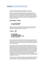
Technical Information8. Pressures between Ropes and Sheaves or DrumsIn addition to bending stresses experienced by wire ropesoperating over sheaves or pulleys, ropes are also subjectedto radial pressure as <strong>the</strong>y make contact with <strong>the</strong> sheave.This pressure sets up shearing stresses in <strong>the</strong> wires,distorts <strong>the</strong> rope’s structure and affects <strong>the</strong> rate of wear of<strong>the</strong> sheave grooves. When a rope passes over a sheave,<strong>the</strong> load on <strong>the</strong> sheave results from <strong>the</strong> tension in <strong>the</strong> ropeand <strong>the</strong> angle of rope contact. It is independent of <strong>the</strong>diameter of <strong>the</strong> sheave.Load on bearing =Assuming that <strong>the</strong> rope is supported in a well fitting groove,<strong>the</strong>n <strong>the</strong> pressure between <strong>the</strong> rope and <strong>the</strong> groove isdependent upon <strong>the</strong> rope tension and diameter but isindependent of <strong>the</strong> arc of contact.Pressure, P =2TDdP = pressure (kg/cm 2 )T = rope tension (kg)D = diameter of sheave or drum (cm)d = diameter of rope (cm)Maximum Permissible PressuresNumber ofouter wiresin strands2T sin θ25 - 8 Ordinary lay5 - 8 Lang’s lay9 - 13 Ordinary lay9 - 13 Lang’s lay14 - 18 Ordinary lay14 - 18 Lang’s layTriangular strandCastironkgf/cm 220253540424755Groove materialLow 11 to 13%carbon Mn steelcast steel orequivalentalloysteelskgf/cm 2 kgf/cm 2404560707585100105120175200210240280It should be emphasised that this method of estimation ofpressure assumes that <strong>the</strong> area of contact of <strong>the</strong> rope in<strong>the</strong> groove is on <strong>the</strong> <strong>full</strong> rope diameter, whereas in fact only<strong>the</strong> crowns of <strong>the</strong> outer wires are actually in contact with <strong>the</strong>groove. The local pressures at <strong>the</strong>se contact points may beas high as 5 times those calculated and <strong>the</strong>refore <strong>the</strong>values given above cannot be related to <strong>the</strong> compressivestrength of <strong>the</strong> groove material.If <strong>the</strong> pressure is high, <strong>the</strong> compressive strength of <strong>the</strong>material in <strong>the</strong> groove may be insufficient to preventexcessive wear and indentation and this in turn will damage<strong>the</strong> outer wires of <strong>the</strong> rope and effect its working life. Aswith bending stresses, stresses due to radial pressureincrease as <strong>the</strong> diameter of <strong>the</strong> sheave decreases.Although high bending stresses generally call for <strong>the</strong> use offlexible rope constructions having relatively small diameterouter wires, <strong>the</strong>se have less ability to withstand heavypressures than do <strong>the</strong> larger wires in <strong>the</strong> less flexibleconstructions. If <strong>the</strong> calculated pressures are too high for<strong>the</strong> particular material chosen for <strong>the</strong> sheaves or drums orindentations are being experienced, consideration shouldbe given to an increase in sheave or drum diameter. Sucha modification would not only reduce <strong>the</strong> groove pressure,but would also improve <strong>the</strong> fatigue life of <strong>the</strong> rope.The pressure of <strong>the</strong> rope against <strong>the</strong> sheave also causedistortion and flattening of <strong>the</strong> rope structure. This can becontrolled by using sheaves with <strong>the</strong> correct groove profilewhich, for general purposes, suggests an optimum grooveradius of nominal rope radius +10%. The profile at <strong>the</strong>bottom of <strong>the</strong> groove should be circular over an angle ofapproximately 120 o , and <strong>the</strong> angle of flare between <strong>the</strong>sides of <strong>the</strong> sheave should be approximately 52 o .Hardness of Rope WireRopegradeMin. TensileStrength2160N / mm 21960N / mm 21770N / mm 21570N / mm 2ApproximateEquivalentAPI 9AGradeEEIPSEIPSIPSPSApproximateHardnessBrinel480 / 500470 / 480445 / 470405 / 425Rockwell‘C’Suggested pulley hardness: 250-300 Brinell for Mn steel orequivalent alloy steel.If <strong>the</strong> calculated pressure is too high for <strong>the</strong> particularmaterial chosen for <strong>the</strong> pulley or drum, considerationshould be given to increase in pulley or drum diameter.Such a modification would not only reduce <strong>the</strong> groovepressure, but would also improve <strong>the</strong> fatigue life of <strong>the</strong> ropeby reducing <strong>the</strong> bending stresses imposed.5251494534 BRIDON <strong>Mining</strong>