FMEDA â Accurate Product Failure Metrics - Exida
FMEDA â Accurate Product Failure Metrics - Exida
FMEDA â Accurate Product Failure Metrics - Exida
- No tags were found...

You also want an ePaper? Increase the reach of your titles
YUMPU automatically turns print PDFs into web optimized ePapers that Google loves.
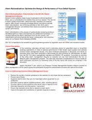
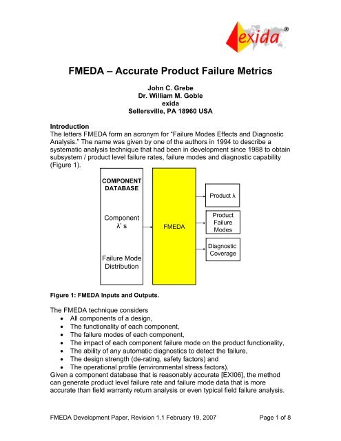
<strong>FMEDA</strong> – <strong>Accurate</strong> <strong>Product</strong> <strong>Failure</strong> <strong>Metrics</strong>John C. GrebeDr. William M. GobleexidaSellersville, PA 18960 USAIntroductionThe letters <strong>FMEDA</strong> form an acronym for “<strong>Failure</strong> Modes Effects and DiagnosticAnalysis.” The name was given by one of the authors in 1994 to describe asystematic analysis technique that had been in development since 1988 to obtainsubsystem / product level failure rates, failure modes and diagnostic capability(Figure 1).COMPONENTDATABASE<strong>Product</strong> λComponentλ’ s<strong>FMEDA</strong><strong>Product</strong><strong>Failure</strong>Modes<strong>Failure</strong> ModeDistributionDiagnosticCoverageFigure 1: <strong>FMEDA</strong> Inputs and Outputs.The <strong>FMEDA</strong> technique considers• All components of a design,• The functionality of each component,• The failure modes of each component,• The impact of each component failure mode on the product functionality,• The ability of any automatic diagnostics to detect the failure,• The design strength (de-rating, safety factors) and• The operational profile (environmental stress factors).Given a component database that is reasonably accurate [EXI06], the methodcan generate product level failure rate and failure mode data that is moreaccurate than field warranty return analysis or even typical field failure analysis.<strong>FMEDA</strong> Development Paper, Revision 1.1 February 19, 2007 Page 1 of 8
An <strong>FMEDA</strong> is an extension of the well proven FMEA technique and can be usedon electrical or mechanical products [GOB03, GOB07].FMEA/FMECAA <strong>Failure</strong> Modes and Effects Analysis, FMEA, is a structured qualitative analysisof a system, subsystem, process, design or function to identify potential failuremodes, their causes and their effects on (system) operation.The concept and practice of performing a FMEA, has been around in some formsince the 1960’s. The practice was first formalized in 1970s with the developmentof US MIL STD 1629/1629A.In early practice its use was limited to select applications and industries wherecost of failure is particularly high. The primary benefits were to qualitativelyevaluate the safety of a system, determine unacceptable failure modes, identifypotential design improvements, plan maintenance activities and help understandsystem operation in the presence of potential faults.The <strong>Failure</strong> Modes, Effects and Criticality Analysis, FMECA, was introduced toaddress a primary barrier to effective use of the detailed FMEA results by theaddition of a criticality metric. This allowed users of the analysis to quickly focuson the most important failure modes/effects in terms of consequence but still didnot address the likelihood or probability of the failure mode which is just asimportant in prioritization to drive improvements based on cost / benefitcomparisons.<strong>FMEDA</strong> DevelopmentThe <strong>Failure</strong> Modes, Effects and Diagnostic Analysis, <strong>FMEDA</strong>, technique wasdeveloped in the late 1980’s based in part on a paper in the 1984 RAMSSymposium [COL84]. The <strong>FMEDA</strong> added two additional pieces of information tothe FMEA analysis process. The first piece of information added in an <strong>FMEDA</strong> isthe quantitative failure data (failure rates and the distribution of failure modes) forall components being analyzed. The second piece of information added to an<strong>FMEDA</strong> is the ability of the system or subsystem to detect internal failures viaautomatic on-line diagnostics. This is crucial to achieving and maintainingreliability in increasing complex systems and for systems that may not be fullyexercising all functionality under normal circumstances such as a low demandEmergency Shutdown System, ESD System.There is a clear need for a measurement of automatic diagnostic capability. Thiswas recognized in the late 1980’s [AME87]. In that context the principles andbasic methods for the modern <strong>FMEDA</strong> were first documented in the bookEvaluating Control System Reliability [Gob92]. The actual term <strong>FMEDA</strong> was first<strong>FMEDA</strong> Development Paper, Revision 1.1 February 19, 2007 Page 2 of 8
used in 1994 [MOR94] and after further refinement the methods were publishedin the late 1990’s [GOB98a, GOBL98b, GOB99]. <strong>FMEDA</strong> techniques have beenfurther refined during the 2000’s primarily during IEC 61508 preparation work.The key changes have been:1. IEC 61508 <strong>Failure</strong> Mode Definitions – New Definitions2. Functional <strong>Failure</strong> Modes3. Mechanical Component UsageWith these changes, the <strong>FMEDA</strong> technique has matured to become morecomplete and useful.<strong>FMEDA</strong> – IEC 61508The IEC 61508 standard officially recognizes the <strong>FMEDA</strong> technique and mostIEC 61508 assessment bodies rely upon <strong>FMEDA</strong> results to verify that sufficientsafety has been achieved for a particular application. Within the field of functionalsafety, standardized failure modes are also defined which also helped to improvethe ease of performing the <strong>FMEDA</strong> and interpreting its results.The official approval of IEC 61508, Part 2 in 2000 provided documentation onwhat is expected of a <strong>FMEDA</strong> and how to use the data in the area of functionalsafety. This has lead to significantly increased use of the <strong>FMEDA</strong> within therelevant industries and a rapid evolution of the methods and tools with therequired component level failure rate and failure mode data.IEC 61508 use of the <strong>FMEDA</strong> is focused on determination of two safety integritymeasurements; the dangerous undetected failure rate and a metric known as theSafe <strong>Failure</strong> Fraction, SFF. The SFF represents the percentage of failures thatare not dangerous and are detected. However, additional quantitative resultsimportant to system level modeling can also be easily derived out of the same<strong>FMEDA</strong> and this has driven further evolution of the process and enhanced thevalue of its results while remaining faithful to the original intent of the IEC 61508.Draft versions of future updates of the IEC 61508 standard are now working tocapture some of these advancements.IEC 61508 <strong>Failure</strong> Mode DefinitionsIEC61508 Part 4 (1998) defines a dangerous failure as a failure which “has thepotential to put the safety-related system in a hazardous or fail-to-function state.”The standard also defines a safe failure as a failure which “does not have thepotential to put the safety-related system in a hazardous or fail-to-function state.”IEC61508 Part 2 further explains a “safe” failure as a failure leading to a safeshut-down or having no impact on the safety integrity of the E/E/PE safetyrelatedsystem.<strong>FMEDA</strong> Development Paper, Revision 1.1 February 19, 2007 Page 3 of 8
This significantly simplified and ambiguous definition of a safe failure, if followed,literally leads to results that do not provide data that is very relevant toapplications and leads to multiple unanticipated interpretations of the standard.Some of these interpretations can provide unintended loop holes that result incircumstances where the addition of unrelated functionality to a product canimprove the SFF metric without any improvement in safety integrity.New <strong>Failure</strong> Mode DefinitionsKey players in the industry, including exida, are dedicated to improvement offunctional safety while remaining faithful to the original intent of IEC61508. exidahas proposed multiple refinements to the failure mode definitions and beganusing those new definitions in 2003 when doing <strong>FMEDA</strong> analysis. The morerefined failure mode definitions are expected to be included in subsequentversions of IEC 61508. To understand the required changes it is first necessaryto better understand the ambiguity of the current official definition of “safe failure.”As currently defined a safe failure includes all failures not considered dangerous.This includes “failure leading to a safe shut-down or having no impact on thesafety integrity of the E/E/PE safety-related system.” A failure that has no impacton the safety integrity function would most likely not even be noticed by a user ofthe product and can fall into two general categories.No Impact – Category 1, No EffectMost components have multiple failure modes and these failure modes are moreor less important depending on how they are used within a particular design. Forinstance failure modes of a resistor include change in value within the range ofone-half to two times its original value, open circuit and short circuit faults. If thisresistor is used as part of an analog circuit monitoring a particular voltage orcurrent level, the drift failure mode will directly result in a significant error inmeasurement and most likely be dangerous.If the same resistor was used in series with the base of a transistor used to drivean on-off relay coil, the product would most likely continue to operate andproduce the desired output state even if the resistor drifts over this relatively widerange of values. Resistor drift in this application has no effect of the functionality.Therefore this failure mode is called “No Effect” as although the component ispart of the desired function this particular failure mode has no effect on thedesired function. If this resistor were to fail open circuit there would be an impacton the function so all failure modes of the component cannot be ignored.No Impact – Category 2, Not a PartThe purpose of some components is to support human interface display andauxiliary functions that are not part of the circuitry providing the functionality ofthe product being relied upon for the application. For instance a resistor can beused to set the current level for an indicating LED that lights up when<strong>FMEDA</strong> Development Paper, Revision 1.1 February 19, 2007 Page 4 of 8
communications are taking place so that it can be easily seen if communicationsare active. <strong>Failure</strong> of the resistor such that the LED does not light up duringcommunications has no impact on the normal operation of the product. In factany of the failure modes of the resistor are unlikely to impact performance of thefunction of the product. This category of components are referred to as “Not apart” since they are not a part of the implementation of the desired function.New Definition of “Safe” <strong>Failure</strong>sNote that “no effect” refers to one particular failure mode of a component that isused by the desired function (and other failure modes of that part will lead to lossof function) and “not a part” refers to an entire component that is not necessaryor used in the implementation of the desired function but both can be considered“safe” by the current IEC61508 definition.A more useful and non-ambiguous definition of a safe failure in the context of asafety system is one that leads to a false trip (in the absence of a fault tolerantarchitecture) which is clearly the opposite of a dangerous failure (failure toperform the safety function or inability to trip when needed). This definition of“safe” also has the additional benefit of providing an estimated false trip rate for asafety product which is also very important to a potential user of the product as ittypically leads to lost production and is possibly an initiating event for anotherhazard scenario.Safe <strong>Failure</strong> Fraction calculationThe remaining question is how the “No Effect” and “Not a part” failure rates areused (or not used) in the calculation of the SFF. The most conservative methodis to exclude both from the calculation which provides the lowest SFF estimatefor a product. This approach only considers the safe and dangerous failures asthose that directly impact the desired safety function. This policy was followed byconservative vendors including exida once the problem was recognized in thetime period approximately represented by the years 2000 through 2002.It is clearly bad policy to count the “Not a part” failures as “safe.” This is becausea product designer with a design that is close to a particular SFF threshold couldpotentially reach that threshold by adding extraneous components which provideno improvement for safety functionality.Around the year 2003 the consensus of the key industry experts in this areasettled on interpretation of the original “safe failures” as the newly defined safefailures plus No Effect but excluding Not a Part failures. The results in the sum ofthe newly defined safe failure and the no effect failures being used for the safefailure portion of the SFF calculation and the “Not a part” failure rates are notconsidered relevant to safety calculations. <strong>FMEDA</strong> result reports beganpublishing numbers for the additional failure rate categories.<strong>FMEDA</strong> Development Paper, Revision 1.1 February 19, 2007 Page 5 of 8
The result of this change is that the total failure rate reported by the <strong>FMEDA</strong>represents the total failure rate for all the components even if some of thosefailure rates do not lead to an observable failure at the product level. Observedfailure rates at the product level are predicted by the total failure rate minus theno effect failure rate because the no effect failures would, in most cases, only bediscovered by full parametric testing of the individual components.Functional <strong>Failure</strong> Mode AnalysisAlso in the early 2000’s functional failure mode analysis was added to the<strong>FMEDA</strong> process. In early <strong>FMEDA</strong> work, component failure modes were mappeddirectly to “safe” or “dangerous” categories per IEC 61508. This was relativelyeasy since everything that was not “dangerous” was “safe.” With multiple failuremode categories now existing, direct assignment became more difficult. Inaddition, it became clear that the category assignment might change if a productwere used in different applications. With direct failure mode category assignmentduring the <strong>FMEDA</strong>, a new <strong>FMEDA</strong> was required for each new application or eachvariation in usage.Under the functional failure mode approach, the actual functional failure modesof the product are identified. During the detailed <strong>FMEDA</strong>, each component failuremode is mapped to a functional failure mode. The functional failure modes arethen categorized according to product failure mode in a particular application.This eliminates the need for more detailed work when a new application isconsidered.Mechanical <strong>FMEDA</strong> TechniquesIt became clear in the early 2000’s that many products being used in safetycritical applications had mechanical components. An <strong>FMEDA</strong> done withoutconsidering these mechanical components was incomplete and potentiallymisleading. The fundamental problem in using the <strong>FMEDA</strong> technique was thelack of a mechanical component database that included part failure rates andfailure mode distributions.Using a number of published reference sources, exida began development of amechanical component database in 2003 [Gob03]. After a few years of researchand refinement [GOB07], the database has been published [exi06]. This hasallowed the <strong>FMEDA</strong> to be used on combination electrical / mechanicalcomponents and purely mechanical components.The FutureThis paper explains how <strong>FMEDA</strong> techniques have evolved over the past decadesince the first efforts to define the process were made. One result of this is that<strong>FMEDA</strong> Development Paper, Revision 1.1 February 19, 2007 Page 6 of 8
older <strong>FMEDA</strong> reports (2002 and before) should not be used and should never becompared to newer work.It is clear that further refinement of the component database with selectivecalibration to different operation profiles is needed. In addition, comparisons of<strong>FMEDA</strong> results with field failure studies have shown that human factors,especially maintenance procedures, have an impact on the failure rates andfailure modes of products. As more data becomes available, these factors canalso be added to <strong>FMEDA</strong> analysis.References[Col84] Collett, R. E. and Bachant, P. W., “Integration of BIT Effectiveness withFMECA,” 1984 Proceedings of the Annual Reliability and MaintainabiltiySymposium, NY: New York, IEEE, 1984.[AME87] H.A. Amer,and E. J. McCluskey, “Weighted Coverage in Fault-TolerantSystems,” 1987 Proceedings of the Annual Reliability and MaintainabiltiySymposium, NY: NY, IEEE, 1987.[GOB92] Goble, W.M., Evaluating Control Systems Reliability, Techniques andApplications, NC: Research Triangle Park, Instrument Society of America, 1992.[MOR94] <strong>FMEDA</strong> Analysis of CDM (Critical Discrete Module) – QUADLOG,Moore <strong>Product</strong>s Co., PA: Spring House, 1994.[GOB98a] Goble, W.M., The Use and Development of Quantitative Reliability andSafety Analysis in New <strong>Product</strong> Design, University Press, Eindhoven Universityof Technology, Netherlands: Eindhoven, 1998.[GOB98b] Goble, W.M., Control Systems Safety Evaluation and Reliability,second edition, NC: Research Triangle Park: ISA, 1998.[GOB99] W. M. Goble and A. C. Brombacher, “Using a <strong>Failure</strong> Modes, Effectsand Diagnostic Analysis (<strong>FMEDA</strong>) to Measure Diagnostic Coverage inProgrammable Electronic Systems,” Reliability Engineering and System Safety,Vol. 66, No. 2, November 1999.[GOB03] W. M. Goble, “<strong>Accurate</strong> <strong>Failure</strong> <strong>Metrics</strong> for Mechanical Instruments,”Proceedings of IEC 61508 Conference, Germany: Augsberg, RWTUV, January2003.[EXi06] Electrical & Mechanical Component Reliability Handbook, exida, PA:Sellersville, 2006. See www.exida.com[GOB07] W.M. Goble and J.V. Bukowski, “Development of a MechanicalComponent <strong>Failure</strong> Database,” 2007 Proceedings of the Annual Reliability andMaintainabiltiy Symposium, NY: NY, IEEE, 2007.<strong>FMEDA</strong> Development Paper, Revision 1.1 February 19, 2007 Page 7 of 8
Revision HistoryRev. 1.0, Goble, Grebe Initial release, February 19, 2007Rev. 1.1, Goble, Grebe Review results included, February 19,2007<strong>FMEDA</strong> Development Paper, Revision 1.1 February 19, 2007 Page 8 of 8