Priming System Type ASVA/B/T 70401 6 - vatec Maschinenbau GmbH
Priming System Type ASVA/B/T 70401 6 - vatec Maschinenbau GmbH
Priming System Type ASVA/B/T 70401 6 - vatec Maschinenbau GmbH

You also want an ePaper? Increase the reach of your titles
YUMPU automatically turns print PDFs into web optimized ePapers that Google loves.
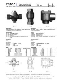
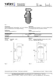
Ansaugsystem Typ/<br />
<strong>Priming</strong> <strong>System</strong> <strong>Type</strong> <strong>ASVA</strong>/B/T <strong>70401</strong> 6<br />
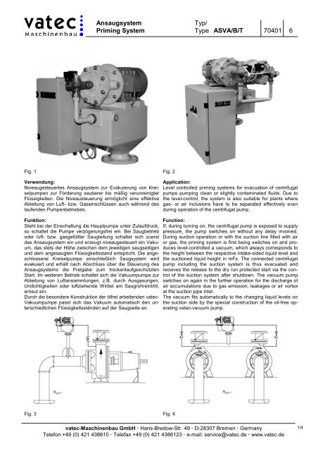
Fig. 1 Fig. 2<br />
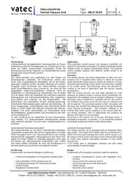
Verwendung:<br />
Niveaugesteuertes Ansaugsystem zur Evakuierung von Kreiselpumpen<br />
zur Förderung sauberer bis mäßig verunreinigter<br />
Flüssigkeiten. Die Niveausteuerung ermöglicht eine effektive<br />
Ableitung von Luft- bzw. Gaseinschlüssen auch während des<br />
laufenden Pumpenbetriebes.<br />
Funktion:<br />
Steht bei der Einschaltung die Hauptpumpe unter Zulaufdruck,<br />
so schaltet die Pumpe verzögerungsfrei ein. Bei Saugbetrieb<br />
oder luft- bzw. gasgefüllter Saugleitung schaltet sich zuerst<br />
das Ansaugsystem ein und erzeugt niveaugesteuert ein Vakuum,<br />
das stets der Höhe zwischen dem jeweiligen saugseitigen<br />
und dem angesaugten Flüssigkeitsstand entspricht. Die angeschlossene<br />
Kreiselpumpe einschließlich Saugsystem wird<br />
evakuiert und erhält nach Abschluss über die Steuerung des<br />
Ansaugsystems die Freigabe zum trockenlaufgeschützten<br />
Start. Im weiteren Betrieb schaltet sich die Vakuumpumpe zur<br />
Ableitung von Luftansammlungen, z.B. durch Ausgasungen,<br />
Undichtigkeiten oder luftziehende Wirbel am Saugrohreintritt,<br />
erneut ein.<br />
Durch die besondere Konstruktion der ölfrei arbeitenden <strong>vatec</strong>-<br />
Vakuumpumpe passt sich das Vakuum automatisch den unterschiedlichen<br />
Flüssigkeitsständen auf der Saugseite an.<br />
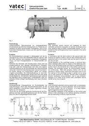
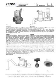
Fig. 3 Fig. 4<br />
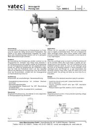
Application:<br />
Level controlled priming systems for evacuation of centrifugal<br />
pumps pumping clean or slightly contaminated fluids. Due to<br />
the level-control, the system is also suitable for plants where<br />
gas- or air inclusions have to be separated effectively even<br />
during operation of the centrifugal pump.<br />
Function:<br />
If, during turning on, the centrifugal pump is exposed to supply<br />
pressure, the pump switches on without any delay involved.<br />
During suction operation or with the suction line filled with air<br />
or gas, the priming system is first being switches on and produces<br />
level-controlled a vacuum, which always corresponds to<br />
the height between the respective intake-sided liquid level and<br />
the suctioned liquid height in mFs. The connected centrifugal<br />
pump including the suction system is thus evacuated and<br />
receives the release to the dry run protected start via the control<br />
of the suction system after shutdown. The vacuum pump<br />
switches on again in the further operation for the discharge of<br />
air accumulations due to gas emission, leakages or air vortex<br />
at the suction pipe inlet.<br />
The vacuum fits automatically to the changing liquid levels on<br />
the suction side by the special construction of the oil-free operating<br />
<strong>vatec</strong>-vacuum pump.<br />
<strong>vatec</strong>-<strong>Maschinenbau</strong> <strong>GmbH</strong> · Hans-Bredow-Str. 49 · D-28307 Bremen · Germany<br />
Telefon +49 (0) 421 438610 · Telefax +49 (0) 421 4386123 · e-mail: service@<strong>vatec</strong>.de · www.<strong>vatec</strong>.de<br />
1/4
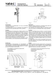
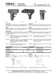
Ausführung: Design:<br />
Typ <strong>ASVA</strong>: Standardausführung gemäß Fig.1. <strong>Type</strong> <strong>ASVA</strong>: Standard design as per Fig.1<br />
Typ ASVB: Wie Ausführung <strong>ASVA</strong>, jedoch mit eingebautem<br />
vakuumgesteuerten Absperrventil für Anlagen,<br />
in denen der saugseitige Flüssigkeitsstand<br />
die Aufstellungshöhe des Ansaugautomaten<br />
überschreiten kann.<br />
Typ <strong>ASVA</strong>/B-T: Wie Typ <strong>ASVA</strong>/ASVB, jedoch mit zwei Flüssigkeitsring-Vakuumpumpen,<br />
die in zyklischer<br />
Vertauschung arbeiten. Fig.2<br />
Komponenten der anschlussfertigen Standardausführung:<br />
- Flüssigkeitsring-Vakuumpumpe<br />
- Vakuumbehälter mit Niveauschaltung<br />
- Betriebsflüssigkeits-Magnetventil<br />
- Interne Verrohrung mit Kugelrückschlagventil<br />
- angebautes Steuergerät<br />
Sonderzubehör/-Ausführungen:<br />
- Angebauter- oder separater Umlaufbehälter für eine unabhängige<br />
Versorgung der Vakuumpumpen mit Betriebsflüssigkeit.<br />
- Ausführung des Steuergerätes mit Abschaltautomatik für<br />
die Kreiselpumpe (siehe "Steuerung")<br />
- Ausführung für den Einsatz im Ex-Bereich.<br />
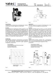
- <strong>vatec</strong>-Saugrohreinlaufdüse Typ SDS/SDF zur Verminderung<br />
der Eintrittsverluste und Verzögerung der Bildung<br />
luftziehender Wirbel am Eintritt von Pumpensaugleitungen<br />
Steuerung: Control:<br />
Angebautes Steuergerät mit Kontakt zur Ferneinschaltung<br />
sowie potentialfreien Kontakten für Startfreigabe der Kreiselpumpe<br />
und Sammelstörmeldung.<br />
Abschaltautomatik Kreiselpumpe (Sonderausführung):<br />
Überschreitet die Vakuumpumpe während einer Nachevakuierung<br />
die vorgebende Laufzeit, kann das Signal zur Abschaltung<br />
der Kreiselpumpe zum Schutz vor Trockenlauf verwendet<br />
werden.<br />
Zyklische Vertauschung der Vakuumpumpen (nur <strong>ASVA</strong>-T<br />
und ASVB-T):<br />
Zur Verkürzung der Evakuierungszeit schalten sich bei der<br />
erstmaligen Vorevakuierung beide Vakuumpumpen gleichzeitig<br />
ein. Während der Nachevakuierungen arbeiten beide<br />
im Wechselbetrieb, dabei ist die eine Vakuumpumpe Betriebspumpe<br />
während die andere als Reservepumpe zur<br />
Verfügung steht. Die Zuschaltung der jeweiligen Reservepumpe<br />
erfolgt entweder durch Laufzeitüberschreitung oder<br />
Störungen der Betriebspumpe<br />
2/4<br />
<strong>Type</strong> ASVB: Same as type <strong>ASVA</strong>, but equipped with integrated<br />
vacuum controlled shut-off valve for use<br />
in plants where overpressure on suction side<br />
may arise.<br />
<strong>Type</strong> <strong>ASVA</strong>/B-T: Same as type <strong>ASVA</strong>/ASVB, but equipped with<br />
two liquid ring vacuum pumps, working in cycling<br />
interchange. Fig.2<br />
Components of the standard execution ready for connection:<br />
- Liquid ring vacuum pump<br />
- Vacuum tank with level control<br />
- Service liquid solenoid valve<br />
- Internal piping with non-return ball valve<br />
- Mounted control unit<br />
Special accessories/designs:<br />
- Mounted or separate circulation tank for an independent<br />
supply of the vacuum pumps with service liquid.<br />
- Design of control gear with shut-off automatic for the centrifugal<br />
pump (see" Control Unit")<br />
- Design for the application in the Ex-area.<br />
- <strong>vatec</strong> suction pipe inlet nozzle <strong>Type</strong> SDS/SDF for the reduction<br />
of entrance losses and delay regarding the formation of<br />
air-vortex at the entrance of pump suction lines.<br />
Mounted control unit with contact for remote control and potential<br />
free contacts for start release of the centrifugal pump and<br />
report on disturbances.<br />
Shut-off automatic centrifugal pump (Special design):<br />
The signal for the shut-off of the centrifugal pump can be used<br />
for the protection of dry run, if the vacuum pump exceeds the<br />
specified cycling time during a re-evacuation.<br />
Cyclic exchange of the vacuum pumps (<strong>Type</strong> <strong>ASVA</strong>-T and<br />
ASVB-T only):<br />
Both vacuum pumps switch on simultaneously at the initial<br />
evacuation for the reduction of the evacuation time. Both pumps<br />
are working in alternating operation during the re-evacuations,<br />
whereby one vacuum pump is the operating pump while the<br />
other is available as reserve pump. The connection of the corresponding<br />
reserve pump is effected either in case the cycling<br />
time is exceeded or in case of defects to the operating pump.<br />
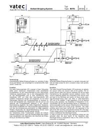
Installationshinweise: Installation Instructions:<br />
Anschlüsse Connections<br />
Entlüftung Saugseite A1 Venting suction side<br />
Entlüftung Druckseite A2 Venting discharge side<br />
Abluft / Drainage B Exhaust / Drainage<br />
Betriebsflüssigkeit W1 Service Liquid<br />
<strong>vatec</strong>-<strong>Maschinenbau</strong> <strong>GmbH</strong> · Hans-Bredow-Str. 49 · D-28307 Bremen · Germany<br />
Telefon +49 (0) 421 438610 · Telefax +49 (0) 421 4386123 · e-mail: service@<strong>vatec</strong>.de · www.<strong>vatec</strong>.de
Das Ansaugsystem ist mindestens 1 m oberhalb dem höchsten<br />
zu entlüftenden Punkt aufzustellen. Die maximale Aufstellungshöhe<br />
über dem niedrigsten saugseitigen Flüssigkeitsstand<br />
darf bei Wasser nicht mehr als 7,5m, abzüglich der<br />
dynamischen Verluste des Saugsystems betragen.<br />
Die Evakuierung erfolgt über steigend zu verlegende Leitungen<br />
mit saugseitigem Anschluss A1 und drosselbarem druckseitigen<br />
Anschluss A2.<br />
Über den Anschluss W1 erfolgt die Betriebsflüssigkeitsversorgung<br />
der Vakuumpumpen.<br />
Die Abluftleitung B ist über eine ständig offene Leitung mit<br />
Gefälle drucklos zur Drainage zu leiten. Hier tritt das Gemisch<br />
aus zugeführter Betriebsflüssigkeit und Abluft aus.<br />
Betriebsflüssigkeit: Service liquid:<br />
Die Flüssigkeitsring-Vakuumpumpe benötigt während des<br />
Betriebes geeignete Flüssigkeit wie z.B. Wasser. Die Versorgung<br />
erfolgt vorzugsweise aus einem Druckwassernetz. Die<br />
Betriebsflüssigkeit darf nicht zum Schäumen neigen und die<br />
Bauteile der Pumpe nicht angreifen. In Sonderausführung<br />
kann die Anlage mit angebautem oder separatem Betriebsflüssigkeits-Umlaufbehälter<br />
zur unabhängigen Versorgung der<br />
Vakuumpumpen ausgeführt werden.<br />
The <strong>Priming</strong> <strong>System</strong> has to be installed at least 1 m above the<br />
highest ventilating point. In case of water as pumping media<br />
the maximum installation height over the lowest intake-sided<br />
liquid level must not exceed 7.5m, minus the dynamical losses<br />
of the suction system.<br />
The evacuation occurs via pipes to be installed ascending to<br />
the suction side connection A1 and to the throttled discharge<br />
side connection A2.<br />
Service liquid is supplied to the vacuum pumps via connection<br />
W1.<br />
The exhaust line B has to be guided without back pressure via<br />
a permanent open line with drop to the drainage. The mixture<br />
of fed operating liquid and exhaust escapes here.<br />
The liquid ring vacuum pump requires suitable liquid such as<br />
water during operation. Supply is preferably effected from a<br />
pressure water network. The operating liquid must not tend to<br />
bubbles and must not attack the components of the pump. In<br />
special design the system can be equipped with installed or<br />
separate service liquid circulation tank for independent supply<br />
of the vacuum pumps.<br />
Technische Daten: Technical Data:<br />
TYP<br />
Einheit<br />
Unit<br />
1327 1351 2081 2388 <strong>Type</strong><br />
Betriebsspannung<br />
400 V 50 Hz / 440 V 60 Hz<br />
Hz 50 60 50 60 50 60 50 60<br />
Operating voltage<br />
400 V 50 Hz / 440 V 60 Hz<br />
Saugleistung l / min 350 400 700 800 1400 1700 1900 2100 Suction capacity<br />
Drehzahl min -1 2880 3450 2880 3450 1450 1750 1450 1750 Rotations<br />
Antriebsleistung kW 2,2 2,8 3,0 3,6 4,0 4,8 7,5 9,0 Power input<br />
Schutzart IP55 IP55 IP55 IP55 Protection<br />
Nenndruck PN6 PN6 PN6 PN6 Nominal pressure<br />
Betriebsflüssigkeit<br />
erforderlich<br />
l / min<br />
bar<br />
5<br />
2-5<br />
6<br />
2-5<br />
8<br />
2-5<br />
8<br />
2-5<br />
Service liquid required<br />
Werkstoffe: Materials:<br />
Vakuumbehälter GG25 G-CuSn10 1.4408 Vacuum tank Cast iron (GG25) Bz (G-CuSn10) SS (1.4408)<br />
Pumpengehäuse GG25 G-CuSn10 1.4408 Pump casing Cast iron (GG25) Bz (G-CuSn10) SS (1.4408)<br />
Laufrad G-CuSn10 1.4408 Impeller Bz (G-CuSn10) SS (1.4408)<br />
Dichtungen NBR Viton Sealings NBR Viton<br />
Ventilgehäuse G-CuSn10 Valve casing Bz (G-CuSn10)<br />
<strong>vatec</strong>-<strong>Maschinenbau</strong> <strong>GmbH</strong> · Hans-Bredow-Str. 49 · D-28307 Bremen · Germany<br />
Telefon +49 (0) 421 438610 · Telefax +49 (0) 421 4386123 · e-mail: service@<strong>vatec</strong>.de · www.<strong>vatec</strong>.de<br />
3/4
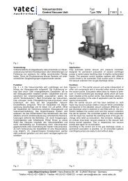
Maße: Dimensions:<br />
Fig. 5 <strong>ASVA</strong>/B 1327-1351 Fig. 6 <strong>ASVA</strong>/B 2081-2388<br />
Fig. 7 <strong>ASVA</strong>/B-T 1327-1351 Fig. 8 <strong>ASVA</strong>/B-T 2081-2388<br />
4/4<br />
Typ/<strong>Type</strong> 1327 1327-T 1351 1351-T 2081 2081-T 2388 2388-T<br />
A1 DN80 DN80 DN80 DN80 DN80 DN100 DN80 DN100<br />
A2 G1/2“ G1/2“ G1/2“ G1/2“ G1/2“ G1/2“ G1/2“ G1/2“<br />
B G3/4“ G3/4“ G1“ G1“ G1 1/2“ G1 1/2 DN50 DN50<br />
W1 G1/4“ G1/2“ G1/4“ G1/2“ G3/8“ G1/2“ G3/8“ G1/2“<br />
H mm 520 710 555 740 730 875 872 965<br />
L1 mm 415 500 480 500 445 720 445 755<br />
L2 mm 190 210 215 210 495 720 508 755<br />
M mm 345 350 345 350 180 300 235 300<br />
N mm 130 250 165 295 400 400 440 440<br />
Flansche nach DIN EN 1092-1, PN10 (DIN2501) Flanges according to DIN EN 1092-1, PN10 (DIN2501)<br />
Sonderausführungen auf Anfrage / Änderungen vorbehalten Special design upon request / Subject to change<br />
<strong>vatec</strong>-<strong>Maschinenbau</strong> <strong>GmbH</strong> · Hans-Bredow-Str. 49 · D-28307 Bremen · Germany<br />
Telefon +49 (0) 421 438610 · Telefax +49 (0) 421 4386123 · e-mail: service@<strong>vatec</strong>.de · www.<strong>vatec</strong>.de