Mitutoyo1001 Catalog.pdf - JW Donchin CO.
Mitutoyo1001 Catalog.pdf - JW Donchin CO.
Mitutoyo1001 Catalog.pdf - JW Donchin CO.
- No tags were found...

Create successful ePaper yourself
Turn your PDF publications into a flip-book with our unique Google optimized e-Paper software.
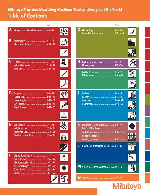
Mitutoyo Precision Measuring Machines Trusted throughout the WorldTable of ContentsAPagesMeasurement Data Management...A-1—14PagesG Linear Gage.......................................G-1 – 20Laser Scan Micrometer.....................G-21 – 33B Micrometers......................................B-1 – 54Micrometer Heads............................B-55 – 76C Holtests .............................................C-1 – 10Inside Micrometers...........................C-11 – 19Bore Gages........................................C-20 – 32H Digimatic Scale Units........................H-1 – 7Linear Scales......................................H-8 – 20I Profile Projectors...............................I-1 – 17Microscopes.......................................I-18 – 44D Calipers..............................................D-1 – 33Height Gages.....................................D-34 – 47Linear Height.....................................D-44 – 45QM Height.........................................D-46 – 47Depth Gages......................................D-48 – 56J Surftest..............................................J-1 – 15Formtracer.........................................J-16 – 29Contracer...........................................J-30 – 39Roundtest..........................................J-40 – 56E Gage Blocks.......................................E-1 – 24Height Master...................................E-25 – 32Reference Gages...............................E-33 – 58Granite Surface Plate........................E-59 – 61K Hardness Testing Machine...............K-1 – 11Rockwell HardnessTesting Machines..............................K-12 – 16Portable HardnessTesting Machine................................K-17 – 19L Coordinate Measuring Machines.....L-1 – 12F Digimatic Indicators..........................F-1 – 13Dial Indicators...................................F-14 – 46Dial Test Applications.......................F-47 – 60Thickness Gages................................F-49 – 52Other Gages......................................F-54 – 60Stand..................................................F-61 – 64M Vision Measuring System.................M-1 – 9NINDEX..................................................N-1– 9i
Mitutoyo North America OperationsMitutoyo America CorporationCorporate HeadquartersAurora, Illinois USA(630) 820-9666Mitutoyo Canada Inc.Corporate HeadquartersMississauga, Ontario Canada(905) 821-1261Mitutoyo MexicoCorporate HeadquartersEstado de Mexico, Mexico(0155) 5312-5612Mitutoyo America CorporationEstablished in 1963, Mitutoyo AmericaCorporation has locations all across the USand Canada, including corporate offices, salesoffices, M 3 Solution Centers, calibration andrepair laboratories, and research and developmentfacilities. Mitutoyo America offers a full productline of precision measuring tools, instruments andequipment. Mitutoyo provides a comprehensivemetrology organization, with dependable productand technical support, state-of the-art calibrationand repair services, unmatched education andtraining programs and cutting-edge researchand development. As the leading metrologycompany in the world, Mitutoyo is committedto future product development that appliesbreakthrough technologies to its full range ofdimensional measurement tools, instrumentsand systems. With the belief that providinghigh quality metrology goods and services toits customers will in turn, allow its customers toprovide high quality product to theirs, Mitutoyocontinues to develop the most advanced andsophisticated metrology equipment available.”Precision is our profession” is not just thecompany motto, but also the principle by whichevery Mitutoyo employee stands when servingour customers.Precision is our ProfessionCorporate HeadquartersM 3 Solution CenterMitutoyo Institute of MetrologyCT LabCalibration LaboratoryRepair and Field ServiceMicro Encoder Inc R&Dii
One number to serve you better:Toll Free: 1-888-MITUTOYO (1-888-648-8869)(US Inquiries Only)Aurora945 Corporate BlvdAurora, IL 60502(630) 978-5385 Mitutoyo Institute of MetrologyAurora958 Corporate BlvdAurora, IL 60502(630) 978-5385Elk Grove VillageCalibration Lab2025 Tonne RoadElk Grove Village, IL 60007(847) 593-7750 Mitutoyo Tools and instruments can be seen and demonstrated conveniently at any one of nine Mitutoyo M 3 Centersnationwide. These centers are fully equipped featuring operational models of the latest Mitutoyo tools and instruments.By appointment or walk-in basis, product demonstrations at M 3 Solution Centers are carried out by our experienced,highly trained staff. Contact your Mitutoyo distributor or the Mitutoyo regional office near you for more information.Boston1 Park Drive, Suite 11Westford, MA 01886(978) 692-8765Los Angeles16925 East Gale Ave.City of Industry, CA 91745(626) 961-9661Charlotte11515 Vanstory Drive, Suite 150Huntersville, NC 28078(704) 875-8332Toronto2121 Meadowvale BlvdMississauga, Ontario CanadaL5N 5N1(905) 821-1261Cincinnati6220 Hi-Tek CourtMason, OH 45040(513) 754-0709Montréal7075 Robert-Joncas Place, Suite 129Montreal, Quebec CanadaH4M 2Z2(514) 337-5994Detroit44768 Helm StreetPlymouth, MI 48170(734) 459-2810iii
Contact InformationOne number to serve you better:Toll Free: 1-888-MITUTOYO (1-888-648-8869)(US Inquiries Only)Product Sales Support• Product Information• Product and Part Availability• Pricing• QuotationsAll Products Phone: (630) 978-5385Fax: (630) 978-3501CMM Phone: (630) 723-3516Fax: (630) 978-5388Vision Phone: (630) 723-3516Fax: (630) 978-5388Form Phone: (734) 738-5529Fax: (734) 459-0455Canada Phone: (905) 821-1261www.mitutoyo.ca Fax: (905) 821-4968M 3 Solution Centers• Demonstrations• Application supportAll US Offices Phone: (888) 648-8869Toronto Phone: (905) 821-1261Montreal Phone: (514) 337-5994Calibration ServicesElk Grove, IL Calibration LabPhone: (847) 593-7750Fax: (847) 593-7758Canadian Calibration LabOther Product ServicesPhone: (905) 821-1261Fax: (905) 821-4968Repair ServicesAurora Phone: (630) 820-3334Fax: (630) 820-2530Los Angeles Phone: (626) 961-9661Fax: (626) 961-8931Canadian Repair ServicesPhone: (905) 821-1261Fax: (905) 821-4968Field Services (CMM and Precision Instruments)Phone: (630) 820-9590Fax: (630) 820-9110Parts—GeneralPhone: (630) 978-5385Fax: (630) 978-3501Parts—CMM and Precision InstrumentsPhone: (630) 820-9590Fax: (630) 820-9110Technical Support Services• Hardware / Software Technical Support• Application supportCanadian Field ServicesPhone: (905) 821-1261Fax: (905) 821-4968Precision Tools and Instruments (Hardware)Phone: (630) 820-9785 option 2Email: tech.support@mitutoyo.comCMM/Vision/Form SoftwarePhone: (630) 820-9785 option 1Email: software.support@mitutoyo.comMeasurLink Phone (630) 723-3588Email: measurlink@mitutoyo.comEducation Services• Seminars• TextbooksMitutoyo Institute of MetrologyPhone: (630) 978-6469Fax: (630) 978-6471Marketing Services• Product LiteratureUS Phone: (630) 723-3614Fax: (630) 978-5394Canada Phone: (905) 821-1261Fax: (905) 821-4968iv
www.mitutoyo.comThe new US-1001 <strong>Catalog</strong> isavailable on-lineAt www.mitutoyo.com you can find:• Company Information• Complete Product Information• Product Literature• Sales and Promotions• Distributor Locator• Support Services and Contacts• Knowledge Bases• Frequently Asked Questions (FAQs)• Education ServicesWe want to provide our customers with the very bestMetrology products, services and information that they canfind anywhere. Find it all in one easy to reach location atwww.mitutoyo.com.Get up to date product information for over 5000 Mitutoyoproducts. See the latest sales and promotions and accessa variety of product services from one source—when youneed it.You want the best. You want it fast. Come see what wehave to offer at: www.mitutoyo.comFor Canada visit: www.mitutoyo.cav
Company Profile Product Demonstration / Application Support (M 3 Solutions Centers)With 9 locations across North America, Mitutoyo’s M 3 Solutions Centers provide hands on access to the full range of Mitutoyo Precision Tools and Instruments,including the latest technologies Mitutoyo has to offer. Available to walk-ins or by appointment, highly trained and industry experienced applications engineerswill provide product demonstrations, answer questions and assist in the development of application specific solutions. Contact your Mitutoyo distributor or theM3 Solutions Center in your area for additional information.Sales Support / Customer ServiceTo ensure fast, dependable responses to all product-related questions and needs, Mitutoyo America Corporation’s Sales Support group is available to assistwith information on all Mitutoyo precision tools and instruments. Friendly, knowledgeable customer service representatives can provide product specifications,availability, and pricing as well as recommend a local distributor authorized to sell Mitutoyo Products.Technical Support ServicesFast technical support for all Mitutoyo precision tools, instruments and software applications is available to distributors and customers though Mitutoyo’stechnical support services and is just one phone call away. Highly skilled engineers and technicians possessing a wealth of knowledge on all Mitutoyo productscan provide product information, answer technical questions, and offer application guidance. Contract programming and inspection services utilizing our mostadvanced technologies are also available.Software Application TrainingTo maximize the value of Mitutoyo precision instrument purchases, Mitutoyo America Corporation provides customized end user training for all CMM, Vision,Form, and data management (MeasurLink) software applications it provides. Highly trained, industry knowledgeable software instructors provide hands-onone-on-one or group training with content appropriate for all customer needs. Training classes can be arranged at locations throughout North America.vi
Calibration ServicesMitutoyo America Corporation’s calibration laboratory utilizes state-of the art technology to calibrate virtually any metrology tool made. A2LA accredited toISO/IEC 17025 for testing and calibration labs, this facility employs professional calibration technicians to provide NIST-traceable accuracy certification as wellas calibration services for Mitutoyo and other manufacturer's gages and gage blocks. Canadian calibration laboratory is CLAS accredited to ISO/IEC 17025.Field ServicesCommitted to ensuring value and longevity in its products, Mitutoyo America Corporation provides field services for all of its major measuring instrumentproducts. A fully-staffed field service department will arrange the installation, repair, and A2LA accredited calibration of Mitutoyo metrology instruments.Capable of certifying calibration on any service visit, Mitutoyo’s accredited field service technicians get equipment back into production quickly. Serviceagreements are available at the time of equipment purchase. Canadian field service laboratory is CLAS accredited to ISO/IEC 17025.Repair ServicesMitutoyo America Corporation’s in-house repair facilities are capable of repairing the full range of Mitutoyo precision tools. Skilled technicians provide qualityrepairs backed by a full 90-day warranty on parts and labor. When sending an item in for repair, address the package to one of our two repair centers, 958Corporate Blvd., Aurora, IL, or City of Industry, CA. Please include complete contact information in the package, including a fax number and a brief descriptionof the problem. Once received, the item will be evaluated for repair requirements, and a repair estimate will be faxed to you. When sending in items for repair,it is not necessary to contact us in advance for a returned merchandise or returned goods authorization (RMA or RGA). Repair service is also available in Canada.Parts CenterMitutoyo America Corporation’s product parts center stocks over 10,000 individual parts for Mitutoyo products. Same day and 24-hour shipping is availablefor most part requests. For CMM parts, a specialized group is available to provide additional CMM support services. A Mitutoyo product parts catalog isavailable on CD-ROM through the Parts Center or through a local Mitutoyo distributor.Mitutoyo Institute of MetrologyThe Mitutoyo Institute of Metrology provides training and metrology seminars on topics ranging from basic principles of metrology to advanced QC studies.The institute is a premier educational facility within the quality field with over 5,000 students per year taking our courses. Seminars are led by experienced,industry-leading professionals at locations across the US and Canada. Seminars can also be arranged for customers to be held at their own facilities. Allcourses are approved for CEU credits (Continued Education Units).CT Lab / MEI (R&D and Software Development)Mitutoyo America’s CTLabs and Micro Encoder Inc. are part of an international network of Mitutoyo research and development facilities charged with theresponsibility of developing breakthrough technologies for application to the company’s range of dimensional measurement tools, instruments and systemsand for the advancement of the field of metrology in general. Highly skilled developers and engineers utilize cutting edge development tools to producethe most advanced and sophisticated metrology software and equipment available. Mitutoyo America Corporation is a Microsoft ® Gold Certified Partner,providing the entire organization access to a host of Microsoft ® development tools and support, and helping to ensure that Mitutoyo software applicationswork reliably in Microsoft ® OS and network environments.vii
Global NetworkSince the establishment of its first micrometer factory in Japan in 1934, Mitutoyo Corporation has expanded its operations throughoutthe world. Mitutoyo currently maintains 58 sales, manufacturing, engineering and R&D facilities in 26 countries, and has established asuperior network of distributors in 80 countries internationally. Mitutoyo retains its premier status as a leading global metrology providerby satisfying the unique precision measurement needs of every regional market that it serves.Koshin Business CenterMitutoyo Messßeräte GmbH Mitutoyo (UK) L.td. Mitutoyo France S.A.R.LHeadquartersKawasaki Research andDevelopment CenterMitutoyo Italiana S.R.L Mitutoyo Nederland B.V. Mitutoyo Belgium N.V.Tsukuba LaboratoryKiyohara ManufacturingDepartmentUtsunomiya Operations■ Headquarters■ Sales■ Service Center■ Calibration Center■ M 3 Solution Center■ Mitutoyo Institute ofMetrology■ Research andDevelopment Facility■ Manufacturing FacilityGermanyMitutoyo Messßeräte GmbHHead OfficeTEL:49(2137)102-0 FAX:49(2137)86 85E-mail:info@mitutoyo.deM 3 Solution Center HamburgTEL:49(40)791894-0 FAX:49(40)791894-50M 3 Solution Center LeonbergTEL:49(7152)60 80-0 FAX:49(7152)60 80 60M 3 Solution Center BerlinTEL:49(30)2611 267 FAX:49(30)26 29 209M 3 Solution Center EisenachTEL:49(3691)88909-0 FAX:49(3691)88909-9M 3 Solution Center IngolstadtTEL:49(841)954920 FAX:49(841)9549250C.T.L. GermanyTEL:49(7423)8776-0 FAX:49(7423)8776-99U.K.Mitutoyo (UK) Ltd.TEL:44(1264)353123 FAX:44(1264)354883M 3 Solution Center CoventryTEL:44(2476)426300 FAX:44(2476)426339M 3 Solution Center HalifaxTEL:44(1422)375566 FAX:44(1422)328025M 3 Solution Center East KilbrideTEL:44(1355)581170 FAX:44(1355)581171FranceMitutoyo France S.A.R.LTEL:33(1)-49-38-35-00 FAX:33(1)-48-63-27-70E-mail:mitutoyo@mitutoyo.frM 3 Solution Center LYONTEL:33(1)-49-38-35-70 FAX:33(1)-49-38-35-79E-mail:lyon@mitutoyo.frM 3 Solution Center STRASBOURGTEL:33(1)-49-38-35-80 FAX:33(1)-49-38-35-89E-mail:strasb@mitutoyo.frM 3 Solution Center CLUSESTEL:33(1)-49-38-35-90 FAX:33(1)-49-38-35-99E-mail:cluses@mitutoyo.frItalyMitutoyo Italiana S.R.L.TEL:39(02)935781 FAX:39(02)9373290•9373380M 3 Solution Center ModenaTEL:39(059)30 27 17 FAX:39(059)30 27 17M 3 Solution Center PadovaTEL:39(049)87 36 244 FAX:39(049)87 36 244M 3 Solution Center TorinoTEL:39(011)94 91 538 FAX:39(011)94 94 809M 3 Solution Center ChietiTEL:39(0872)70 9217 FAX:39(0872)70 9217NetherlandsMitutoyo Nederland B.V.Sales and ServiceTEL:31-318-534911 FAX:31-318-534913FactoryTEL:31-318-534911 FAX:31-318-534811Mitutoyo Research Center Europe B.V.TEL:31-499-320200 FAX:31-499-320299BelgiumMitutoyo Belgium N.V.TEL:32(3)2540444 FAX:32(3)2540445SwedenMitutoyo Scandinavia ABHead OfficeTEL:46(8)594 109 50 FAX:46(8)590 924 10M 3 Solution Center AlingsåsTEL:46(322)633102 FAX:46(322)633162M 3 Solution Center VärnamoTEL:46(370)46333 FAX:46(370)46334SwitzerlandMitutoyo Schweiz AGTEL:41(0)447361150 FAX:41(0)447361151JapanHeadquartersTEL (044) 813-8201 FAX (044) 813-8210SalesTohoku Business CenterTEL (022) 231-6881 FAX (022) 231-6884Kitakanto Business CenterTEL (028) 660-6240 FAX (028) 660-6248Minamikanto Business CenterTEL (044) 813-1611 FAX (044) 813-1610Koshin Business CenterTEL (0266) 53-6414 FAX (0266) 58-1830Tokai Business CenterTEL (0566) 98-7070 FAX (0566) 98-6761Kansai Business CenterTEL (06) 6613-8801 FAX (06) 6613-8817Seibu Business CenterTEL (092) 411-2911 FAX (092) 473-1470Measuring Tools Customer DeskTEL (044) 822-5151 FAX (044) 813-1691Service CentersTechnical Service CenterTEL (044) 813-8213 FAX (044) 822-4136Overseas Technical SCTEL (044) 813-8247 FAX (044) 822-4136Calibration CentersMeasurement Standard CCTEL (028) 667-4814 FAX (028) 667-8453Utsunomiya CCTEL (028) 656-1432 FAX (028) 656-8443Kawasaki CCTEL (044) 813-8214 FAX (044) 813-8223Hiroshima CCTEL (0823) 74-5462 FAX (0823) 73-5199M 3 Solution CentersUTSUNOMIYATEL (028) 660-6240 FAX (028) 660-6248TOKYOTEL (044) 813-1611 FAX (044) 813-1610SUWATEL (0266) 53-6414 FAX (0266) 58-1830ANJOTEL (0566) 98-7070 FAX (0566) 98-6761OSAKATEL (06) 6613-8801 FAX (06) 6613-8817FUKUOKATEL (092) 411-2911 FAX (092) 473-1470Mitutoyo Metrology InstituteMitutoyo Metrology Institute (Tokyo)TEL (044) 822-4124 FAX (044) 822-4000Mitutoyo Metrology Institute (Osaka)TEL (06) 6613-8810 FAX (06) 6613-8821Research and Development FacilitiesTsukuba LaboratoryTEL (029) 839-1022 FAX (029) 839-1023Kawasaki Research and Dev. CenterTEL (044) 822-4137 FAX (044) 822-4127Manufacturing FacilitiesKawasaki Research and DevelopmentCenter Manufacturing DepartmentTEL (044) 822-4132 FAX (044) 844-9835Utsunomiya OperationsManufacturing Department 1TEL (028) 656-1117 FAX (028) 656-2164Utsunomiya Operations KiyoharaManufacturing DepartmentTEL (028) 667-4811 FAX (028) 667-4810Nakatsugawa PlantTEL (0573) 68-8201 FAX (0573) 68-8210Hiroshima Operations KureManufacturing Dept.TEL (0823) 71-6111 FAX (0823) 73-2193Hiroshima Operations ShiwaManufacturing DepartmentTEL (082) 433-2077 FAX (082) 433-2695Hiroshima Operations GoharaManufacturing DepartmentTEL (0823) 77-1721 FAX (0823) 77-1724Hiroshima Operations MiyazakiManufacturing DepartmentTEL (0985) 86-2591 FAX (0985) 86-0827Onomi PlantTEL (08895) 7-2036 FAX (08895) 7-2178viii
■ Sales■ Research andDevelopment Facility■ Manufacturing FacilityPT. Mitutoyo IndonesiaMitutoyo MeasuringInstruments (Shanghai) Co., Ltd.Mitutoyo (Thailand) Co., Ltd.Mitutoyo MeasuringInstruments (Suzhou) Co., Ltd.Mitutoyo Schweiz AG Mitutoyo Scandinavia AB Mitutoyo Asia Pacific Pte. Ltd.Regional HeadquartersPolandMitutoyo Polska Sp.z o.o.TEL:48(71)354 83 50 FAX:48(71)354 83 55CzechMitutoyo Cesko, s.r.o.TEL:420-417-579-866 FAX:420-417-579-867HungaryMitutoyo Hungária Kft.TEL:36(1)2141447 FAX:36(1)2141448E-mail:info@mitutoyo.huSingaporeMitutoyo Asia Pacific Pte. Ltd.Regional HeadquartersTEL:(65)62942211 FAX:(65)62996666E-mail:mapsg@mitutoyo.com.sgMalaysiaMitutoyo (Malaysia) Sdn. Bhd.Head OfficeTEL:(60)3-78459318 FAX:(60)3-78459346E-mail:sales dept.@mitutoyo.com.myPenang BranchTEL:(60)4-6411998 FAX:(60)4-6412998E-mail:mmsbpen@po.jaring.netJohor BranchTEL:(60)7-3521626 FAX:(60)7-3521628E-mail:mmsbjhr@po.jaring.myThailandMitutoyo (Thailand) Co., Ltd.TEL:(66)2-521-6130~35 FAX:(66)2-521-6136E-mail:office@mitutoyo.co.thCholburl BranchTEL:(66)038-345-783/7 FAX:(66)038-345-788E-mail:office@mitutoyo.co.thIndonesiaPT. Mitutoyo IndonesiaTEL:(62)21-8980841 FAX:(62)21-8980842E-mail:sales@mitutoyo-indonesia.comVietnamMitutoyo Asia Pacific Pte, Ltd.Ho Chi Minh Representative OfficeTEL:(84)8-5174561 FAX:(84)8-5174582E-mail:mitutoyo@fmail.vnn.vnHanoi Representative OfficeTEL:84(4)-7688963 FAX:84(4)-7688960E-mail:mitutoyo-hn@fmail.vnn.vnPhilippinesMitutoyo Asia Pacific Pte. Ltd.Philippine Representative OfficeTEL:(63)2-842-9305/6 FAX:(63)2-842-9307E-mail:map_phils@pacific.net.phIndiaMitutoyo South Asia Pvt. Ltd.Delhi OfficeTEL:91(11)2637-2090 FAX:91(11)2637-2636Mumbai BranchTEL:91(22)2570-0684, 837, 839 FAX:91(22)2570-0865Pune BranchTEL:91(20)5603-3643, 45, 46 FAX:91(20)5603-3644Bangalore BranchTEL:91(80)2563-0946, 47, 48 FAX:91(80)2563-0949Chennai BranchTEL:91(44)2432-8823, 24 FAX:91(44)2432-8825ChinaMitutoyo Measuring Instruments(Suzhou) Co., Ltd.TEL:86(512)6252-2660 FAX:86(512)6252-2580Mitutoyo Corporation Beijing officeTEL:86(10)65908505 FAX:86(10)65908507Mitutoyo Measuring Instruments(Shanghai) Co., Ltd.TEL:86(21)5836-0718 FAX:86(21)5836-0717Suzhou OfficeTEL:86(512)65221790-10Wuhan OfficeTEL:86(27)85448631 FAX:86(27)85448227Mitutoyo South Asia Pvt. Ltd.Mitutoyo Measuring Instruments(Tianjin) Co., Ltd.TEL:86(22)8558-1221 FAX:86(22)8558-1234Changchun OfficeTEL:86(431)4612510 FAX:86(431)4644411Dalian OfficeTEL:86(411)87181212 FAX:86(411)87547587Qingdao OfficeTEL:86(532)5910836 FAX:86(532)5910834Yantai OfficeTEL:86(535)6934487 FAX:86(535)6934485Xi’an OfficeTEL:86(29)85381380 FAX:86(29)85381381Mitutoyo Asia Pacific Pte. Ltd.Phillippine RepresentativeOfficeTaiwanMitutoyo Taiwan Co., Ltd.Taipei OfficeTEL:886(2)8752-3266 FAX:886(2)8752-3267Taichung BranchTEL:886(4)2707-1766 FAX:886(4)2451-8727Kaohsiung BranchTEL:886(7)334-6168 FAX:886(7)334-6160M3 Solution Center Taipei4F, No. 71 Zhou Zi Street, Neihu,Taipei City, TAIWAN R.O.C.Tel: 886(6)8752-3266 Fax: 886(6)8752-3267M 3 Solution Center TainanBldg. R2-309, No. 31 Gongye 2nd Rd, Anman DistrictTainan City 709, TAIWAN R.O.C.Tel: 886(6)384-1577 Fax: 886(6)384-1576KoreaMitutoyo Korea CorporationTEL:82(2)3661-5546/5547 FAX:82(2)3661-5548Busan officeTEL:82(51)324-0103 FAX:82(51)324-0104BrazilMITUTOYO SUL AMERICANA Ltda.TEL:55(11)5643-0000 FAX:55(11)5641-3722E-mail:vendas@mitutoyo.com.brRegional OfficeMitutoyo Sul Americana Ltda.Factory (Suzano)Minas GeraisTEL/FAX: 55(31)3531-5511E-mail:lucio_mg@mitutoyo.com.brRio de Janeiro/Espirito SantoTEL/FAX:55(21)3333-4899 FAX:55(21)2401-9958E-mail:sergio_rj@mitutoyo.com.brSão paulo (INTERIOR)TEL:55(19)3455-2062 FAX:55(19)3454-6103E-mail:regional@netsbo.com.brBahia/NorteTEL:55(11)5643-0060 FAX:55(11)5691-9029Factory (Suzano)TEL:55(11)4746-5858 FAX:55(11)4746-5936E-mail:suzano@mitutoyo.com.brLaboratório/Assistência TécnicaTEL/FAX:55(11)4748-2000E-mail: metrologia@mitutoyo.com.brArgentinaMitutoyo Sul Americana Ltda.Argentina BranchVENTAS/SERVICIO TECNI<strong>CO</strong>/LABORATORIOAv. B Mitre 891/899 C.P. (B1603CQI)Vicente Lopez Pcia.Buenos Aires, ARGENTINATEL:54(11)4730-1433 FAX:54(11)4730-1411E-mail:ventas@mitutoyo.com.arArgentina Branch – CórdobaTEL/FAX:54 (351) 456-6251E-mail: cordoba@mitutoyo.com.arMexicoMitutoyo Mexicana S. A. de C. VTEL:52(55)5312-5612 FAX:52(55)5312-3380Planta MexicoTEL:52(728)285-1193 FAX:52(728)285-1723M 3 Solution Center MonterreyAv. Morones Prieto No. 914 Ote., Local 105Col. La Huerta,Guadalupe, N.L., C.P. 67140, MexicoTel: 52(81)8398-8228 Fax: 52(81)8398-8226ix
Descriptions of Logo Marks UsedABSOLUTE Linear EncoderMitutoyo's technology has realized the absolute position method (absolute method). With this method, you do not have to reset the system to zero afterturning it off and then turning it on. The position information recorded on the scale is read every time. The following three types of absolute encoders areavailable: electrostatic capacitance model, electromagnetic induction model and model combining the electrostatic capacitance and optical methods. Theseencoders are widely used in a variety of measuring instruments as the length measuring system that can generate highly reliable measurement data.Advantages:1. No count error occurs even if you move the slider or spindle extremely rapidly.2. You do not have to reset the system to zero when turning on the system after turning it off *1 .3. As this type of encoder can drive with less power than the incremental encoder, the battery life is prolonged to about 3.5 years (continuous operationof 20,000 hours) *2 under normal use.*1: This does not include the case where the battery is removed.*2: In case of ABSOLUTE Digimatic caliper.• The electrostatic-capacitance-type absolute encoder is patent-protected in Japan, the United States, the United Kingdom, Germany, Switzerland, Sweden, and China.• The electromagnetic-induction-type absolute encoder is patent-protected in Japan, the United States and China. A patent on this encoder has been applied for in Europe (theUnited Kingdom, Germany, and France).• The absolute encoder combining the electrostatic capacitance and optical methods is patent-protected in Japan, the United States, the United Kingdom, Germany,Switzerland, Sweden and China.IP (International Protection) CodesThese are standards on protection codes regarding entry of foreign bodies and water based on the IEC standards (IEC 60529) and JIS C 0920. We haveacquired protection codes IP65, IP66 and IP67, which signifies that use in a hostile environment is possible, due to development of new length measuringsystem.[IEC: International Electrotechnical Commission]This machine incorporates a startup system(relocation detection system), which disablesoperation when an unexpected vibration is appliedor the machine is relocated. Be sure to contactyour nearest Mitutoyo prior to relocating thismachine after initial installation.Protection Protection against physical contact and foreign bodiescode Type Description0 — No special protection.1 Large Protection against solid body withdiameter of more than 50 mm2 Medium Protection against solid body withdiameter of more than 12 mm3 Small Protection against solid body withdiameter of more than 2.5 mm4 Granular Protection against solid body withdiameter of more than 1 mm5 DustprotectionProtection against hazardous dust(not including the one that does notadversely affect functionality)6 Dust sealing Protection against dust; completeprotection against contact7 —8 —–Protection Protection against watercode Type Description0 — No protection.1 Waterproof I Not adversely affected by verticle *1 water drops.2 Waterproof II Not adversely affected by water drops droppingwithin the angle ranging from vertical to 15degrees *1 .3 Rainproof Not adversely affected by rain falling within theangle ranging from vertical to 60 degrees *2 .4 Splash proof Not adversely affected by water splash from anydirection.5 Jet proof Not adversely affected by direct water jet *1 fromany direction.6 WaterresistantNo water penetrates inside with direct water jet *2from any direction.7 PenetrationproofNo water penetrates inside even if the product isoverwhelmed under certain conditions *3 .8 Underwater Can be used underwater within the specifiedpressure limit.– MoistureproofCan be used with a relative humidity of 90% orhigher.*1: Pour water at a rate of about 12.5 liters/minute using a nozzle with an inside diameter of 6.3 mm from about 3 meters away. The water pressure must be 30kPa [0.3 kgf/cm 2 ] and water must be poured for one minute per square meter of its outer surface area. The total period must be longer than three minutes.*2: Pour water of about 100 liters/minute using a nozzle with an inside diameter of 12.5 mm from about 3 meters away. The water pressure must be 100 kPa [1kgf/cm 2 ] and water must be poured for one minute per square meter of its outer surface area. The total period must be longer than three minutes.*3: Keep the product underwater with its bottom one meter below the water surface for 30 minutes.Conformance to CE MarkingPassing IP TestProtection codes IP65, IP66 and IP67 have successfully passed the IP test carried out by a Germany accreditation organization, TÜV Rheinland.Measuring Instruments Shipped with Inspection CertificateMitutoyo guarantees the product quality as an all-round precision measuring instrument manufacturer and ships their measuring instruments with aninspection certificate that includes shipment inspection data so that customers can use them without anxiety.Mitutoyo also calibrates the purchased measuring instrument and issues, for a fee, a calibration certificate that proves the traceability to the usedstandard.* For each product with these four marks, refer to the detailed description of each product.In order to improve the safety, each plant has programs to comply with the MachineryDirectives, the EMC Directives, and the Low Voltage Directives. Compliance to CE marking isalso satisfactory. CE stands for "Conformité Européenne". The CE marking displayed on theproducts indicates that the product complies with the requirements drawn up by the EuropeanCommunity for safety, health, environment and customer protection.
Traceability Mitutoyo North America******Traceability is an essential requirement for all measurements. At Mitutoyo,we consider providing traceability to our customers to be a critical part of ourbusiness. Traceability is often referred to as a ”chain of comparisons”, andthat chain always starts with a precise definition. For lengthmeasurements, the meter is defined by how far light moves in a vacuumin a defined amount of time. The job of reducing that definition into apractical measurement belongs to the world’s National Metrology Institutes(NMI). The NMI in the U.S. is the National Institute of Standards andTechnology (NIST), where they realize and transfer the definition of lengthto physical measurements of gage blocks, line scales, and other primarystandards. From there, traceable measurements at other laboratories andfactories are possible. Mitutoyo factories and calibration labs regularlysend their standards to NIST; however, traceability can also be establishedthrough other recognized NMIs, such as the National Metrology Institute ofJapan (NMIJ). The world’s leading NMIs, such as NIST and NMIJ, routinelyparticipate in intercomparisons to ensure global traceability to the same unitof length.The requirements for demonstrating traceability vary from industry toindustry. In the past, some industries required NIST test numbers, but thatpractice is now obsolete and has been replaced in many industries by themuch more demanding requirement of ISO 17025 accreditation. To meetthese needs, Mitutoyo America offers our customers A2LA accreditedcalibrations either in our labs or at your facility. None of our competitors canmatch the range and accuracy of accredited calibration services offered byMitutoyo. Not every quality system requires accreditation, and for the lessdemanding needs, our standard factory issued certificates can still be used toensure the required traceability.Whatever the measurement, whatever the requirements for traceability,Mitutoyo has the most technically advanced metrology products andcalibration services to meet your specific needs.xi
Offering Reliable Traceability WorldwideCalibration laboratories worldwideMitutoyo has a system allowing comprehensive support for thecalibration of precision measuring machines in the global market.In order to provide calibration services on a global basis, Mitutoyohas calibration laboratories that have received the ISO/IEC 17025certification, which is an international standard, from the accreditationorganizations in each of the countries in which Mitutoyo’s operationsand subsidiaries are located, both in Japan and overseas.National metrologyinstituteJapanNMIJ/AISTSingapore, Indonesia, Thailand, VietnamSPRINGMalaysiaSIRIMTaiwanNMLIndiaNPLIUSANISTAccreditation body Accredited calibrationlaboratoryMitutoyo Miyazaki Mfg. Dept.No.0030IAJapan/NITEJCSSMitutoyo Metrology Cal.Center(Length and Temperature)No.0031Mitutoyo Utsunomiya Cal.CenterNo.0078APLACMitutoyo Hiroshima Cal.CenterNo.0109Mitutoyo Kawasaki Cal.Center(Force) No.0086SAC-SINGLASMitutoyo Asia PacificNo.LA-1996-0102-CMitutoyo Asia Pacific(Indonesia office)No.LA-1996-0102-C-1Mitutoyo ThailandNo.LA-1996-0102-C-2ILACMitutoyo Thailand(Cholburi Branch)No.LA-1996-0102-C-2-1Mitutoyo Asia Pacific(Hanoi office)No.LA-1996-0102-C-3Mitutoyo Asia Pacific(Ho Chi Minh office)No.LA-1996-0102-C-4Mitutoyo MalaysiaNo.SAMM152DSMMitutoyo TaiwanNo.0336TAFMitutoyo South AsiaNo.C-0349NABLMitutoyo America (Elk Grove)No.0750.01A2LAMitutoyo America Field ServiceNo.1643.01AIST : National Institute of Advanced Industrial Science and TechnologyNMIJ : National Metrology Institute of JapanJCSS : Japan Calibration Service SystemNITE : National Institute of Technology and EvaluationIAJapan : International Accreditation JapanSPRING : Standards, Productivity and Innovation BoardSAC : Singapore Accreditation CouncilNML : National Measurement LaboratoryTAF : Taiwan Accreditation FoundationSIRIM : Standards and Industrial Research Institute of MalaysiaDSM : Department of Standards MalaysiaNIST : National Institute of Standards and TechnologyA2LA : American Association for Laboratory AccreditationNRC- : National Research Council of Canada -INMS Institute for National Measurement StandardsCLAS : Calibration Laboratory Assessment ServiceSCC : Standards Council of CanadaCENAM : Centro Nacional de MetrologíaEMA : Entidad Mexicana de Acreditación, a.c.NPL : National Physical LaboratoryUKAS : United Kingdom Accreditation ServiceNMi : Nederlands MeetinstituutRvA : Raad voor AccreditatiePTB : Physikalisch-Technische BundesanstaltDKD : Deutscher KalibrierdienstMETAS : The Swiss Federal Office of Metrology and AccreditationSAS : Swiss Accreditation ServiceIMGC : Istituto di Metrologia “GUSTAVO <strong>CO</strong>LONNETTI”SIT : Servizio di Taratura in ItaliaSP : Swedish National Testing and Research InstituteSWEDAC : Swedish Board for Accreditation and Conformity AssessmentINMETRO : Instituto Nacional de Metrologia Normalização e Qualidade IndustrialRBC : Rede Brasileira de CalibraçãoINTI : Instituto Nacional de Tecnologia IndustrialOAA : Organismo Argentino de AcreditaciNPLI : National Physical Laboratory of IndiaNABL : National Accreditation Board for Testing and Calibration Laboratories(ILAC) : International Laboratory Accreditation Cooperation(APLAC) : Asia-Pacific Laboratory Accreditation Cooperation(EA) : European Accreditation Cooperation(MRA) : Mutual Recognition Arrangement# : Accreditation No.xii
CanadaMexicoUKNetherlandGermanySwitzerlandItalySwedenBrazilArgentinaNRC-INMSCENAMNPLNMiPTBMETASIMGCSPINMETROINTIEACLAS/SCCEMAUKASRvA DKD SAS SIT SWEDAC RB<strong>CO</strong>AAMitutoyo Argentina (Length)No.LC 010Mitutoyo Sul Americana(Force and Hardness) No.207Mitutoyo Sul Americana(Length) No.031Mitutoyo ScandinaviaNo.1794Mitutoyo ItalianaNo.107Mitutoyo SchweizNo.SCS074Mitutoyo MessgeräteNo.DKD-K-14501Mitutoyo Techno ServiceBusiness Division No.K 132Mitutoyo Miyazaki Mfg. DeptNo.K 107Mitutoyo NetherlandNo.K 086Mitutoyo UKNo.0332Mitutoyo Mexicana (Hardness)No.DZA-10Mitutoyo Mexicana (Length)No.D-45Mitutoyo CanadaNo.2003-05xiii
Precision Assured Products through High Level in-house CalibrationTraceability systemMitutoyo has a traceability system made possible through anin-house calibration organization accredited to the ISO/IEC 17025international standard, with length standards directly related to thenational standards (stabilized He-Ne laser) at the highest level.The stabilized He-Ne laser assures a performance equivalent to thatof this national standard.Further, the national standard is mutually recognized by CIPM,and the certified calibration organization is mutually recognized byILAC, so that the establishment and maintenance of traceability forMitutoyo products is achieved worldwideTraceability of lengthNational Metrology Institute of Japan / National Institute of Advanced Industrial Science and Technology (NMIJ/AIST)633nm Iodine Stabilized He-Ne Laser Traceability oftemperatureNMIJ/AISTTemperature fixed pointsMitutoyo Metrology Calibration Center (JCSS Accredited Cal. Lab. No.0031)633nm Iodine Stabilized He-Ne Laser Mitutoyo MiyazakiPlant(JCSS Accredited Cal.Lab. No.0030)633nm Stabilized He-Ne LaserMitutoyo UtsunomiyaCalibration Center(JCSS Accredited Cal.Lab. No.0078)633nm Stabilized He-Ne LaserMitutoyo MetrologyCalibration Center(JCSS Accredited Cal.Lab. No.0031)633nm Stabilized He-Ne LaserJCSS Accredited Cal.Lab.Stabilized He-Ne LaserJEMICTemperature fixed pointJCSS Accredited Cal.Lab.Temperature fixed point/Platinum resistance thermometerMitutoyo Techno ServiceBusiness Division(JCSS Accredited Cal.Lab.No.0186) Standard GaugeBlock/Step GageMitutoyo UtsunomiyaCalibration Center(JCSS Accredited Cal.Lab. No.0078)Standard Gauge BlockMitutoyo UtsunomiyaCalibration Center(JCSS Accredited Cal.Lab. No.0078)Standard Gauge Block/Micrometer Standard/Step GageMitutoyo HiroshimaCalibration Center(JCSS Accredited Cal.Lab. No.0109)Standard Gauge Block/Micrometer Standard/Step GageMitutoyo MetrologyCalibration Center(JCSS Accredited Cal.Lab. No.0031)Temperature fixed point(Triple point of water)/Platinum resistance thermometerWorkingStandardStep Gage Gauge Block Ring Gage Dial Gage TesterStandardScaleLaser LengthMeasuringMachineOpticalFlat/ParallelMeasuringInstrumentCoordinateMeasuring MachineScale unitPrecisionSensorsMeasuringToolFormMeasuring MachineVisionMeasuring MachineOpticalMeasuring MachineThermometerxiv
Certificate of JCSS accredited laboratory(Mitutoyo Metrology Calibration Center)Traceability of Test EquipmentNational Metrology Institute of Japan / National Institute of Advanced Industrial Science and Technology (NMIJ/AIST)National Institute ofInformation andCommunications TechnologyMitutoyo HiroshimaCalibration Center(JCSS Accredited Cal.Lab.No.0109)Rockwell Hardness ReferenceBlocks* 1Japan BearingInspection InstituteMitutoyo KawasakiCalibration Center(JCSS Accredited Cal.Lab.No.0086)Force-proving InstrumentsNIPPON KAIJIKYOKAIForce MeasuringMachineMitutoyo Miyazaki Plant(JCSS Accredited Cal.Lab. No.0030)633nm Stabilized He-Ne LaserMitutoyo MetrologyCalibration Center(JCSS Accredited Cal. Lab. No.0031)633nm Iodine Stabilized He-Ne LaserMitutoyo MetrologyCalibration Center(JCSS Accredited Cal. Lab. No.0031)633nm Stabilized He-Ne LaserReferenceWeightsJapan QualityAssurance OrganizationJapan Electric MetersInspection CorporationORIX RentecCorporationReferenceIndentersGauge Block / Step GageStandard ScaleBalanceVibrationReferenceDevicePiezoelectric /ServoAcceleration PickupElectric standardsMitutoyo HiroshimaCalibration Center(JCSS Accredited Cal.Lab.No.0109)Standard Hardness ReferenceMachine* 1IndentersMitutoyo HiroshimaCalibration Center(JCSS Accredited Cal.Lab.No.0109)Hardness Reference Blocks* 1Testing WeightsVibration Testing Machine /VibrometerTestEquipmentHardness Testing MachineBalancing MachineVibration Testing MachineVibro MeterSeismologicalInstruments*1 The scope of JCSS accreditation is from 20HRC up to 65HRC in Rockwell Hardness Testing Machines and Hardness Reference Blocks.xv
Measuring System ImplementationThe following introduces system implementation principles showing how measurement results from various Mitutoyo measuring instrumentsare recorded and used for quality control purposes. Prints out measurementdata easily, providingthe statistical calculationfunction.Centralizes theinspection results.ServerUSBOfficeDisplays in real timeGO/NG judgment,Cpk, control chart,etc. A keyboard signal conversion type Input tool can input measurement data directly intospreadsheet software such as Excel.RS-232C conversion type unit requires separate communication software. The control department canmonitor the results frommeasurement rooms and theshop floor, perform statisticalanalysis of cumulative data, andissue data forms.Displays in real time GO/NGjudgment, process capability, controlchart, etc.
ASmall Tool Instruments andData ManagementMeasurementData ManagementINDEXData Management (SPC)MeasurLink A-2 – 6MeasurLink Pocket ML A-7U-Wave A-8, 9Input Tools A-10Multiplexers - MIG-2B, MIG-4A A-11Gage Selector 3 A-12EC Counter A-12DP-1VR A-13SPC Connecting Cables A-14US-1001A-1
Integrated SolutionsQuality Data Management withMost of Mitutoyo’s electronic instruments canoutput data via optional connecting cables orwireless transmitters & receivers in the form ofthe Digimatic code. This signal is designed togo directly into Mitutoyo data processors suchas the DP-1VR. The Digimatic code can also beconverted into RS-232C format by any of severalavailable interface units. In this way, digital datacan be sent to PCs for data acquisition andadvanced statistical analysis.The MeasurLink ® Quality Management Softwarecombines real-time data acquisition, on-linestatistical analysis, integrated networking, andquality information sharing into a comprehensivequality data management solution. TheMeasurLink ® family consists of a number ofdifferent software modules that allow usersto determine the level of depth they want ina quality management system. Starting witha Real-Time package, users can acquire andanalyze data in real-time to maximize productionand minimize defects.As a client/server application, MeasurLink ®gives you the performance you need throughdistributed processing.Combined with a multi-user relational database,MeasurLink ® delivers a safe and organizeddata warehousing system making quality dataavailable for viewing and analysis by any memberof the production, engineering, and managerialstaff throughout your company. Inspection inthe factory produces data for analysis, correctiveaction, and various reporting needs. As thebackbone of your quality efforts, MeasurLink ® isguaranteed to reduce your production costs andincrease your bottom line.Scalable NetworkMeasurLink ® is capable of linking and managingmultiple “islands” of inspection. A commondatabase of part information, statistical data,gage information, processes, etc. information isshared across an entire manufacturing facility.Relational DatabaseMeasurLink ® is an ODBC compliant applicationqualified for use with the following databasemanagement systems: ® SQL Server / SQL Server Express ® ® Adaptive Server AnywherePlease visit www.measurlink.com for more informationA-2US-1001
Versatile. Powerful. Easy-to-Use. That’sMeasurLink - A total quality datamanagement solution:MeasurLink ® is an easy-to-use, Windows ® - basedfamily of quality data management softwareapplications that will suit your business’s qualitycontrol needs. SPC Real-Time/SPC Real-TimePlus, SPC Process Manager, SPC Process Analyzer,Gage R&R, and Gage Management combineto form a comprehensive quality managementsystem for your company.Easy-to-use SPCMeasurLink ® provides to you the most intuitiveinterface with complete SPC functionality to helpyou monitor and manage your manufacturingprocesses. With MeasurLink ® , you can easilymanage the quality levels of your parts, identifyproblem areas and apply corrective action toareas in need of attention.SPECIFICATIONSOrder No. Description64AAS801D MeasurLink ® SPC Real-Time 6MeasurLink ® SPC Real-Time is a user-friendly,comprehensive SPC data acquisition softwaredesigned to allow immediate measurement dataanalysis and feedback for variable, attribute andshort inspection runs.MeasurLink ® SPC Real-Time enables theQC/Production Manager to easily establish adatabase of critical part characteristics (includingmathematically derived features) in a FeatureLibrary, which includes engineering specifications,revision history, and part pictures.MeasurLink ® SPC Real-Time supports Nelsondata tests with e-mail messaging capability forfailure notification, process traceability withon-screen traceability filtering, forced assignablecause options with corrective action plans,and random gage input. Collected data isautomatically “time stamped”. MeasurLink ® SPCReal-Time also provides flexible report generationand allows you to create reusable reporttemplates with subgroup, time and traceabilityfilters that will satisfy any customer’s reportrequirements.MeasurLink ® supports the OPC specification asan OPC client /server (OLE for Process Control)MeasurLink ® can connect with SCADA and HMIapplications. MeasurLink ® supports multimediaaids such as video, images, sound, and documentattachments.Visual prompting keeps the operator focused on inspectionand not on the use of the software. Quality managementsets the rules of inspection in the Support Center (i.e.Traceability pick lists, part numbers, feature labels, toleranceinformation, gage configuration). Flags can be set for serialnumbers, subgroup stamps, traceability and out-of-controlconditions.MeasurLink ® supports multi-media for visual and audiooperator instructions.MeasurLink SPC Real-Time supports both lot based and Justin-Timemanufacturing. Through the use of a unique "RunID” or identifier companies maintain production traceability.Real-Time supports multiple Inspection Runs to be loadedconcurrently. This allows a single computer to support manyparts, operations, and operators simultaneously.Please visit www.measurlink.com for more informationNote: Upgrade packages are also available.Please contact our sales offices for details.US-1001A-3
Real-Time DataMeasurLink performs as a data acquisitionclearinghouse by enabling you to connectand acquire data from virtually any measuringdevice. It supports the full range of metrologytechnology, including calipers, micrometers,indicators, CMMs, vision systems and more.SPECIFICATIONSOrder No. Description64AAS802D MeasurLink ® Real-Time PLUS 6MeasurLink ® SPC Real-Time PLUS is an enhancedversion of MeasurLink ® SPC Real-Time. It hasall of the functionality of our latest SPC dataacquisition software. The centerpieces of theMeasurLink ® SPC Real-Time PLUS application arethe “Graphic View” and “3-D Graphic View”,which can place text, numeric and graphical“callouts” directly into 2-dimensional and 3-dimensional image files. Intuitive and operatorfriendly, capable of high volume inspection,MeasurLink ® SPC Real-Time PLUS can deliverprocess capability and part acceptability toinspectors at a glance.Graphic Views callouts can include the followingoutput:Part ID, Feature ID, Revision, CurrentObservation, Cp, Cpk, Max, Min, Defect ratio,Pp, Ppk, Nominal, UTL, LTL, Mean, AverageRange, Standard Deviation, Subgroup andObservation numbers, Box-Whisker, Meter chart,Histogram, Indicator bar, Control charts, Runcharts, and simple GO/NO-GO display.MeasurLink SPC Real-Time PLUS gives the operator a “charton graphic” display. 2-D and 3-D image files are supportedallowing the user to establish perspectives of the part from aCAD file. GD&T Symbology is supported. Each callout borderis tolerance color coded.The callouts are sizable, positionable, configurable andsaveable against whatever graphic image you wish touse. The PLUS application has all of the same basic SPCfunctionality as the standard Real-Time application.SPC Network Monitoring Software for Windows ®SPECIFICATIONSOrder No. Description64AAS911D MeasurLink ® SPC Process Manager 6MeasurLink ® SPC Process Manager Iinks allshop floor SPC activities onto one screen in aLocal Area Network (LAN), providing the QC/Production Manager with a remote overviewof shop floor processes in real-time. With SPCProcess Manager the QC/Production Managercan respond instantly to what is happening onthe production line.MeasurLink ® SPC Process Manager gives the QC/Production Manager the perfect tool to organizeand maintain a shop wide quality program at aglance.Equipped with warning flags and a log filegenerator, SPC Process Manager keeps youinformed with up to the minute processinformation. Process Manager also supportse-mail and text messaging.A-4The Plant View gives the production manager the ability touse a floor plan graphic or aerial photograph as a backdropto callouts that represent inspection areas. The calloutsare color coded to indicate problems. Double-clicking ona callout will create a filter of snapshots associated withthe inspection station.Please visit www.measurlink.comfor more informationUS-1001MeasurLink SPC Process Manager displays snapshot windowsof characteristics that are currently being collected inMeasurLink SPC Real-Time and Real-Time PLUS. The datacan be sorted by Station, Process, Capability or Timestamp.A number of real-time alarms are available to alert a qualitymanager to production problems.Note: Upgrade packages are also available.Please contact our sales offices for details.
SPC Data Analysis Software for Windows ®SPECIFICATIONSOrder No. Description64AAS921D MeasurLink ® SPC Process Analyzer 6MeasurLink ® SPC Process Analyzer is aninvaluable tool for your quality team. It gives youthe flexibility to analyze your processes, identifyproblem areas and take corrective action toimprove your product’s quality. Inspection runscan be sorted by Inspection Station, Routine orPart, and are displayed with the look and feel of theWindows Explorer. Inspection data can be merged,filtered, grouped, charted and printed in the wayyou want it. MeasurLink ® SPC Process Analyzergives the QC Engineer a spreadsheet interfaceoption and allows math calculations on inspectiondata. With the ability to import/export ASCII filedata, MeasurLink ® SPC Process Analyzer can portto or from other applications with ease. Capabilityvs. time, capability vs. traceability and ”what if”scenarios are all available in Process Analyzer.Correlation studies with regression analysis and normalityplots are available. A comprehensive spreadsheet display isavailable that offers the engineer detailed summary reportsboth within a production run and between multiple runs.This application is ideal for our customers to generate reportsfor their customers and also to isolate areas for correctiveaction within their own manufacturing process.Process Analyzer has additional view types to providemore information to the engineer. The multi-variant viewsuper-imposes related characteristics to check for time basedcorrelation. Capability vs. Traceability can be usedfor machine or operator comparisons. Capability vs. Time canbe used for tool wear predictability.In addition to the standard calculations this software alsoprovides graphical tools for analysis of the measurementsystem. The Xbar and R chart can show whether there isadequate gage discrimination to record part to part variationin production and if operators are self-consistent. The Partby-Appraiserplot can show if there is a lack of consistencybetween operator inspection techniques.Note: Upgrade packages are also available.Please contact our sales offices for details.Please visit www.measurlink.com formore informationGage R&R / Measurement Systems AnalysisMeasurement systems analysis is used todetermine the repeatability and reproducibility,linearity, bias, and stability of inspection systemsallowing you to isolate gauging problems.SPECIFICATIONSOrder No. Description64AAS941D MeasurLink Gage R&R 6MeasurLink ® Gage R&R is a Microsoft ® Windows®-based Gage R&R software designed to theAIAG (Automotive Industry Action Group)Measurement System Analysis standard (MSA3)for ISO/ TS16949.MeasurLink Gage R&R integrates withMeasurLink SPC Real-Time and Real-Time PLUSto provide hands free data entry. In fact, GageR&R works with virtually any gage or inspectionsystem.1) Range method.2) Average and range method.3) Average and range method includingwithin part variation.4) Analysis of variance method.5) Short method for attribute gages.US-10016) Bias study.7) Linearity study.8) Stability study. gage input, DDE and text import. study efforts. respect and value.Provides graphical interpretation of appraiserconsistency.This software supports up to 25 appraisers per study, 25trials per appraiser and 25 parts per trial. Each study supportsa Gage ID, Gage type, Serial Number, Note, etc. A fullsearch engine is available. This product is also integratedwith MeasurLink Gage Management for recall and reportingpurposes.A-5
Gage Inventory and Calibration ControlGage Management is essential for monitoringthe calibration history of a gage. Periodicadjustments may be required to bring a gage intospecification.SPECIFICATIONSOrder No. Description64AAS007D MeasurLink ® Gage Management 6MeasurLink ® Gage Management is a Microsoft ®Windows ® -based gage calibration trackingsoftware. It is networkable and shares the samedatabase used by the rest of the MeasurLink ®software family. This assists users in developing,maintaining, organizing, and managinginformation about their gages. Informationsuch as gage in-service dates, calibration recalldates, gage R&R dates and general gage eventhistory is provided in an intuitive interface withcomplete reporting abilities. MeasurLink ® GageManagement also supports the creation of vendorcontact and user lists. It comes equipped witha “smart” calendar that allows you to defineworking days. Calibration procedure setup iseasy and incremental response methods helpto achieve optimal calibration frequencies.Customized gage label printing is supported.MeasurLink Gage Management allows customersto build a complete gage (and fixture) inventory. Calibrationprocedures are established a sequence of Standards. Theseprocedures are associated with Gage IDs and are used whenperforming "in-house” calibration.Calibration is made simply by supporting digital gages.Attribute gage calibration can be performed using any digitalgage. Certificates of calibration can be printed for archivingor for distribution by calibration labs. This application is alsointegrated with the SPC Real-Time and Real-Time PLUS toelectronically notify the operator that a gage is becomingoverdue for calibration and even prevent the operator fromcontinued data collection if overdue.Measur.NET: Browser-based, internal andexternal data communication.MeasurLink ® data for Web server “publishing”:Integrated with security to publish runs at UserID level with specific Password. Active ServerPages set for Login, Published Run display andData Viewing. ActiveX control developed for“live” data viewing. Employs SSL (secure socketslayer) certificates for privacy. ® SQL Server Please visit www.measurlink.com for more informationNote: Upgrade packages are also available.Please contact our sales offices for details.A-6US-1001
The Pocket ML combined chartis customizable displaying 3selected charts.Pocket ML is a software application designed formobile data collection, powered by the MicrosoftWindows for Pocket PC platform.MeasurLink ® Pocket ML is full function SPC datacollection software designed for portable datacollection and event logging.Pocket ML collects measurements from a singlegage and supports timed input. Inspectiondata can be imported into MeasurLink ® SPCSPECIFICATIONSOrder No. Description54AAD087 Pocket ML software264-012-10 USB Input ToolReal-Time, MeasurLink ® SPC Real-Time PLUS,MeasurLink ® Process Analyzer and, as aformatted text file, into Microsoft Excel or Word,via the Pocket PC connection cable.Connect gages with SPC output to the PocketML using a standard Mitutoyo SPC Cable andMitutoyo USB input tool.The Pocket ML chart for precontrolprovides “Stop Light”colored zones.The statistics window providesa current view of relevantnumerical information.Image shows sample system with user supplied pocket PC, caliper andSPC cable. A CF card with powered USB port and a USB Type A maleto USB Type B male adapter required.TRADEMARKSMicrosoft Windows is a registered trademark of Microsoft Corporation.The observations windowdisplays all capturedmeasurements for a feature.Note: Upgrade packages are also available.Please contact our sales offices for details.Please visit www.measurlink.com for more informationUS-1001A-7
U-WAVEMeasurement Data Wireless Communication SystemThe U-WAVE system enables easywireless data communication froma measuring tool to a PC using theDigimatic protocol. Measurementefficiency is improved by eliminatingthe long and cumbersome data cables.The user friendly interface allows datato be loaded into any software productthat accepts keyboard input, such asExcel* or Notepad.Measurement data canbe entered into a softwarepackageU-WAVE-R loads data receivedfrom U-WAVE-T onto a PCsoftware package via a USB portU-WAVE-RU-WAVE-TU-WAVE-T units transmitdata from measuring toolsto U-WAVE-R· Registered Design (Japan)Major Specifications of U-WAVE-RModelU-WAVE-ROrder No. 02AZD810D*Power supplyUSB bus power systemNumber of U-WAVE-Runits that can beconnected to one PCUp to 16Number of U-WAVE-Tunits that can be connected Up to 100External dimensions5.51” x 3.15” x 1.24”(140 x 80 x 31.6mm)Mass.29 lbs (130g)n1 U-WAVE-R*Detailed information onconformity standards of wirelesscommunication specification isgiven below.n2 U-WAVE-T· Registered Design (Japan)U-WAVE-T sends measurement data to U-WAVE-R.Actual sizeStandard accessory: driverMajor specifications of U-WAVE-TModel U-WAVE-T(IP67 model)U-WAVE-T (Buzzer)Order No. 02AZD730D* 02AZD880D*ProtectionRating IP67 –Data receptionindication LEDs LEDs and BuzzerPower supply Lithium battery CR2032’1Battery life Approx. 400,000 transmissionsExternal1.73” x 1.17” x .73”dimensions (44 x 29.6 x 18.5 mm)Mass.05 lbs (23g)*Detailed information on conformity standards ofwireless communication specification is given below.■Installation Bracket KitOrder No. 02AZE200500 SeriesCaliper293 SeriesMicrometer543 SeriesIndicator(optional)Specifications of wireless communication·European conformity standards* Wireless standardsEN 50371:2002Wireless communication distanceEN 300 440-1 V1.3.1Wireless communication speedEN 300 440-2 V1.1.2Transmission outputEN 301 489-01 V1.6.1ModulationEN 301 489-03 V1.4.1methodConformitystandards·U.S.A. conformity standards Communication47 CFR Part 15.247:(Subpart :C) frequency47 CFR Part 15,(Subpart :B)·Canada conformity standardsRSS-210 (Issue 7)Used bandRSS-Gen (Issue 2)ICES 003 (Issue 4)Conform to IEEE802.15.4Approx. 60ft (within visible range)250 kbps1 mW (0 dBm) or lessDS-SS (direct sequence spread spectrum)Resistant to interfering signal or noise.2.4 GHz band(ISM band: universal frequency)15 channels(2.405 to 2.475GHz at intervals of 5MHz)The noise search function can avoidinterference with other communicationdevices.Note: In accordance with wireless regulations the use of this product is permitted in Japan, Europe (a total of 32 countries including 27 EUmembers, 4 EFTA members and Turkey), U.S.A. and Canada. This product must not be used in other countries or areas.· This product is not compatible with the conventional Mu-WAVE, for which communication specifications are different.* Japan conformity standards: ARIB STD-T66A-8US-1001
U-WAVEMeasurement Data Wireless Communication System■List of U-WAVE-T Connecting CablesFrom seven types Measuring toolU-WAVE-TSelect one from cables A to G, referring to the part numberof cables (A to160of connecting cable for wired connection in your measuringtool catalog or manual. If you are unsure which cableG ), select oneis appropriate, check the cable connectors, the shapes compatible withof terminal on the measuring tool side, or the codes of your measuringcompatible measuring tool for cables A to G below. tool.Fasten the connector to U-WAVE-T with two screws.It is not possible to connect to EF and EH counters.Cable type A water-proof modelwith output button Bwater-proof modelwith output button CWith data-outbutton type D10-pin plain type E 6-pin round F Plain type straight GPlain type straightwater-proof modelOrder No. 02AZD790A 02AZD790B 02AZD790C 02AZD790D 02AZD790E 02AZD790F 02AZD790GConnector shapeon the measuringtool sideSocketshape on themeasuringtoolCodesof majorcompatiblemeasuringtools andinstrumentsReference Order No.of connecting cable[Digimatic Caliper] [Digimatic Micrometer] [Digimatic Caliper] [Digimatic Indicator] [Digimatic Micrometer] [Digimatic Caliper] [Digimatic Indicator]CD67-S_PM MDE-MJ CD-CX/-C ID-H/F MDQ-M CD, CFC-P/-L/-C/-U ID-NCD-PMX MDC-MJ/MJT CD-S_C [Linear Height] MDC-M [Digimatic Height Gages] ID-BCD-PM/GM [Digimatic Micrometer] CDC-CX/C QMH-S CLM1-QM/DK HD-AX, HDM-AXCDC-P_PMX The code suffix is -MJ. CDN-CX/C [Linear Gage/Counter] PDM-QM HDS-H_C/-CCDN-P_PMX BLM-M [Digimatic Caliper] EB,EC-D PMU-DM HDM-ACFC-G/GL/GC/GU OMV-M NTD-CX/C [μ-checker] BD-M HDF-N[Digimatic Caliper] OMP-M [Digimatic Depth Gage] Digital μ-checker [Digimatic Holtest] [Digimatic Indicator]NTD-PMX PDM-M VDS-DCX [Laser Scan Micrometer] HTD ID-C/_RB/_A/_GB[Digimatic Depth Gage] IMP-M [Digital Scale and LSM-9506 [Reference Gage] ID-S/UVDS-PMX VM-M DRO Systems] [Reference Gage] HDM-DM [Digimatic Depth Gage][Digital Scale and [Digimatic Micrometer Heads] SD-D, SDV-D HDM-C [Hardness Testing Machines] Digimatic model (ID-C)DRO Systems] MHN-M/MJ/MJN [Coating Thickness Gage] HM-100/200 [Digital Scale andSD-G [Digimatic Holtest] DGE-745/755 HV-100 DRO Systems]HTD-R [Form Measurement] HR-500 SD-E, SDV-E[Digimatic Depth Gage] SJ-201/301/401 HH-411 SD-F, SDV-FDMC-M[Portable HardnessTesting Instruments]HH-3001m 05CZA624 05CZA662 959149 936937 937387 905338 21EAA1942m 05CZA625 05CZA663 959150 965014 965013 905409 21EAA190■Name and Dimensions of Each PartU-WAVE-TConnector coverBattery coverDevice ID labelCertification label4429.6LED display16.618.5U-WAVE-RUnit: mm■Note on Wireless Communication EnvironmentAlthough the communication range for U-WAVE isapproximately 60ft line-of-sight, performance may beaffected by obstacles or environmental factors.Items that may cause communication errorsItemContentsConcrete wallCommunication is not possible intoa room completely enclosed.Metal partitionCommunication speed may drop orcommunication may be interrupted.Wireless LAN, Communication speed may drop orcommunication device communication may be interrupted.such as ZigBee Bluetooth, Maintain the set frequency andand microwave oven installation distance if at all possible.MedicalDo not use this product near ainstrumentmedical instrument such as a laserknife or electronic scale.Cautions · Safety Caution: Do not use this device near medical equipment that might malfunction due to radio interference.· Caution on radio law: This device is certified as a 2.4 GHz band wide-band low-power data communication system based on the RadioRegulations in Japan, Europe, U.S.A. and Canada.It is prohibited by law to disassemble or modify this device or peel off the certification label from it.US-1001A-9
Input ToolsSERIES 264 — Digimatic Gage/PC Data Input DeviceFEATURESto easily input measurement data from aMitutoyo measuring instrument with thedigimatic output feature to your PC.tool, IT-012U converts measurement datato keyboard signals and directly inputsthem to cells in off-the-shelf spreadsheetsoftware such as Excel. An RS-232Ccommunication input tool, IT-007R is alsoavailable to input data through RS-232Ccommunication.using an optional foot switch.264-005SPECIFICATIONSProduct Input Tool for Keyboard Input Tool for RS-232C Input Tool for USBCode No. 264-005 264-007 264-012-10Measuring ToolsRequired*1Mitutoyo Digimatic measuring tools with SPC outputPC RequirementOutside DimensionsHxWxDMassPC compatible,with PS/2 style keyboardinterface*2 (Can be also connectedto a laptop computer.) Connects tokeyboard port on CPU2.5oz. (70g)(including cable andconnector)PC Compatible,(including laptops) with RS-232CInterface Connects to RS-232C porton CPU (D-sub 9-pin connector)2.8” x 1.7” x .9”(72 x 44 x 23.5 mm)3.2oz. (91g)(including cable andconnector)PC Compatible, (includinglaptops) with USB 2.0 or 1.1port2.6oz. (74g)*1: Connecting cable (optional accessory) is required for a connection to a Digimatic measuring tool.*2: Cannot be used for computers that use USB keyboard. When using a IBM Think Pad Series, a commercialkeyboard adapter is required. When using AT style keyboard, adapter for conversion is required.264-012-10Digimatic CaliperDigimatic MicrometerSurface roughnessmeasuring machineOther measuringinstruments withthe digimaticoutput featureOne-channel digimatic input:*264-007USB keyboard signalconversion modelPS/2 keyboard signalconversion modelRS-232C conversion input toolOptional Accessories937179T: Foot switch939039: Gage selector264-012-10 264-005 264-007Foot switch937197TUSBkeyboard signalCable length0.9mFoot switch937197TPS/2keyboard signalCable length0.9mFoot switch937197TRS-232CcommunicationCable length0.9mPC supporting USB(Windows 98SE/ME/2000/XP)PC not supporting USB(Windows 95)In case that RS-232Ccommunication such as datarequest from PC is required* When you use an optional gage selector 3, you can connect up to three measuring gages and select an input by switching them.When using 264-012, you can connect multiple input tools at the same time with an off-the-shelf USB hub. Simultaneous input,however, is not supported.For cables used to connect each measuring gage and input tool, refer to page A-14.A-10US-1001
Multiplexers – MIG-2B, MIG-4ASERIES 982 — Digimatic/RS-232C Interface UnitTechnical DataData output: Via RS-232C interfaceFEATURESmultiplexer MIG-2B and MIG-4A convertsdigimatic output measurement data toRS-232C and outputs it to an externaldevice such as PC.MIG-4Awith the digimatic output feature can beconnected.size needs.input.Default ConfigurationData length: 8 bitsStart bit: 1 bitStop bit: 1 bitParity check: NoneBaud rate: 4800982-548-10AFront view982-548-10ABack viewStandard Accessory526688A: AC AdapterRS232C: Cable (1.5m / 6Fz)MIG-2BOptional Accessories937179T: Foot switch982-547-10AFront view982-547-10ABack viewSPECIFICATIONSModel No. MIG-2B MIG-4AOrder No. 982-547-10A 982-548-10AGage Capacity 8 4Dimension (mm) W x D x H 146 x 150 x 45 146 x 150 x 70Mass (g) 540 710RS-232C (ASCII code)CommandPCMeasurementdataPCDigimatic outputMIG-2BMIG-4AFoot switchMIG-2BMIG-4ADigimatic outputqwerUS-1001A-11
Gage Selector 33-channel Switching Box for Data TransmissionFEATURESthe data with the channel switch.SPECIFICATIONSOrder No.Description939039: Gage Selector 3939039Technical DataConnection: Up to three gagesSignal: Digimatic code formatConnection: BidirectionalExternal dimensions (W x D x H): 100 x 70 x 33mmExamples of ConnectionsEC CounterSERIES 542 — Assembly Type Display UnitFEATURES size. It can be easily incorporated into eachsystem.SPECIFICATIONSOrder No.Description542-007A EC CounterDIMENSIONS542-007ATechnical DataApplicable gage: LGD, LGS, All SPC output gagesResolution: .00005"/.0001"/0.001mm,.0005"/.001"/0.01mmNo. of gage input: 1Display:Function:6-digit LED and a negative [-] signPresetGO/±NG judgmentOutput (open-collector): 3-step limit signal, Normal signalExternal control: Preset, Data holdPower supply: Via AC adaptorDimensions (W x D x H): 96 x 48 x 84.6mmMass: 50gUnit: mm A-12US-1001
DP-1VRSERIES 264 — Digimatic Mini-ProcessorTechnical DataPrinting method: Thermal line printerPrinting dot: 384dot (8dot/mm)Printing speed: 6.5mm/s (using AC adapter)Printing paper: 48mPrinting line: Approx. 6500 lines for large charactersApprox. 12000 lines for normal charactersProcessing capacity: 9999 data (mode 1/2/3)100000 data (mode 0)Printing data: Measurement data, GO/±NG judgment,No. of data, Max/min value, Range, Average,Standard deviation, No. of defective,Fraction defective, Process capability index,Histogram, D-chart, Control chart generationfor Xd-bar and control limit data, date and timeOutput function: Output the measuring data (RS232C) orGO/±NG judgmentInput timer: 0.25s, 1s, 5s, 30s, 1min, 30min, 60minPower: AC adapter 6VElectric battery: LR6 (alkaline), Ni-Mh (AA size)Battery life: 10 years (clock battery), 10000 lines (1600mA1time/5 sec. using the nickel hydrofluoricbattery)Dimensions (W x D x H): 94 x 201 x 75.2mmMass: 390gFEATURESmeasurement data from the digimaticgage or to perform statistical analysis.measurement data, perform a variety ofstatistical analyses, and draw a histogramor D chart but also to perform complicatedoperations for X-R control chart.SPECIFICATIONSOrder No.264-504-5ADescriptionDP - 1VRGO/NG judgment output as standardfunctions, this processor ensures highreliability as an advanced quality inspectionmachine.quiet printing.264-504-5AInput dataLower limitUpper limitAverageProcesscapability indexRangeNumber of dataMode 0:Record the measurementdata and tolerance judgment.Optional Accessories09EAA084*: RS-232C changing cable (1m, 9pin)965516*: GO/±NG judgment cable937179T: Foot switch09EAA082: (10 rolls)*It is impossible to use the both RS-232C cable and GO/±NGjudgment cable at the same time.Number of devisionof the histogramMode 1:Record the measurement data,statistical analysis and histogram.Upper controllimit (x control)Lower controllimit (R control)Lower controllimit (x control)Upper controllimit (R control)Mode 3:Automatically record the variouscalculation results to make a X-Rcontrol chart.* The user can select largecharacter format(excluding mode 2).Mode 2:A "D-chart" can be used to describe measurementdata displacement visually. It's also possible torecord the measurement data, statistical analysisand histogram at the same time.US-1001A-13
SPC Connecting Cablesmeasurement data from the digimaticgage with the output feature to thedigimatic mini processor, digimatic displayunit, multiplexer or other device.depending on the model.Input plug to Data ProcessorOrder No.Straight typeApplicable gages905338: 1m (40")905409: 2m (80")64AAA016: 3m (120")64AAA017: 5m (200")Back type905689: 1m (40")905690: 2m (80")Right type905691: 1m (40")905692: 2m (80")All CALIPERS WITHOUT ABSOLUTE EN<strong>CO</strong>DERHeight Gage 570-2XX, 192-6XX, 192-67XIndicators 575-XXX, 543-6XX, 543-2XX, 543-4XXDepth Gages 547-21X, 547-25X, 571-2XXScale Unit 572-XXXThickness Gages 547-3XX, 547-4XXLeft type905693: 1m (40")905694: 2m (80")With data out switch type959149: 1m (40")959150: 2m (80")64AAA074: 3m (120")64AAA075: 5m (200")With data out switch type05CZA624: 1m (40")05CZA625: 2m (80")ALL DIGIMATIC CALIPERSWITH ABSOLUTE EN<strong>CO</strong>DERHeight Gage 570-2XXDepth Gages 571-2XXScale Unit 572-XXXCoolant Proof Caliper500-68X, 500-76X, 500-78X.Coolant Proof Digimatic scale units572-61X.With data out switch typeDigimatic Micrometer IP6505CZA662: 1m (40")05CZA663: 2m (80")6 pins type937387: 1m (40")965013: 2m (80")64AAA026: 3m (120")64AAA027: 5m (200")10 pins type936937: 1m (40")965014: 2m (80")64AAA020: 3m (120")64AAA021: 5m (200")ALL MICROMETERS (not for IP65 mics)Indicators 543-11X, 543-13X, 543-14X, 543-18X,543-17XHoltest 468-2XX, 468-9XXMicrometer Head 164-162, 164-172, 350-71X,329-71XBorematics 568-XXXOthers Mikematic, QuickmikeBench Mike 121-XXXIndicators 543-5XXMU-Checkers 519-4XX, 519-621AMU-Gages 179-204, 179-205, 179-206Display 542-022-5A, 542-032-5A, 542-036-5ADisplay 572-011A, 572-031ALinear Height 518-314A, 518-315ALitematic 318-202A, 318-204AHeightmatic 57X SERIES.Digi Derm 179-7XXHardness Tester (Micro Hardness Type)Digimatic cable extension adapter 02ADF640 DIGIMATIC CABLE EXTENSION ADAPTERNeed 936937 or 965014 to the Data ProcessorA-14US-1001
BSmall Tool Instruments andData ManagementMicrometersMicrometer HeadsQuantuMikeCoolant ProofMicrometerRatchet ThimbleMicrometerDigimatic SplineMicrometerMicrometer Headwith spindle clampINDEXMicrometersCoolant Proof Micrometer B-2, 3Digimatic Micrometer B-4QuantuMike B-5ABSOLUTE Digimatic Micrometers B-6Quickmike B-7Outside Micrometers B-8Ratchet Thimble Micrometer B-9Outside Micrometers B-10 - 18Spline Micrometers B-19Point Micrometers B-20Crimp Height Micrometers B-21V-Anvil Micrometers B-22, 23Limit Micrometers B-24Pana Micrometers B-25Spherical Face Micrometers B-26Tube Micrometers B-27"Uni-Mike" B-28Sheet Metal Micrometers B-29Blade Micrometers B-30Disk Micrometers B-31 - 34Paper Thickness Micrometers B-32Gear Tooth Micrometers B-35Screw Thread Micrometers B-36, 373-Wire Thread Measuring System B-38Can Seam Micrometers B-39Hub Micrometers B-40Wire Micrometers B-40Digit Outside Micrometers B-41Indicating Micrometers B-42Snap Meters B-42Dial Snap Meters B-43Caliper Type Micrometers B-44Groove Micrometers B-45Small Hole Gage Set B-46Telescoping Gage Set B-46Micrometer Stands B-47Color Ratchet & Color Speeder B-48Spindle Attachment Tip B-48Micrometer Oil B-48Optical Parallels B-49Optical Flats B-49Micrometer Standards B-50Standards for Screw Thread Micrometers B-51Standards for V-Anvil Micrometers B-51Tool Kits B-52 - 54Micrometer HeadsMicrometer Head Selection Guide B-55Digimatic Micrometer Heads B-56, 57Micrometer Heads B-58 - 71Digital Micrometer Heads B-72Micrometer Heads B-73Micro Jack B-73Precision Lead Screw B-74Fixtures for Micrometer Heads B-75, 76US-1001B-1
Coolant Proof MicrometerSERIES 293 — with Dust/Water Protection Conforming to IP65 LevelFEATURESenvironments exposed to cutting oil, etc*.*Anti-corrosion treatment is required after use.available with a water-resistant connectioncable.*It is not the type used to obtain calibration certificates.293-340Certificate of inspection293-352Technical DataAccuracy: Refer to the list of specifications. Measuring faces: Carbide tippedDisplay: LCD 938882Battery life: Approx. 1.2 years under normal useFunctionAlarm: Low voltage, Counting value composition errorOptional Accessories05CZA662 05CZA663 Oil-resistance materials are used in all plasticcomponents.Measurement data output function is availablewith a water-resistant connection cable.SPC cable withdata switchB-2US-1001
SPECIFICATIONSMetricRange Resolution Order No. Accuracy0 - 25mm 0.001mm 293-230 / 293-240* 25 - 50mm 0.001mm 293-231 / 293-241* 50 - 75mm 0.001mm 293-232 / 293-242* 75 - 100mm 0.001mm 293-233 / 293-243* 100 - 125mm 0.001mm 293-250-10 125 - 150mm 0.001mm 293-251-10 150 - 175mm 0.001mm 293-252-10 175 - 200mm 0.001mm 293-253-10 200 - 225mm 0.001mm 293-254-10 225 - 250mm 0.001mm 293-255-10 250 - 275mm 0.001mm 293-256-10 275 - 300mm 0.001mm 293-257-10 *without SPC data outputMetricRange Resolution Order No. Accuracy0 - 25mm 0.001mm 293-234 / 293-244* 25 - 50mm 0.001mm 293-235 / 293-245* 50 - 75mm 0.001mm 293-236 / 293-246* 75 - 100mm 0.001mm 293-237 / 293-247* *without SPC data outputMetricRange Resolution Order No. Accuracy0 - 25mm 0.001mm 293-238 / 293-248* *without SPC data outputWith ratchet stopWith ratchet thimbleWith friction thimbleMetricRangeMicrometer SetOrder No. Included in set 293-965 293-230, 293-231, 1 standard bar, 1mSPC cable in the plastic case 293-964 293-230, 293-231, 293-232, 293-234,3 standard bar, 1m SPC cable in thewooden boxInch/MetricRange Resolution Order No. Accuracy 293-330 / 293-340* ±.00005" 293-331 / 293-341* ±.00005" 293-332 / 293-342* ±.00005" 293-333 / 293-343* ±.0001" 293-350-10 ±.0001" 293-351-10 ±.0001" 293-352-10 ±.00015" 293-353-10 ±.00015" 293-354-10 ±.00015" 293-355-10 ±.0002" 293-356-10 ±.0002" 293-357-10 ±.0002"*without SPC data outputInch/MetricRange Resolution Order No. Accuracy0 - 25.4mm 293-334 / 293-344* ±.00005" 293-349 ±.0001”1" - 2" 293-345* ±.00005"2" - 3" 293-346* ±.00005"3" - 4" 293-347* ±.0001"*without SPC data outputInch/MetricRange Resolution Order No. Accuracy0 - 25.4mm 293-335 / 293-348* ±.00005"1" - 2" 293-336 ±.00005"*without SPC data outputWith ratchet stopWith ratchet thimbleWith friction thimbleInch/Metric Range Order No. Included in set293-960 293-330, 293-331, 293-332, 2standard bar in the plastic case293-961 293-330, 293-331, 293-332, 293-333 3standard bar in the wooden boxRatchet stop type (up to 100mm/4”)DIMENSIONS AND MASSRatchet thimble type and friction thimble typeUnit: mmbbaL 30.7 42.5ø6.35L 14.5 2 47.2a 27.5C2.3ø6.35Ratchet stop type (over 100mm/4”)3 43 1744 4.2ø18c2.3 3 43 17ø18ø18 L a b c 0 2.8 6.2 2701-2” 25 2.8 7 3302-3” 50 2.8 9.8 4703-4” 75 2.8 11.2 6254-5” 132.8 5.3 16.7 6005-6” 158.2 5.7 18.8 7406-7” 183.6 6.1 19.1 8007-8” 208.8 6.3 18.2 9708-9” 234.2 6.7 16.8 11009-10” 258 5.5 18 1270 284 18 28 1340 309 18 28 1540 353 18 28 2085 378 18 28 2255 403 18 28 2405 428 18 28 2555 453 18 28 2815 478 18 28 3065 503 18 28 3315 528 18 28 3550US-1001B-3
Digimatic MicrometerSERIES 293293-771Technical DataAccuracy: Refer to the list of specifications. Measuring faces: Carbide tippedDisplay: LCD 938882Battery life: Approx. 1.8 years under normal useFunctionAlarm: Low voltage, Counting value composition errorSPECIFICATIONSMetric With ratchet stopRange Resolution Order No. Accuracy300 - 325mm 0.001mm 293-571 325 - 350mm 0.001mm 293-572 350 - 375mm 0.001mm 293-573 375 - 400mm 0.001mm 293-574 400 - 425mm 0.001mm 293-575 425 - 450mm 0.001mm 293-576 450 - 475mm 0.001mm 293-577 475 - 500mm 0.001mm 293-578 Digimatic MicrometerSERIES 293 MDC- LiteInch/MetricRangeWith ratchet stopResolution Order No. Accuracy 293-771 ±.0003" 293-772 ±.0003" 293-773 ±.0003" 293-774 ±.00035" 293-775 ±.00035" 293-776 ±.00035" 293-777 ±.0004" 293-778 ±.0004"Optional Accessories937387 965013 FEATURESconstant measuring force.characters on the LCD screen.SPECIFICATIONSMetricWith ratchet stopRange Resolution Order No. Accuracy0 - 25mm 0.001mm 293-821 DIMENSIONS AND MASSRatchet stop930.72.8Inch/Metric With ratchet stopRange Resolution Order No. Accuracy 293-831 ±.0001"Inch/Metric With friction thimbleRange Resolution Order No. Accuracy 293-832 ±.0001"Friction thimble2.342.5 3 43 17143.2293-832Unit: mmTechnical DataAccuracy: Refer to the list of specifications. Measuring faces: Carbide tippedDisplay: LCD 938882Battery life: Approx. 1.2 years under normal useFunctionAlarm: Low voltage, Counting value composition error(58.7)25ø6.35ø18MASS: 275gB-4US-1001
QuantuMikeSERIES 293 — Coolant Proof MicrometerFEATURESrevolution instead of the standard 0.5mm.helps ensure repeatability.Certificate of inspectionTechnical DataAccuracy: Refer to the list of specifications. Measuring faces: Carbide tippedDisplay: LCD 938882Battery life: Approx. 1.2 years under normal use293-180FunctionAlarm: Low voltage, Counting value composition errorOptional Accessories05CZA662 05CZA663 293-142SPC cable withdata switch516-529-26 Inspection Gage Block SetRectangular Steel Gage Block10 pc. blocks and 1 pc. optical parallel516-319-26 Inspection Gage Block SetRectangular Cera Gage Block10 pc. blocks and 1 pc. optical parallelSPECIFICATIONSMetricRange Resolution Order No. Accuracy0-25mm 0.001mm 293-140 1um0-25mm 0.001mm 293-145* 1um25-50mm 0.001mm 293-141 1um25-50mm 0.001mm 293-146* 1um50-75mm 0.001mm 293-142 2um50-75mm 0.001mm 293-147* 2um75-100mm 0.001mm 293-143 2um75-100mm 0.001mm 293-148* 2um* without SPC data outputInch/MetricRange Resolution Order No. Accuracy 293-180 .00005” 293-185* .00005” 293-181 .00005” 293-186* .00005” 293-182 .0001” 293-187* .0001” 293-183 .0001” 293-188* .0001”* without SPC data outputTime [s]6050403020100Ratchet on thimble41 sec.12 sec.Conventional modelRatchet on speederTime needed to measure a multi-steppedcylindrical workpiece (with one hand)53 sec.Ratchet-inducedmicrovibrations alongthe spindle helpensure repeatablemeasurementsSignificant reduction in positioning time■ Positioning time■ Measuring time22 sec.10 sec.12 sec.QuantuMikeDIMENSIONS AND MASSa L 2748.5 3 37.52.8bø6.35ø19.3Model=25-50mm/1-2”23.1Range L a b 0 9 25 265 25 9.8 32 325 50 12.6 47 465 75 14 60 620Unit: mmUS-1001B-5
ABSOLUTE Digimatic MicrometersSERIES 227 — with Adjustable Measuring ForceFEATURESmechanism in the thimble.accommodates various kind of workmaterials.automatically retains the data at a specifiedmeasuring force, ensuring accuracy.friction thimble.227-201Technical DataAccuracy: Refer to the list of specifications. Measuring faces: Carbide tippedDisplay: LCD 938882Battery life: Approx. 3 years under normal useFunctionAlarm: Low voltage, Counting value composition errorOptional Accessories937387 965013 SPECIFICATIONSMetricRange Resolution Order No. Accuracy Measuring force0 - 15mm 0.001mm 227-201 227-202 15 - 30mm 0.001mm 227-203 227-204 Inch/MetricRange Resolution Order No. Accuracy Measuring force 227-211 ±.0001" 227-212 ±.0001" 227-213 ±.0001" 227-214 ±.0001" DIMENSIONS AND MASSUnit: mmB-6US-1001
QuickmikeSERIES 293 — IP-54 ABSOLUTE Digimatic MicrometersTechnical DataAccuracy: Refer to the list of specifications. Measuring faces: Carbide tippedDisplay: LCD 938882Battery life: Approx. 3 years under normal useThe Quickmike provides a speedy spindlecompared to the conventional micrometervarious workpieces with different shapes tobe measured quickly.293-676FEATURESfriction thimble.293-677293-678FunctionAlarm: Low voltage, Counting value composition errorSPECIFICATIONSMetricRange Resolution Order No. Accuracy0 - 30mm 0.001mm 293-666 25 - 55mm 0.001mm 293-667 50 - 80mm 0.001mm 293-668 75 - 105mm 0.001mm 293-669 DIMENSIONS AND MASS 293-679Inch/MetricRange Resolution Order No. Accuracy 293-676 ±.0001"0 - 30.48mm 0.001mm 293-677 ±.0001"25.4 - 55.88mm 0.001mm 293-678 ±.00015"50.8 - 81.28mm 0.001mm76.2 - 106.68mm0.001mm293-679 ±.00015"Unit: mmOptional Accessories937387 965013 Range L a b c Mass0 - 1.2" 34.8 2.8 6.2 25 2751 - 2.2" 59.8 2.8 8.5 36 3552 - 3.2" 84.8 2.8 10.3 47 5253 - 4.2" 109.8 2.8 10.7 60 625US-1001B-7
Outside MicrometersSERIES 101FEATURESmodels.Technical DataGraduation: .0001"Flatness: .000024"Parallelism: .00008" for models up to 3".00012" for models over 3"Measuring faces: Carbide tipped101-113101-114SPECIFICATIONSInchWith friction thimbleRange Graduation Order No. Accuracy 0 - 1" .0001" 101-117* ±.0001" 1801 - 2" .0001" 101-118* ±.0001" 245*.0001" reading is obtained with vernier.Inch With ratchet stopRange Graduation Order No. Accuracy 0 - 1" .0001" 101-113* ±.0001" 1801 - 2" .0001" 101-114* ±.0001" 2452 - 3" .0001" 101-119* ±.0001" 4103 - 4" .0001" 101-120* ±.00015" 550*.0001" reading is obtained with vernier.DIMENSIONSbaL1.08cø.25.57.12 1.85ø.71.67Unit: inchRange L a b c0 - 1" 1.18 .10 .20 1.101 - 2" 2.16 .08 .31 1.282 - 3" 3.19 .11 .33 1.773 - 4" 4.19 .11 .33 2.28on the model with friction thimble.B-8US-1001
Ratchet Thimble MicrometerSERIES 101, 102 — New smoother action Ratchet ThimbleTechnical DataGraduation: 0.01mm, 0.001mm, .001" or .0001" Measuring faces: Carbide tippedFEATURESthimble and the speeder, allowing easyone-handed operation.reassurance that measurement is beingperformed at constant, preset force.and 0 - 1” models.102-701anvil and spindle causes the ratchet mechanism to tap the spindle andapply a constant measuring force to the workpiece.Thimble sleeveSpeeder sleeve102-702Ratchet mechanismSPECIFICATIONSMetricRange Graduation Order No. Accuracy0 - 25mm 0.01mm 102-701 0 - 25mm 0.001mm 102-707* 25 - 50mm 0.01mm 102-702 25 - 50mm 0.001mm 102-708* *0.001mm reading is obtained with vernier.InchRange Graduation Order No. Accuracy0 - 1" .001" 101-711 ±.0001".0001" 101-717* ±.0001".0001" 102-717* ±.0001"1 - 2" .0001" 102-718* ±.0001"*.0001" reading is obtained with vernier.DIMENSIONS AND MASSUnit: mm52.830.327.5ø6.3514.5 3 155025-50mm model / 1 - 2 “ model8 55.32.8 25 27.5ø19726.50-25mm / 0 - 1”: 180g25-50mm / 1 - 2”: 270g3011US-1001B-9
Outside MicrometersSERIES 102FEATURESmodel.constant measuring force.Technical DataGraduation: 0.01mm Measuring faces: Carbide tipped102-301Ratchet stop typeSPECIFICATIONSMetric With ratchet stopRange Graduation Order No. Accuracy0 - 25mm 0.01mm 102-301 25 - 50mm 0.01mm 102-302 50 - 75mm 0.01mm 102-303 75 - 100mm 0.01mm 102-304 *0.001mm reading is obtained with vernier.Metric Micrometer set 0.01mm Graduation modelRange Order No. Included in set0 - 100mm102-911-01 102-302102-303102-304*Ratchet thimble micrometer.DIMENSIONS AND MASS Unit: mmRange L a b c d 0 - 25mm 30.3 2.8 5 26 6.35 18025 - 50mm 55.3 2.8 8 32 6.35 27050 - 75mm 80.3 2.8 9 45 6.35 37575 - 100mm 105.3 2.8 10 58 6.35 490thimble.B-10US-1001
Outside MicrometersSERIES 103Technical DataGraduation: 0.01mm, 0.001mmFlatness: 0.6 m for models up to 300mm” Measuring faces: Carbide tippedFEATURESframe.repetitive readings.model.103-137With ratchet stopDIMENSIONS AND MASS Range L a b c 30.3 2.8 9 28 55.3 2.8 10 38 80.3 2.8 12 49 105.3 2.8 14 60 132.8 5.3 17 79 158.2 5.7 19 94 183.6 6.1 20 106 208.8 6.3 19 118 234.2 6.7 18 130 258 5.5 18 143 284 6.5 18 156 309 6.5 18 169 Range L a b c 353 18 28 187 378 18 28 199 403 18 28 212 428 18 28 224 453 18 28 236 478 18 28 248 503 18 28 261 528 18 28 273SPECIFICATIONSMetricRange Order No. Accuracy 0 - 25mm 103-137 175103-129* 17525 - 50mm 103-138 215103-130* 21550 - 75mm 103-139-10 31575 - 100mm 103-140-10 375100 - 125mm 103-141-10 515125 - 150mm 103-142-10 665150 - 175mm 103-143-10 720175 - 200mm 103-144-10 920200 - 225mm 103-145-10 1080225 - 250mm 103-146-10 1255250 - 275mm 103-147-10 1405275 - 300mm 103-148-10 1565300 - 325mm 103-149 1985325 - 350mm 103-150 2155350 - 375mm 103-151 2305375 - 400mm 103-152 2455400 - 425mm 103-153 2715425 - 450mm 103-154 2965450 - 475mm 103-155 3215475 - 500mm 103-156 3450*0.001mm reading is obtained with vernier.MetricRangeMicrometer setOrder No. Included in set 103-927-10 103-137, 103-138, 103-139-10, 2 micrometer 750standards0 - 150mm103-913-31 102-701*, 103-138, 103-139-10, 103-140-10, 2260103-141-10, 103-142-10, 5 micrometer standards150 - 300mm103-915-10 103-143-10, 103-144-10, 103-145-10, 103-146-10, 7695103-147-10, 103-148-10, 6 micrometer standards0 - 300mm103-914-31 All micrometers of 103-913-31 and 103-915-10 in one 9300set, 11 micrometer standards*Ratchet thimble micrometerUS-1001B-11
Outside MicrometersSERIES 103— Inch ModelsFEATURESframe.repetitive readings.Technical Data (Inch Model)Accuracy: Refer to the list of specifications.Graduation: .001" or .0001"Flatness: .000024” for models up to 12”.00004” for models over 12” Measuring faces: Carbide tipped103-127103-113SPECIFICATIONSInch With ratchet stopRange Graduation Order No. Accuracy 0 - 1" .001" 103-177 ±.0001" 175103-259 ±.0001" 1751 - 2" .001" 103-178 ±.0001" 2152 - 3" .001" 103-179 ±.0001" 3153 - 4" .001" 103-180 ±.00015" 3754 - 5" .001" 103-181 ±.00015" 5155 - 6" .001" 103-182 ±.00015" 6656 - 7" .001" 103-183 ±.0002" 7207 - 8" .001" 103-184 ±.0002" 9208 - 9" .001" 103-185 ±.0002" 10809 - 10" .001" 103-186 ±.00025" 125510 - 11" .001" 103-187 ±.00025" 140511 - 12" .001" 103-188 ±.00025" 156512 - 13" .001" 103-189 ±.0003" 198513 - 14" .001" 103-190 ±.0003" 215514 - 15" .001" 103-191 ±.0003" 230515 - 16" .001" 103-192 ±.00035" 245516 - 17" .001" 103-193 ±.00035" 271517 - 18" .001" 103-194 ±.00035" 296518 - 19" .001" 103-195 ±.0004" 321519 - 20" .001" 103-196 ±.0004" 345020 - 21" .001" 103-197 ±.0004" 406021 - 22" .001" 103-198 ±.00045" 408022 - 23" .001" 103-199 ±.00045" 450023 - 24" .001" 103-200 ±.00045" 452524 - 25" .001" 103-201 ±.0005 491525 - 26" .001" 103-202 ±.0005" 493026 - 27" .001" 103-203 ±.0005" 520027 - 28" .001" 103-204 ±.00055" 521528 - 29" .001" 103-205 ±.00055" 583529 - 30" .001" 103-206 ±.00055" 586030 - 31" .001" 103-207 ±.0006" 638531 - 32" .001" 103-208 ±.0006" 641032 - 33" .001" 103-209 ±.0006" 692533 - 34" .001" 103-210 ±.00065" 694034 - 35" .001" 103-211 ±.00065" 756535 - 36" .001" 103-212 ±.00065" 759036 - 37" .001" 103-213 ±.0007" 821537 - 38" .001" 103-214 ±.0007" 824038 - 39" .001" 103-215 ±.0007" 886039 - 40" .001" 103-216 ±.00075" 8880B-12103-260Inch With friction thimbleRange Graduation Order No. Accuracy 0 - 1" .001" 103-127 ±.0001" 175.0001" 103-135 ±.0001" 1751 - 2" .001" 103-128 ±.0001" 215.0001" 103-136 ±.0001" 215Inch With ratchet stopRange Graduation Order No. Accuracy 0 - 1" .0001" 103-260* ±.0001" 1751 - 2" .0001" 103-262* ±.0001" 2151 - 2" .0001" 103-132* ±.0001" 2152 - 3" .0001" 103-217* ±.0001" 3153 - 4" .0001" 103-218* ±.00015" 3754 - 5" .0001" 103-219* ±.00015" 5155 - 6" .0001" 103-220* ±.00015" 6656 - 7" .0001" 103-221* ±.0002" 7207 - 8" .0001" 103-222* ±.0002" 9208 - 9" .0001" 103-223* ±.0002" 10809 - 10" .0001" 103-224* ±.00025" 125510 - 11" .0001" 103-225* ±.00025" 140511 - 12" .0001" 103-226* ±.00025" 1565*.0001"Reading is obtained with vernierInch Range Graduation Order No. Accuracy 0 - 1" .0001" 103-113* ±.0001" 1701 - 2" .0001" 103-114* ±.0001" 2002 - 3" .0001" 103-115* ±.0001" 2903 - 4" .0001" 103-116* ±.00015" 3454 - 5" .0001" 103-117* ±.00015" 4705 - 6" .0001" 103-118* ±.00015" 610*.0001"Reading is obtained with vernier.US-1001
Outside MicrometersSERIES 103 — Inch model setInchMicrometer Set .001” Graduation ModelRange Order No. Included in set 103-929 103-177, 103-178, 103-179, 2 Micrometer Standards 750 103-930 103-177, 103-178, 103-179, 103-180, 3 Micrometer Standards 1600 103-904-01 101-711, 101-106, 103-179, 103-180, 103-181, 103-182,22005 Micrometer Standards 103-905-01 101-711, 101-106, 103-179, 103-180, 103-181, 103-182, 103-183, 103-184, 9000103-185, 103-186, 11 Micrometer Standards 103-906 103-183, 103-184, 103-185, 103-186, 103-187, 103-188,6 Micrometer Standards7695103-905-01InchMicrometer Set .0001” Graduation ModelRange Order No. Included in set 103-922 103-135, 103-136, 103-217, 2pcs. Micrometer Standards 705 103-932 103-113, 103-114, 103-115, 2pcs. Micrometer Standards 660 103-931 103-135, 103-136, 103-217, 103-218, 3pcs. Micrometer Standards 1600 103-907-01 102-717, 103-136, 103-217, 103-218, 103-219, 103-220,22005 Micrometer Standards 103-933 103-113, 103-114, 103-115, 103-116, 103-117, 103-118,20855 Micrometer Standards 103-908-01 102-717, 103-136, 103-217, 103-218, 103-219, 103-220, 103-221, 103-222, 9000103-223, 103-224, 103-225, 103-226, 11pcs. Micrometer Standards 103-909 103-221, 103-222, 103-223, 103-224, 103-225, 103-226,6pcs. Micrometer Standards6945103-904-01US-1001B-13
Outside MicrometersSERIES 340, 104 — with Interchangeable Anvils, Inch modelFEATURESSeries interchangeable anvils.for each range.104-138SPECIFICATIONSInch/MetricDigital modelRange Resolution Order No. Remarks 340-351-10 0.96 with 6 anvils & 5 standards0-152.4mm 0.001mm 340-352-10 1.88 with 6 anvils & 6 standards152.4 - 304.8mm 0.001mm 340-713 4.75 with 6 anvils & 6 standards304.8 - 457.2mm 0.001mm 340-714 6.62 with 6 anvils & 6 standards457.2 - 609.6mm 0.001mm 340-715 10.06 with 6 anvils & 6 standards609.6 - 762.0mm 0.001mm762.0 - 914.4mm0.001mm340-716 11.98 with 6 anvils & 6 standardsTechnical Data (340-351-10Graduation**: .001” (104-165Flatness: .000024” for models up to 12”.00004” for models over 12”Parallelism: .00008” for models up to 3”.00012” for models up to 6”Display*: LCD 938882Battery life*: Approx. 1.2 years under normal use*Digital models **Analog modelsFunction of Digital ModelAlarm: Low voltage, Counting value composition errorFunction Lock***2 Presets***Optional Accessories for Digital Model05CZA662 05CZA663 InchRange Graduation Order No. Remarks0-2” .0001” 104-165* 0.32 with 1” anvil & 1 standard0-6” .001” 104-137 1.35 with 6 anvils & 5 standards6-12” .001” 104-138 2.65 with 6 anvils & 6 standards12-16” .001” 104-152 3.31 with 4 anvils & 4 standards12-18” .001” 104-201 4.69 with 6 anvils & 6 standards16-20” .001” 104-153 4.81 with 4 anvils & 4 standards18-24” .001” 104-202 6.51 with 6 anvils & 6 standards20-24” .001” 104-154 6.35 with 4 anvils & 4 standards24-28” .001” 104-155 7.72 with 4 anvils & 4 standards24-30” .001” 104-203 9.95 with 6 anvils & 6 standards28-32” .001” 104-156 9.08 with 4 anvils & 4 standards30-36” .001” 104-204 11.87 with 6 anvils & 6 standards32-36” .001” 104-157 10.41 with 4 anvils & 4 standards36-40” .001” 104-158 11.78 with 4 anvils & 4 standards36-42” .001” 104-205 13.68 with 6 anvils & 6 standards*.0001" reading is obtained with vernier.B-14US-1001
Outside MicrometersSERIES 340, 104 — with Interchangeable Anvils, Metric ModelTechnical Data Resolution*: 0.001mmGraduation**: 0.01mmFlatness: Display*: LCD 938882Battery life*: Approx. 1.2 years under normal use*Digital models **Analog modelsFunction of Digital ModelAlarm: Low voltage, Counting value composition errorFunction Lock***2 Presets***Optional Accessories for Digital Model05CZA662 05CZA663 DIMENSIONSFEATURES*Models with a range up to 300mm.interchangeable anvils.Digital modelSPECIFICATIONS340-251-10for each range.104-136AMetric Digital modelRange Resolution Order No. Remarks0 - 150mm 0.001mm 340-251-10 0.96 with 6 anvils & 5 standards150 - 300mm 0.001mm 340-252-10 1.88 with 6 anvils & 6 standards300 - 400mm 0.001mm 340-513 3.31 with 4 anvils & 4 standards400 - 500mm 0.001mm 340-514 4.81 with 4 anvils & 4 standards500 - 600mm 0.001mm 340-515 6.35 with 4 anvils & 4 standards600 - 700mm 0.001mm 340-516 7.72 with 4 anvils & 4 standards700 - 800mm 0.001mm 340-517 9.08 with 4 anvils & 4 standards800 - 900mm 0.001mm 340-518 10.41 with 4 anvils & 4 standards900 - 1000mm 0.001mm 340-519 11.78 with 4 anvils & 4 standardsMetricRange Graduation Order No. Remarks0 - 50mm 0.01mm 104-171* 0.32 with 2 anvils & 1 standards0 - 100mm 0.01mm 104-139A 0.79 with 4 anvils & 3 standards0 - 150mm 0.01mm 104-135A 1.35 with 6 anvils & 5 standards50 - 150mm 0.01mm 104-161A 1.35 with 4 anvils & 4 standards100 - 200mm 0.01mm 104-140A 1.38 with 4 anvils & 4 standards150 - 300mm 0.01mm 104-136A 2.65 with 6 anvils & 6 standards200 - 300mm 0.01mm 104-141A 2.22 with 4 anvils & 4 standards300 - 400mm 0.01mm 104-142A 3.31 with 4 anvils & 4 standards400 - 500mm 0.01mm 104-143A 4.81 with 4 anvils & 4 standards500 - 600mm 0.01mm 104-144A 6.35 with 4 anvils & 4 standards600 - 700mm 0.01mm 104-145A 7.72 with 4 anvils & 4 standards700 - 800mm 0.01mm 104-146A 9.08 with 4 anvils & 4 standards800 - 900mm 0.01mm 104-147A 10.41 with 4 anvils & 4 standards900 - 1000mm 0.01mm 104-148A 11.78 with 4 anvils & 4 standards*The frame is in a heat insulated cover27.514.5 2 47.2 2.3 3 43 17 Unit: mm186.359.75045Interchangeable anvil L aM1 0 135M2 25 110M3 50 85M4 75 60M5 100 35M6 125 10US-1001B-15
Outside MicrometersSERIES 105 — with Extension Anvil CollarsFEATURESanvil collars.for each range.light weight and rigid frame (for modelsTechnical Data Measuring faces: Carbide tippedExtension anvil collarRange under 1000mm modelInch model and over1000mm modelSPECIFICATIONSMetricRange Order No. Extension collars 500 - 600mm 105-103 50mm 5.53600 - 700mm 105-104 50mm 6.35700 - 800mm 105-105 50mm 7.17800 - 900mm 105-106 50mm 7.99900 - 1000mm 105-107 50mm 8.811000 - 1100mm 105-408 50mm 6.371100 - 1200mm 105-409 50mm 7.081000 - 1200mm 105-418 50mm, 100mm 13.771200 - 1300mm 105-410 50mm 7.791300 - 1400mm 105-411 50mm 8.501200 - 1400mm 105-419 50mm, 100mm 15.771400 - 1500mm 105-412 50mm 9.211500 - 1600mm 105-413 50mm 10.171400 - 1600mm 105-420 50mm, 100mm 17.911600 - 1700mm 105-414 50mm 11.131700 - 1800mm 105-415 50mm 12.091600 - 1800mm 105-421 50mm, 100mm 20.801800 - 1900mm 105-416 50mm 13.051900 - 2000mm 105-417 50mm 14.011800 - 2000mm 105-422 50mm, 100mm 22.76B-16InchRange Order No. Extension collars40 - 44" 105-428 2" 10.044 - 48" 105-429 2" 10.948 - 52" 105-430 2" 11.452 - 56" 105-431 2" 11.956 - 60" 105-432 2" 12.660 - 64" 105-433 2" 13.264 - 68" 105-434 2" 14.168 - 72" 105-435 2" 14.972 - 76" 105-436 2" 15.876 - 80" 105-437 2" 16.7US-1001
Technical DataAccuracy: Refer to the list of specifications. 75mm*75mm*Measuring faces: Carbide tippedDisplay*: LCD 938882Battery life*: Approx. 1.2 years under normal useOutside MicrometersSERIES 406 — Non-Rotating Spindle TypeFEATURESFunction of Digital ModelAlarm: Low voltage, Counting value composition error406-350Optional Accessories for Digital Model05CZA662 05CZA663 SPECIFICATIONSMetricDigital model with ratchet stopRange Resolution Order No. Accuracy0 - 25mm 0.001mm 406-250 25 - 50mm 0.001mm 406-251 50 - 75mm 0.001mm 406-252 75 - 100mm 0.001mm 406-253 Inch/MetricDigital model with ratchet stopRange Resolution Order No. Accuracy 406-350 ±.00015" 406-351 ±.00015" 406-352 ±.00015" 406-353 ±.0002"DIMENSIONS AND MASSUnit: mm US-1001B-17
Outside MicrometersSERIES 107FEATURESmeasurement.Anvil retracting range: 3mmmodels.Technical Data Measuring faces: Carbide tippedDial indicator is an option107-201SPECIFICATIONSMetricRange Graduation Order No. Accuracy0 - 25mm 0.01mm 107-201 25 - 50mm 0.01mm 107-202 50 - 75mm 0.01mm 107-203 75 - 100mm 0.01mm 107-204 100 - 125mm 0.01mm 107-205 125 - 150mm 0.01mm 107-206 150 - 175mm 0.01mm 107-207 175 - 200mm 0.01mm 107-208 DIMENSIONS AND MASS Unit: mmRange L a 0 - 25mm 39.5 30 48025 - 50mm 64.5 38 52050 - 75mm 90 45 58575 - 100mm 115.6 65 630100 - 125mm 140.6 79 725125 - 150mm 165.6 93 810150 - 175mm 190.5 105 1050175 - 200mm 215.5 120 1170B-18US-1001
Spline MicrometersSERIES 331, 111Technical DataAccuracy: Refer to the list of specifications. Graduation**: .0001” or 0.01mm, .001" Measuring faces: Carbide tippedDisplay*: LCD 938882Battery life*: Approx. 1.2 years under normal use*Digital models **Analog modelsFunction of Digital ModelOrigin-set, Zero-setting, Data hold, Data output,Alarm: Low voltage, Counting value composition errorOptional Accessories for Digital Model05CZA662 05CZA663 FEATURESfor measuring splined shafts, slots, andkeyways.0-25mm model.331-351111-115SPECIFICATIONSMetricDigital modelRange Resolution Order No. Accuracy Remarks 0 - 25mm 0.001mm 331-251 Type A 330331-261 Type B 33025 - 50mm 0.001mm 331-252 Type A 470331-262 Type B 47050 - 75mm 0.001mm 331-253 Type A 625331-263 Type B 62575 - 0.001mm 331-254 Type A 565100mm331-264 Type B 565MetricInch/Metric Digital modelRange Resolution Order No. Accuracy Remarks 331-351 ±.0001" Type A 3300 - 25.4mm 0.001mm 331-361 ±.0001" Type B 330 331-352 ±.0001" Type A 47025.4-50.8mm 0.001mm 331-362 ±.0001" Type B 470 331-353 ±.0001" Type A 62550.8-76.2mm 0.001mm 331-363 ±.0001" Type B 625 331-354 ±.00015" Type A 56576.2-101.6mm 0.001mm 331-364 ±.00015" Type B 565 Range Graduation Order No. Accuracy Remarks 0 - 25mm 0.01mm 111-115 Type A 205111-215 Type B 20525 - 50mm 0.01mm 111-116 Type A 30550 - 75mm 0.01mm 111-117 Type A 37075 - 100mm 0.01mm 111-118 Type A 500100 - 125mm 0.01mm 111-119 Type A 655125 - 150mm 0.01mm 111-120 Type A 710150 - 175mm 0.01mm 111-121 Type A 900175 - 200mm 0.01mm 111-122 Type A 1040InchRange Graduation Order No. Accuracy Remarks 0 - 1" .0001" 111-166* ±.00015" Type A 205* .0001" reading is obtained with vernier.DIMENSIONSUnit: mm Range L a b c0 - 25mm 25 - 50mm 50 - 75mm 75 - 100mm US-1001B-19
Point MicrometersSERIES 342, 142, 112FEATURESthe web thickness of drills, small grooves,keyways, and other hard-to-reachdimensions.are available.and 0 - 25mm model.342-351112-201Technical DataAccuracy: Refer to the list of specifications. Graduation**: .001” or 0.01mmDisplay*: LCD 938882Battery life*: Approx. 1.2 years under normal use*Digital models **Analog modelsFunction of Digital ModelAlarm: Low voltage, Counting value composition errorSPECIFICATIONSMetric Range Resolution Order No. Accuracy Point 0 - 25mm 0.001mm342-251 15° 330342-261 30° 33025 - 50mm 0.001mm342-252 15° 470342-262 30° 47050 - 75mm 0.001mm342-253 15° 625342-263 30° 62575 - 100mm 0.001mm342-254 15° 565342-264 30° 565Inch/Metric Digital model Range Resolution Order No. Accuracy Point 342-351 ±.0001" 15° 3300 -25.4mm 0.001mm 342-361 ±.0001" 30° 330 342-352 ±.0001" 15° 47025.4 - 50.8mm 0.001mm 342-362 ±.0001" 30° 470 342-353 ±.0001" 15° 62550.8 - 76.2mm 0.001mm 342-363 ±.0001" 30° 625 342-354 ±.00015" 15° 56576.2 - 101.6mm 0.001mm 342-364 ±.00015" 30° 565Optional Accessories for Digital Model05CZA662 05CZA663 Metric Mechanical Counter ModelRange Graduation Order No. Accuracy Point 0 - 25mm 0.01mm142-153* 15° 260142-201* 30° 260*The points don't have carbide steel tips.MetricRange Graduation Order No. Accuracy Point 112-165 15° 2050 - 25mm 0.01mm112-153* 15° 205112-213 30° 205112-201* 30° 205112-166 15° 30525 - 50mm 0.01mm112-154* 15° 305112-214 30° 305112-202* 30° 305112-167 15° 37050 - 75mm 0.01mm112-155* 15° 370112-215 30° 370112-203* 30° 370112-168 15° 50075 - 100mm 0.01mm112-156* 15° 500112-216 30° 500112-204* 30° 500*The points don't have carbide steel tips.Inch Mechanical Counter ModelRange Graduation Order No. Accuracy Point 0 - 1" .001"142-177* ±.00015" 15° 260142-225* ±.00015" 30° 260*The points don't have carbide steel tips.InchRange Graduation Order No. Accuracy Point 112-189 ±.00015" 15° 2050 - 1" .001"112-177* ±.00015" 15° 205112-237 ±.00015" 30° 205112-225* ±.00015" 30° 205112-190 ±.00015" 15° 3051 - 2" .001"112-178* ±.00015" 15° 305112-238 ±.00015" 30° 305112-226* ±.00015" 30° 3052 - 3" .001" 112-191 ±.00015" 15° 370*The points don't have carbide steel tips.B-20US-1001
DIMENSIONS Unit: mmRange L a b c d 6.35 6.35 6.35 6.35Crimp Height MicrometersSERIES 342, 142, 112 — Point Spindle and Blade AnvilFEATURESSeries Technical DataAccuracy: Refer to the list of specifications. Graduation**: 0.01mmDisplay*: LCD 938882Battery life*: Approx. 1.2 years under normal use*Digital models **Analog modelsFunction of Digital Modeloutput,Alarm: Low voltage, Counting value composition error342-371Quickmike type112-401Optional Accessories for Digital Model05CZA662 05CZA663 937387 965013 0.5 (1)Unit: mm60° (27°)ø0.5 (ø0.6)( ): for Series 142SPECIFICATIONS342-451Metric Digital modelRange Resolution Order No. Accuracy 0 - 20mm 0.001mm 342-271 270Metric Quickmike typeRange Resolution Order No. Accuracy 0 - 15mm 0.001mm 342-451 275Metric Mechanical counter modelRange Graduation Order No. Accuracy 0 - 25mm 0.01mm 142-402 2000 - 25mm 0.001mm 142-403* 200* 0.001mm reading is obtained with vernier.Inch/Metric Digital modelRange Resolution Order No. Accuracy 0 - 20mm 0.001mm342-371 ±.00015" 270MetricRange Graduation Order No. Accuracy 0 - 25mm 0.01mm 112-401 165US-1001B-21
V-Anvil MicrometersSERIES 314, 114 — 3 Flutes and 5 FlutesFEATURESwith an odd number of flutes.available. They are useful for measuringpitch diameters of taps which have a smalldiameter by using single-wire method.314-351-10114-121Technical DataAccuracy: Refer to the list of specifications. Graduation**: .001" or .0001", 0.01mmm, 1.3Spindle face: Carbide tippedDisplay*: LCD 938882Battery life*: Approx. 1.2 years under normal use*Digital models **Analog modelsFunction of Digital ModelAlarm: Low voltage, Counting value composition errorFunction lock2 PresetsOptional Accessories for Digital Model05CZA662 05CZA663 114-202SPECIFICATIONSMetricDigital model for 3 flutes cutting headRange Resolution Order No. Accuracy Remarks Setting Standard 1 - 15mm 0.001mm314-251-10 ø5mm 275314-261-10 — ø5mm 27510 - 25mm 0.001mm314-252-10 ø10mm 410314-262-10 — ø10mm 41025 - 40mm 0.001mm 314-253-10 — ø25mm 465114-204Inch/Metric Digital model for 3 flutes cutting headRange Resolution Order No. Accuracy Remarks Setting Standard 314-351-10 ±.0002" ø.2" 2751.27 - 15.24mm 0.001mm 314-361-10 ±.0002" — ø.2" 275 314-352-10 ±.0002" ø.4" 41010.16 - 25.4mm 0.001mm 314-362-10 ±.0002" — ø.4" 41025.4 - 40.64mm0.001mm314-353-10 ±.00025" — ø 1" 465Pitch Diameter Measurement of Tapby Single-wire Method Inch/MetricB-22US-1001
SPECIFICATIONSMetricRange Graduation Order No. Accuracy Setting Remarks Standard1 - 15mm 0.01mm 114-101 ø5mm 120114-161 ø5mm — 12010 - 25mm 0.01mm 114-102 ø10mm 280114-162 ø10mm — 2802.3 - 25mm 0.01mm 114-204* ø5mm — 29025 - 40mm 0.01mm 114-103 ø25mm — 40040 - 55mm 0.01mm 114-104 ø40mm — 46555 - 70mm 0.01mm 114-105 ø55mm — 67570 - 85mm 0.01mm 114-106 ø70mm — 910*Carbide-tipped anvilFor 3 flutes cutting headMetric For 5 flutes cutting headRange Graduation Order No. Accuracy Setting Remarks Standard5 - 25mm 0.01mm 114-121 ø5mm 255114-165 ø5mm — 2552.3 - 25mm 0.01mm 114-137* ø5mm — 22025 - 45mm 0.01mm 114-122 ø25mm — 40045 - 65mm 0.01mm 114-123 ø55mm — 54065 - 85mm 0.01mm 114-124 ø70mm — 760*Carbide-tipped anvilInchFor 3 flutes cutting headRange Graduation Order No. Accuracy Setting Standard.05 - .6" .001” 114-163 ±.0002" ø.2” 120.09 - 1" .0001” 114-202* ±.0002" ø.2” 2801 - 1.6" .001” 114-113 ±.00025" ø1” 4001.6 - 2.2" .001” 114-114 ±.0003" ø1.6” 465*Carbide-tipped anvil and .0001" reading is obtained withvernierInch For 5 flutes cutting headRange Graduation Order No. Accuracy Setting Standard.09 - 1" .0001” 114-135* ±.0002" ø.2” 2551 - 1.8" .001” 114-129 ±.00025" ø1” 400*Carbide-tipped anvil and .0001" reading is obtained withvernierDIMENSIONSUnit: mmRangea 6.2 19.14 32.1355 - 70mm 45.1270 - 85mm 58.11US-1001B-23
Limit MicrometersSERIES 113FEATURESthe upper and lower limits.50mm model.113-102Technical DataGraduation: 0.01mm Measuring faces: Carbide tippedSPECIFICATIONSMetricRange Graduation Order No. Accuracy0 - 25mm 0.01mm 113-102 25 - 50mm 0.01mm 113-103 DIMENSIONS AND MASSaL1.8 27.514.5Unit: mm19.5ø18cø6.35C0.5(each spindle& anvil)Range L a c 0 - 25mm 29.3 15 23 34025 - 50mm 54.3 15 37 380B-24US-1001
Pana MicrometersSERIES 116 — Interchangeable Anvil TypeTechnical DataGraduation: .001” or 0.01mmOptional AccessoriesInterchangeable V-anvil and conical spindle tip set:Order No.Assortment of anvils and tips116-830 116-831116-832116-833116-834116-835116-836FEATURESseven interchangeable anvils (flat, spline,spherical, point, knife-edge, disk, and0 - 25 mm model.also available.Interchangeable anvils setOrder No.Assortment of anvils116-800 Flat anvils (116-801Spline anvils (116-802Spherical anvils (116-803Point anvils (116-804Knife-edge anvils (116-805Disk anvils (116-806Blade anvils (116-807116-101 116-105Shown with optional anvilsSPECIFICATIONSMetricRange Graduation Order No. Accuracy0 - 25mm 0.01mm 116-101 25 - 50mm 0.01mm 116-102 InchRange Graduation Order No. Accuracy0 - 1" .001" 116-105 ±.0002"1" - 2" .001" 116-106 ±.0002"US-1001B-25
Spherical Face MicrometersSERIES 395, 295, 115FEATURESvarious tubing.and 0 - 25mm model.115-153Technical DataAccuracy: Refer to the list of specifications. Display*: LCD 938882Battery life*: Approx. 1.2 years under normal use*Digital models **Analog modelsFunction of Digital ModelAlarm: Low voltage, Counting value composition errorOptional Accessories for Digital Model05CZA662 05CZA663 Spherical anvil-spindle type395-371Measuring faces:Carbide tippedSPECIFICATIONSMetric Digital model with spherical anvilRange Resolution Order No. Accuracy Remarks 0 - 25mm 0.001mm 395-251 S-F D: 15mm 270395-271 S-S D: 15mm 27025 - 50mm 0.001mm 395-252 S-F D: 15mm 330395-272 S-S D: 15mm 33050 - 75mm 0.001mm 395-253 S-F D: 19mm 470395-273 S-S D: 19mm 47075 - 100mm 0.001mm 395-254 S-F D: 20mm 625395-274 S-S D: 20mm 625S-F: Spherical anvil and flat spindleS-S: Spherical anvil and spherical spindleMetric Mechanical counter model with spherical anvilRange Graduation Order No. Accuracy Remarks 0 - 25mm 0.01mm 295-115 S-F D: 10mm 220295-215 S-S D: 10mm 220Digital model withInch/Metric spherical anvilRange Resolution Order No. Accuracy Remarks 395-351S-F ±.0001" D: .59" 2700 - 25.4mm 0.001mm 395-371 S-S ±.0001" D: .59" 270 395-352S-F ±.0001" D: .59" 33025.4- 50.8mm 0.001mm 395-372 S-S ±.0001" D: .59 33050.8-76.2mm76.2-101.6mm 395-353S-F ±.0001" D: .75" 4700.001mm 395-373 S-S ±.0001" D: .75" 470 395-354S-F ±.00015" D: .79" 6250.001mm 395-374 S-S ±.00015" D: .79" 625S-F: Spherical anvil and flat spindleS-S: Spherical anvil and spherical spindleInchMechanical counter modelwith spherical anvilRange Graduation Order No. Accuracy Remarks 0 - 1" .0001" 295-153 S-F * ±.00015" D: .40" 220295-253 S-S * ±.00015" D: .40" 220ød: Mini. inside dia. oftubingS-F: Spherical anvil and flat spindleS-S: Spherical anvil and spherical spindleS-F: Spherical anvil and flat spindleS-S: Spherical anvil and spherical spindle*.0001" reading is obtained with vernier.Metric With spherical anvilRange Graduation Order No. Accuracy Remarks 0 - 25mm 0.01mm 115-115 S-F D: 10mm 180115-215 S-S D: 10mm 18025 - 50mm 0.01mm 115-116 S-F D: 11mm 240115-216 S-S D: 11mm 24050 - 75mm 0.01mm 115-117 S-F D: 17mm 315115-217 S-S D: 17mm 31575 - 100mm 0.01mm 115-118 S-F D: 18mm 375115-218 S-S D: 18mm 375Inch With spherical anvilRange Graduation Order No. Accuracy Remarks 0 - 1" .0001" 115-153 S-F * ±.00015" D: .40" 1800 - 1" .0001" 115-253 S-S * ±.00015" D: .40" 1801 - 2" .001" 115-242 S-S ±.00015" D: .44" 2402 - 3" .001" 115-243 S-S ±.00015" D: .67" 315S-F: Spherical anvil and flat spindleS-S: Spherical anvil and spherical spindle*.0001" reading is obtained with vernier.S-F: Spherical anvil and flat spindleS-S: Spherical anvil and spherical spindleB-26US-1001
Tube MicrometersSERIES 395, 295, 115— Spherical and Cylindrical AnvilsTechnical DataAccuracy: Refer to the list of specifications. Display*: LCD 938882Battery life*: Approx. 1.2 years under normal use*Digital models **Analog modelsFunction of Digital ModelAlarm: Low voltage, Counting value composition errorOptional Accessories for Digital Model05CZA662 05CZA663 FEATURESvarious tubing.combinations of measuring faces (carbide-spherical type.Pin Anvil Type0 - 25mm model.395-261Type AType BType CType DMetricDigital model with cylindrical anvilRange Resolution Order No. Accuracy Remarks 395-261 Type A 270395-262 Type B 2700 - 25mm 0.001mm395-263 Type C 310395-264 Type D 310Inch/MetricDigital model with cylindrical anvilRange Resolution Order No. Accuracy Remarks 0 - 25.4mm 395-362 ±.00015" Type B 2700.001mm 395-363 ±.00015" Type C 310395-364 ±.00015" Type D 310Metric Mechanical counter modelRange Graduation Order No. Accuracy Remarks 0 - 25mm 0.01mm 295-302 Type A 210Inch Mechanical counter modelRange Graduation Order No. Accuracy Remarks 295-313 ±.00015" Type C 2100 - 1" .0001"295-314 ±.00015" Type D 210Metric With cylindrical anvilRange Graduation Order No. Accuracy Remarks 115-302 Type A 1800 - 25mm 0.01mm115-308 Type B 180115-315 Type C 180115-316 Type D 18025 - 50mm 0.01mm115-303 Type A 240115-309 Type B 240ø1.88Type A(Pin)Sø3.56Type B(Spherical)12.7Sø4.7ø4ø6.9Type C(Spherical)9ø81.4ø6.9Type D(Cylindrical)Inch With cylindrical anvilRange Graduation Order No. Accuracy Remarks .001" 115-305 ±.00015" Type A 1800 - 1" .0001" 115-313* ±.00015" Type C 180.0001" 115-314* ±.00015" Type D 180*.0001" reading is obtained with vernier.øD: Mini. inside dia. of tubingSpindle face: Carbide tippedAnvil D LType A 2 4Type B 3.6 4Type C 4.8 12Type D 8.2 22US-1001B-27
"Uni-Mike"SERIES 317, 117 — Interchangeable Anvil TypeFEATURESSeries edge distance, rivet head height, etc. withinterchangeable anvils (flat anvil, rod anvil,201216201217(201379used as a height micrometer. The diskshave a lapped, mirror surface.0-25mm model.317-351117-107Technical DataAccuracy: Refer to the list of specifications. Graduation**: .0001” or 0.01mmSpindle face: Carbide tippedDisplay*: LCD 938882Battery life*: Approx. 1.2 years under normal use*Digital models **Analog modelsFunction of Digital ModelAlarm: Low voltage, Counting value composition errorOptional Accessories05CZA662 05CZA663 201218: V-anvil950758 950759 *Only for digital modelsSPECIFICATIONSMetric Digital model with ratchet stopRange Resolution Order No. Accuracy 0 - 25mm 0.001mm 317-251 33525 - 50mm 0.001mm 317-252 360Metric With ratchet stopRange Graduation Order No. Accuracy 0 - 25mm 0.01mm 117-101 25525 - 50mm 0.01mm 117-102 320DIMENSIONSInch/Metric Digital model with friction thimbleRange Resolution Order No. Accuracy 317-351 ±.0002" 340 317-352 ±.0002" 365Inch With friction thimbleRange Graduation Order No. Accuracy 0 - 1" .0001" 117-107* ±.0002" 2551 - 2" .0001" 117-108* ±.0002" 320* .0001" reading is obtained with vernierApplications1.5 52.5 (27.5)25 (0) 27.5ø18Unit: mm33.63426.525ø6.357( ): for 0-25mm / 0-1” model8.5ø3 (201217)ø5 (201379)120° 1.5 6.3525Rod anvil(Standard accessory)V-anvil(Optional)(201218)2525Flat anvil(Standard accessory)(201216)Uni-Mike is used as a height micrometerB-28US-1001
Sheet Metal MicrometersSERIES 389, 119, 118Technical DataAccuracy: Refer to the list of specifications. Graduation**: 0.01mm, .001" or .0001" Measuring faces: Carbide tippedDisplay*: LCDBattery*: SR44 [1 pc. (2 pcs.: 389-513 and 389-713938882Battery life*: Approx. 1.2 years under normal use(1.8 years: 389-513 and 389-713*Digital models **Analog modelsFunction of Digital ModelOrigin-set, Zero-setting, Data hold, Data output,Alarm: Low voltage, Counting value composition errorOptional Accessories for Digital Model05CZA662 05CZA663 937387: SPC cable for 389-513/389-713965013: SPC cable for 389-513/389-713FEATURESplastic, and rubber parts.389-351118-102Series *Except for 389-513 / 389-713.DIMENSIONSUnit: mmAnvil-Spindle CombinationsStandard, Flat-FlatSPECIFICATIONSMetricDigital modelRange Resolution Order No. Accuracy 0 - 25mm 0.001mm 389-251 0 - 25mm 0.001mm 389-261 S-F 0 - 25mm 0.001mm 389-271 S-S 0 - 25mm 0.001mm 389-513 25 - 50mm 0.001mm 389-252 25 - 50mm 0.001mm 389-262 S-F 25 - 50mm 0.001mm 389-272 S-S S-F: Spherical anvil and flat spindleS-S: Spherical anvil and spherical spindleInch/Metric Digital modelRange Resolution Order No. Accuracy 389-351 ±.0002" 0 - 25.4mm 0.001mm 389-361 S-F ±.0002" 389-371 S-S ±.0002" 389-713 ±.00025" 25.4 - 50.8mm0.001mmS-F: Spherical anvil and flat spindleS-S: Spherical anvil and spherical spindle389-352 ±.0002" 389-362 S-F ±.0002" 389-372 S-S ±.0002" The Series 119 is provided with a dial formaking easy and quick reading.MetricRange Graduation Order No. Accuracy 0 - 25mm 0.01mm 118-101 0 - 25mm 0.01mm 118-102 0 - 25mm 0.01mm 118-114 S-F 0 - 25mm 0.01mm 118-118 S-S 0 - 25mm 0.01mm 118-103 25 - 50mm 0.01mm 118-110 S-F: Spherical anvil and flat spindleS-S: Spherical anvil and spherical spindleMetric Dial reading modelRange Graduation Order No. Accuracy Throat0 - 25mm 0.01mm 119-202 S-F 50mmS-F: Spherical anvil and flat spindleInchRange Graduation Order No. Accuracy 0 - 1" .0001" 118-129 ±.0002" 118-116 S-F ±.0002" 118-120 S-S ±.0002" .001" 118-107 ±.00025" 1" - 2" .001" 118-112 ±.0002" S-F: Spherical anvil and flat spindleS-S: Spherical anvil and spherical spindle*.0001" reading is obtained with vernier.DIMENSIONS AND MASS 119-202Unit: mmUS-1001B-29
Blade MicrometersSERIES 422,122 — Non-Rotating Spindle TypeFEATURESmeasuring the groove diameter of shafts,keyways, and other hard-to-reach areas.Quickmike type422-4210 -25mm model.422-330Technical DataAccuracy: Refer to the list of specifications. Graduation**: .0001" or 0.01mm Display*: LCD 938882Battery life*: Approx. 1.2 years under normal use*Digital models **Analog modelsFunction of Digital ModelAlarm: Low voltage, Counting value composition errorOptional Accessories for Digital Model05CZA662 05CZA663 937387 965013 TYPE AND DIMENSIONS122-125SPECIFICATIONSMetric Digital modelRange Resolution Order No. Accuracy Remarks 422-230 Type A 3650 - 25mm 0.001mm422-260 Type B 365422-270 Type C 365422-271 Type D 36525 - 50mm 0.001mm422-231 Type A 565422-261 Type B 56550 - 75mm 0.001mm 422-232 Type A 46575 - 100mm 0.001mm 422-233 Type A 580Metric Quickmike typeRange Resolution Order No. Accuracy 0 - 30mm 0.001mm 422-411 35025 - 55mm 0.001mm 422-412 490MetricRange Graduation Order No. Accuracy Remarks 122-101 Type A 2600 - 25mm 0.01mm122-111 Type B 260122-161 Type C 275122-141 Type D 275122-102 Type A 30025 - 50mm 0.01mm122-112 Type B 300122-162 Type C 315122-142 Type D 31550 - 75mm 0.01mm 122-103 Type A 36075 - 100mm 0.01mm 122-104 Type A 525100 - 125mm 0.01mm 122-105 Type A 670125 - 150mm 0.01mm 122-106 Type A 775150 - 175mm 0.01mm 122-107 Type A 950175 - 200mm 0.01mm 122-108 Type A 1140Inch/Metric Digital modelRange Resolution Order Accuracy Remarks No.422-330 ±.00015" Type A 365 422-360 ±.00015" Type B 3650 - 25.4mm 0.001mm 422-370 ±.00015" Type C 365422-371 ±.00015" Type D 36525.4 - 50.8mm50.8 - 76.2mm76.2 - 101.6mm0.001mm0.001mm0.001mm422-331 ±.00015" Type A 565422-361 ±.00015" Type B 565422-332 ±.00015" Type A 465422-333 ±.0002" Type A 580Inch/Metric Quickmike typeRange Resolution Order No. Accuracy Remarks 422-421 ±.00015" Type A 3500 - 30.48mm 0.001mm25.4 - 55.88mm0.001mm422-422 ±.00015" Type A 490InchRange Graduation Order No. Accuracy Remarks 122-125 ±.00015" Type A 2600 - 1" .0001" 122-135 ±.00015" Type B 260122-151 ±.00015" Type D 2751 - 2" .0001"122-126 ±.00015" Type A 300122-136 ±.00015" Type B 3002 - 3" .0001" 122-127 ±.00015" Type A 3603 - 4" .0001" 122-128 ±.0002" Type A 525B-30US-1001
Disk MicrometersSERIES 323, 223, 123 - Rotating SpindleTechnical DataAccuracy: Refer to the list of specifications. Graduation**: .001” or 0.01mm .00024” for models up to 4”Display*: LCD 938882Battery life*: Approx. 1.2 years under normal use*Digital models **Analog modelsFunction of Digital ModelAlarm: Low voltage, Counting value composition errorOptional Accessories for Digital Model05CZA662 05CZA663 FEATURESedge thickness to enter narrow recesses.123-125123-103Series 223 is provided with amechanical digit counter for quick readingof measurements.(Over 100mm models supplied wooden323-350223-125SPECIFICATIONSMetric Digital modelRange Resolution Order No. Accuracy 0 - 25mm 0.001mm 323-250 29025 - 50mm 0.001mm 323-251 35550 - 75mm 0.001mm 323-252 55575 - 100mm 0.001mm 323-253 610Inch/MetricRangeDigital modelResolution Order No. Accuracy 323-350 ±.0002" 290 323-351 ±.0002" 355 323-352 ±.0003" 555 323-353 ±.0003" 610Root tangent length of gear (En)available for some types of gears.Metric Mechanical counter modelRange Graduation Order No. Accuracy 0 - 25mm 0.01mm 223-101 26025 - 50mm 0.01mm 223-102 290MetricRange Graduation Order No. Accuracy 0 - 25mm 0.01mm 123-101 200123-113* 23025 - 50mm 0.01mm 123-102 250123-114* 27050 - 75mm 0.01mm 123-103 300123-115* 32075 - 100mm 0.01mm 123-104 375123-116* 390100 - 125mm 0.01mm 123-105 520125 - 150mm 0.01mm 123-106 570150 - 175mm 0.01mm 123-107 730175 - 200mm 0.01mm 123-108 890200 - 225mm 0.01mm 123-109 1000225 - 250mm 0.01mm 123-110 1200250 - 275mm 0.01mm 123-111 1410275 - 300mm 0.01mm 123-112 1680*The measuring disks have carbide tips.Inch Mechanical counter modelRange Graduation Order No. Accuracy 0 - 1" .001" 223-125 ±.0002" 260InchRange Graduation Order No. Accuracy 0 - 1" .001" 123-125 ±.0002" 2001 - 2" .001" 123-126 ±.0002" 2502 - 3" .001" 123-127 ±.0003" 3003 - 4" .001" 123-128 ±.0003" 375US-1001B-31
DIMENSIONS Unit: mm Range L a b c ød øe t 20 0.7 20 0.7 20 0.7 20 0.7 137.5 6 12 79 30 12 1 162.5 6 15 94 30 12 1 187.5 6 16 106 30 12 1 212.5 6 15 118 30 12 1 237.5 6 14 130 30 12 1 262.5 6 14 143 30 12 1 287.5 6 15 156 30 12 1 312.5 6 15 169 30 12 1Paper Thickness MicrometersSERIES 169 — Non-Rotating Spindle Type Designed for Paper Thickness MeasurementFEATURESDIMENSIONSUnit: mmTechnical DataGraduation: .001” or 0.01mm Measuring Force: 8.02 ±53.9KPa ±4.9 KPa169-101SPECIFICATIONSMetricRange Graduation Order No. Accuracy 0 - 25mm 0.01mm 169-101 230gInchRange Graduation Order No. Accuracy 0 - 1" .001" 169-103 ±.0002" 230gB-32US-1001
Technical DataAccuracy: Refer to the list of specifications. Graduation**: .001” or 0.01mm Measurable module: 0.5-6Display*: LCD 938882Battery life*: Approx. 1.2 years under normal use(1 year: Quickmike type, 3 years: QuickmikeSeries 227: Refer to page B-6 for more information.*Digital models**Analog modelsFunction of Digital ModelAlarm: Low voltage, Counting value composition errorOptional Accessories for Digital Model05CZA662 05CZA663 937387 965013 Disk MicrometersSERIES 369, 227, 169 — Non-Rotating Spindle TypeFEATURESmeasure root tangent length of spur gearsand helical gears.workpiece.- 25mm, 0 - 1”, 0 - 30mm & 0 - 1.2” model369-350Quickmike type with adjustable measuring force227-221Quickmike type369-421169-201SPECIFICATIONSMetric Digital modelRange Resolution Order No. Accuracy0 - 25mm 0.001mm 369-250 25 - 50mm 0.001mm 369-251 50 - 75mm 0.001mm 369-252 75 - 100mm 0.001mm 369-253 Metric Quickmike typeRange Resolution Order No. Accuracy0 - 30mm 0.001mm 369-411 25 - 55mm 0.001mm 369-412 Metric Range Resolution OrderNo.Accuracy Measuringforce0 - 15mm 0.001mm 227-221 227-222 MetricRange Graduation Order No. Accuracy0 - 25mm 0.01mm 169-201 25 - 50mm 0.01mm 169-202 50 - 75mm 0.01mm 169-205 75 - 100mm 0.01mm 169-207 Inch/MetricRangeDigital modelResolution Order No. Accuracy 369-350 ±.0002" 369-351 ±.0002" 369-352 ±.0003" 369-353 ±.0003"Inch/MetricRangeQuickmike typeResolution Order No. Accuracy 369-421 ±.0002" 369-422 ±.0002"Inch/MetricQuickmike type withRange Resolution Order No. Accuracy Measuring force 227-231 ±.0002" 10 - 15mm 0.001mm 227-232 ±.0002" InchRange Graduation Order No. Accuracy0 - 1" .001" 169-203 ±.0002"1 - 2" .001" 169-204 ±.0002"2 - 3" .001" 169-206 ±.0003"3 - 4" .001" 169-208 ±.0003"US-1001B-33
DIMENSIONS AND MASSUnit: mmDigital models up to 75mmbL 42.5 2.3 3 41 11.5a45.614.2cø6.35ø14ø181725Adjustable measuring force type12.2 28.869.6 54 18.1ø14.3ø6.35ø24.9ø24.50.4Digital models over 75mmbL 14.5a326.5 47.2 2.3 3 41 11.5 17Analog models up to 50mmbL 14.5 3 47 15.5 17b 31.5Quickmike typebaLAnalog models over 50mmccø24.9ccø8ø18ø6.35ø8ø18ø1846.3 465.6 50.4 ba 31.5L 14.5 3 47 15.5 17force typeDigital modelRange L a b c 58.5 12.9 7 32 340 83.5 12.9 9.8 47 480 108.5 12.9 11.2 60 635 112.5 5.5 13.5 60.5 475 63.8 13.5 8.5 36 360 88.8 13.5 10.3 47 490*Quickmike typeAnalog modelRange L a b c 37.5 6 13.5 25 230 62.5 6 13.5 32 280 87 5.5 13 49.5 315 112 5.5 13 63.5 400B-34US-1001
Gear Tooth MicrometersSERIES 324, 124 — Interchangeable Ball Anvil-Spindle Tip TypeTechnical DataAccuracy: Refer to the list of specifications. Graduation**: 0.01mmDisplay*: LCD 938882Battery life*: Approx. 1.2 years under normal use*Digital models **Analog modelsFunction of Digital ModelAlarm: Low voltage, Counting value composition errorFunction Lock2 PresetsOptional Accessories05CZA662 05CZA663 *Only for digital modelsFEATURESmeasuring faces.0 - 1” modeloptional.4” model 008 150mm model are wooden324-351-10Shown with optional ball anvils124-173Shown with optional ball anvilsSPECIFICATIONSMetric Digital modelRange Resolution Order No. Accuracy 0 - 25mm 0.001mm 324-251-10 40025 - 50mm 0.001mm 324-252-10 49050 - 75mm 0.001mm 324-253-10 53075 - 100mm 0.001mm 324-254-10 600Inch/MetricRangeDigital modelResolution Order No. Accuracy 324-351-10 ±.0002" 400 324-352-10 ±.0002" 490 324-353-10 ±.0002" 530 324-354-10 ±.00025" 600Interchangeable ball anvil-spindle tip set:Diameter of ball anvil Order No. Gear module Diametralpitch0.8mm 124-801* 0.5 - 0.55 501mm 124-802* 0.6 - 0.65 45 124-803* 0.7 - 0.8 35 - 301.5mm 124-821* 0.9 - 1 28 - 26 124-804* 0.9 - 1 28 - 262mm 124-805* 1.25 22 124-806 1.5 172.5mm 124-822 1.5 173mm 124-807 1.75 15 124-808 — 143.5mm 124-823 2 13 124-809 2 134mm 124-810 2.25 114.5mm 124-824 2.5 10 124-811 2.5 105mm 124-812 2.75 9 124-813 3.0 - 3.25 86mm 124-814 3.5 7 124-815 3.75 77mm 124-816 4.0 6.5 124-817 4.25 6 124-818 4.5 5.58mm 124-819 4.75 5.5 124-820 5.0 - 5.25 5*Carbide-tipped typeMetricRange Graduation Order No. Accuracy 0 - 25mm 0.01mm 124-173 29525 - 50mm 0.01mm 124-174 40050 - 75mm 0.01mm 124-175 46075 - 100mm 0.01mm 124-176 540100 - 125mm 0.01mm 124-177 640125 - 150mm 0.01mm 124-178 760150 - 175mm 0.01mm 124-179 900175 - 200mm 0.01mm 124-180 1060200 - 225mm 0.01mm 124-181 1230225 - 250mm 0.01mm 124-182 1430250 - 275mm 0.01mm 124-183 1620275 - 300mm 0.01mm 124-195 2070DIMENSIONS AND MASSUnit: mm Range L a 0 - 25mm 64.5 32 295 25 - 50mm50 - 75mm90115.6456540046075 - 100mm 140.6 79 540100 - 125mm 165.6 93 640125 - 150mm 190.5 105 760150 - 175mm 215.5 120 900175 - 200mm 240.5 130 1060200 - 225mm 265.5 147 1230225 - 250mm 290.5 165 1430250 - 275mm 315.5 171 1620275 - 300mm 353 187 2070US-1001B-35
Screw Thread MicrometersSERIES 125FEATURESconical spindle for easily measuring pitchdiameters of metric or unified screwthreads.125-103DIMENSIONS AND MASSSPECIFICATIONSMetricRange Graduation Order No. Screw to be measured0 - 25mm 0.01mm 125-101 125-102 125-103 125-104 125-105 25 - 50mm 0.01mm 125-106 125-107 125-108 125-109 125-110 50 - 75mm 0.01mm 125-111 125-112 125-113 125-114 125-115 75 - 100mm 0.01mm 125-116 125-117 125-118 125-119 125-120 Unit: mmTechnical Data Graduation: 0.01mm Range L a 0 - 25mm 37.2 25 20025 - 50mm 62.2 32 25050 - 75mm 87 49.5 26075 - 100mm 112 63.5 330B-36US-1001
Screw Thread MicrometersSERIES 326, 126 — Interchangeable Anvil-Spindle Tip TypeTechnical Data Graduation**: 0.01mm or .001"Display*: LCD 938882Battery life*: Approx. 1.2 years under normal use*Digital models **Analog modelsFunction of Digital ModelAlarm: Low voltage, Counting value composition errorOptional Accessories05CZA662 05CZA663 *Only for digital modelsFEATURESSeries which are made of high-grade steel,hardened and precision ground.0 - 1” model.126-125Shown with optional anvils326-351-10SPECIFICATIONSMetricDigital modelRange Resolution Order No. Accuracy 0 - 25mm 0.001mm 326-251-10 35025 - 50mm 0.001mm 326-252-10 38050 - 75mm 0.001mm 326-253-10 47075 - 100mm 0.001mm 326-254-10 510Inch/MetricRangeDigital modelResolution Order No. Accuracy 0 - 25.4mm 326-351-10 ±.0002" 35025.4 - 50.8mm 326-352-10 ±.0002" 38050.8 - 76.2mm 326-353-10 ±.0002" 47076.2 - 101.6mm 326-354-10 ±.00025" 510Anvil-spindle tip set:Order No. Included in set126-800 126-801126-802126-803126-804126-805126-806Order No. Assortment of anvil-spindle tips126-810 60 - 48TPI (126-81148 - 40TPI (126-81240 - 32TPI (126-81332 - 24TPI (126-81424 - 18TPI (126-81518 - 14TPI (126-81614 - 10TPI (126-81710 - 7TPI (126-8187- 4.5TPI (126-8194.5 - 3.5TPI (126-820MetricRange Graduation Order No. Accuracy 0 - 25mm 0.01mm 126-125 24025 - 50mm 0.01mm 126-126 29050 - 75mm 0.01mm 126-127 39075 - 100mm 0.01mm 126-128 450100 - 125mm 0.01mm 126-129 530125 - 150mm 0.01mm 126-130 620150 - 175mm 0.01mm 126-131 730175 - 200mm 0.01mm 126-132 860200 - 225mm 0.01mm 126-133 1,030225 - 250mm 0.01mm 126-134 1,200250 - 275mm 0.01mm 126-135 1,370275 - 300mm 0.01mm 126-136 1,540DIMENSIONS InchRange Graduation Order No. Accuracy 0 - 1" .001" 126-137 ±.0002" 2401 - 2" .001" 126-138 ±.0002" 2902 - 3" .001" 126-139 ±.0002" 3903 - 4" .001" 126-140 ±.00025" 4504 - 5" .001" 126-141 ±.00025" 5305 - 6" .001" 126-142 ±.00025" 620Inch Range Graduation Order No. Accuracy 0 - 1" .001" 126-901 ±.0002" 2401 - 2" .001" 126-902 ±.0002" 2902 - 3" .001" 126-903 ±.0002" 3903 - 4" .001" 126-904 ±.00025" 4504 - 5" .001" 126-905 ±.00025" 5305 - 6" .001" 126-906 ±.00025" 620Unit: mm Range L a 39.5 25 64.5 32 90 45 115.6 65 140.6 79 165.6 93 190.5 105 215.5 120 240.5 130 265.5 147 290.5 165 315.5 171US-1001B-37
3-Wire Thread Measuring SystemFEATURESmeasuring available for use withMicrometerWire holders and 3 thread measuringwires assembled for each thread pitchIndividual Holder and Wire SetVertically,Platformfor positioningand supportingthreaded partsand plug gagesbetween anvilof micrometerMicrometer with a graduation of .00005"PDMOrder No.Base AssemblyINCH STANDARD HOLDERSAND WIRES SETSThreads PerInch64AAA201 120 .0048164AAA202 100 .0057764AAA203 95 .0060164AAA204 90 .0064264AAA205 80 .0072264AAA206 72 .0080264AAA207 64 .0090264AAA208 56 .0103164AAA209 50 .0115564AAA210 48 .0120364AAA211 44 .0131264AAA212 40 .0144364AAA213 36 .0160464AAA214 32 .0180464AAA215 30 .0192564AAA216 28 .0206264AAA217 27 .0213864AAA218 26 .0222164AAA219 24 .0240664AAA220 22 .0262464AAA221 20 .0288764AAA222 18 .0320864AAA223 16 .0360864AAA224 14 .0412464AAA225 13 .0444164AAA226 12 .0481164AAA227 11.5 .0502064AAA228 11 .0524964AAA229 10 .0577464AAA230 9 .0641564AAA231 8 .0721764AAA232 7.5 .0769864AAA233 7 .0824864AAA234 6 .0962364AAA235 5.5 .1049764AAA236 5 .11547Thread MeasuringWire DiameterCompatible with Micrometers with0.25” Anvils & SpindlesStand AssemblyOrder No. 156-106Locking clamp holds micrometersecurely in placeMETRIC HOLDERSAND WIRES SETSOrder No. Pitch mm Diameter Inch Diameter64AAA251 .2mm .1155 .0045564AAA252 .225mm .1299 .0051164AAA253 .25mm .1443 .0056864AAA254 .30mm .1732 .0068264AAA255 .35mm .2021 .0079664AAA256 .40mm .2309 .0090964AAA257 .45mm .2598 .0102364AAA258 .50mm .2887 .0113764AAA259 .55mm .3175 .0125064AAA260 .60mm .3464 .0136464AAA261 .70mm .4041 .0159164AAA262 .75mm .4330 .0170564AAA263 .80mm .4619 .0181864AAA264 .85mm .4907 .0193264AAA265 .90mm .5196 .0204664AAA266 1.00mm .5774 .0227364AAA267 1.25mm .7217 .0284164AAA268 1.50mm .8660 .0341064AAA269 1.75mm 1.0104 .0397864AAA270 2.00mm 1.1547 .0454664AAA271 2.50mm 1.4434 .0568364AAA272 3.00mm 1.7321 .0681964AAA273 3.50mm 2.0207 .0795664AAA274 4.00mm 2.3094 .09092P.D. = Pitch DiameterM = Measurement over wiresW = Wire diameterC = Constant P.D. = M-CW = .57735 x PApplicationsplug gagesduring thread fabricationnormally taken using the traditional three wire method specificationsin threaded partsmeasurementTolerance of Wires:WB-38US-1001
Can Seam MicrometersSERIES 147Technical DataAccuracy: FEATUREScan seams.for: steel cans, aluminum cans, and sprayercans.147-103SPECIFICATIONSMetricInchRange Graduation Order No. Remarks147-103 for steel cans0 - 13mm 0.01mm 147-105 for aluminum cans147-202 for sprayer cansRange Graduation Order No. Remarks0 - .5" .001" 147-104 for steel cans147-106 for aluminum cans147-201 for sprayer cansDIMENSIONS AND MASSUnit: mmMASS: 65g MASS: 65gMASS: 65gUS-1001B-39
Hub MicrometersSERIES 147FEATURESinside a bore.Technical DataAccuracy: Refer to the list of specifications. Measuring faces: Carbide tipped147-301147-351Unit: mmSPECIFICATIONSMetricRange Graduation Order No. Accuracy0 - 25mm 0.01mm 147-301 25 - 50mm 0.01mm 147-302 50 - 75mm 0.01mm 147-303 75 - 100mm 0.01mm 147-304 Wire MicrometersSERIES 147FEATURESsmall ball.InchRange Graduation Order No. Accuracy0 - 1" .001" 147-351 ±.0001"1 - 2" .001" 147-352 ±.0001"2 - 3" .001" 147-353 ±.0001"3 - 4" .001" 147-354 ±.00015"147-402Range h1 h2 h3 H 6 8.5 13.5 17.5 135 6.5 11 14 20.5 150 6.5 11 13 20.5 170 6.5 11 13 20.5 185SPECIFICATIONSMetricRange Graduation Order No. Accuracy 0 - 10mm 0.01mm 147-401 65DIMENSIONS AND MASS147-401InchRange Graduation Order No. Accuracy 0 - .4" .0001" 147-402* ±.00015" 65* .0001” reading is obtained with vernierTechnical DataGraduation: .0001” or 0.01mm Measuring faces: Carbide tippedUnit: mmMASS = 65gB-40US-1001
Digit Outside MicrometersSERIES 193Technical DataCounter reading: 0.01mm or .001"Graduation: 0.01mm, 0.001mm, .001" or .0001" Measuring faces: Carbide tippedFEATURESor .001" reading for quick and error-freereading.-1” model.193-211193-916SPECIFICATIONSMetric With ratchet stopRange Graduation Order No. Accuracy0 - 25mm0.01mm 193-101 0.001mm 193-111* 25 - 50mm0.01mm 193-102 0.001mm 193-112* 50 - 75mm0.01mm 193-103 0.001mm 193-113* 75 - 100mm0.01mm 193-104 0.001mm 193-114* *0.001mm reading is obtained with vernier.Metric Micrometer setsRange Order No. Included in set0 - 75mm193-901 193-101, 193-102, 193-1030 - 75mm193-915 193-111, 193-112, 193-113,0 - 100mm193-902 193-101, 193-102, 193-103,193-1040 - 100mm193-916 193-111, 193-112, 193-113,193-114Inch With ratchet stopRange Graduation Order No. Accuracy2 - 3" .0001" 193-213* ±.0001"3 - 4" .0001" 193-214* ±.00015"*.0001" reading is obtained with vernier.Inch With friction thimbleRange Graduation Order No. Accuracy.001" 193-201 ±.0001"0 - 1".0001" 193-211* ±.0001"1 - 2" .0001" 193-212* ±.0001"*.0001" reading is obtained with vernier.Inch Micrometer setsRange Order No. Included in set0 - 3"193-923 193-211, 193-212, 193-213DIMENSIONS AND MASSModels up to 100mm / 4” Unit: mmRange L a b c 30 2.5 5 26 224 55 2.5 8 32 275 80 2.5 9 45 379 105 2.5 9 57 489 on the model with Friction Thimble.US-1001B-41
Indicating MicrometersSERIES 510FEATURESwire measurements of pitch diameterof precision screws and parallelismmeasurements.0 - 1” model.510-131Technical DataGraduation: 0.001mm or .0001"Dial reading: 0.001mm or .00005" Measuring faces: Carbide tippedOptional Accessories04AZA124 ø.63” workpiece stopper04AZA125 ø.55" workpiece stopper04AZA126: ø14mm workpiece stopperSPECIFICATIONSMetricRange Graduation Order No. Indicating range0 - 25mm 0.001mm 510-121*/510-141 ±0.060mm25 - 50mm 0.001mm 510-122 ±0.060mm50 - 75mm 0.001mm 510-123 ±0.060mm75 - 100mm 0.001mm 510-124 ±0.060mm*Retractable anvil button on the right side.Unit: mma b04AZA124 16 23Inch04AZA125 14 20.5Range Graduation Order No. Indicating range04AZA126 14 150 - 1" .00005" 510-131* / 510-151 ±.0023"1 - 2" .00005" 510-132 ±.0023"2 - 3" .00005" 510-133 ±.0023"3 - 4" .00005" 510-134 ±.0023"*Retractable anvil button on the right side.DIMENSIONS AND MASS Unit: mmSnap MetersSERIES 523FEATURESLinear Gages can be selected according tothe measurement applications.Indicator is optional Range L d 31.5 25 520 56.5 38 670 81.5 50 820 106.5 63 970Technical Data Measuring faces: Carbide tippedDIMENSIONS AND MASS523-141 Unit: mmSPECIFICATIONSMetric Gage stem dia 8mmRange Order No. Anvil movement0 - 25mm 523-141 2mm25 - 50mm 523-142 2mm50 - 75mm 523-143 2mm75 - 100mm 523-144 2mmInchRangeOrder No. Anvil movement0 - 1" 523-151 .078"1 - 2" 523-152 .078"2 - 3" 523-153 .078"3 - 4" 523-154 .078"Range d L 25 31 710 35 56 810 47.5 81 920 60 106 1050B-42US-1001
Technical DataDial reading: .00005” or 0.001mm Measuring faces: Carbide tippedDial Snap MetersSERIES 523FEATURESproduced parts.DIMENSIONS AND MASS Unit: mm d L 25 31 710 35 56 810 47.5 81 920 60 106 1050Technical Data Dial reading: 0.005mm Measuring faces: Carbide tippedSPECIFICATIONSMetricRange Graduation Order No. Indicating range0 - 25mm 0.001mm 523-121 ±0.060mm25 - 50mm 0.001mm 523-122 ±0.060mm50 - 75mm 0.001mm 523-123 ±0.060mm75 - 100mm 0.001mm 523-124 ±0.060mmDial Snap MetersSERIES 523FEATURESmass-produced parts.523-131InchRange Graduation Order No. Indicating range0 - 1" .00005" 523-131 ±.0023"1 - 2" .00005" 523-132 ±.0023"2 - 3" .00005" 523-133 ±.0023"3 - 4" .00005" 523-134 ±.0023"SPECIFICATIONSMetricRange Order No. Indicating range 100 - 125mm 523-105 ±0.15mm 880125 - 150mm 523-106 ±0.15mm 980150 - 175mm 523-113 ±0.15mm 1,420175 - 200mm 523-114 ±0.15mm 1,610523-105US-1001B-43
Caliper Type MicrometersSERIES 343, 143FEATURES0 - 25mm and 0 - 1” model.Technical DataAccuracy: Refer to the list of specifications. Measuring faces: Carbide tippedDisplay*: LCD 938882Battery life*: Approx. 1.2 years under normal use*Digital models **Analog models143-121Function of Digital ModelOrigin-set, Zero-setting, Data hold, Data output,Alarm: Low voltage, Counting value composition errorOptional Accessories for Digital Model05CZA662 05CZA663 343-250SPECIFICATIONSMetric Digital modelRange Resolution Order No. Accuracy 0 - 25mm 0.001mm 343-250 63025 - 50mm 0.001mm 343-251 65050 - 75mm 0.001mm 343-252 104075 - 100mm 0.001mm 343-253 1090MetricRange Graduation Order No. Accuracy 0 - 25mm 0.01mm 143-101 21025 - 50mm 0.01mm 143-102 23050 - 75mm 0.01mm 143-103 28075 - 100mm 0.01mm 143-104 330Models with a range up to 300mm are available.Inch / MetricRangeDigital modelResolution Order No. Accuracy 343-350 ±.00025" 630 343-351 ±.0003" 650 343-352 ±.00035" 1040 343-353 ±.0004" 1090InchRange Graduation Order No. Accuracy 0 - 1" .001" 143-121 ±.00025" 2101 - 2" .001" 143-122 ±.0003" 2302 - 3" .001" 143-123 ±.00035" 2803 - 4" .001" 143-124 ±.0004" 330DIMENSIONSUnit = mm7.43.4L14 aThickness 3b 3 47 177.43.4Lb 11.314 aThickness 347.2 2.3 3 41 11.5 17φ4φ135.912.525.7φ8φ1825.712.5φ 4φ 135.9φ 6.35φ 18B-44US-1001
Groove MicrometersSERIES 146FEATURESoutside bores, and tubes.inside and outside measurements.directional ratchet stop.146-131146-133146-221SPECIFICATIONSMetric Rotating spindle typeRange Outside Range Inside Graduation Order No. Flange 0 - 25mm 1.6 - 26.5mm 0.01mm146-121 ø6.35mm 135146-122 ø12.7mm 18525 - 50mm 26.5 - 51.5mm 0.01mm 146-123 ø12.7mm 17550 - 75mm 51.5 - 76.5mm 0.01mm 146-124 ø12.7mm 16575 - 100mm 76.5 - 101.5mm 0.01mm 146-125 ø12.7mm 160146-222Inch Rotating spindle typeRange Outside Range Inside Graduation Order No. Flange 0 - 1" .055" - 1.05" .001" 146-131 ø.25" 135146-132 ø.5" 1851" - 2" 1.05" - 2.05" .001" 146-133 ø.5" 1752" - 3" 2.05" - 3.05" .001" 146-134 ø.5" 1653" - 4" 3.05" - 4.05" .001" 146-135 ø.5" 160Metric Range Outside Range Inside Graduation Order No. Flange 0 - 25mm 1.6 - 26.5mm 0.01mm146-221 ø6.35mm 135146-222 ø12.7mm 18525 - 50mm 26.5 - 51.5mm 0.01mm 146-223 ø12.7mm 17550 - 75mm 51.5 - 76.5mm 0.01mm 146-224 ø12.7mm 16575 - 100mm 76.5 - 101.5mm 0.01mm 146-225 ø12.7mm 160Inch Range Outside Range Inside Graduation Order No. Flange 0 - 1" .055" - 1.05" .001" 146-231 ø.25" 135146-232 ø.5" 1851" - 2" 1.05" - 2.05" .001" 146-233 ø.5" 1752" - 3" 2.05" - 3.05" .001" 146-234 ø.5" 1653" - 4" 3.05" - 4.05" .001" 146-235 ø.5" 160DIMENSIONSTechnical Data Unit: mm US-1001B-45
Small Hole Gage SetSERIES 154FEATURESmeasuring inside diameter of bores.pouch.holes, slots, and similar workpieces.long tool life.DIMENSIONSbClampSPECIFICATIONSMetricTotal range Set Order No. Assortment of gagesø3 - 13mm154-902 ø3 - 5mm gage (154-101ø5 - 7.5mm gage (154-102ø7.5 - 10mm gage (154-103ø10 - 13mm gage (154-104Telescoping Gage SetSERIES 155FEATURESof the internal diameterSupplied in a fitted pouch.SPECIFICATIONSMetricTotal range Set Order No. Included in set8 - 150mm155-905 8 - 12.7mm gage (155-12712.7 - 19mm gage (155-12819 - 32mm gage (155-12932 - 54mm gage (155-13054 - 90mm gage (155-13190 - 150mm gage (155-132InchTotal range Set Order No. Assortment of gages.125 - .5" 154-901 .125" - .2" DIA. gage (154-105DIA..2" - .3" DIA. gage (154-106.3" - .4" DIA. gage (154-107.4" - .5" DIA. gage (154-108InchTotal range Set Order No. Included in set.313 - 6"155-903 .313" - .5" gage (155-121.5" - .75" gage (155-122.75" - 1.25" gage (155-1231.25" - 2.125" gage (155-1242.125" - 3.5" gage (155-1253.5" - 6" gage (155-126.50 - 6"155-904 155-122, 155-123, 155-124,155-125, 155-126.315 - 2.125"155-903154-901155-907 155-121, 155-122, 155-123,155-124LbL 67aDIMENSIONScUnit: mmOrder No. L a b154-101 / 154 - 105 90 22.5 5.5154-102 / 154 - 106 97.6 30 5.5154-103 / 154 - 107 102.8 35 8.5154-104 / 154 - 108 108 40 8.5ClampUnit: mmOrder No. L a b c155-127 / 155 - 121 110 4 3 5155-128 / 155 - 122 110 5 3.5 5.5155-129 / 155 - 123 110 5 3.5 5.5155-130 / 155 - 124 150 7.5 6 8155-131 / 155 - 125 150 7.5 6 8155-132 / 155 - 126 150 7.5 6 8aB-46US-1001
Micrometer StandsSERIES 156These stands are designed to allow benchtopuse with hand micrometers or othergages.156-106156-105-10156-101-10SPECIFICATIONSMicrometer ranges Order No. Remarks 156-105-10 Fixed angle type 156-101-10 156-102 Vertical type 156-103 Vertical type156-106 Fixed angle withplatform156-102DIMENSIONS4 to 1224.8Unit: mm98156-105-104354032156-10235284074630 to 1825°113.590°0 to 103040091062155156-101-1035220120750156-10335US-1001B-47
Color Ratchet & Color SpeederColor ratchetColor speeder for Ratchet ThimbleMicrometerSPECIFICATIONSOrder No. Color985056 Black985061 Red985081 Blue985071 Yellow985076 Green985066 Brown04GZA241* Gray04GZA239 Gray*for Series 293 digital modelSPECIFICATIONSOrder No. Color04GAA899 Black04GAA900 Red04GAA901 Yellow04GAA902 Green04GAA903 Blue04AAB208 GraySpindle Attachment TipTechnical Data For inch .5" ±.0002"101468 (.200" Dia.)101469 (.250" Dia.)208062*208098208063*208099208064*208100208065*208101208066*208102DIMENSIONSOrder No.208098208062*DimensionOrder No.208101208065*Dimension208066208099208063*208100208064*208102208066** For metric micrometerTo measure odd workpieces, several convenient anvilattachments are prepared by MITUTOYO. Among them themost often used one is the ball attachment.The ball attachments are hardened steel balls with .200” and.250” diameters which are placed on the .250” and .315”diameter anvils, respectively, by rubber caps. With theseattachments, regular micrometers can measure cylindrical wallthickness, but, .200” or .250” must be subtracted from thereadings.Other attachments shown here are .500” in length. Theadded amount must be subtracted from the reading.Micrometer Oil207000 B-48US-1001
Technical Data Parallelism Check between Measuring Facesby Means of Interference Fringe Producedby an Optical ParallelThe parallelism between the measuring faces can bedetermined as follows; place the optical parallel to the anviland observe the number of interference fringes producedon the spindle side under the measuring force of themicrometers.Fringe on the anvil side must not be more than one.Optical ParallelsSERIES 157FEATURESof measuring faces of micrometers.Flatness Check of Measuring Faces UsingInterference Fringe Pattern Produced by anOptical FlatSPECIFICATIONSMetricRange of micrometerto be checkedOrder No. Assortment of parallels0-25mm 157-903 25-50mm 157-904 25.12mm 25.25mm 25.37mm Optical FlatsSERIES 158FEATURESmicrometer's or gage block's measuringfaces with high accuracy.InchRange of micrometerto be checkedOrder No. Assortment of parallels0-1" 157-901 .5062" .5125" .5187" 1-2" 157-902 1.0000" 1.0062" 1.0125" 1.0187" SPECIFICATIONSMetricFlatness Order No. 158-117 158-119 158-118 158-120 US-1001InchFlatness Order No. .000004" 158-122 158-124 B-49
Micrometer StandardsSERIES 167FEATURESmicrometers.DIMENSIOND 12Dø13SPECIFICATIONS25mm - 75mm / 1 - 3” 200mm - 475mm / 8 - 19”LMetric Order No. Accuracy25mm 167-101 6.35mm 50mm 167-102 6.35mm 75mm 167-103 6.35mm 100mm 167-104 7.9mm 125mm 167-105 7.9mm 150mm 167-106 7.9mm 175mm 167-107 7.9mm 200mm 167-108 9.4mm 225mm 167-109 9.4mm 250mm 167-110 9.4mm 275mm 167-111 9.4mm 300mm 167-112 9.4mm 325mm 167-113 9.4mm 350mm 167-114 9.4mm 375mm 167-115 9.4mm 400mm 167-116 9.4mm 425mm 167-117 9.4mm 450mm 167-118 9.4mm 475mm 167-119 9.4mm 500mm 167-120 11.9mm 525mm 167-121 11.9mm 550mm 167-122 11.9mm 575mm 167-123 11.9mm 600mm 167-124 11.9mm 625mm 167-125 11.9mm 650mm 167-126 11.9mm 675mm 167-127 11.9mm 700mm 167-128 11.9mm 725mm 167-129 11.9mm 750mm 167-130 11.9mm 775mm 167-131 11.9mm 800mm 167-132 11.9mm 825mm 167-133 11.9mm 850mm 167-134 11.9mm 875mm 167-135 11.9mm 900mm 167-136 11.9mm 925mm 167-137 11.9mm 950mm 167-138 11.9mm 975mm 167-139 11.9mm 1000mm 167-140 11.9mm L11D100mm - 175mm / 4 - 7” 500mm - 1000mm / 20 - 40”Dø14ø17LLexpansion due to body temperature.167-103167-108Unit: mmInch Order No. Accuracy1" 167-141 .25" ±.000005”2" 167-142 .25" ±.0001”3" 167-143 .25" ±.0001”4" 167-144 .31" ±.0001”5" 167-145 .31" ±.00015”6" 167-146 .31" ±.00015”7" 167-147 .31" ±.00015”8" 167-148 .37" ±.00015”9" 167-149 .37" ±.0002”10" 167-150 .37" ±.0002”11" 167-151 .37" ±.0002”12" 167-152 .37" ±.00025”13" 167-153 .37" ±.00025”14" 167-154 .37" ±.00025”15" 167-155 .37" ±.00025”16" 167-156 .37" ±.00025”17" 167-157 .37" ±.00025”18" 167-158 .37" ±.00025”19" 167-159 .37" ±.0003”20" 167-160 .47" ±.0003”21" 167-161 .47" ±.0003”22" 167-162 .47" ±.0003”23" 167-163 .47" ±.0003”24" 167-164 .47" ±.0003”25" 167-165 .47" ±.00035”26" 167-166 .47" ±.00035”27" 167-167 .47" ±.00035”28" 167-168 .47" ±.00035”29" 167-169 .47" ±.00035”30" 167-170 .47" ±.00035”31" 167-171 .47" ±.00035”32" 167-172 .47" ±.00035”33" 167-173 .47" ±.00035”34" 167-174 .47" ±.00035”35" 167-175 .47" ±.00035”36" 167-176 .47" ±.00035”37" 167-177 .47" ±.0004”38" 167-178 .47" ±.0004”39" 167-179 .47" ±.0004”40" 167-180 .47" ±.0004”Technical Data Inch Order No. Accuracy41”42”43”44”45”46”47”48”49”50”51”52”53”54”55”56”57”58”59”60”61”62”63”64”65”66”67”68”69”70”71”72”73”74”75”76”77”78”79”167-405167-406167-407167-408167-409167-410167-411167-412167-413167-414167-415167-416167-417167-418167-419167-420167-421167-422167-423167-424167-425167-426167-427167-428167-429167-430167-431167-432167-433167-434167-435167-436167-437167-438167-439167-440167-441167-442167-443.47”.47”.47”.47”.47”.47”.47”.47”.47”.47”.47”.47”.47”.47”.47”.47”.47”.47”.47”.47”.47”.47”.47”.47”.47”.47”.47”.47”.47”.47”.47”.47”.47”.47”.47”.47”.47”.47”.47”.0004”.0004”.0004”.0004”.0004”.0004”.0004”.0004”.0004”.0004”.0004”.0004”.0004”.0004”.0004”.0004”.0004”.0004”.0004”.0004”.0004”.0004”.0004”.0004”.0004”.0004”.0004”.0004”.0004”.0004”.0004”.0004”.0004”.0004”.0004”.0004”.0004”.0004”.0004”Micrometer Standards SetInchOrder No. Remarks167-912* 1”-5” 167-913* 1”-11” 11 pcs. Set (167-141, 142, 143, 144,145,MetricOrder No. Remarks167-902* 25-125mm 5 pcs. Set (167-101, 102, 103, 104,167-903* 25-275mm 11 pcs. Set (167-101, 102, 103, 104,*Supplied with fitted carrying caseB-50US-1001
Standards for Screw Thread MicrometersSERIES 167 — 60 degree and 55 degreeTechnical DataThread angle: 55° or 60°Angle Accuracy: ±2°FEATURESsetting of screw thread micrometers.167-264 SPECIFICATIONSMetricLength Order No. Thread angle Accuracy25mm 167-261 60° 167-272 55° 50mm 167-262 60° 167-273 55° 75mm 167-263 60° 167-274 55° 100mm 167-264 60° 167-275 55° 125mm 167-265 60° 167-276 150mm 167-266 60° 167-277 175mm 167-267 60° 167-278 200mm 167-268 60° 167-279 225mm 167-269 60° 167-280 250mm 167-270 60° 167-281 275mm 167-271 60° 167-282 Inch167-262 Length Order No. Thread angle Accuracy1" 167-294 60° ±.00015”167-283 55° ±.00015”2" 167-295 60° ±.0002”167-284 55° ±.0002”3" 167-296 60° ±.00025”167-285 55° ±.00025”4" 167-297 60° ±.0003”167-286 55° ±.0003”5” 167-298 60° ±.00035"167-287 55° ±.00035"6” 167-299 60° ±.0004"167-288 55° ±.0004"Standards for V-Anvil MicrometersSERIES 167FEATURESsetting of V-anvil micrometers.ø25mmSPECIFICATIONSMetricDiameter Order No. Type Accuracy5mm 167-327 Plug 10mm 167-328 Plug 25mm 167-329 Plug 40mm 167-330 Ring 55mm 167-331 Ring 70mm 167-332 Ring 85mm 167-333 Ring Inch167-329Diameter Order No. Type Accuracy.2" 167-337 Plug ±.0001”.4" 167-338 Plug ±.0001”1" 167-339 Plug ±.0001”1.6" 167-340 Ring ±.00015”2.2" 167-341 Ring ±.00015”2.8" 167-342 Ring ±.00015”3.4" 167-343 Ring ±.00015”US-1001B-51
Tool Kits-Encoder. The case is made of handsome, solid mahogany and has space for gage batteries.The micrometer spanner is a supplied accessory.950-939-9Order No. 950-939-9 (Digimatic Tool Kit)Item No.Description293-340 500-196-20 Digimatic Caliper with Absolute Encoder64PPP932Mahogany Case950-940-9Order No. 950-940-9 (Digimatic Tool Kit)Item No.Description293-348 500-196-20 Digimatic Caliper with Absolute Encoder64PPP932Mahogany CaseOrder No. 950-921 (Tool Kit Lite)Item No.Description182-112 700-113-10 293-831 64PPP932Mahogany Case950-921Order No. 950-922 (Tool Kit Lite)Item No.Description182-112 700-113-10 293-832 64PPP932Mahogany Case950-922B-52US-1001
Tool KitsThis Tool Kit contains the three most often usedmeasuring instruments in a convenient case.Order No. 950-902 (Inch Tool Kit)Item No.Description103-127 Outside Micrometer (Friction Thimble Type505-717 182-201 050516 Mahogany Case950-902Order No. 950-903 (Inch Tool Kit)Item No.Description103-135 505-675 182-204 050516 Mahogany Case950-903Order No. 950-920 (Inch Tool Kit)Item No.Description182-112 103-105 505-717 050516 Mahogany Case950-920Order No. 950-923 (New Technology Tool Kit)Item No.Description182-112 293-676 500-464 64PPP931Mahogany Case950-923US-1001B-53
Tool Kits950-907The very basic measuring instruments recommended for vocationalstudents and machinist apprentices are supplied in this kit.950-908This kit goes one step further for the student machinist. It augments the basic kit with acombination set and a depth attachment for the dial caliper. The furnished, fitted, mahoganycarrying-case helps keep the high quality MITUTOYO Tools in good condition.Order No. 950-907 (Inch Tool Kit)Item No.Description103-135 182-202 513-518T 505-675 675 Dial Caliper050501 Mahogany CaseOrder No. 950-908 (Inch Tool Kit)Item No.Description103-135 180-905 182-202 513-518T 505-675 050083 Depth Attachment050502 Mahogany Case950-909For operations where depth measurements are a primary concern,this kit is ideal for measuring depths to 6”, in addition toproviding the tools for regular precision measurements.950-910Most every routine inspection assignment can be completedwith the eight high-quality MITUTOYO Precision MeasuringInstruments provided in this deluxe kit.Order No. 950-909 (Inch Tool Kit)Item No.Description101-117 129-132 182-202 505-675 050503 Mahogany CaseOrder No. 950-910 (Inch Tool Kit)Item No.Description103-922 141-208 180-905 182-202 513-518T 505-675 2416S7010SMagnetic Stand050504 Mahogany CaseB-54US-1001
Micrometer Head Selection GuideVariety of SpecificationsWith clamp nutSpindle lockSpherical face type Reverse reading typeThe table below provides an outline ofMitutoyo micrometer heads for each seriesso you can locate the pages to refer to selectthe micrometer head most appropriate toyour specific application. When selectingconsider the following points:SELECTION TABLERange Series Remarks Page0 - 1mm 110 B-690 - 2.5mm 110 B-690 - 5mm 148 Ultra small type B-600 - 6.5mm 148 B-58148 B-59148 Small type B-60148 Large thimble diameter for easy reading B-610 - 10mm 152 Fine feeding type B-680 - 13mm 148 B-62148 B-59148 B-63148 Large thimble diameter for easy reading B-61110 B-690 - 15mm 149 with carbide-tipped spindle type B-64153 B-67152 B-680 - 25mm 164 Digital type B-72350 Compact digital type B-57150 B-65153 B-67153 Fine graduation type B-71151 B-66152 B-68152 Fine feeding type B-68152 for XY-stage B-70164 High resolution and high accuracy type B-72250 with digit counter type B-730 - 50mm 164 Digital type B-56151 B-66152 B-68152 Fine feeding type B-68197 B-71US-1001B-55
Digimatic Micrometer HeadsSERIES 164FEATURESeasy reading in any position.Technical DataAccuracy: Refer to the list of specifications.SPECIFICATIONSMetricRange Order No. Accuracy 0 - 50mm 164-163 490164-164Inch/MetricRange Order No. Accuracy 164-164 ±.00015" 490 Display: LCD 938882Battery life: 1.8 years:FunctionZero-setting, Data hold, Data output, Preset,Alarm: Low voltage, Counting value composition errorOptional Accessories959149 959150 DIMENSIONSUnit: mm22914158114918 -0.02024.52252.2PRESET33011.6164-163 / 164-164B-56US-1001
Digimatic Micrometer HeadsSERIES 350FEATURESMeasuring force: 5 - 10N350-251-10Non-rotating device350-261-10, 350-361-10The non-rotating device provides no radial torsion on theworkpiece surface so that workpiece wear and deformation350-281-10Technical Data Display: LCD 938882Battery life: Approx. 3 years under normal use350-281-10, 350-282-10, 350-283-10, 350-284-10, 350-261-10350-381-10, 350-382-10, 350-383-10, 350-384-10, 350-361-10FunctionAlarm: Low voltage, Counting value composition errorFunction Lock2 PresetsOptional Accessories05CZA662 05CZA663 64PPP035: DIMENSIONS AND MASSSPECIFICATIONSMetricRange Order No. Stem Spindle face Stem dia. Remarks0 - 25mm 350-251-10 Plain 10mm0 - 25mm 350-252-10 10mm0 - 25mm 350-253-10 Plain 10mm0 - 25mm 350-254-10 10mm0 - 25mm 350-281-10 Plain 12mm IP650 - 25mm 350-282-10 12mm IP650 - 25mm 350-283-10 Plain 12mm IP650 - 25mm 350-284-10 12mm IP650 - 25mm 350-261-10* Plain Flat 12mm IP65*with non-rotating device and 18mm stem bushing.Inch/MetricRangeOrder No. Stem Spindle face Stem dia. Remarks 350-351-10 Plain .375" 350-352-10 .375" 350-353-10 Plain .375" 350-354-10 .375" 350-381-10 Plain .5" IP65 350-382-10 .5" IP65 350-383-10 Plain .5" IP65 350-384-10 .5" IP65 350-361-10* Plain Flat .5" IP65*with non-rotating device and 18mm stem bushing.SR4SR4ø14M9.5x0.54350-252-10350-352-10350-282-10350-382-10350-253-10, 350-353-10350-283-10, 350-383-10ø6.35350-254-10, 350-354-10350-284-10, 350-384-1042(17)15Stem Dia.114.5(139.5)(58)ø18350-251-10, 350-261-10350-281-10, 350-381-10Mass: 230g140ø12.7 +0.010ø18 -0.011(1.5)ø6.3510ø11ø6.35350-361-10, 350-261-1052.7 (101)(27.7) (126)140ø12 -0.011.5”(58)ø18Mass: 235gUS-1001B-57
Micrometer HeadsSERIES 148 — Fine Spindle Feeding of 0.1mm/revFEATURESconventional 0.5mm pitch heads.Technical DataGraduations: 0.002mmSpindle pitch: 0.1mmsurfaceScale surface: Hard-chrome platingFixture thickness for clamp nut: 6mm (148-243Spindle pitch148-143 148-342 148-243Screw Threadpitch= 0.1mmScrew Threadpitch= 0.5mmSPECIFICATIONSMetricRange Order No.0 - 6.5mm 148-1420 - 6.5mm 148-1430 - 6.5mm 148-3420 - 6.5mm 148-3430 - 6.5mm 148-2420 - 6.5mm 148-243DIMENSIONS AND MASSAccuracy Stem dia. Stem Spindle face Remarks 9.5mm Plain — 9.5mm — 9.5mm Plain Thicker & shorter thimble 9.5mm Thicker & shorter thimble 6mm Plain Small thimble diameter 6mm Small thimble diameterApplicationsSemiconductor wafer positioning machinery andoptical component alignment units, etc.Precision X-Y table positioningholderSR40ø9.5 -0.009SR4ø144ø9.50-0.09Unit: mmø5ø3.5ø6.35SR4SR39.5(17)23.5ø1331.5(38)3.59.5(17)23.5148-142 Mass: 31g 148-143 Mass: 34g9.53.5(12) 23.518.5(30)148-342 Mass: 29g 148-343 Mass: 31gø6ø9.50-0.0080-0.009ø9.3ø156M6x0.5 7.5(8.5) 21.9(8.5) 21.915(28.4)15(28.4)148-242 Mass: 10g 148-243 Mass: 10gø5M9.5x0.5M9.5x0.58ø3.5SR4ø6.35SR3ø1443ø9.50ø6 -0.0080-0.009ø9.3ø139.5 3.5(12) 23.518.5(30)3.531.5(38)ø15( ): when retracting the spindle until its stroke end.Comparison of mounting dimensions between astandard fine-pitch head and a standard conventionalpitch head at the mid-range travel position Fine-pitch head Conventional pitch headWhile the fine-pitch micrometer head has a measuring rangeof 6.5mm, the conventional head has a larger range of13mm. When replacing a conventional head, the fine-pitchtype can use the common range in the middle of the spindletravel. The standard and compact types of fine-pitch headare completely interchangeable.B-58US-1001
Micrometer HeadsSERIES 148 — Fine Spindle Feeding of 0.25 mm / revTechnical DataGraduations: 0.01mmSpindle pitch: 0.25mmsurfaceScale surface: Hard-chrome platingFixture thickness for clamp nut: 6mmFEATURES148-132SPECIFICATIONSMetricRange Order No.0 - 13mm 148-1320 - 13mm 148-1330 - 6.5mm 148-3220 - 6.5mm 148-323Accuracy Stem dia. Stem Spindle face2mm 9.5mm Plain 2mm 9.5mm 2mm 9.5mm Plain 2mm 9.5mm DIMENSIONS AND MASSUnit: mm US-1001B-59
Micrometer HeadsSERIES 148 — Ultra-Small/Small TypeFEATURESincorporating into machines.Technical DataGraduations: 0.02mm (148-215, 148-216Spindle pitch: 0.5mmlapped surfaceScale surface: Hard-chrome platingFixture thickness for clamp nut: 3mm (148-216, 148-2184mm148-215 148-201 148-203SPECIFICATIONSMetricRange Order No.0 - 5mm 148-2150 - 5mm 148-2160 - 6.5mm 148-2010 - 6.5mm 148-2030 - 6.5mm 148-2050 - 6.5mm 148-2076.5 - 0 mm 148-2096.5 - 0 mm 148-211Accuracy Stem dia. Stem Spindle face Remarks 3.5mm Plain — 3.5mm — 6mm Plain Flat — 6mm Flat — 6mm Plain — 6mm — 6mm Plain Flat Reverse reading 6mm Flat Reverse readingInchRange Order No. Accuracy Stem dia. Stem Spindle face Remarks0 - .2" 148-217 .156" Plain —0 - .2" 148-218 .156" —0 -.25" 148-202 .25" Plain Flat —0 -.25" 148-204 .25" Flat —0 -.25" 148-206 .25" Plain —0 -.25" 148-208 .25" —.25 - 0" 148-210 .25" Plain Flat Reverse reading.25 - 0" 148-212 .25" Flat Reverse readingDIMENSIONS AND MASSSR1.5.156”-.00050 (Inch Model)0ø3.5-0.010(Metric Model)SR1.51.8M3.5x0.5Unit: mmø2ø65(6.5) 20.511.5(25.5)ø3.53ø9.3ø2ø65(6.5)11.520.5(25.5)148-215 / 148-217 Mass: 4g148-216 / 148-218 Mass: 4gø3.5.25” (Inch Model)0 -.0005-.00050ø6 -0.008(Metric Model)0.25” (Inch Model)0ø6 -0.008(Metric Model)ø9.3156(8.5)22(28.5)148-201 / 148-202 Mass: 10g7.5M6x0.5 (8.5)2215(28.5)148-203 / 148-204 Mass: 10g( ): when retracting the spindle until its stroke end.B-60US-1001
ø14Micrometer HeadsSERIES 148 — Large Thimble Diameter for Easy ReadingFEATURESdiameter. (Three types of thimble148-301148-303SPECIFICATIONSMetricRange Order No. Accuracy Stem dia. Stem Spindle face Thimble Dia.0 - 6.5mm 148-301 9.5mm Plain Flat 15mm0 - 6.5mm 148-302 9.5mm Flat 15mm0 - 6.5mm 148-303 9.5mm Plain Flat 20mm0 - 6.5mm 148-304 9.5mm Flat 20mm0 - 6.5mm 148-305 9.5mm Plain Flat 29mm0 - 6.5mm 148-306 9.5mm Flat 29mm0 - 13mm 148-307 9.5mm Plain Flat 15mm0 - 13mm 148-308 9.5mm Flat 15mm0 - 13mm 148-309 9.5mm Plain Flat 20mm0 - 13mm 148-310 9.5mm Flat 20mm0 - 13mm 148-311 9.5mm Plain Flat 29mm0 - 13mm 148-312 9.5mm Flat 29mm148-305InchRange Order No. Accuracy Stem dia. Stem Spindle face Thimble Dia.0 - .25" 148-351 ±.0001" .375" Plain Flat .59"0 - .25" 148-352 ±.0001" .375" Flat .59"0 - .25" 148-353 ±.0001" .375" Plain Flat .79"0 - .25" 148-354 ±.0001" .375" Flat .79"0 - .25" 148-355 ±.0001" .375" Plain Flat 1.14"0 - .25" 148-356 ±.0001" .375" Flat 1.14"0 - .5" 148-357 ±.0001" .375" Plain Flat .59"0 - .5" 148-358 ±.0001" .375" Flat .59"0 - .5" 148-359 ±.0001" .375" Plain Flat .79"0 - .5" 148-360 ±.0001" .375" Flat .79"0 - .5" 148-361 ±.0001" .375" Plain Flat 1.14"0 - .5" 148-362 ±.0001" .375" Flat 1.14"DIMENSIONS AND MASSTechnical DataGraduations: 0.01mm or .001”Spindle pitch: 0.5mm or .025”lapped surfaceScale surface: Hard-chrome platingFixture thickness for clamp nut: 6mmø6.35.375 (Inch)(Metric)(12)18.59.5ø12ø1523.5(30)ø6.35M9.5×0.5ø14418.59.5(12)ø12ø1523.5(30)ø6.35ø20ø6.35ø290ø9.5-0.009148-301 / 148-351 30g.375 (Inch)(Metric)0ø9.5-0.009Unit: mm148-302 / 148-352 35g.375 (Inch)0ø9.5-0.009 (Metric).375 (Inch)0ø9.5-0.009 (Metric)9.5(12) 23.518.5 (30)148-303 / 148-353 45gM9.5x0.5 49.5(12)3025(43)148-312 / 148-362 115g( ): when retracting the spindle until its stroke end.US-1001B-61
Micrometer HeadsSERIES 148 — Common Type in Small SizeSPECIFICATIONSMetricRange Order No. Accuracy Stem dia.0 - 13mm 148-104 9.5mm0 - 13mm 148-103 9.5mm0 - 13mm 148-121 9.5mm0 - 13mm 148-120 9.5mm0 - 13mm 148-801 9.5mm0 - 13mm 148-802 9.5mm0 - 13mm 148-803 9.5mm0 - 13mm 148-804 9.5mm13mm - 0 148-821 9.5mm13mm - 0 148-822 9.5mm13mm - 0 148-823 9.5mm13mm - 0 148-824 9.5mm*with spindle lockStem Spindle face RemarksPlain Flat — Flat —Plain* Flat — Flat —Plain — —Plain* — —Plain Flat Reverse reading Flat Reverse readingPlain* Flat Reverse reading Flat Reverse reading148-103148-104InchRange Order No. Accuracy Stem dia. Stem Spindle face Remarks0 - .5" 148-112 ±.0001" .375" Plain Flat —0 - .5" 148-111 ±.0001" .375" Flat —0 - .5" 148-123 ±.0001" .375" Plain* Flat —0 - .5" 148-122 ±.0001" .375" Flat —0 - .5" 148-811 ±.0001" .375" Plain —0 - .5" 148-812 ±.0001" .375" —0 - .5" 148-813 ±.0001" .375" Plain* —0 - .5" 148-814 ±.0001" .375" —.5" - 0 148-831 ±.0001" .375" Plain Flat Reverse reading.5" - 0 148-832 ±.0001" .375" Flat Reverse reading.5" - 0 148-833 ±.0001" .375" Plain* Flat Reverse reading.5" - 0 148-834 ±.0001" .375" Flat Reverse reading*with spindle lockDIMENSIONS AND MASS148-121148-120.375” (Inch)(Metric)0ø9.5 -0.009ø144.375” (Inch)0ø9.5 -0.009 (Metric)Unit: mmø5ø139.53.5(14) 31.527(44.5)148-104 / 148-112 30gø5ø139.53.5M9.5x0.5(14) 31.527(44.5)148-103 / 148-111 35gTechnical DataGraduations: 0.01mm or .001"Spindle pitch: 0.5mmSpindle face: Flat or spherical of SKS3 (moreScale surface: Hard-chrome platingFixture thickness for clamp nut: 6mm.375” (Inch)0ø9.5 -0.009 (Metric)ø15ø144.375” (Inch)0ø9.5 -0.009 (Metric)ø15ø5ø13ø5ø139.53.5(14)2740.1(53.1)148-121 / 148-123 40g9.53.5M9.5x0.5(14)2740.1(53.1)148-120 / 148-122 45g( ): when retracting the spindle until its stroke end.B-62US-1001
Micrometer HeadsSERIES 148 — Common Type in Small Size with Zero-Adjustable ThimbleFEATURESposition by loosening the setscrew148-503SPECIFICATIONSMetricRange Order No.0 - 13mm 148-5030 - 13mm 148-5130 - 13mm 148-5080 - 13mm 148-5060 - 13mm 148-5040 - 13mm 148-8530 - 13mm 148-85413mm - 0 148-86313mm - 0 148-864*with spindle lockAccuracy Stem dia. Stem Spindle face Remarks 9.5mm Plain Flat — 9.5mm Plain Flat Stainless steel throughout 9.5mm Flat — 9.5mm Plain* Flat — 9.5mm Flat — 9.5mm Plain — 9.5mm — 9.5mm Plain Flat Reverse reading 9.5mm Flat Reverse reading148-504Technical DataGraduations: 0.01mm or .001"Spindle pitch: 0.5mmSpindle face: Flat or spherical of SKS3 (moreScale surface: Hard-chrome platingFixture thickness for clamp nut: 6mmInchRange Order No. Accuracy Stem dia. Stem Spindle face Remarks0 - .5" 148-501 ±.0001" .375" Plain Flat —0 - .5" 148-511 ±.0001" .375" Plain Flat Stainless steel throughout0 - .5" 148-507 ±.0001" .375" Flat —0 - .5" 148-505 ±.0001" .375" Plain* Flat —0 - .5" 148-502 ±.0001" .375" Flat —0 - .5" 148-851 ±.0001" .375" Plain —0 - .5" 148-852 ±.0001" .375" —.5"- 0 148-861 ±.0001" .375" Plain Flat Reverse reading.5"- 0 148-862 ±.0001" .375" Flat Reverse reading*with spindle lockDIMENSIONS AND MASS.375” (Inch)4 .375” (Inch)0ø9.5 -0.009 (Metric)0ø9.5 -0.009 (Metric)ø14Unit: mmø5ø13ø5ø139.5(12) 3725(50)148-503 / 148-501 35g9.5M9.5x0.5(12) 3725(50)148-508 / 148-507 40g.375” (Inch)0ø9.5 -0.009 (Metric)ø15ø144.375” (Inch)(Metric)ø150ø9.5 -0.009ø5ø13ø5ø139.5(12)45.6M9.5x0.59.5(12)45.625(58.6)25(58.6)148-506 / 148-505 35g148-504 / 148-502 40g( ): when retracting the spindle until its stroke end.US-1001B-63
Micrometer HeadsSERIES 149 — Common Type in Small Size with Carbide-Tipped SpindleFEATURESSPECIFICATIONSMetricRange Order No.0 - 15mm 149-1320 - 15mm 149-1310 - 15mm 149-1830 - 15mm 149-1840 - 15mm 149-8010 - 15mm 149-80215mm - 0 149-82115mm - 0 149-822*with spindle lock.Accuracy Stem dia. Stem Spindle face Remarks 9.5mm Plain — 9.5mm — 9.5mm Plain* With spindle lock 9.5mm With spindle lock 9.5mm Plain — 9.5mm — 9.5mm Plain Reverse reading 9.5mm Reverse reading149-132InchRange Order No. Accuracy Stem dia. Stem Spindle face Remarks0 - .5" 149-148 ±.0001" .375" Plain —0 - .5" 149-147 ±.0001" .375" —0 - .5" 149-185 ±.0001" .375" Plain* With spindle lock0 - .5" 149-182 ±.0001" .375" With spindle lock0 - .5" 149-811 ±.0001" .375" Plain —0 - .5" 149-812 ±.0001" .375" —.5" - 0 149-831 ±.0001" .375" Plain Reverse reading.5" - 0 149-832 ±.0001" .375" Reverse reading*with spindle lock.149-184DIMENSIONS AND MASSø6.353215(17).375” (Inch)0ø9.5 -0.009(Metric)ø1543.5(58.5)3.5149-132 / 149-148 55gø6.35M9.5x0.5ø1432415(17).375” (Inch)(Metric)0ø9.5 -0.009ø1543.5(58.5)Unit: mm3.5149-131 / 149-147 60gTechnical DataGraduations: 0.01mm or .001"Spindle pitch: 0.5mmSpindle face: Flat with carbide tip (more thanScale surface: Hard-chrome platingFixture thickness for clamp nut: 6mm(149-131, 149-147.375” (Inch)(Metric)0ø9.5 -0.009ø15ø144.375” (Inch)(Metric)0ø9.5 -0.009ø15ø6.35ø15ø6.35ø159.5(11.5)26.549(64)3.5M9.5x0.59.5(11.5)26.549(64)3.5149-183 / 149-185 55g149-184 / 149-182 60g( ): when retracting the spindle until its stroke end.B-64US-1001
150-801150-191Technical DataGraduations: 0.01mm, 0.001mm, .001" or .0001"Spindle pitch: 0.5mmspherical, lapped surfaceScale surface: Hard-chrome platingFixture thickness for clamp nut: 11.5mmMicrometer HeadsSERIES 150 — Common Type in Middle SizeFEATURESSPECIFICATIONSMetricRange Order No.0 - 25mm 150-1920 - 25mm 150-1910 - 25mm 150-2090 - 25mm 150-2100 - 25mm 150-8010 - 25mm 150-8020 - 25mm 150-8210 - 25mm 150-8220 - 25mm 150-1900 - 25mm 150-1890 - 25mm 150-1960 - 25mm 150-1950 - 25mm 150-2110 - 25mm 150-2120 - 25mm 150-2190 - 25mm 150-220*with spindle lockAccuracy Stem dia. Stem Spindle face Remarks 10mm Plain — 10mm — 10mm Plain* — 10mm — 10mm Plain — 10mm — 10mm Plain Reverse reading 10mm Reverse reading 10mm Plain 10mm 10mm Plain* 10mm 10mm Plain* 10mm 10mm Plain Flat Long spindle 10mm Flat Long spindleInchRange Order No. Accuracy Stem dia. Stem Spindle face Remarks0 - 1" 150-208 ±.0001" .375" Plain —0 - 1" 150-198 ±.0001" .375" Plain 0 - 1" 150-207 ±.0001" .375" —0 - 1" 150-197 ±.0001" .375" 0 - 1" 150-213 ±.0001" .375" Plain* —0 - 1" 150-214 ±.0001" .375" —0 - 1" 150-811 ±.0001" .375" Plain —0 - 1" 150-812 ±.0001" .375" —0 - 1" 150-831 ±.0001" .375" Plain Reverse reading0 - 1" 150-832 ±.0001" .375" Reverse reading0 - 1" 150-206 ±.0001" .375" Plain 0 - 1" 150-205 ±.0001" .375" 0 - 1" 150-215 ±.0001" .375" Plain* 0 - 1" 150-216 ±.0001" .375" 0 - 1" 150-217 ±.0001" .375" Plain* 0 - 1" 150-218 ±.0001" .375" 0 - 1" 150-221 ±.0001" .375" Plain Flat Long spindle0 - 1" 150-222 ±.0001" .375" Flat Long spindle*with spindle lockDIMENSIONS AND MASS.375” (Inch)0 ø10 -0.009 (Metric)ø6.354ø6.35ø1815(17)67171542(92)ø20ø18ø14.375” (Inch)0 ø10 -0.009 (Metric)Unit: mmø18M9.5x0.5(17)671742(92)150-192 / 150-208 95g150-191 / 150-207 100gø6.35.375” (Inch)0 ø10 -0.009 (Metric)ø6.35ø144.375” (Inch)0 ø10 -0.009 (Metric)ø20ø181517(17)78.542(103.5)150-209 / 150-213 110gM9.5x0.5 1517(17)78.542(103.5)150-210 / 150-214 115g( ): when retracting the spindle until its stroke end.US-1001B-65
Micrometer HeadsSERIES 151 — Common Type in Middle Size with 8mm Diameter SpindleFEATURESSPECIFICATIONSMetricRange Order No.0 - 25mm 151-2240 - 25mm 151-2230 - 25mm 151-2140 - 25mm 151-2130 - 25mm 151-2220 - 25mm 151-2210 - 25mm 151-2120 - 25mm 151-2110 - 25mm 151-2270 - 25mm 151-2280 - 25mm 151-2250 - 25mm 151-2260 - 50mm 151-2560 - 50mm 151-2550 - 50mm 151-2600 - 50mm 151-259*with spindle lockAccuracy Stem dia. Stem Spindle face Remarks 12mm Plain — 12mm — 12mm Plain* — 12mm — 12mm Plain 12mm 12mm Plain* 12mm 12mm Plain 12mm 12mm Plain* 12mm 12mm Plain — 12mm — 12mm Plain 12mm 151-224151-255151-223InchRange Order No. Accuracy Stem dia. Stem Spindle face Remarks0 - 1" 151-240 ±.0001" .5" Plain —0 - 1" 151-239 ±.0001" .5" —0 - 1" 151-238 ±.0001" .5" Plain 0 - 1" 151-237 ±.0001" .5" 0 - 1" 151-243** ±.0001" .5" Plain* 0 - 1" 151-244** ±.0001" .5" 0 - 1" 151-241 ±.0001" .5" Plain* 0 - 1" 151-242 ±.0001" .5" 0 - 2" 151-272 ±.0002" .5" Plain —0 - 2" 151-271 ±.0002" .5" —*with spindle lock**with ratchet stopDIMENSIONS AND MASS151-256Technical DataGraduations: 0.01mm, 0.001mm, .001" or .0001"Spindle pitch: 0.5mmSpindle face: Flat with carbide tip (more thanScale surface: Hard-chrome platingFixture thickness for clamp nut: 25.5mmø8.5” (Inch)0ø12 -0.011(Metric)ø8.5” (Inch)(Metric)0ø12 -0.011ø8Unit: mm.5” (Inch)(Metric)0ø12 -0.011ø22ø21ø21ø2129(38)701729(38)1031719(28.6)65.93.563(95)88(153)53.6(90.9)151-224 / 151-240 150g 151-256 / 151-272 225g 151-225 / 151-241 160gø8ø164.5” (Inch)(Metric)0ø12 -0.011ø16ø21ø84.5” (Inch)(Metric)0ø12 -0.011ø8ø164.5” (Inch)(Metric)0ø12 -0.011ø22ø21ø21M12x0.529172917M12x0.5(38)70(38)10363(95)88(153)M12x0.5193.5(28.6)53.665.9(90.9)151-223 / 151-239 155g 151-255 / 151-271 230g 151-226 / 151-242 165g( ): when retracting the spindle until its stroke end.B-66US-1001
Micrometer HeadsSERIES 153 — Non-Rotating Spindle TypeFEATURES153-101SPECIFICATIONSMetricRange Order No.0 - 15mm 153-1010 - 25mm 153-201*0 - 25mm 153-202*0 - 25mm 153-2030 - 25mm 153-204*with ratchet stopAccuracy Stem dia. Stem Spindle face Remarks 9.5mm Plain 12mm Plain — 12mm Plain 12mm Plain — 12mm Plain 153-203InchRange Order No. Accuracy Stem dia. Stem Spindle face Remarks0 - .5" 153-108 ±.00015" .375" Plain 0 - 1" 153-205* ±.00015" .5" Plain —0 - 1" 153-206* ±.00015" .5" Plain 0 - 1" 153-207 ±.00015" .5" Plain —0 - 1" 153-208 ±.00015" .5" Plain *with ratchet stopTechnical DataGraduations: 0.01mm, 0.001mm, .001" or .0001"Spindle pitch: 0.5mmSpindle face: Flat with carbide tip (more thanScale surface: Hard-chrome platingDIMENSIONS AND MASSø6.35.375” (Inch)(Metric)0ø9.5 -0.009ø14.8Unit: mmø8ø8ø15.3372710(12).5” (Inch).5” (Inch)0 ø12 -0.011 (Metric)(Metric)ø12 -0.011 010(12)ø14.8ø14.858.5(73.5)153-101 / 153-203 70gRatchet stopø1887.5(112.5)153-201 / 153-205 125gø183710(12)70.5(95.5)153-203 / 153-207 125g( ): when retracting the spindle until its stroke end.US-1001B-67
Micrometer HeadsSERIES 152 — Quick Spindle Feeding of 1mm/rev.FEATURESTechnical DataGraduations: 0.01mmSpindle pitch: 1mmSpindle face: Flat with carbide tip (more thanScale surface: Hard-chrome platingSPECIFICATIONSMetricRange Order No.0 - 15mm 152-1010 - 25mm 152-1020 - 50mm 152-103152-102Accuracy Stem dia. Stem Spindle face Remarks 12mm Plain — 12mm Plain — 12mm Plain —DIMENSIONS AND MASSø8.5” (Inch)A(Metric)0ø12 -0.01116(19)152-101Bø30( ): when retracting the spindle until its stroke end.CMicrometer HeadsSERIES 152 — Large Thimble Type for Fine FeedingFEATURESSPECIFICATIONSMetricRange Order No.0 - 10mm 152-2830 - 25mm 152-3320 - 25mm 152-3480 - 50mm 152-380InchDIMENSIONS AND MASSUnit: mmRange A B C 0 - 15mm 34 60 75 2050 - 25mm 44 69 94 2300 - 50mm 69 94 144 355Accuracy Stem dia. Stem Spindle face Remarks 12mm — 12mm Plain — 12mm Plain Bidirectional graduation 12mm Plain Bidirectional graduation Technical DataGraduations: 0.002mm or .0001"Spindle pitch: 1mmRange Order No. Accuracy Stem dia. Stem Spindle face Remarks0 - 1" 152-372 ±.0001" .5" Plain Bidirectional graduation0 - 2" 152-388 ±.0002" .5" Plain Bidirectional graduation152-283Spindle face: Flat with carbide tip (more thanFixture thickness for clamp nut: 22.5mmø6.35ø16.5” (Inch)(Metric)0ø12 -0.011ø8.5” (Inch)Unit: mmø49ø49(Metric)0ø12 -0.011M12x0.5426(35)5345 (63)152-2836329(38)66(91)152-332 / 152-348 / 152-372B-68US-1001
Micrometer HeadsSERIES 110 — Differential Screw Translator (Extra-Fine Feeding) TypeFEATURES*110-502, 110-504110-102110-502SPECIFICATIONSMetricRange Order No.0 - 1mm 110-1050 - 1mm 110-1060 - 1mm 110-1070 - 1mm 110-1080 - 2.5mm 110-1010 - 2.5mm 110-1020 - 13mm 110-502*Graduation Accuracy* Stem dia. Stem Spindle face0.001mm 12mm 0.0001mm 12mm 0.001mm 12mm 0.0001mm 12mm 0.001mm 12mm 0.0001mm 12mm 0.0005mm0.01mm 9.5mm Technical DataGraduations: 0.001mm, 0.0005mm, 0.0001mm, .00005" or.00002", .000005"Spindle pitch: 0.05mm or 0.025mmSpindle face: Flat with carbide tip (more thanScale surface: Hard-chrome plating*110-502, 110-504InchRange Order No. Graduation Accuracy* Stem dia. Stem Spindle face0 - .02" 110-115 .00005" .5" 0 - .02" 110-116 .000005" .5" 0 - .02" 110-117 .00005" .5" 0 - .02" 110-118 .000005" .5" 0 - .05" 110-111 .00005" .5" 0 - .05" 110-112 .000005" .5" 0 - .5" 110-504* .00002".001" .375" DIMENSIONS AND MASSUnit: mmø8ø164.5” (Inch)(Metric)0 0ø12 -0.011ø12 -0.011ø8ø164.5” (Inch)(Metric)ø18.6ø21ø18.6ø21M12x0.5 12.7(35.2)37.770(95)110-101 / 110-111110-102 / 110-112 150gM12x0.5 12.7(36.2)37.762.5(72.5)110-105 / 110-115110-106 / 110-116 150gSR3ø144.375” (Inch)0ø9.5 -0.009(Metric)Fine-feed thimbleCoarse-feed thimbleø5ø13ø21M9.5x0.515(17) 67.530(80.5)110-502 / 110-504 95g( ): when retracting the spindle until its stroke end.US-1001B-69
Micrometer HeadsSERIES 152 — for XY-StageFEATURES152-390, 152-389, 152-391, 152-392152-401, 152-402, 152-403, 152-404SPECIFICATIONSMetricRange Order No.0 - 25mm 152-3900 - 25mm 152-3890 - 25mm 152-402*0 - 25mm 152-401**0.001mm reading is obtained with vernierAccuracy Stem dia. Stem Spindle face Remarks 18mm Plain for X-axis, Bidirectional grad. 18mm Plain non-rotating device for Y-axis, Bidirectional grad. 18mm Plain Spherical with carbide for X-axis, with vernier 18mm Plain for Y-axis, with vernierInchRange Order No. Accuracy Stem dia. Stem Spindle face Remarks0 - 1" 152-392 ±.0001" .709" Plain for X-axis, Bidirectional grad.0 - 1" 152-391 ±.0001" .709" Plain non-rotating device for Y-axis, Bidirectional grad.0 - 1" 152-404* ±.0001" .709" Plain Spherical with carbide for X-axis, with vernier0 - 1" 152-403* ±.0001" .709" Plain for Y-axis, with vernier*.0001" reading is obtained with vernier152-390Technical DataGraduations: 0.005mm, 0.001mm* or .0001" **vernier readingSpindle pitch: 1mmDIMENSIONS AND MASSUnit: mmø6.35ø49ø11ø80ø18 -0.0111.510ø5.5 714(27.7) 6652.7(91)152-390 / 152-392 270gø80ø18 -0.01117SR10255.7(30.7)A14ø51ø4984.2(109.2)152-402 / 152-404 460g( ): when retracting the spindle until its stroke end.B-70US-1001
Micrometer HeadsSERIES 250 — with Digit CounterFEATURESSPECIFICATIONSMetricRange Order No.0 - 25mm 250-301Accuracy Stem dia. Stem Spindle face Remarks 10mm Plain —250-301InchRange Order No. Accuracy Stem dia. Stem Spindle face Remarks0 - 1" 250-312 ±.0001" .375" Plain DIMENSIONS AND MASSTechnical DataGraduations: 0.01mm or .0001"Spindle pitch: 0.5mmSpindle face: Flat with carbide tip (more thanScale surface: Hard-chrome platingø6.35420ø10 -0.00915(17)26.890 0 0 0ø1893.8(118.8)Unit: mm250-301 / 250-312 Mass: 165g( ): when retracting the spindle with adjustable handleMicro JackSERIES 7FEATURESmachines, surface plates, andother precision instruments.7850Technical DataGraduations: 0.01mmSPECIFICATIONSMetricRange Order No. Graduation Max. Load Remarks60 - 75mm 7850 0.01mm 400kg DIMENSIONS AND MASSSR1×90°(85)Unit: mm15ø15608ø40ø647850 Mass: 400g( ): when retracting the spindle with adjustable handleUS-1001B-73
Precision Lead ScrewFEATURESless expensive precision lead screws forprecise positioning mechanisms and finefeed mechanisms, in addition to theconventional micrometer heads.special specifications, such as 0.25 mmpitch, as well as those with the standard 0.5mm feed pitch and with dimensions andforms that meet customer's requirements.Technical DataPrecision feed stages Fiber optic centering devices 04AZA16404AZA16204AZA160Micrometer HeadPinionDrive motorSPECIFICATIONSOrder No. 04AZA160 04AZA161 04AZA162 04AZA163 04AZA164 04AZA165Model AS-6.5 BS-6.5 AS-13 BS-13 AS-25 BS-25Stroke 6.5 13 25Feeding pitch 0.5Feeding accuracy Stem diameter ø6-0.008 ø9.5-0.009 ø10-0.009Tip diameter ø3.5 0ø50ø6.35 0Tail diameter ø3-0.01 ø5-0.012 ø6-0.015Screw nominal diameter M4.5 0x 0.5 0 M7.35 x 0.50Sleeve diameter ø7 ø10.5 ø12Measuring face Hardening With Carbide tip 10 11 27 30 61 64Others DIMENSIONSPrecisionlead screwExample ApplicationType A: Straight typeUnit: mmType B: Stem with nutOrder No. L L1 L2 L3 L4 L504AZA160 39 15 14.5 9 6 —04AZA161 39 15 14.5 7.5 6 304AZA162 57.5 25 21.5 15.5 8 —04AZA163 57.5 25 21.5 15.5 8 404AZA164 98.5 42 39.5 27 10 —04AZA165 98.5 42 39.5 27 10 4B-74US-1001
Fixtures for Micrometer HeadsFEATURESmicrometer heads for each particularapplication can be laborious and costly.Mitutoyo offers various types of fixturesfor micrometer heads to meet a widerange of applications. These fixtures aremade of nickel-plated cast iron.micrometer heads with or without clampingnut on the stem.DIMENSIONS: Fixtures for plain stem type micrometer headsUnit: mmNote:for the fixtures to be used with a micrometer head withoutOrder No. 303560 303569 303579A ø9.5 ø9.5 ø10B 9 14.5 14.5C 14.5 19.5 19.5D 20 30 30E 23 35 35F 5 7 7G 11 16 16H 8 12 12I 1.5 3.25 3.25J 32.5 42.5 42.5K 4.5 7.25 7.25L ø3.4 ø4.5 ø4.5M M3x0.5 M3x0.5 M3x0.5Order No. 303564 303573 303583A ø9.5 ø9.5 ø10B 9 14.5 14.5C 30 40 40D 42.5 52.5 52.5E 4 6 6F 15 18 18G 10 15 15H 15 20 20I 4.5 7.25 7.25J ø3.4 ø4.5 ø4.5K M3x0.5 M3x0.5 M3x0.5Order No. 303562 303571 303581A ø9.5 ø9.5 ø10B 9 14.5 14.5C 15 15 15D 20 22.5 22.5E 40 60 60F 3 5 5G 30 40 40H 15 20 20I ø3.4 ø4.5 ø4.5J M3x0.5 M3x0.5 M3x0.5Order No. 303566 303575 303585A ø9.5 ø9.5 ø10B 9 14.5 14.5C 15 15 15D 15 20 20E 25 40 40F 8.5 8.5 8.5G 7.5 10 10H 10 20 20I 10 15 15J 32.5 40 40K 4.5 7.25 7.25L ø3.4 ø4.5 ø4.5M M3x0.5 M3x0.5 M3x0.5US-1001B-75
DIMENSIONS: Fixtures for micrometer heads with clamp nutUnit: mm Order No. 303559 303568 303578A ø9.5 ø9.5 ø10B 6 11.5 11.5C 14.5 19.5 19.5D 20 30 30E 24 35 35F 5 7 7G 11 16 16H 8 12 12I 0.5 1.75 1.75J 27.5 40 40K ø3.4 ø4.5 ø4.5Order No. 303563 303572 303582A ø9.5 ø9.5 ø10B 6 11.5 11.5C 30 40 40D 37.5 50 50E 4.5 6.5 6.5F 15 18 18G 10 15 15H 15 20 20I ø3.4 ø4.5 ø4.5 Order No. 303561 303570 303580A ø9.5 ø9.5 ø10B 6 11.5 11.5C 40 60 60D 3.5 5.5 5.5E 30 40 40F 15 20 20G ø3.4 ø4.5 ø4.5Order No. 303565 303574 303584A ø9.5 ø9.5 ø10B 6 11.5 11.5C ø15 ø15 ø15D 15 20 20E 25 40 40F 8.5 8.5 8.5G 7.5 10 10H 10 20 20I 10 15 15J 27.5 35 35K ø3.4 ø4.5 ø4.5L 0.75 1.25 1.25B-76US-1001
CSmall Tool Instruments andData ManagementHoltest ABSOLUTEBorematicInside MicrometersBore GagesDigimaticHoltestINDEXHoltestDigimatic Holtest C-2, 3Holtest C-4, 5Holtest (Type II) C-6, 7Borematic C-8, 9Holtest/Digimatic Holtest/Borematic C-10Inside MicrometerTubular Inside Micrometers C-11, 12Inside Micrometers C-13Digimatic Tubular Inside Micrometers C-14Tubular Inside Micrometers C-15 - 17Inside Micrometers C-18Inside Micro Checker C-19Bore GagesBore Gages C-20 - 26ABSOLUTE Digimatic Bore Gage C-27Bore Gages C-28Digimatic Chamfer Chek C-29Digimatic Hole Chek C-29Setting Ring C-30Ceramic Setting Ring C-31Bore Gage Zero Checker C-31RM-120 Ring Master C-32HoltestAbsoluteBorematicDigimatic InsideMicrometerDigimatic BoreGageUS-1001C-1
Digimatic HoltestSERIES 468 — Three-Point Internal MicrometersFEATURESprovide excellent durability and impactresistance and allow the instrument tomeasure to the bottom of a blind hole( up to 100mm / 4”models).Zero/ABS, Auto power On/Off,Data hold, Data output, Error alarm,Battery replacement alarm.Extension rod (optional).optional.100mm / 4”. Over 100mm / 4” supplied inwooden case.Technical DataAccuracy: Refer to the list of specifications.Resolution: 0.001mm or .00005"/0.001mm(over 4 - 5" models: .0001"/0.001mm)Measuring method: Three-point methodDisplay: LCDBattery: SR44 (2 pcs.), 938882Battery life: Approx. 8 months under normal useFunctioninch/mm conversion (on inch/metric models only)Alarm: Low voltage, Counting value composition error468-261 468-263Optional Accessories05CZA662 05CZA663 04AZB157: Mounting plate for stand156-101: Stand952322: Extension rod 100mm / 3.94”952621: Extension rod 150mm / 5.9”952622: Extension rod 150mm / 5.9”952623: Extension rod 150mm / 5.9”DIMENSIONS AND MASS468-274("-10" suffix models only)Unit: mmRange L Mass (g)6 - 8mm / .275 - .35” 45 4008 - 10mm / .35 - .425” 45 40010 - 12mm / .425 - .5” 45 40012 - 16mm / .5 - .65” 76 43016 - 20mm / .65 - .8” 76 43020 - 25mm / .8 - 1" 91 50025 - 30mm / 1 - 1.2" 103 51030 - 40mm / 1.2 - 1.6" 103 51040 - 50mm / 1.6 - 2" 102 53050 - 63mm / 2 - 2.5" 105 65062 - 75mm / 2.5 - 3.0" 105 66075 - 88mm / 3.0 - 3.5" 105 99087 - 100mm / 3.5 - 4.0" 105 1000100 - 125mm / 4 - 5" 151 970125 - 150mm / 5 - 6" 151 1060150 - 175mm / 6 - 7" 151 1150175 - 200mm / 7 - 8" 151 1240200 - 225mm / 8 - 9" 151 1330225 - 250mm / 9 - 10" 151 1420250 - 275mm / 10 - 11" 151 1510275 - 300mm / 11 - 12" 151 1600Measuring a Blind HoleThe measuring contact points held in thejaws permit measuring the diameter of ablind hole to the bottom.( up to 100mm / 4”models)Range a b c6 - 12mm / .275 - .5” 2 — 2.512 - 20mm / .5 - .8” 0.3 5.6 3.520 - 30mm / .8 - 1.2” 0.3 8.3 5.230 - 50mm / 1.2 - 2" 0.3 13 1050 - 100mm / 2 - 4" 0.3 17 14100 - 300mm / 4 - 12" 12.4 21 13.804AZB157C-2US-1001
SPECIFICATIONSMetricIndividualRange Order No. Accuracy6 - 8mm 468-161 ±2μm8 - 10mm 468-162 ±2μm10 - 12mm 468-163 ±2μm12 - 16mm 468-164 ±2μm16 - 20mm 468-165 ±2μm20 - 25mm 468-166 ±3μm25 - 30mm 468-167 ±3μm30 - 40mm 468-168 ±3μm40 - 50mm 468-169 ±3μm50 - 63mm 468-170 ±3μm62 - 75mm 468-171 ±3μm75 - 88mm 468-172 ±3μm87 - 100mm 468-173 ±3μm100 - 125mm 468-174 ±5μm125 - 150mm 468-175 ±5μm150 - 175mm 468-176 ±5μm175 - 200mm 468-177 ±5μm200 - 225mm 468-178 ±5μm225 - 250mm 468-179 ±5μm250 - 275mm 468-180 ±5μm275 - 300mm 468-181 ±5μmInch/Metric Individualwith coated contact pointsRange Order No. Accuracy.275 - .35" / 6.925 - 8.89mm 468-261 ±.0001".35 - .425" / 8.89 - 10.795mm 468-262 ±.0001".425 - .5" / 10.795 - 12.7mm 468-263 ±.0001".5 - .65" / 12.7 - 16.51mm 468-264 ±.0001".65 - .8" / 16.51 - 20.32mm 468-265 ±.0001".8 - 1" / 20.32 - 25.4mm 468-266 ±.00015"1 - 1.2" / 25.4 - 30.48mm 468-267 ±.00015"1.2 - 1.6" / 30.48 - 40.64mm 468-268 ±.00015"1.6 - 2" / 40.64 - 50.8mm 468-269 ±.00015"2 - 2.5" / 50.8 - 63.5mm 468-270 ±.00015"2.5 - 3" / 63.5 - 76.2mm 468-271 ±.00015"3 - 3.5" / 76.2 - 88.9mm 468-272 ±.00015"3.5 - 4" / 88.9 - 101.6mm 468-273 ±.00015"4 - 5" / 101.6 - 127mm 468-274 ±.00025"5 - 6" / 127 - 152.4mm 468-275 ±.00025"6 - 7" / 152.4 - 177.8mm 468-276 ±.00025"7 - 8" / 177.8 - 203.2mm 468-277 ±.00025"8 - 9" / 203.2 - 228.6mm 468-278 ±.00025"9 - 10" / 228.6 - 254mm 468-279 ±.00025"10 - 11" / 254 - 279.4mm 468-280 ±.00025"11 - 12" / 279.4 - 304.8mm 468-281 ±.00025"Complete Unit SetEach set includes complete gages (display units and measuring heads for each size).MetricRange Order No. Individual range Setting rings included Remarks6 - 12mm 468-981 6-8, 8-10, 10-12mm ø8mm, ø10mm —12 - 25mm 468-982 12-16, 16-20, 20-25mm ø16mm, ø20mm —25 - 50mm 468-983 25-30, 30-40, 40-50mm ø30mm, ø40mm —50 - 75mm 468-984 50-63, 62-75mm ø62mm —75 - 100mm 468-985 75-88, 87-100mm ø87mm —with coated contact points468-986Inch/Metricwith coated contact pointsRange Order No. Individual range Setting rings included Remarks.275 - .5" / 6.925 - 12.7mm 468-986 .275-.35", .35-.425", .425-.5" .35" DIA., .425" DIA. —.5 - 1" / 12.7 - 25.4mm 468-987 .5-.65", .65-.8", .8-1" .65" DIA., .8" DIA. —1 - 2" / 25.4 - 50.8mm 468-988 1-1.2", 1.2-1.6", 1.6-2" 1.2" DIA., 1.6" DIA. —2 - 3" / 50.8 - 76.2mm 468-989 2-2.5", 2.5-3" 2.5" DIA. —3 - 4" / 76.2 - 101.6mm 468-990 3-3.5", 3.5-4" 3.5" DIA. —Interchangeable Head SetEach set includes one display unit with interchangeable measuring heads of the sizes specified.Metricwith coated contact pointsRange Order No. Individual range Setting rings included Remarks6 - 12mm 468-971 6-8, 8-10, 10-12mm ø8mm, ø10mm with extension rod12 - 20mm 468-972 12-16, 16-20mm ø16mm. with extension rod20 - 50mm 468-973 20-25, 25-30, 30-40, 40-50mm ø25mm, ø40mm with extension rod50 - 100mm 468-974 50-63, 62-75, 75-88, 87-100mm ø62mm, ø87mm with extension rod100 - 200mm 468-975 100-125, 125-150, 150-175, 175-200mm ø125mm, ø175mm with extension rod468-978Inch/Metricwith coated contact pointsRange Order No. Individual range Setting rings included Remarks.275 - .5" / 6.925 - 12.7mm 468-976 .275-.35", .35-.425", .425-.5" .35" DIA., .425" DIA. with extension rod.5 - .8" / 12.7 - 20.32mm 468-977 .5-.65", .65-.8" .65" DIA. with extension rod.8 - 2" / 20.32 - 50.8mm 468-978 .8-1", 1-1.2", 1.2-1.6", 1.6-2" 1" DIA., 1.6" DIA. with extension rod2 - 4" / 50.8 - 101.6mm 468-979 2-2.5", 2.5-3", 3-3.5", 3.5-4" 2.5" DIA., 3.5" DIA with extension rod4 - 8" / 101.6 - 203.2mm 468-980 4-5", 5-6", 6-7", 7-8" 5" DIA., 7" DIA. with extension rodUS-1001C-3
HoltestSERIES 368 — Three-Point/Two-Point Internal MicrometersThese Holtests are versatile, self-centeringthree-point internal micrometers for theaccurate and efficient direct-measurementof internal diameters. Three anvils, evenlyspaced at 120° apart, contact the internalwall surfaces and find true alignmentwith the axis of the bore for accurate IDmeasurement.368-268FEATURES(over 6mm / .275” range models) provideexcellent durability and impact resistanceand allow the instrument to measure tothe bottom of a blind hole(up to 100mm / 4”models).contact points(anvils up to 12mm / .5”models).rod (optional) which is available on modelsover 6mm (.275") measuring range.optional.100mm / 4”. Over 100mm / 4”supplied in wooden case.368-001Two-point contact typeTechnical DataGraduation: 0.001mm, 0.005mm*, .0001" or .0002"*(*over 12mm or .5” models)RangeMeasuringmethod2 - 3mm / .08 - .12" Two-pointmethod3 - 6mm / .12 - .28" Two-pointmethod6 - 12mm / .28 - .5" Three-pointmethodover 12mm / over .5" Three-pointmethodOptional Accessories952322: Extension rod 100mm / 3.94”Contact-pointmaterialHardened steel(HRC60.5 or more)Hardened steel(HRC60.5 or more)Carbide(1700-2000Hv)952621: Extension rod 150mm / 5.9”952622: Extension rod 150mm / 5.9”952623: Extension rod 150mm / 5.9”ConeCarbideballCarbidepinConeCarbideballCarbidepinDIMENSIONSMeasuring a Blind HoleThe measuring contact points held in thejaws permit measuring the diameter of ablind hole right down to the bottom(up to 100mm / 4”models).368-174Range L Mass (g)2 - 2.5mm / .08 - .1” 12 882.5 - 3mm / .1 - .12" 12 883 - 4mm / .12 - .16" 22 914 - 5mm / .16 - .2" 22 915 - 6mm / .2 - .24" 22 916 - 8mm / .275 - .35" 59 578 - 10mm / .35 - .425" 59 5810 - 12mm / .425 - .5" 59 5912 - 16mm / .5 - .65" 82 14016 - 20mm / .65 - .8" 82 14520 - 25mm / .8 - 1" 94 25025 - 30mm / 1 - 1.2" 94 27030 - 40mm / 1.2 - 1.6" 102 290(excluding models up to12mm/.5")Unit: mmRange L Mass (g)40 - 50mm / 1.6 - 2" 102 33050 - 63mm / 2 - 2.5" 105 44062 - 75mm / 2.5 - 3" 105 45075 - 88mm / 3 - 3.5" 105 49087 - 100mm / 3.5 - 4" 105 500100 - 125mm / 4 - 5" 161 1050125 - 150mm / 5 - 6" 161 1120150 - 175mm / 6 - 7" 161 1190175 - 200mm / 7 - 8" 161 1260200 - 225mm / 8 - 9" 161 1420225 - 250mm / 9 - 10" 161 1580250 - 275mm / 10 - 11" 161 1600275 - 300mm / 11 - 12" 161 1690ContactpointCarbide tip or TiN coatingUsing the optional extension rodContactpointRange a b c2 - 6mm / .08 - .275” — — 26 - 12mm / .275 - .5” 2 — 2.512 - 20mm / .5 - .8" 0.3 5.6 3.520 - 30mm / .8 - 1.2" 0.3 8.3 5.230 - 50mm / 1.2 - 2" 0.3 13 1050 - 100mm / 2 - 4" 0.3 17 14100 - 300mm / 4 - 12" 12.4 21 13.8C-4US-1001
SPECIFICATIONSMetricIndividualRange Order No. Accuracy2 - 2.5mm 368-001 ±2μm2.5 - 3mm 368-002 ±2μm3 - 4mm 368-003 ±2μm4 - 5mm 368-004 ±2μm5 - 6mm 368-005 ±2μm6 - 8mm 368-161 ±2μm8 - 10mm 368-162 ±2μm10 - 12mm 368-163 ±2μm12 - 16mm 368-164 ±2μm16 - 20mm 368-165 ±2μm20 - 25mm 368-166 ±3μm25 - 30mm 368-167 ±3μm30 - 40mm 368-168 ±3μm40 - 50mm 368-169 ±3μm50 - 63mm 368-170 ±3μm62 - 75mm 368-171 ±3μm75 - 88mm 368-172 ±3μm87 - 100mm 368-173 ±3μm100 - 125mm 368-174 ±5μm125 - 150mm 368-175 ±5μm150 - 175mm 368-176 ±5μm175 - 200mm 368-177 ±5μm200 - 225mm 368-178 ±5μm225 - 250mm 368-179 ±5μm250 - 275mm 368-180 ±5μm275 - 300mm 368-181 ±5μmInch Individualwith coated contact pointsRange Order No. Accuracy.08 - .1" 368-021 ±.0001".1 - .12" 368-022 ±.0001".12 - .16" 368-023 ±.0001".16 - .2" 368-024 ±.0001".2 - .24" 368-025 ±.0001".24 - .28" 368-026 ±.0001".275 - .35" 368-261 ±.0001".35 - .425" 368-262 ±.0001".425 - .5" 368-263 ±.0001".5 - .65" 368-264 ±.0001".65 - .8" 368-265 ±.0001".8 - 1" 368-266 ±.00015"1 - 1.2" 368-267 ±.00015"1.2 - 1.6" 368-268 ±.00015"1.6 - 2" 368-269 ±.00015"2 - 2.5" 368-270 ±.00015"2.5 - 3" 368-271 ±.00015"3 - 3.5" 368-272 ±.00015"3.5 - 4" 368-273 ±.00015"4 - 5" 368-274 ±.00025"5 - 6" 368-275 ±.00025"6 - 7" 368-276 ±.00025"7 - 8" 368-277 ±.00025"8 - 9" 368-278 ±.00025"9 - 10" 368-279 ±.00025"10 - 11" 368-280 ±.00025"11 - 12" 368-281 ±.00025"Complete Unit SetEach set includes complete gages (micrometer head units and measuring heads for each size).Metricwith coated contact pointsRange Order No. Individual range Setting rings included Remarks2 - 3mm 368-906 2-2.5, 2.5-3mm ø2.5mm —3 - 6mm 368-907 3-4, 4-5, 5-6mm ø4mm, ø5mm —6 - 12mm 368-911 6-8, 8-10, 10-12mm ø8mm, ø10mm with extension rod12 - 20mm 368-912 12-16, 16-20mm ø16mm with extension rod20 - 50mm 368-913 20-25, 25-30, 30-40, 40-50mm ø25mm, ø40mm with extension rod50 - 100mm 368-914 50-63, 62-75, 75-88, 87-100mm ø62mm, ø87mm with extension rod100 - 200mm 368-915 100-125, 125-150, 150-175, 175-200mm ø125mm, ø175mm with extension rod368-906InchRange Order No. Individual range Setting rings included Remarks.08" - .12" 368-926 .08-.1", .1-.12" .1" DIA. —.12" - .28" 368-927 .12-.16", .16-.2", .2-.24", .24-.28" .16" DIA., .24" DIA. —.275" - .5" 368-916 .275-.35", .35-.425", .425-.5" .35" DIA., .5" DIA. with extension rod.5" - .8" 368-917 .5-.65", .65-.8" .65" DIA. with extension rod.8" - 2" 368-918 .8-1", 1-1.2", 1.2-1.6", 1.6-2" 1" DIA., 1.6" DIA. with extension rod2" - 4" 368-919 2-2.5", 2.5-3", 3-3.5", 3.5-4" 2.5" DIA., 3.5" DIA. with extension rod4" - 8" 368-920 4-5", 5-6", 6-7", 7-8" 5" DIA., 7" DIA. with extension rod*.0001” graduationwith coated contact points368-901-10368-913 368-915US-1001C-5
Holtest (Type ll)SERIES 368 — Three-Point Internal MicrometersFEATURESpoints made of alloyed steel.bottom of the blind bore (up to 100mm/ 4”models).Extension Rod (optional).are optional.100mm / 4”. Over 100mm / 4” supplied inwooden case.Technical DataGraduation: 0.005mm or .0002"Measuring method: Three-point methodContact point: Hardening Steel (over HRC 60)Optional Accessories952621: Extension rod 150mm / 5.9”952622: Extension rod 150mm / 5.9”952623: Extension rod 150mm / 5.9”368-770368-869DIMENSIONS AND MASS368-774Range L Mass (g)12 - 16mm / .5 - .65” 82 15016 - 20mm / .65 - .8" 82 15020 - 25mm / .8 - 1" 94 26025 - 30mm / 1 - 1.2" 94 28030 - 40mm / 1.2 - 1.6" 98 29040 - 50mm / 1.6 - 2" 98 33050 - 63mm / 2 - 2.5" 102 44062 - 75mm / 2.5 - 3" 102 45075 - 88mm / 3 - 3.5" 105 56087 - 100mm / 3.5 - 4" 105 570100 - 125mm / 4 - 5" 161 1020125 - 150mm / 5 - 6" 161 1110150 - 175mm / 6 - 7" 161 1200175 - 200mm / 7 - 8" 161 1300200 - 225mm / 8 - 9" 161 1420225 - 250mm / 9 - 10" 161 1540250 - 275mm / 10 - 11" 161 1690275 - 300mm / 11 - 12" 161 1860Unit: mmMeasuring a Blind HoleThe measuring contact points held in thejaws permit measuring the diameter of ablind hole right down to the bottom (upto 100mm / 4”models).Range a b12 - 20mm / .5 - .8" 2.6 3.520 - 30mm / .8 - .12" 3.4 5.230 - 50mm / 1.2 - 2" 3.4 1050 - 100mm / 2 - 4" 3.4 14100 - 300mm / 4 - 12" 19.6 13.8C-6US-1001
ConeHT (Type II)ContactpointCarbideballCarbidepinHead AssyOrder No.MeasuringRangeHT (type ll)Order No.04AZA839 12 - 16mm 368-76404AZA840 16 - 20mm 368-76504AZA848 20 - 25mm 368-76604AZA849 25 - 30mm 368-76704AZA857 30 - 40mm 368-76804AZA858 40 - 50mm 368-76904AZA870 50 - 63mm 368-77004AZA871 62 - 75mm 368-77104AZA872 75 - 88mm 368-77204AZA873 87 - 100mm 368-77304AZA895 100 - 125mm 368-77404AZA896 125 - 150mm 368-77504AZA897 150 - 175mm 368-77604AZA898 175 - 200mm 368-77704AZA899 200 - 225mm 368-77804AZA900 225 - 250mm 368-77904AZA901 250 - 275mm 368-78004AZA902 275 - 300mm 368-78104AZA841 .5 - .65” 368-86404AZA842 .65 - .8” 368-86504AZA850 .8 - 1” 368-86604AZA851 1 - 1.2” 368-86704AZA859 1.2 - 1.6” 368-86804AZA860 1.6 - 2” 368-86904AZA874 2 - 2.5” 368-87004AZA875 2.5 - 3” 368-87104AZA876 3 - 3.5” 368-87204AZA877 3.5 - 4” 368-87304AZA903 4 - 5” 368-87404AZA904 5 - 6” 368-87504AZA905 6 - 7” 368-87604AZA906 7 - 8” 368-87704AZA907 8 - 9” 368-87804AZA908 9 - 10” 368-87904AZA909 10 - 11” 368-88004AZA910 11 - 12” 368-881SPECIFICATIONSMetricRangeIndividualOrder No. Accuracy12 - 16mm 368-764 ±2μm16 - 20mm 368-765 ±2μm20 - 25mm 368-766 ±3μm25 - 30mm 368-767 ±3μm30 - 40mm 368-768 ±3μm40 - 50mm 368-769 ±3μm50 - 63mm 368-770 ±3μm62 - 75mm 368-771 ±3μm75 - 88mm 368-772 ±3μm87 - 100mm 368-773 ±3μm100 - 125mm 368-774 ±5μm125 - 150mm 368-775 ±5μm150 - 175mm 368-776 ±5μm175 - 200mm 368-777 ±5μm200 - 225mm 368-778 ±5μm225 - 250mm 368-779 ±5μm250 - 275mm 368-780 ±5μm275 - 300mm 368-781 ±5μmInchRangeIndividualOrder No. Accuracy.5 - .65" 368-864 ±.0001".65 - .8" 368-865 ±.0001".8 - 1" 368-866 ±.00015"1 - 1.2" 368-867 ±.00015"1.2 - 1.6" 368-868 ±.00015"1.6 - 2" 368-869 ±.00015"2 - 2.5" 368-870 ±.00015"2.5 - 3" 368-871 ±.00015"3 - 3.5" 368-872 ±.00015"3.5 - 4" 368-873 ±.00015"4 - 5" 368-874 ±.00025"5 - 6" 368-875 ±.00025"6 - 7" 368-876 ±.00025"7 - 8" 368-877 ±.00025"8 - 9" 368-878 ±.00025"9 - 10" 368-879 ±.00025"10 - 11" 368-880 ±.00025"11 - 12" 368-881 ±.00025"Complete Unit SetEach set includes complete gages (micrometer head units and measuring heads for each size).MetricRange Order No. Individual range Setting rings included Remarks12 - 20mm 368-991 12-16, 16-20mm ø16mm with extension rod20 - 50mm 368-992 20-25, 25-30, 30-40, 40-50mm ø25mm, ø40mm with extension rod50 - 100mm 368-993 50-63, 62-75, 75-88, 87-100mm ø62mm, ø87mm with extension rod100 - 200mm 368-994 100-125, 125-150, 150-175, 175-200mm ø125mm, ø175mm with extension rodInchRange Order No. Individual range Setting rings included Remarks.5" - .8" 368-995 .5-.65", .65-.8" .65" DIA. with extension rod.8" - 2" 368-996 .8-1", 1-1.2", 1.2-1.6", 1.6-2" 1" DIA., 1.6" DIA. with extension rod2" - 4" 368-997 2-2.5", 2.5-3", 3-3.5", 3.5-4" 2.5" DIA., 3.5" DIA. with extension rod4" - 8" 368-998 4-5", 5-6", 6-7", 7-8" 5" DIA., 7" DIA. with extension rod368-991 368-992368-993 368-994US-1001C-7
BorematicSERIES 568 — ABSOLUTE Digimatic Snap Bore GagesThe Borematic enables the operator to takemeasurements more accurately and quickerthan ever before. Once the origin point isretains the setting for the entire battery life.Therefore no longer repeated origin setting(presetting) is necessary.568-333-10SPECIFICATIONS568-438-10MetricRangeIndividualOrder No. Accuracy Mass (g)6 - 8mm 568-331-10 ±5μm 4808 - 10mm 568-332-10 ±5μm 48510 - 12mm 568-333-10 ±5μm 48512 - 16mm 568-334-10 ±5μm 47516 - 20mm 568-335-10 ±5μm 48020 - 25mm 568-336-10 ±6μm 54025 - 30mm 568-337-10 ±6μm 55530 - 40mm 568-338-10 ±6μm 56540 - 50mm 568-339-10 ±6μm 61050 - 63mm 568-340-10 ±6μm 73062 - 75mm 568-341-10 ±6μm 74075 - 88mm 568-342-10 ±6μm 79087 - 100mm 568-343-10 ±6μm 800100 - 113mm 568-344-10 ±6μm 900112 - 125mm 568-345-10 ±6μm 91050 - 75mm 568-346-10 ±6μm 78075 - 100mm 568-347-10 ±6μm 850100 - 125mm 568-348-10 ±6μm 970FEATURESprovide excellent durability and impactresistance and allow the instrument tomeasure to the bottom of a blind hole.error-free reading.reading at any angle.over-speed errors.optional.optional extension rod.bottom of a blind bore.suffix models only)Inch/MetricRange Order No. Accuracy Mass(g).275 - .350" / 6.985 - 8.89mm 568-431-10 ±.00025" 480.350 - .425" / 8.89 - 10.795mm 568-432-10 ±.00025" 485.425 - .5" / 10.795 - 12.7mm 568-433-10 ±.00025" 485.50 - .65" / 12.7 - 16.51mm 568-434-10 ±.00025" 475.65 - .80" / 16.51 - 20.32mm 568-435-10 ±.00025" 480.8 - 1.0" / 20.32 - 25.4mm 568-436-10 ±.0003" 5401.0 - 1.2" / 25.4 - 30.48mm 568-437-10 ±.0003" 5551.2 - 1.6" / 30.48 - 50.8mm 568-438-10 ±.0003" 5651.6 - 2.0" / 40.64 - 50.8mm 568-439-10 ±.0003" 6102.0 - 2.5" / 50.8 - 63.5mm 568-440-10 ±.0003" 7302.5 - 3.0" / 63.5 - 76.2mm 568-441-10 ±.0003" 7403.0 - 3.5" / 76.2 - 88.9mm 568-442-10 ±.0003" 7903.5 - 4.0" / 88.9 - 101.6mm 568-443-10 ±.0003" 8004.0 - 4.5" / 101.6 - 114.3mm 568-444-10 ±.0003" 9004.5 - 5.0" / 114.3 - 127mm 568-445-10 ±.0003" 9102.0 - 3.0" / 50.8 - 76.2mm 568-446-10 ±.0003" 7803.0 - 4.0" / 76.2 - 101.6mm 568-447-10 ±.0003" 8504.0 - 5.0" / 101.6 - 127mm 568-448-10 ±.0003" 970Technical DataAccuracy: Refer to the list of specifications.Resolution: 0.001mm or .00005"/0.001mm(*over 12mm/.5" models)Measuring method: Three-point methodDisplay: LCDBattery: SR44 (1 pc.) (938882)Battery life: Approx. 1 yearFunctionsinch/mm conversion (on inch/metric models only),Optional Accessories937387 965013 952322: Extension rod 100mm / 3.94”952621: Extension rod 150mm / 5.9”952622: Extension rod 150mm / 5.9”952623: Extension rod 150mm / 5.9”– – – – : Setting ring (See page C-30.)C-8US-1001
Interchangeable Contact Head Set568-971-10Complete Unit Set568-983-10Complete Unit SetEach set includes complete gages display units and measuring heads for each size and extension rod.MetricRange Set Order No. Individual Order No. Setting rings included6 - 12mm 568-981-10 568-331-10, 568-332-10177-125 (ø8mm)568-333-10177-126 (ø10mm)12 - 25mm 568-982-10 568-334-10, 568-335-10177-177 (ø16mm)568-336-10177-286 (ø20mm)25 - 50mm 568-983-10 568-337-10, 556-338-10177-139 (ø25mm)568-339-10177-290 (ø40mm)50 - 75mm 568-984-10 568-340-10177-314 (ø62mm)568-341-10177-318 (ø87mm)75 - 100mm 568-985-10 568-342-10177-314 (ø62mm)568-343-10177-318 (ø87mm)50 - 100mm 568-986-10 568-346-10177-314 (ø62mm)568-347-10177-318 (ø87mm)*interchangeable contact points (4 sets)Inch/MetricRange Set Order No. Individual Order No. Setting rings included.275” - .5” / 568-987-10 568-431-10, 568-432-10177-179 (.35" DIA.)6.985 - 12.7mm568-433-10177-283 (.425" DIA.).5” - 1” /568-988-10 568-434-10, 568-435-10177-182 (.65" DIA.)12.7 - 25.4mm568-436-10177-287 (.8" DIA.)1” - 2” /568-989-10 568-437-10, 568-438-10177-289 (1.2" DIA.)25.4 - 50.8mm568-439-10177-291 (1.6" DIA.)2” - 3” /568-990-10 568-440-10177-315 (2.5" DIA.)50.8 - 76.2mm568-441-10177-319 (3.5" DIA.)3” - 4” /568-991-10 568-442-10177-315 (2.5" DIA.)76.2 - 101.6mm568-443-10,177-319 (3.5" DIA.)2” - 4” /568-992-10 568-446-10177-315 (2.5" DIA.)50.8 - 101.6mm568-447-10177-319 (3.5" DIA.)Interchangeable Head SetEach set includes one display unit with interchangeable measuring heads of the sizes specified and extension rod.MetricRange Set Order No. Display Adaptor Individual Head No.Setting rings includedUnit Supplied6 - 12mm 568-971-10 568-012 954595 04AZB136177-125 (ø8mm)04AZB137177-126 (ø10mm)04AZB13812 - 25mm 568-972-10 568-012 216556 04AZA719177-177 (ø16mm)04AZA720177-286 (ø20mm)216557 04AZA72825 - 50mm 568-973-10 568-012 216557 04AZA72904AZA73704AZA73850 - 100mm 568-974-10 568-012 216558 04AZA750, 04AZA751, 04AZA75204AZA75350 - 100mm 568-975-10 568-012 216558 04AZA044*04AZA045**interchangeable anvils (Total 4 sets)177-139 (ø25mm)177-290 (ø40mm)177-314 (ø62mm)177-318 (ø87mm)177-314 (ø62mm)177-318 (ø87mm)DIMENSIONS Measuring a Blind HoleThe measuring pins held in the jawspermit measuring the diameter of ablind hole right down to the bottom.Unit: mmRange L a b c6 - 12mm / .275 - .5” 83 2 — 2.512 - 20mm / .5 - .8" 53 0.3 5.6 3.520 - 30mm / .8 - 1.2" 59 0.3 8.3 5.230 - 50mm / 1.2 - 2" 67 0.3 13 1050 - 125mm / 2 - 5" 75 0.3 17 14( ): 50-125mm modelInch/MetricRange.275” - .5” /6.985 - 12.7mm.5” - 1” /12.7 - 25.4mm1” - 2” /25.4 - 50.8mm2” - 4” /50.8 - 101.6mm2” - 4” /50.8 - 101.6mm*interchangeable anvils (Total 4 sets)SetOrder No.DisplayUnitAdaptorSuppliedIndividual Head No.568-976-10 568-013 954595 04AZB13904AZB14004AZB141568-977-10 568-013 216556 04AZA72104AZA722216557 04AZA730568-978-10 568-013 216557 04AZA73104AZA73904AZA740568-979-10 568-013 216558 04AZA75404AZA75504AZA75604AZA757568-980-10 568-013 216558 04AZA938*04AZA939*Setting rings included177-179 (.35" DIA.)177-283 (.425" DIA.)177-182 (.65" DIA.)177-287 (.8" DIA.)177-289 (1.2" DIA.)177-291 (1.6" DIA.)177-315 (2.5" DIA.)177-319 (3.5" DIA.)177-315 (2.5" DIA.)177-319 (3.5" DIA.)US-1001C-9
Holtest/Digimatic Holtest/BorematicSERIES 368, 468, 568 Replacement Head Assy List Head AssyOrder No.MeasuringRangeHT(Type l) HTD SBMOrder No. Model Order No. Model Order No. Model04AZB136 6 - 8mm 368-161 HT-8R 468-161 HTD-8R 568-331-10 SBM-8C04AZB137 8 - 10mm 368-162 HT-10R 468-162 HTD-10R 568-332-10 SBM-10C04AZB138 10 - 12mm 368-163 HT-12R 468-163 HTD-12R 568-333-10 SBM-12C04AZA719 12 - 16mm 368-164 HT-16R 468-164 HTD-16R 568-334-10 SBM-16C04AZA720 16 - 20mm 368-165 HT-20R 468-165 HTD-20R 568-335-10 SBM-20C04AZA728 20 - 25mm 368-166 HT-25R 468-166 HTD-25R 568-336-10 SBM-25C04AZA729 25 - 30mm 368-167 HT-30R 468-167 HTD-30R 568-337-10 SBM-30C04AZA737 30 - 40mm 368-168 HT-40R 468-168 HTD-40R 568-338-10 SBM-40C04AZA738 40 - 50mm 368-169 HT-50R 468-169 HTD-50R 568-339-10 SBM-50C04AZA750 50 - 63mm 368-170 HT-63R 468-170 HTD-63R 568-340-10 SBM-63C04AZA751 62 - 75mm 368-171 HT-75R 468-171 HTD-75R 568-341-10 SBM-75C04AZA752 75 - 88mm 368-172 HT-88R 468-172 HTD-88R 568-342-10 SBM-88C04AZA753 87 - 100mm 368-173 HT-100R 468-173 HTD-100R 568-343-10 SBM-100C04AZA775 100 - 125mm 368-174 HT-125R 468-174 HTD-125R — —04AZA776 125 - 150mm 368-175 HT-150R 468-175 HTD-150R — —04AZA777 150 - 175mm 368-176 HT-175R 468-176 HTD-175R — —04AZA778 175 - 200mm 368-177 HT-200R 468-177 HTD-200R — —04AZA779 200 - 225mm 368-178 HT-225R 468-178 HTD-225R — —04AZA780 225 - 250mm 368-179 HT-250R 468-179 HTD-250R — —04AZA781 250 - 275mm 368-180 HT-275R 468-180 HTD-275R — —04AZA782 275 - 300mm 368-181 HT-300R 468-181 HTD-300R — —04AZB139 .275 - .35” 368-261 HT-.35”R 468-261 HTD-.35”R 568-431-10 SBM-.35”C04AZB140 .35 - .425” 368-262 HT-.425”R 468-262 HTD-.425”R 568-432-10 SBM-.425”C04AZB141 .425 - .5” 368-263 HT-5”R 468-263 HTD-5”R 568-433-10 SBM-5”C04AZA721 .5 - .65” 368-264 HT-.65”R 468-264 HTD-.65”R 568-434-10 SBM-.65”C04AZA722 .65 - .8” 368-265 HT-.8”R 468-265 HTD-.8”R 568-435-10 SBM-.8”C04AZA730 .8 - 1” 368-266 HT-1”R 468-266 HTD-1”R 568-436-10 SBM-1”C04AZA731 1 - 1.2” 368-267 HT-1.2”R 468-267 HTD-1.2”R 568-437-10 SBM-1.2”C04AZA739 1.2 - 1.6” 368-268 HT-1.6”R 468-268 HTD-1.6”R 568-438-10 SBM-1.6”C04AZA740 1.6 - 2” 368-269 HT-2”R 468-269 HTD-2”R 568-439-10 SBM-2”C04AZA754 2 - 2.5” 368-270 HT-2.5”R 468-270 HTD-2.5”R 568-440-10 SBM-2.5”C04AZA755 2.5 - 3” 368-271 HT-3”R 468-271 HTD-3”R 568-441-10 SBM-3”C04AZA756 3 - 3.5” 368-272 HT-3.5”R 468-272 HTD-3.5”R 568-442-10 SBM-3.5”C04AZA757 3.5 - 4” 368-273 HT-4”R 468-273 HTD-4”R 568-443-10 SBM-4”C04AZA783 4 - 5” 368-274 HT-5”R 468-274 HTD-5”R — —04AZA784 5 - 6” 368-275 HT-6”R 468-275 HTD-6”R — —04AZA785 6 - 7” 368-276 HT-7”R 468-276 HTD-7”R — —04AZA786 7 - 8” 368-277 HT-8”R 468-277 HTD-8”R — —04AZA787 8 - 9” 368-278 HT-9”R 468-278 HTD-9”R — —04AZA788 9 - 10” 368-279 HT-10”R 468-279 HTD-10”R — —04AZA789 10 - 11” 368-280 HT-11”R 468-280 HTD-11”R — —04AZA790 11 - 12” 368-281 HT-12”R 468-281 HTD-12”R — —04AZA941 100 - 113mm — — — — 568-344-10 SBM-113C04AZA942 112 - 125mm — — — — 568-345-10 SBM-125C04AZA943 4 - 4.5” — — — — 568-444-10 SBM-4.5”C04AZA944 4.5 - 5” — — — — 568-445-10 SBM-5”C04AZA935 50 - 75mm — — — — 568-346-10 SBMC-75C04AZA936 75 - 100mm — — — — 568-347-10 SBMC-100C04AZA937 100 - 125mm — — — — 568-348-10 SBMC-125C04AZA938 2 - 3” — — — — 568-446-10 SBMC-3”C04AZA939 3 - 4” — — — — 568-447-10 SBMC-4”C04AZA940 4 - 5” — — — — 568-448-10 SBMC-5”CC-10US-1001
Tubular Inside MicrometersSERIES 133 — Single Rod TypeTechnical DataAccuracy: Refer to the list of specifications.Graduation: 0.01mm or .001"Optional Accessories– – – – : Setting ring (See page C-30.)FEATURESthe micrometer head sleeve. A keywrench is supplied.chrome finished micrometer head.200mm / 8” supplied in wooden case.133-143133-147133-144133-148133-145133-149133-146133-150133-151SPECIFICATIONSMetricRangeIndividualOrder No. Accuracy50 - 75mm 133-143 ±3μm75 - 100mm 133-144 ±4μm100 - 125mm 133-145 ±5μm125 - 150mm 133-146 ±5μm150 - 175mm 133-147 ±5μm175 - 200mm 133-148 ±5μm200 - 225mm 133-149 ±5μm225 - 250mm 133-150 ±6μm250 - 275mm 133-151 ±6μm275 - 300mm 133-152 ±6μm300 - 325mm 133-153 ±7μm325 - 350mm 133-154 ±7μm350 - 375mm 133-155 ±7μm375 - 400mm 133-156 ±8μm400 - 425mm 133-157 ±8μm425 - 450mm 133-158 ±8μm450 - 475mm 133-159 ±9μm475 - 500mm 133-160 ±9μm500 - 525mm 133-161 ±9μm525 - 550mm 133-162 ±10μm550 - 575mm 133-163 ±10μm575 - 600mm 133-164 ±10μm600 - 625mm 133-165 ±11μm625 - 650mm 133-166 ±11μm650 - 675mm 133-167 ±11μm675 - 700mm 133-168 ±12μm133-152MetricRangeIndividualOrder No. Accuracy700 - 725mm 133-169 ±12μm725 - 750mm 133-170 ±12μm750 - 775mm 133-171 ±13μm775 - 800mm 133-172 ±13μm800 - 825mm 133-173 ±13μm825 - 850mm 133-174 ±14μm850 - 875mm 133-175 ±14μm875 - 900mm 133-176 ±14μm900 - 925mm 133-177 ±15μm925 - 950mm 133-178 ±15μm950 - 975mm 133-179 ±15μm975 - 1000mm 133-180 ±16μmInchRangeIndividualOrder No. Accuracy2" - 3" 133-223 ±.00015"3" - 4" 133-224 ±.0002"4" - 5" 133-225 ±.00025"5" - 6" 133-226 ±.00025"6" - 7 133-227 ±.00025"7" - 8" 133-228 ±.00025"8" - 9" 133-229 ±.00025"9" - 10" 133-230 ±.0003"10" - 11" 133-231 ±.0003"11" - 12" 133-232 ±.0003"US-1001C-11
133-902MetricRange Order No. Included in set50 - 150mm(4 pcs. set)133-901 133-143, 133-144,133-145, 133-14650 - 300mm(10 pcs. set)Micrometer set133-902 133-143, 133-144,133-145, 133-146,133-147, 133-148,133-149, 133-150,133-151, 133-152InchRangeMicrometer setOrder No. Included in set2" - 6"(4 pcs. set)133-903 133-223, 133-224,133-225, 133-2262" - 12"(10 pcs. set)133-904 133-223, 133-224,133-225, 133-226,133-227, 133-228,133-229, 133-230,133-231, 133-232DIMENSIONSRange3.5 37 3Unit: mmø8SR10ø15133-143 / 133-223ø8SR10Range3.5 37 3ø8SR10133-144 / 133-224ø15ø8SR10Rangea 47bø8SR10ø8ø18SR10Order No. L a b133-145 / 133-225 100 5 3133-146 / 133-226 125 5 3133-147 / 133-227 150 18 15133-148 / 133-228 175 18 15133-149 / 133-229ııı133-180 / 133-232200ııı97518ııı1815ııı15C-12US-1001
Inside MicrometersSERIES 141 — Interchangeable Rod TypeTechnical DataMetric ModelAccuracy: ±(6+L/50)μm** L=Maximum measuring length (mm)Inch ModelAccuracy: ±{.00024+ (.00004xR/2)}"** R=Maximum measuring length (inch)Graduation: 0.01mm or .001"Optional Accessories– – – – : Setting ring (See page C-30.)FEATURESinterchangeable rods.141-101its measuring range.adjusted with spacing collars.are satin-chrome finished throughout.1000mm / 40” supplied in wooden case.DIMENSIONS141-233Unit: mm SPECIFICATIONSMetricRange Order No. Travel of micrometer head Remarks25 - 32mm 141-001 / 141-003* 7mm —25 - 50mm 141-101 / 141-103* 7mm with 2 rods50 - 63mm 141-025 / 141-027* 13mm —50 - 200mm 141-205 / 141-211* 13mm with 3 rods50 - 300mm 141-206 / 141-212* 13mm with 5 rods200 - 225mm 141-009 / 141-011* 25mm —200 - 500mm 141-117 25mm with 3 rods200 - 1000mm 141-118 25mm with 8 rods*with carbide tipped faceInchRange Order No. Travel of micrometer head Remarks1" - 1.25" 141-002 / 141-004* .25" —1" - 2" 141-102 / 141-104* .25" with 2 rods2" - 2.5" 141-026 / 141-028* .5" —2" - 8" 141-208 / 141-214* .5" with 3 rods2" - 12" 141-233 / 141-215* .5" with 5 rods8" - 9" 141-010 / 141-012* 1" —8” - 20” 141-121 1” with 3 rods8” - 40” 141-122 1” with 8 rods*with carbide tipped faceUS-1001C-13
Digimatic Tubular Inside MicrometersSERIES 337 — Extension Rod Type / SERIES 339 — Extension Pipe TypeFEATUREScombining extension rods (pipes) andanvils with the micrometer head.extension pipes.337-303Technical DataMetric ModelAccuracy: ±(3+n+L/50)μm* Excluding quantizing errorInch ModelAccuracy:±{.00012+ (.00004xR/2)}"** R=Maximum measuring length (inch)Resolution: 0.001mm or .0001"/0.001mmDisplay: LCDBattery: SR44 (1 pcs.), 938882Battery life: Approx. 8 months under normal use339-304Metric Extension rod typeRange Order No. Travel of micrometer head Extension rods200 - 225mm 337-101 25mm —200 - 1000mm 337-301 25mm 25mm, 50mm, 100mm (2 pcs.), 200mm , 300mm200 - 1500mm 337-302 25mm 25mm, 50mm, 100mm, 200mm, 300mm (3 pcs.)Functionconversion (inch/mm models)Alarm: Low voltage, Counting value composition errorOptional Accessories05CZA66205CZA663– – – – : Setting ring (See page C-30.)Inch/Metric Extension rod typeRange Order No. Travel of micrometer head Extension rods8 - 9” 337-102 1” —8 - 40" 337-303 1" 1", 2", 4" (2 pcs.), 8", 12"8 - 60" 337-304 1" 1", 2", 4", 8", 12" (3 pcs.)Metric Extension pipe typeRange Order No. Travel of micrometer head Extension pipes200 - 225mm 339-101 25mm —200 - 1000mm 339-301 25mm 25mm, 50mm, 100mm, 200mm, 400mm200 - 2000mm 339-302 25mm 25mm, 50mm, 100mm, 200mm (2 pcs.), 400mm (3 pcs.)Inch/Metric Extension pipe typeRange Order No. Travel of micrometer head Extension pipes8 - 9” 339-102 1” —8 - 40" 339-303 1" 1", 2", 4", 8" , 16"8 - 80" 339-304 1" 1", 2", 4", 8" (2 pcs.), 16" (3 pcs.)DIMENSIONS1.852.9Unit: mm200 (8”) 200 (8”)72 18.5 3 47 4.81.84.5 2.5 15 34.5 72 18.5 3 47 335ø2335ø23Micrometer Head for Series 337ø18ø4ø16Micrometer Head for Series 339ø18ø8( ): Inch headsC-14US-1001
Tubular Inside MicrometersSERIES 137 — Extension Rod TypeFEATUREScombining extension rods (pipes) andanvils with the micrometer head.available.Supplied in fitted plastic case except 1500mm / 60” come in wooden case.137-011Technical DataMetric ModelAccuracy: ±(3+n+L/50)μmL=Maximum Inch ModelAccuracy: Graduation: 0.01mm or .001"measuring length (mm),±{.00012+n+(.00004xR/2)}*R=Maximummeasuring length (inch),Optional Accessories– – – – : Setting ring (See page C-30.)SPECIFICATIONS137-205MetricRangeExtension rod typeOrder No. Travel of micrometer head Extension rods50 - 63mm 137-011 / 137-013* 13mm —50 - 150mm 137-201 / 137-206* 13mm 13mm, 25mm, 50mm50 - 300mm 137-202 / 137-207* 13mm 13mm, 25mm, 50mm (2 pcs.), 100mm50 - 500mm 137-203 / 137-208* 13mm 13mm, 25mm, 50mm (2 pcs.), 100mm, 200mm50 - 1000mm 137-204 / 137-209* 13mm 13mm, 25mm, 50mm (2 pcs.), 100mm,200mm (2 pcs.), 300mm50 - 1500mm 137-205 / 137-210* 13mm 13mm, 25mm, 50mm (2 pcs.), 100mm,200mm (3pcs.), 300mm (2 pcs.)*with carbide tipped faceInchRangeExtension rod typeOrder No. Travel of micrometer head Extension rods2" - 2.5" 137-012 / 137-014* .5" —2" - 6" 137-211 / 137-216* .5" .5", 1", 2"2" - 12" 137-212 / 137-217* .5" .5", 1", 2" (2 pcs.), 4"2" - 20" 137-213 / 137-218* .5" .5", 1", 2" (2 pcs.), 4", 8"2" - 40" 137-214 / 137-219* .5" .5", 1", 2" (2 pcs.), 4", 8" (2 pcs.), 12"2" - 60" 137-215 / 137-220* .5" .5", 1", 2" (2 pcs.), 4", 8" (3 pcs.), 12" (2 pcs.)*with carbide tipped faceDIMENSIONS1.750 (2”)8 11 1.5 23Unit: mm4.81ø153ø4ø4SR10SR10M10x1137-011 / 137-012 / 137-013 / 137-014US-1001C-15
Tubular Inside MicrometersSERIES 139 — Extension Pipe TypeFEATUREScombining extension pipes and anvils withthe micrometer head.upplied in fitted wooden case except 500mm / 20” come in plastic case.MetricRange Order No. Travel of micrometer head Extension pipes100 - 125mm 139-001 25mm —100 - 500mm 139-173 25mm 25mm, 50mm, 100mm, 200mm100 - 900mm 139-174 25mm 25mm, 50mm, 100mm, 200mm, 400mm100 - 1300mm 139-175 25mm 25mm, 50mm, 100mm, 200mm, 400mm (2 pcs.)100 - 1700mm 139-176 25mm 25mm, 50mm, 100mm, 200mm, 400mm (3 pcs.)100 - 2100mm 139-177 25mm 25mm, 50mm, 100mm, 200mm, 400mm (4 pcs.)InchExtension pipe typeExtension pipe typeRange Order No. Travel of micrometer head Extension pipes4" - 5" 139-002 1" —4" - 20" 139-178 1" 1", 2", 4", 8"4" - 36" 139-179 1" 1", 2", 4", 8", 16"4" - 52" 139-180 1" 1", 2", 4", 8", 16" (2 pcs.)4" - 68" 139-181 1" 1", 2", 4", 8", 16" (3 pcs.)4" - 84" 139-182 1" 1", 2", 4", 8", 16" (4 pcs.)139-177Technical DataMetric ModelAccuracy: L=Maximum Inch ModelAccuracy: Graduation: 0.01mm or .001"measuring length (mm),R=Maximummeasuring length (inch),Optional Accessories– – – – : Setting ring (See page C-30.)139-201InchRangeExtension pipe typeOrder No. Travel of micrometer head Extension pipes Remarks1.5 - 2” 139-004 .5" — —4 - 5” 139-006 1" — —1.5 - 12” 139-201 .5" .5”, 1", 2", 2.5”, 3”, 3.5”, 4", 6" Includes 139-0044 - 40” 139-202 1" 1", 2", 3", 6", 9", 12", 14", 16", 17", 19” Includes 139-006DIMENSIONSUnit: inchUnit: mm100 to 125 (4-5”)4.547 3ø8ø8ø18ø16139-004139-006SR10139-001 / 139-002SR10C-16US-1001
Tubular Inside MicrometersSERIES 140 — Extension Pipe TypeTechnical DataMetric ModelAccuracy: Inch ModelAccuracy: ±(3+n+L/50)μm*measuring length (mm),±{.00012+m+(.00004xR/2)}*measuring length (mm),FEATUREScombining extension rods (pipes) andanvils with the micrometer head.large-diameter extension pipes.Graduation: 0.01mm or .001"Optional Accessories– – – – : Setting ring (See page C-30.)Metric Extension pipe typeRange Order No. Travel of micrometer head Extension pipes1000 - 2000mm 140-157 50mm 50mm, 100mm (2 pcs.), 200mm, 500mm1000 - 3000mm 140-158 50mm 50mm, 100mm (2 pcs.), 200mm, 500mm, 1000mm1000 - 4000mm 140-159 50mm 50mm, 100mm (2 pcs.), 200mm, 500mm, 1000mm (2 pcs.)1000 - 5000mm 140-160 50mm 50mm, 100mm (2 pcs.), 200mm, 500mm, 1000mm (3 pcs.)InchRangeExtension pipe typeOrder No. Travel of micrometer head Extension pipes40" - 80" 140-161 2" 2", 4" (2 pcs.), 8", 20"40" - 120" 140-162 2" 2", 4" (2 pcs.), 8", 20", 40"40" - 160" 140-163 2" 2", 4" (2 pcs.), 8", 20", 40" (2 pcs.)40" - 200" 140-164 2" 2", 4" (2 pcs.), 8", 20", 40" (3 pcs.)DIMENSIONSUnit: mmø8ø33ø33ø8ø19ø32ø21SR1016.5175.5699101 15SR101000 to 1050 (40 to 42”)Micrometer Head for Series 140US-1001C-17
Inside MicrometersSERIES 345, 145 — Caliper TypeFEATUREStool steel.spindle.145-193with Mitutoyo Micrometer Stand.175mm / 4” supplied in wooden case.345-350-10145-187Technical DataAccuracy:Refer to the list of specifications.(excluding quantizing error for digital models)Resolution*: 0.01mm or .00005"/0.001mmGraduation**: 0.01mm or .001"Measuring faces: Carbide tippedDisplay*: LCDBattery*: SR44 (1 pc.), 938882Battery life*: Approx. 1.2 years under normal use*Digital models **Analog modelsFunction of Digital ModelOrigin-set, Zero-setting, Data hold, Data output, inch/mmconversion (inch/mm models)Alarm: Low voltage, Counting value composition errorOptional Accessories05CZA662 05CZA663 – – – – : Setting ring (See page C-30.)300401: Cap for stand holder300400: Stand holderSPECIFICATIONSMetricRange Order No. Accuracy5 - 30mm 345-250-10 ±5μm25 - 50mm 345-251-10 ±6μmInch/MetricRangeDigital modelOrder No. Accuracy.2 - 1.2" / 5-30mm 345-350-10 ±.00025"1 - 2" / 25-50mm 345-351-10 ±.0003"MetricRange Order No. Accuracy5 - 30mm 145-185 ±5μm25 - 50mm 145-186 ±6μm50 - 75mm 145-187 ±7μm75 - 100mm 145-188 ±8μm100 - 125mm 145-189 ±9μm125 - 150mm 145-190 ±9μm150 - 175mm 145-191 ±10μm175 - 200mm 145-192 ±10μm200 - 225mm 145-217 ±11μm225 - 250mm 145-218 ±11μm250 - 275mm 145-219 ±12μm275 - 300mm 145-220 ±12μmInchRange Order No. Accuracy.2 - 1.2" 145-193 ±.00025"1 - 2" 145-194 ±.0003"2 - 3" 145-195 ±.00035"3 - 4" 145-196 ±.0004"4 - 5” 145-197 ±.00045"5 - 6” 145-198 ±.00045"6 - 7" 145-199 ±.0005"7 - 8” 145-200 ±.0005"CapHolderDIMENSIONSR2.24.5ø24.3R129.3R124.3R129.339.3R12Unit: mm31.412.527.539.327.5ø2R2.212.527.5ø8145-185 / 145-193 145-186 / 145-194 Over 50mm / 2” Models.C-18US-1001
Inside Micro CheckerSERIES 515FEATURESefficiently check the zero point of a tubularinside micrometer.zirconia-based ceramic and it is free fromdeterioration and dimensional changesover time.515-585Technical DataBlock pitch accuracy: ±(0.001+L/150000)mm**L= Length to check (mm)Optional Accessories602160: 602163: Standard accessorySPECIFICATIONSRange Order No. Length to check300mm 515-585 25, 50, 75, 100, 125, 150, 175, 200, 225, 250, 275, 300mm600mm 515-586 25, 50, 75, 100, 125, 150, 175, 200, 225, 250, 275, 300, 325, 350, 375, 400, 425, 450,475, 500, 525, 550, 575, 600mmDIMENSIONSUnit: mmUS-1001C-19
Bore GagesSERIES 511 — for Small HolesFEATURESSPECIFICATIONSMetricMeasuringRangeGage Stem ø 8mmOrder No.Without Dial GageOrder No.With 2046SBGraduation 0.01mmOrder No.With 2109SB-10Graduation 0.001mmof Anvils6 - 10mm 511-209* 511-211 511-210 9 110 - 18.5mm 511-201* 511-204 511-203 9 1( 21DZA000 )of SpacersInchMeasuringRangeGage Stem Dia .375”Order No.Without Dial GageOrder No.With 2922SBGraduation .0005”Order No.With 2923SB-10Graduation .0001"of Anvils.24 - .4” 511-214* 511-213 511-212 9 1.4 - .74” 511-205* 511-207 511-206 9 1of Spacers511-204DIMENSIONSUnit: mmTechnical DataAccuracy: 5μm / .0002”Indication stability: 2μm / .00008”Graduation: 0.01mm, 0.001mm, .0005” or .0001"Measuring Heads5 5053 27 80Anvil3.758.5 100AnvilR0.5ø6 ø410 - 18.5mm / .4 - .74” range model6 - 10mm / .24 - .4” range model6 - 10mm.24 - .4”10 - 18.5mm.4 - .74”Optional Accessories21DZA000 – – – – : Setting ring (See page C-30.)C-20US-1001
Bore GagesSERIES 511—Standard TypeMitutoyo offers a complete selection of BoreGages, all of them with interchangeableanvils and necessary accessories to performclose tolerance ID measurements.FEATURESdurability.rugged cover.for measuring deep holes.SPECIFICATIONSInchMeasuringRangeGage Stem ø 3/8"Order No.Without IndicatorOrder No.With 2922SBGraduation .0005”Order No.With 2923SB-10Graduation .0001"of Anvils.7 - 1.4" 511-731* 511-741 511-751 9 21.4 -2.5" 511-732* 511-742 511-752 6 42.0 - 6.0" 511-733* 511-743 511-753 11 (2" sub anvil) 44.0 - 6.5" 511-734* 511-744 511-754 13 46.5 - 10" 511-735* 511-745 511-755 6 710 16" 511-736* 511-746 511-756 5 (3" sub anvil) 7.7 - 6" — 511-931 511-932 26 (2" sub anvil) 10( 21DZA000 )of Spacers511-743MetricMeasuringRangeGage Stem ø 8mmOrder No.Without IndicatorOrder No.With 2046SBGraduation 0.01mmOrder No.With 2109SB-10Graduation 0.001mmof Anvils18 - 35mm 511-701* 511-711 511-721 9 235 - 60mm 511-702* 511-712 511-722 6 450 - 150mm 511-703* 511-713 511-723 114(50mm Sub Anvil)100 - 160mm 511-704* 511-714 511-724 13 4160 - 250mm 511-705* 511-715 511-725 6 7250 - 400mm 511-706* 511-716 511-726 57(75mm Sub Anvil)18 - 150mm — 511-921 (3 pc set) 511-922 (3 pc set) 26(50mm Sub Anvil)10( 21DZA000 )of SpacersTechnical DataAccuracy: 2μm / .00008”Indication stability: 1μm / .00004”Graduation: 0.01mm, 0.001mm, .0005” or .0001”511-931US-1001C-21
Contact Point18 - 35mm / .7 - 1.4”100 - 160mm / 4 - 6”35 - 60mm / 1.4 - 2.5” 50 - 100mm / 2 - 4”250 - 400mm / 10 - 16”160 - 250mm / 6 - 10”Optional Accessories953549: 125mm / 4.92” Extension rodfor 18-35mm / .7 -1.4" models953552: 125mm / 4.92” Extension rodfor 35-160mm / 1.4 - 6.5" models953557: 125mm / 4.92” Extension rodfor 160-400mm / 6.5 - 16" models953550: 250mm / 9.84” Extension rodfor 18-35mm / .7 - 1.4" models953553: 250mm / 9.84” Extension rodfor 35-160mm / 1.4 - 6.5" models952361: 250mm / 9.84” Extension rodfor 160-400mm / 6.5 - 16" models953551: 500mm / 19.69” Extension rodfor 18-35mm / .7 - 1.4" models953554: 500mm / 19.69” Extension rodfor 35-160mm / 1.4 - 6.5" models953558: 500mm / 19.69” Extension rodfor 160-400mm / 6.5 - 16" models953555: 750mm / 29.53" Extension rodfor 35-160mm / 1.4 - 6.5" models953559: 750mm / 29.53” Extension rodfor 160-400mm / 6.5 - 16" models953556: 1000mm / 39.37” Extension rodfor 35-160mm / 1.4 - 6.5" models953560: 1000mm / 39.37” Extension rodfor 160-400mm / 6.5 - 16" modelsDIMENSIONS104105 80Unit: mm18 - 35mm / .7 - 1.4”11.26.4SR0.75Anvilø12.7ø8.735 - 160mm / 1.4 - 6”Anvil150 104 80Aø12Anvil9SR1Bø20ø12.835 - 60mm / 1.4 - 2.5”88.5ø1525012480160 - 400mm / 6 - 16”13 SR1.589Setting ring (See page C-30.)ø19.8C-22US-1001
Bore GagesSERIES 511 — Short Leg TypeFEATURESshort length below the grip.SPECIFICATIONSInchMeasuring RangeGage Stem ø 3/8”Order No.With 2922SBGraduation .0005"Order No. With2923SB-10Graduation .0001".7 - 1.4" 511-786 511-791 9 21.4 - 2.5" 511-787 511-792 6 42.0 - 6.0" 511-788 511-793 11 (2" sub anvil) 44.0 - 6.5" 511-789 511-794 13 4Spacers511-786Technical DataAccuracy: 2μm / .00008”Indication stability: 1μm / .00004”Graduation: 0.01mm, 0.001mm, .0005” or .0001”Contact PointMetricMeasuring RangeDIMENSIONSGage Stem ø 8mmOrder No.With 2046SBGraduation 0.01mmOrder No.With 2109SB-10Graduation 0.001mm18 - 35mm 511-766 511-771 9 235 - 60mm 511-767 511-772 6 450 - 150mm 511-768 511-773 114(50mm Sub Anvil)100 - 160mm 511-769 511-774 13 4Spacers50105 80Unit: mm18 - 35mm / .7 - 1.4” 35 - 60mm / 1.4 - 2.5”18 - 35mm / .7 - 1.4”Anvilø8.711.26.4SR0.75ø12.750 - 150mm / 2 - 6”35 - 60mm / 1.4 - 2.5”50 - 150mm / 2 - 6”100 - 160mm / 4 - 6.5”aAnvil50ø12104 809SR1100 - 160mm / 4 - 6.5”Optional Accessories– – – – : Setting ring (See page C-30.)bø12.8ø20Range a b35 - 60mm / 1.4 - 2.5” 17.5 —50 - 150mm / 2 - 6” 26 37.8100 - 160mm / 4 - 6.5” 39 46.4US-1001C-23
Bore GagesSERIES 511 — for Blind HolesFEATURESbottom of blind holes.SPECIFICATIONSMetricMeasuring RangeGage Stem ø 8mmOrder No.Without Dial GageOrder No.Graduation 0.01mmOrder No.Graduation 0.001mmSpacers15 - 35mm 511-401* 511-411 511-421 11110mm Sub-Anvil35 - 60mm 511-402* 511-412 511-422 6 450 - 100mm 511-403* 511-413 511-423 11 450 - 150mm 511-404* 511-414 511-424 11450mm Sub-Anvil511-412InchMeasuring RangeGage Stem Dia. .375”Order No.Without Dial GageOrder No.Graduation .0005"Order No. 2923SB-10Graduation .0001".6 - 1.4" 511-406* 511-431 511-441 111.4" Sub-Anvil1.4 - 2.4" 511-407* 511-432 511-442 6 42 - 4" 511-408* 511-433 511-443 11 42 - 6" 511-409* 511-434 511-444 112" Sub-Anvil4SpacersTechnical DataAccuracy: 5μm / .0002”Indication stability: 2μm / .00008”Graduation: 0.01mm, 0.001mm, .0005” or .0001"Contact Point511-401 511-403DIMENSIONSUnit: mmRange a b15 - 35mm / .6 - 1.4” 9.7 1035 - 60mm / 1.4 - 2.4” 14.7 1850 - 100mm / 2 - 4” 23.7 2250 - 150mm / 2 - 6” 23.7 22Optional Accessories– – – – : Setting ring (See page C-30.)Extension Rods are not available for these modelsC-24US-1001
Bore GagesSERIES 511 — with Micrometer HeadFEATURESmicrometer head for accurate dimensionalsetting.for measuring deep holes.method of zero-setting Bore Gages.511-843SPECIFICATIONSInchGage Stem ø 3/8”Measuring RangeOrder No.Without IndicatorOrder No.With 2922SBGraduation .0005"Order No. With2923SB-10Graduation .0001"Mic Head Travel Sub Anvil2.4 - 4.0” 511-833* 511-843 511-853 .4" .4", .8"4.0 - 6.4” 511-834* 511-844 511-854 .5" .4", .8",.8"6.0 - 10” 511-835* 511-845 511-855 .5" .4", .8", .8", 2"10 - 16” 511-836* 511-846 511-856 1" 1", 2", 2"16 - 24” 511-837* 511-847 511-857 2" 2", 4"24 - 32” 511-838* 511-848 511-858 2" 2", 4"( 21DZA000 )Technical DataAccuracy: 2μm / .00008”Indication stability: 1μm / .00004”Graduation: 0.01mm, 0.001mm, .0005” or .0001"Optional Accessories953549: 125mm / 4.92” Extension rodfor 18-35mm / .7 -1.4" models953552: 125mm / 4.92” Extension rodfor 35-160mm / 1.4 - 6.5" models953557: 125mm / 4.92” Extension rodfor 160-400mm / 6.5 - 16" models953550: 250mm / 9.84” Extension rodfor 18-35mm / .7 - 1.4" models953553: 250mm / 9.84” Extension rodfor 35-160mm / 1.4 - 6.5" models952361: 250mm / 9.84” Extension rodfor 160-400mm / 6.5 - 16" models953551: 500mm / 19.69” Extension rodfor 18-35mm / .7 - 1.4" models953554: 500mm / 19.69” Extension rodfor 35-160mm / 1.4 - 6.5" models953558: 500mm / 19.69” Extension rodfor 160-400mm / 6.5 - 16" models953555: 750mm / 29.53" Extension rodfor 35-160mm / 1.4 - 6.5" models953559: 750mm / 29.53” Extension rodfor 160-400mm / 6.5 - 16" models953556: 1000mm / 39.37” Extension rodfor 35-160mm / 1.4 - 6.5" models953560: 1000mm / 39.37” Extension rodfor 160-400mm / 6.5 - 16" modelsMetric Gage Stem ø 8mmMeasuring RangeOrder No.Without IndicatorOrder No.With 2046SBGraduation 0.0005mmOrder No.With 2109SB-10Graduation 0.0001mmMic HeadTravelSub Anvil60 - 100mm 511-803* 511-813 511-823 10mm 10mm, 20mm100 - 160mm 511-804* 511-814 511-824 13mm 10mm, 20mm,20mm150 - 250mm 511-805* 511-815 511-825 13mm 10mm, 20mm,20mm, 50mm250 - 400mm 511-806* 511-816 511-826 25mm 25mm, 50mm,50mm400 - 600mm 511-807* 511-817 511-827 50mm 50mm, 100mm600 - 800mm 511-808* 511-818 511-828 50mm 50mm,100mm( 21DZA000 )US-1001C-25
Contact Point35 - 60mm / 1.4 - 2.5” 60 - 100mm / 2.4 - 4”100 - 160mm / 4 - 6”150 - 250mm / 6 - 10”250 - 400mm / 10 - 16”400 - 600mm / 16 - 24”600 - 800mm / 24 - 32”DIMENSIONSUnit: mmRange a b c d e f g h i35 - 60mm / 1.4 - 2.5” 150 105 SR8 11.9 SR0.75 6.5 — — ø8.760 - 100mm / 2.4 - 4” 150 105 SR8 26 SR1 9 37.8 ø12.8 ø12100 - 160mm / 4 - 6” 150 105 SR10 39 SR1 9 46.4 ø12.8 ø12150 - 250mm / 6 - 10” 250 124 SR10 60 SR1.5 13 78 ø19.8 ø15250 - 400mm / 10 - 16” 250 124 SR10 88.5 SR1.5 13 89 ø19.8 ø15400 - 600mm / 16 - 24” 250 124 SR10 200 SR1.5 16 120 ø19.8 ø15600 - 800mm / 24 - 32” 250 124 SR10 300 SR1.5 16 120 ø19.8 ø15C-26US-1001
ABSOLUTE Digimatic Bore GageSERIES 511This ABSOLUTE Digimatic bore gage isexclusively designed for ID measurement.FEATURESprovides the easy detection of holediameter.Technical Data Resolution: .00005" / 0.001mmDisplay: LCDBattery: SR44 (1 pc.) (938882)Battery life: Approx. 9 months for normal useFunctionsinch/mm conversion (inch/mm type only), Data output,Alarm: Low battery voltage, scale contamination,over-flow error, tolerance limit setting errorOptional Accessories21DZA089: Extension rod 250 mm (10")21DZA081: Extension rod 500 mm (20")516-118-10: Origin setup metric rectangular gage block set516-119-10: Origin setup metric square gage block set516-120-26: GB calibration kit for series 511 bore gage.(9 pcs GB and plain jaw, 160mm holder)905338 905409 – – – – : Setting ring (See page C-30.)511-521DIMENSIONS AND MASSupper/lower tolerance value can bememorized.enhance the intuition in reading.the upper and lower tolerances.be used.SPECIFICATIONSInch/MetricRange Order No. 1.8 - 4" / 45 - 100mm 511-521 6" (152.4mm)Unit: mmOrigin setup gage block set Example:using four extension rods.MASS: 500gUS-1001C-27
SHOCK PROOFMADE IN JAPANJEWELEDBore GagesSERIES 526 — for Extra Small HolesThese Bore Gages measure diametersof small holes. The radial displacementof split-ball contact is converted to axialdisplacement of measuring rod, which isshown on the dial indicator.FEATURES215-120M) is available forefficient measurement of multiple small holes.SPECIFICATIONSMetricMeasuring RangeGage Stem ø 8mmOrder No.Without Dial GageOrder No.2046SBGraduation 0.01mmOrder No.2019SB-10Graduation 0.001mmof Anvils(D)0.95 - 1.55mm 526-170* 526-173 526-172 6 1 11.5mm1.5 - 4mm 526-160* 526-163 526-162 9 2 17.5, 22.5mm3.7 - 7.3mm 526-150* 526-153 526-152 7 1 32mm7 - 10mm — 526-126 526-124 6 1 56mm10 - 18mm — 526-127 526-125 8 1 62mmInch Gage Stem Dia .375”Measuring Range Order No.Without Dial GageOrder No. 2922SBGraduation .0005"DIMENSIONS Order No. 2923SB-10Graduation .0001"of Anvils.037 - .061” 526-175* — 526-176 5 1 .45”.06 - .157” 526-165* — 526-166 9 2 .68”, .89”.145 - .29” 526-155* — 526-156 7 1 1.26”.3 - .4” 526-103* 526-119 526-122 6 1 2.2”.4 - .7” 526-104* 526-120 526-123 8 1 2.4”Unit: mm526-172Technical DataAccuracy: 4μm / .00016”Indication stability: 2μm / .00008”Graduation: 0.01mm, 0.001mm, .0005” or .00001"Contact Point526-127 Optional Accessory215-120M: Bore gage standDIAL FACES1015+ 0 _5 51 2 30.0005"NO. 2922-08 ®20 2025101523+ 0_11.0001"2 3®1 46 JEWELS0544523_1 0 + 122331mm4455678.810NO.1011-11.6 .4.260789 10 9807009060230.01"10 9874 56501020Shock40302922SB.0005”2923SB-10.0001”2109SB-100.001mm2046SB0.01mm– – – – : Setting ring (See page C-30.)C-28US-1001
Standard Accessories64AAA012: 21BZA778: Black Leather Case21BZA779*: * 547-481 (DC1-2090) onlyDigimatic Chamfer ChekSERIES 547 - I.D. Measures the top diameter of tapered holes andchamfers O.D measures the minor end diameter of tapered conical partsOptional AccessoriesSetting MasterOrder No. Diameter AccuracyChamfer Chek I.D.64AAA007 SM-1000 *.375” / ±.0002”.750” (I.D.)64AAA008 SM-2000 *1.25” / ±.0003”1.75” (I.D.)64AAA133 9.525mm (I.D.) ±0.005mm64AAA134 19.05mm (I.D.) ±0.008mmChamfer Chek O.D.64AAA009 SM-1000E *.375” /.750” (O.D.)±.0002”I.D.O.D.905338905409547-480 547-482 547-480 Shown with optional setting master.SPECIFICATIONSInch / MetricResolution Diameter Range Order No. Accuracy MassChamfer Chek I.D..0005”/0.01mm .02-1” / 0.5-25.4mm 547-480 DCI-1090 ±.001” / ±0.025mm 1.75lbs./793g.0005”/0.01mm 1-2” / 25.4-50.8mm 547-481 DCI-2090 ±.001” / ±0.025mm 3.97lbs./1,800gChamfer Chek O.D..0005”/0.01mm 1/8”-1/2” / 3.18- 547-482 D<strong>CO</strong>-0590 ±.001” / ±0.025mm 1.75lbs./793g12.7mm.0005”/0.01mm 3/8”-1” / 9.52-25.4mm 547-483 D<strong>CO</strong>-1090 ±.001” / ±0.025mm 1.75lbs./793g526-007M-10Digimatic Hole ChekSERIES 526 - Instant diameter measurement of small holesSPECIFICATIONSInch / MetricResolution Diameter Range Order No. Accuracy Mass.0005”/0.01mm .010” - .330" 526-007M-10 DHC-0133 ±.001” / ±0.025mm 1.5lbs./680gOptional AccessoriesSetting MasterOrder No. Diameter Accuracy64AAA003 SM-040 .029" ±.0002"64AAA004 SM-130 .078” ±.0002"64AAA005 SM-230 .178” ±.0002"64AAA006 SM-330 .278” ±.0002"Standard Accessories21BZA778: Black Leather CaseUS-1001C-29
Setting RingSERIES 177 — Accessories for Inside Micrometers, Holtest and Dial Bore Gages177-147SPECIFICATIONSetting RingsMetric177-146 177-139 177-205Size Order No. Accuracy Outside Diameter1mm 177-220 ±1.5μm 20mm 4mm1.1mm 177-222 ±1.5μm 20mm 4mm1.2mm 177-225 ±1.5μm 20mm 4mm1.3mm 177-227 ±1.5μm 20mm 4mm1.4mm 177-230 ±1.5μm 20mm 4mm1.75mm 177-236 ±1.5μm 25mm 5mm2mm 177-239 ±1.5μm 25mm 5mm2.25mm 177-242 ±1.5μm 25mm 5mm2.5mm 177-208 ±1.5μm 25mm 7mm2.75mm 177-246 ±1.5μm 25mm 7mm3mm 177-248 ±1.5μm 25mm 7mm3.25mm 177-250 ±1.5μm 25mm 7mm3.5mm 177-252 ±1.5μm 25mm 7mm3.75mm 177-255 ±1.5μm 25mm 7mm4mm 177-204 ±1.5μm 25mm 7mm4.5mm 177-257 ±1.5μm 25mm 7mm5mm 177-205 ±1.5μm 25mm 7mm5.5mm 177-263 ±1.5μm 25mm 7mm6mm 177-267 ±1.5μm 25mm 7mm6.5mm 177-271 ±1.5μm 25mm 7mm7mm 177-275 ±1.5μm 25mm 7mm8mm 177-125 ±1.5μm 32mm 10mm10mm 177-126 ±1.5μm 32mm 10mm12mm 177-284 ±1.5μm 32mm 10mm14mm 177-132 ±1.5μm 38mm 10mm16mm 177-177 ±1.5μm 45mm 10mm17mm 177-133 ±1.5μm 45mm 10mm20mm 177-286 ±1.5μm 45mm 10mm25mm 177-139 ±1.5μm 53mm 15mm30mm 177-288 ±1.5μm 71mm 15mm35mm 177-140 ±1.5μm 71mm 15mm40mm 177-290 ±1.5μm 71mm 15mm45mm 177-178 ±1.5μm 85mm 15mm50mm 177-146 ±1.5μm 85mm 20mm60mm 177-292 ±1.5μm 112mm 20mm62mm 177-314 ±1.5μm 112mm 20mm70mm 177-147 ±1.5μm 112mm 20mm75mm 177-316 ±1.5μm 125mm 25mm80mm 177-294 ±1.5μm 125mm 25mm87mm 177-318 ±1.5μm 140mm 25mm90mm 177-148 ±1.5μm 140mm 25mm100mm 177-296 ±1.5μm 160mm 25mm125mm 177-298 ±2.5μm 210mm 38.1mm150mm 177-300 ±2.5μm 235mm 38.1mm175mm 177-302 ±2.5μm 260mm 38.1mm200mm 177-304 ±2.5μm 311mm 38.1mm225mm 177-306 ±2.5μm 337mm 38.1mm250mm 177-308 ±2.5μm 362mm 38.1mm275mm 177-310 ±2.5μm 413mm 38.1mm300mm 177-312 ±2.5μm 438mm 38.1mmC-30FEATURESgages, Holtest, and inside micrometers.InchSize Order No. Accuracy Outside Diameter.1" 177-209 ±.00004" .98” .28”.16" 177-206 ±.00004" .98” .28”.24" 177-207 ±.00004" .98” .28”.275" 177-281 ±.00004" .98” .28”.35" 177-179 ±.00004" 1.26” .39”.425" 177-283 ±.00004" 1.26” .39”.50" 177-180 ±.00004" 1.26” .39”.60" 177-181 ±.00004" 1.5” .39”.65" 177-182 ±.00004" 1.77” .39”.70" 177-183 ±.00004" 1.77” .39”.80" 177-287 ±.00004" 1.77” .39”1.0" 177-184 ±.00004" 2.09” .59”1.2" 177-289 ±.00004" 2.8” .59”1.4" 177-185 ±.00004" 2.8” .59”1.6" 177-291 ±.00004" 2.8” .59”1.8" 177-186 ±.00004" 3.5” .59”2.0" 177-187 ±.00004" 3.5” .79”2.4" 177-293 ±.00004" 4.41” .79”2.5" 177-315 ±.00006" 4.41” .79”2.8" 177-188 ±.00006" 4.41” .79”3.0" 177-317 ±.00006" 4.92” .98”3.2" 177-295 ±.00006" 4.92” .98”3.5" 177-319 ±.00006" 5.51” .98”3.6" 177-189 ±.00006" 5.51” .98”4.0" 177-297 ±.00008" 6.3” .98”5.0" 177-299 ±.00008" 8.27” 1.5”6.0" 177-301 ±.00008" 9.25” 1.5”7.0" 177-303 ±.00010" 10.24” 1.5”8.0" 177-305 ±.00010" 12.24” 1.5”9.0" 177-307 ±.00010" 13.27” 1.5”10.0" 177-309 ±.00012" 14.25” 1.5”11.0" 177-311 ±.00012" 16.26” 1.5”12.0" 177-313 ±.00012" 17.24” 1.5”US-1001177-300Technical DataTolerance between the nominal size and the actual diameter:±0.01mm for ø1 - 45mm setting rings±0.02mm for ø50 - 300mm setting rings±.0004" for .1" - 1.8" DIA. setting rings±.0008" for 2" - 12" DIA. setting ringsCylindricity: 1.0μm for ø1 - 60mm setting rings1.5μm for ø62 - 90mm setting rings2.0μm for ø100 - 150mm setting rings2.5μm for ø175 - 225mm setting rings3.0μm for ø250 - 300mm setting rings.00004" for .1" - 2.4" DIA. setting rings.00006" for 2.5" - 3.6" DIA. setting rings.00008" for 4" - 6" DIA. setting rings.00010" for 7" - 9" DIA. setting rings.00012" for 10" - 12" DIA. setting rings
Ceramic Setting RingSERIES 177 — Accessories for Inside Micrometers, Holtest and Dial Bore GagesFEATURESrequired when handling Ceramic SettingRings normally, resulting in simplemaintenance and storage.177-424 177-429177-432Technical DataTolerance between the nominal size and the actual diameter:±0.01mm for ø1 - 45mm setting rings±.0004" for .1" - 1.8" DIA. setting ringsCylindricity: 1.0μm for ø1 - 45mm setting rings.00004" for .1" - 1.8" DIA. setting ringsCeramic Setting RingsMetricSize Order No. Accuracy6mm 177-420 ±1.5μm8mm 177-423 ±1.5μm10mm 177-424 ±1.5μm12mm 177-425 ±1.5μm16mm 177-427 ±1.5μm20mm 177-429 ±1.5μm25mm 177-430 ±1.5μm30mm 177-431 ±1.5μm35mm 177-432 ±1.5μm40mm 177-433 ±1.5μm45mm 177-434 ±1.5μmInchSize Order No. Accuracy.275" 177-522 ±.00006".35" 177-523 ±.00006".425" 177-524 ±.00006".5" 177-525 ±.00006".65" 177-527 ±.00006".8" 177-529 ±.00006"1" 177-530 ±.00006"1.2" 177-531 ±.00006"1.4" 177-532 ±.00006"1.6" 177-533 ±.00006"1.8" 177-534 ±.00006"Bore Gage Zero CheckerSERIES 515The Bore Gage Zero Checker allows easyzero adjustment of dial bore gages withranges of 18mm (.7") through 400mm (16")using gage blocks.SPECIFICATIONSOrder No.Applicable range515-590 18 -400mm (.7" - 16")515-590US-1001C-31
RM-120 Ring MasterRing Gage Measuring MachineFEATURESthe RM-120 eliminates the need for areference gage block set and referencering gages.measuring range.measuring force achieved with the airbearing on the probe carriage guide.with the specially designed measuringtable which is capable of moving, tilting,elevating, and 90 degree rotating.further facilitate workpiece positioning.Optional Accessories02ASE690: Master gage .250”with factory Inspection Certificate02ASE700: Master gage .500”with factory Inspection Certificate02ASE710: Master gage 3”with factory Inspection Certificate02ASE720: Master gage 4.750”with factory Inspection Certificate02ASC530: Master gage 6mmwith factory Inspection Certificate02ASC560: Master gage 12.5mmwith factory Inspection Certificate02ASC580: Master gage 75mmwith factory Inspection Certificate02ASC540: Master gage 120mmwith factory Inspection Certificate02ASE480: Vibration standSPECIFICATIONSRM-120 with analog meterOrder No. 565-204ARangeID: .236 to 4.75” / 6 to 120mmResolution (Counter) .00000001” / 0.0001mmAnalog meter 200μm / .007874”, 20μm / .0007874”Accuracy (±2σ) ±(0.3 + 5D/1000)μmD: Ring gage size diameter (mm)Measuring unit Laser HoloscaleMeasuring force OD: .7874 - 7.874” / 20 - 200mmThickness: Up to 1.574” / 40mmAir requirement Air consumption 720mm x 494mm x 875mm28.35” x 19.45” x 34.45”MassApprox. 260kg (573.2lbs)C-32US-1001
DSmall Tool Instruments andData ManagementDigimatic CaliperDigimaticHeight GagesLinear HeightDepth GagesSuperCaliperABSOLUTECoolant Proof CaliperABSOLUTEDigimatic CaliperABSOLUTEDigimatic Offset CaliperINDEXDigimatic CaliperSuper Caliper-Solar Powered D-2ABSOLUTE Solar Caliper D-3ABSOLUTE Coolant Proof Caliper D-4, 5ABSOLUTE Digimatic Caliper D-6, 7Dial Caliper D-8, 9Vernier Caliper - Standard Model D-10, 11Vernier Caliper - w/Thumb Clamp D-12Vernier Caliper - w/Fine Adjustment D-13Vernier Caliper - w/Nib Style Jaws D-14ABSOLUTE Digimatic & Vernier Caliper D-15, 17Long Jaw Vernier Caliper D-16Digimatic Carbon Fiber Caliper D-18, 19ABSOLUTE Coolant Proof Carbon Fiber Caliper D-20ABSOLUTE Back-Jaw Centerline Caliper D-21Offset Caliper D-22Offset Centerline Caliper D-23Point Caliper D-24Blade Type Caliper D-25Neck Caliper D-26Tube Thickness Caliper D-27ABSOLUTE Low Force Caliper D-28ABSOLUTE Snap Caliper D-28Scribing Caliper D-29ABSOLUTE Inside Caliper D-30, 31MyCAL-Lite D-32Plastic Caliper D-32Center Line Gage D-33Depth Base Attachment D-33Digimatic Height GagesDigimatic Height Gage D-34, 35Dial Height Gage D-36ABSOLUTE Digimatic Height Gage D-37, 38Heightmatic D-39Vernier Height Gage D-40, 41Carbide-Tipped Scriber D-42Optional Accessories for Height Gage D-42CERA Caliper Checker D-43Linear Height LH-600D D-44, 45QM-Height D-46, 47Depth GagesDepth Micrometer D-48, 49Depth Micro Checker D-49ABSOLUTE Digimatic Depth Gage D-50Vernier Depth Gage D-51Vernier Depth Gage - Hook End Type D-52ABSOLUTE Digimatic Depth Gage -D-52Hook End TypeDial Depth Gage D-53Extension Bases D-53ABSOLUTE Digimatic/Dial Depth Gage D-54, 55Tire Thread Depth Gage D-56Digimatic HeightGageUS-1001D-1
Super Caliper-Solar PoweredSERIES 500 — No battery or origin reset needed for IP67 Digital CaliperFEATURESnecessary, a measurement can be startedany time and there is no restriction onoperating speed.Insufficientillumination stateSufficientillumination state16.78mmSPECIFICATIONSNo need fororigin set upMetricRange Order No. Accuracy Resolution0 - 150mm 500-776 ±0.02mm 0.01mm0 - 150mm 500-774* ±0.02mm 0.01mm0 - 200mm 500-777 ±0.02mm 0.01mm0 - 200mm 500-775* ±0.02mm 0.01mm500-784Caliper that is eco-friendly with no battery. in workshop conditions.reliability.do not contain harmful substances and isImprovement in surface finish of beamDirection of the lengthRa: 0.126μmSuper CaliperDirection of the lengthRa: 0.07μmInch/MetricRange Order No. Accuracy Resolution0 - 6" / 0 - 150mm 500-786 ±.001” .0005” / 0.01mm0 - 6" / 0 - 150mm 500-784* ±.001” .0005” / 0.01mm0 - 8" / 0 - 200mm 500-787 ±.001” .0005” / 0.01mm0 - 8" / 0 - 200mm 500-785* ±.001” .0005” / 0.01mmTechnical Data Resolution: .0005"/0.01mm or 0.01mmRepeatability: .0005” / 0.01mmDisplay: LCDLength standard: ABSOLUTE electromagnetic induction linearencoderMax. response speed: Unlimited FunctionOrigin-set, Optional Accessories05CZA624: SPC cable with data switch (40” / 1m)05CZA625: SPC cable with data switch (80” / 2m)IP67 protection level No ingress of dust. immersion in water.effects shall not be possible when the enclosureis temporarily immersed 1 meter in water understandardized conditions of pressure and time(30 min.).DIMENSIONS AND MASSUnit: mmAbout the charge function (Super Caliper)Th60 lux. - Caliper can be usedRange L a b c d Mass (g)0 - 6” / 0 - 150mm 233 21 16.5 40 16 1800 - 8” / 0 - 200mm 290 24.5 20 50 16 210Jaw thickness: 3.5mmThe charge function allows the operator to use this Superillumination (less than the minimum necessary illuminationintensity).the charging conditions. If this Super Caliper is left unusedin an illumination of 500 lux (usual for manufacturingreach full charge.D-2US-1001
ABSOLUTE Solar CaliperSERIES 500 — No battery or origin reset neededMitutoyo's Absolute Solar Digimatic Caliperoff for the entire life of the caliper. At 60Lux and up the ABSOLUTE solar caliper isturned on ready to start measurement.FEATURESlow light intensity.durability.500-474Technical Data Resolution: .0005”/0.01mm or 0.01mmRepeatability: .0005” / 0.01mmDisplay: LCDLength standard:ABSOLUTE electrostatic capacitance typelinear encoderMax. response speed: Unlimited FunctionOrigin-set, Data hold, Data output, Optional Accessories959143: Data hold unit (SPC output model only)959149: SPC cable with data switch (40” / 1m)959150: SPC cable with data switch (80” / 2m)SPECIFICATIONSMetricRange Order No. Accuracy Resolution Remarks0 - 100mm 500-443 ±0.02mm 0.01mm ø1.9mm round depth bar0 - 100mm 500-453* ±0.02mm 0.01mm ø1.9mm round depth bar0 - 150mm 500-444 ±0.02mm 0.01mm0 - 150mm 500-454* ±0.02mm 0.01mm0 - 200mm 500-445 ±0.02mm 0.01mm0 - 200mm 500-455* ±0.02mm 0.01mmInch/MetricRange Order No. Accuracy Resolution Remarks0 - 4" / 0 - 100mm 500-463 ±.001” .0005” / 0.01mm .075” round depth bar0 - 4" / 0 - 100mm 500-473* ±.001” .0005” / 0.01mm .075” round depth bar0 - 6" / 0 - 150mm 500-464 ±.001” .0005” / 0.01mm0 - 6" / 0 - 150mm 500-474* ±.001” .0005” / 0.01mm0 - 8" / 0 - 200mm 500-465 ±.001” .0005” / 0.01mm0 - 8" / 0 - 200mm 500-475* ±.001” .0005” / 0.01mmDIMENSIONS AND MASSUnit: mmRange L a b c Mass (g)0 - 4" / 0 - 100mm 182 40 21 16.5 1250 - 6" / 0 - 150mm 233 40 21 16.5 1500 - 8" / 0 - 200mm 290 50 24.5 20 180US-1001D-3
ABSOLUTE Coolant Proof CaliperSERIES 500 — with Dust/Water Protection Conforming to IP67 LevelFEATURESexposed to coolant, water, dust or oil.scale.system.500-752-10500-763-10Technical Data Resolution: .0005"/0.01mm or 0.01mmRepeatability: .0005” / 0.01mmDisplay: LCDLength standard: ABSOLUTE electromagnetic inductionlinear encoderMax. response speed: Unlimited 938882Battery life: Approx. 3 years under normal useBuilt-in ABS (absolute) scale means that these calipers are ready to use immediately after power-on withoutorigin resetting. It’s as easy as vernier caliper measurements.FunctionOrigin-set, Zero-setting, Automatic power on/off, Dataoutput, Optional Accessories05CZA624: SPC cable with data switch (40” / 1m)05CZA625: SPC cable with data switch (80” / 2m )05CZA624with a water-resistant SPC cable.D-4US-1001
Air leakage detection system used forwater-proof testingresistance. Testing begins by placing a measuring tool intonone of the air in the capsule seeps into the measuring tool,master, and the differential pressure gage will continue tomeasuring tool, it will create an air pressure difference in theamount indicated by the differential pressure gage. Thus,detection of air pressure differences is used as a criterion forcalipers and Coolant Proof micrometer is tested this way forCapsuleValveDifferentialpressure gageAirValveMasterSPECIFICATIONSMetric IP67 modelRange Order No. Accuracy Resolution Remarks0-150mm 500-702-10* +/-0.02mm 0.01mm0-150mm 500-712-10 +/-0.02mm 0.01mm0-150mm 500-719-10 +/-0.02mm 0.01mm dia. 1.9mm rod depth bar0-150mm 500-721-10 +/-0.02mm 0.01mm carbide-tipped jaws for ID measurement0-150mm 500-723-10 +/-0.02mm 0.01mm carbide-tipped jaws for OD & ID measurement0-200mm 500-703-10* +/-0.02mm 0.01mm0-200mm 500-713-10 +/-0.02mm 0.01mm0-200mm 500-722-10 +/-0.02mm 0.01mm carbide-tipped jaws for ID measurement0-200mm 500-724-10 +/-0.02mm 0.01mm carbide-tipped jaws for OD & ID measurement0-300mm 500-704-10* +/-0.03mm 0.01mm0-300mm 500-714-10 +/-0.03mm 0.01mmIP67 protection level No ingress of dust. immersion in water.effects shall not be possible when the enclosureis temporarily immersed 1 meter in water understandardized conditions of pressure and time (30min.).Inch/MetricRangeIP67 modelOrder No. Accuracy Resolution Remarks0-6”/0-150mm 500-752-10* +/-.001” .0005”/0.01mm0-6”/0-150mm 500-762-10 +/-.001” .0005”/0.01mm0-6”/0-150mm 500-768-10* +/-.001” .0005”/0.01mm .075” rod depth bar0-6”/0-150mm 500-769-10 +/-.001” .0005”/0.01mm .075” rod depth bar0-6”/0-150mm 500-731-10* +/-.001” .0005”/0.01mm carbide-tipped jaws for ID measurement0-6”/0-150mm 500-735-10 +/-.001” .0005”/0.01mm carbide-tipped jaws for ID measurement0-6”/0-150mm 500-733-10* +/-.001” .0005”/0.01mm carbide-tipped jaws for OD & ID measurement0-6”/0-150mm 500-737-10 +/-.001” .0005”/0.01mm carbide-tipped jaws for OD & ID measurement0-8”/0-200mm 500-753-10* +/-.001” .0005”/0.01mm0-8”/0-200mm 500-763-10 +/-.001” .0005”/0.01mm0-8”/0-200mm 500-732-10* +/-.001” .0005”/0.01mm carbide-tipped jaws for ID measurement0-8”/0-200mm 500-736-10 +/-.001” .0005”/0.01mm carbide-tipped jaws for ID measurement0-8”/0-200mm 500-734-10* +/-.001” .0005”/0.01mm carbide-tipped jaws for OD & ID measurement0-8”/0-200mm 500-738-10 +/-.001” .0005”/0.01mm carbide-tipped jaws for OD & ID measurement0-12”/0-300mm 500-754-10* +/-.0015” .0005”/0.01mm0-12”/0-300mm 500-764-10 +/-.0015” .0005”/0.01mmDIMENSIONS AND MASSUnit: mm Range L a b c e Mass (g)0 - 6” / 0 - 150mm 233 40 21 16.5 16 1680 - 8” / 0 - 200mm 290 50 24.5 20 16 1980 - 12” / 0 - 300mm 404 64 27.5 22 20 350US-1001D-5
ABSOLUTE Digimatic CaliperSERIES 500 — with Exclusive ABSOLUTE Encoder TechnologyMitutoyo's absolute Digimatic Caliper isthe next generation of electronic calipers.It keeps track of its origin point once set.displays the actual slider position readyto start measurement. No more repeatedzero setting is necessary with the absoluteencoder technology as well as no more careHigh quality guide surface finish for smoothslider movementDirection of the lengthRa: 0.126μmABS Digimatic CaliperDirection of the lengthRa: 0.07μmFEATURESbe Zero-Set at any slider position alongthe scale for incremental comparisonmeasurements. This switch will also allowreturn to the absolute (ABS) coordinateand display of the true position from theorigin point (usually jaws-closed point).to and including 12” or 300mm.Except 40” / 1000mm supplied inwooden case.500-172-20DIMENSIONS AND MASS500-196-20Unit: mmTechnical Data Resolution: .0005”/0.01mm or 0.01mmRepeatability: .0005”/ 0.01mmDisplay: LCDLength standard: ABSOLUTE electrostatic capacitance typelinear encoderMax. response speed: UnlimitedBattery: SR44 (1 pc.), 938882Battery life: Approx. 3.5 years under normal useRange L a b c d Mass (g)0 - 4” / 0 - 100mm 182 40 21 16.5 16 1430 - 6” / 0 - 150mm 233 40 21 16.5 16 1680 - 8” / 0 - 200mm 290 50 24.5 20 16 1980 - 12” / 0 - 300mm 403 64 27.5 22 20 350FunctionOrigin-set, Zero-setting, Data output, Optional Accessories959143: Data hold unit959149: SPC cable with data switch (40” / 1m)959150: SPC cable with data switch (80” / 2m)959143Range L a b c d Mass (g)0 - 18” / 0 - 450mm 630 90 47 38 25 11700 - 24” / 0 - 600mm 780 90 47 38 25 13500 - 40” / 0 - 1000mm 1240 130 61 50 32 3300959149D-6US-1001
500-506-10500-502-10500-501-10 500-500-10SPECIFICATIONSMetricRange Order No. Accuracy Resolution Remarks0 - 100mm 500-150-20 ±0.02mm 0.01mm ø1.9mm rod depth bar0 - 150mm 500-151-20 ±0.02mm 0.01mm —0 - 150mm 500-154-20 ±0.02mm 0.01mm Carbide-tipped jaws for OD measurement0 - 150mm 500-155-20 ±0.02mm 0.01mm Carbide-tipped jaws for OD & ID measurement0 - 150mm 500-158-20 ±0.02mm 0.01mm ø1.9mm rod depth bar0 - 200mm 500-152-20 ±0.02mm 0.01mm —0 - 200mm 500-156-20 ±0.02mm 0.01mm Carbide-tipped jaws for OD measurement0 - 200mm 500-157-20 ±0.02mm 0.01mm Carbide-tipped jaws for OD & ID measurement0 - 300mm 500-153 ±0.03mm 0.01mm —0 - 450mm 500-500-10* ±0.05mm 0.01mm 0 - 600mm 500-501-10* ±0.05mm 0.01mm 0 - 1000mm 500-502-10* ±0.07mm 0.01mm Inch/MetricRange Order No. Accuracy Resolution Remarks0 - 4" / 0 - 100mm 500-170-20 ±.001” .0005” / 0.01mm .075" rod depth bar0 - 4" / 0 - 100mm 500-195-20* ±.001” .0005” / 0.01mm .075" rod depth bar0 - 6" / 0 - 150mm 500-171-20 ±.001” .0005” / 0.01mm —0 - 6" / 0 - 150mm 500-174-20 ±.001” .0005” / 0.01mm Carbide-tipped jaws for OD measurement0 - 6" / 0 - 150mm 500-175-20 ±.001” .0005” / 0.01mm Carbide-tipped jaws for OD & ID measurement0 - 6" / 0 - 150mm 500-178-20 ±.001” .0005” / 0.01mm .075" rod depth bar0 - 6" / 0 - 150mm 500-196-20* ±.001” .0005” / 0.01mm —0 - 6" / 0 - 150mm 500-159-20* ±.001” .0005” / 0.01mm Carbide-tipped jaws for OD measurement0 - 6" / 0 - 150mm 500-160-20* ±.001” .0005” / 0.01mm Carbide-tipped jaws for OD & ID measurement0 - 8" / 0 - 200mm 500-172-20 ±.001” .0005” / 0.01mm —0 - 8" / 0 - 200mm 500-176-20 ±.001” .0005” / 0.01mm Carbide-tipped jaws for OD measurement0 - 8" / 0 - 200mm 500-177-20 ±.001” .0005” / 0.01mm Carbide-tipped jaws for OD & ID measurement0 - 8" / 0 - 200mm 500-197-20* ±.001” .0005” / 0.01mm —0 - 8" / 0 - 200mm 500-163-20* ±.001” .0005” / 0.01mm Carbide-tipped jaws for OD measurement0 - 8" / 0 - 200mm 500-164-20* ±.001” .0005” / 0.01mm Carbide-tipped jaws for OD & ID measurement0 - 12" / 0 - 300mm 500-173 ±.0015” .0005” / 0.01mm —0 - 12" / 0 - 300mm 500-167 ±.0015” .0005” / 0.01mm Carbide-tipped jaws for OD measurement0 - 12" / 0 - 300mm 500-168 ±.0015” .0005” / 0.01mm Carbide-tipped jaws for OD & ID measurement0 - 12" / 0 - 300mm 500-193* ±.0015” .0005” / 0.01mm —0 - 12" / 0 - 300mm 500-165* ±.0015” .0005” / 0.01mm Carbide-tipped jaws for OD measurement0 - 12" / 0 - 300mm 500-166* ±.0015” .0005” / 0.01mm Carbide-tipped jaws for OD & ID measurement0 - 18" / 0 - 450mm 500-505-10 ±.002” .0005” / 0.01mm 0 - 24" / 0 - 600mm 500-506-10 ±.002” .0005” / 0.01mm 0 - 40" / 0 - 1000mm 500-507-10 ±.003” .0005” / 0.01mm US-1001D-7
Dial CaliperSERIES 505FEATURESsmooth sliding and high shock protection.to the sliding surface to increase wearresistance (except for 0 - 12” and0 - 300mm model).sliding jaw position.and ID jaws.505-677505-675505-673505-681SPECIFICATIONSMetricRange Order No. Accuracy Graduation Remarks0-100mm 505-680 +/-0.015mm 0.01mm —0-150mm 505-681 +/-0.03mm 0.01mm —0-200mm 505-682 +/-0.03mm 0.01mm —MetricRange Order No. Accuracy Graduation Remarks0-150mm 505-671 +/-0.03mm 0.02mm —0-150mm 505-707 +/-0.03mm 0.02mm Carbide-tipped jaws for OD measurement0-150mm 505-711 +/-0.03mm 0.02mm Carbide-tipped jaws for OD & ID measurement0-200mm 505-672 +/-0.03mm 0.02mm —0-300mm 505-673 +/-0.04mm 0.02mm —D-8US-1001
"Quadri" (4-way) Measurement1. Outside measurement2. Inside measurementSPECIFICATIONSInchRange Order No. Accuracy Graduation Remarks0-4” 505-674 +/-.001” .001” -0-6” 505-675 +/-.001” .001” -0-6” 505-675-51 +/-.001” .001” Blue Dial Face0-6” 505-675-52 +/-.001” .001” Purple Dial Face0-6” 505-675-53 +/-.001” .001” Green Dial Face0-6” 505-675-54 +/-.001” .001” Red Dial Face0-6” 505-675-55 +/-.001” .001” Orange Dial Face0-6” 505-675-56 +/-.001” .001” Black Dial Face0-6” 505-675-66 +/-.001” .001” Black Dial Face with Ratchet Stop0-6” 505-689 +/-.001” .001” 0-6” 505-708 +/-.001” .001” Carbide-tipped jaws for OD measurement0-6” 505-712 +/-.001” .001” Carbide-tipped jaws for OD & ID measurement0-8” 505-676 +/-.002” .001” -0-8” 505-690 +/-.002” .001” 0-8” 505-709 +/-.002” .001” Carbide-tipped jaws for OD measurement0-8” 505-713 +/-.002” .001” Carbide-tipped jaws for OD & ID measurement0-12” 505-677 +/-.002” .001” —0-12” 505-710 +/-.002” .001” Carbide-tipped jaws for OD measurement0-12” 505-714 +/-.002” .001” Carbide-tipped jaws for OD & ID3. Step measurementInchRange Order No. Accuracy Graduation Remarks0-4” 505-716 +/-.001” .001” —0-6” 505-717 +/-.001” .001” —0-6” 505-718 +/-.001” .001” Carbide-tipped jaws for OD measurement0-8” 505-719 +/-.002” .001” —0-12” 505-720 +/-.002” .001” —0-12” 505-721 +/-.002” .001” Carbide-tipped jaws for OD measurementDIMENSIONS AND MASS4. Depth measurementUnit: mmResults of 1,000,000 cycle sliding wear testTiN coatingConventionalRange L a b c d Mass (g)0 - 4"/ 0 - 100mm 180 40 21 16.5 16 1500 - 6"/ 0 - 150mm 231 40 21 16.5 16 1750 - 8"/ 0 - 200mm 288 50 24.5 20 16 1850 - 12"/ 0 - 300mm 403 64 27.5 22 20 370US-1001D-9
Vernier CaliperSERIES 530 — Standard ModelFEATURES(inside diameter), depth, and steps.easy reading.(metric/inch and inch models only)position.Except 24” / 600mm models are cartononly. 40” / 1000mm supplied in woodencase.530-101530-109Carbide-tippedDIMENSIONS AND MASSCarbide-tipped jaw typeUnit: mmRange L a b c d Mass (g)0 - 150mm 229 40 21 17 16 1430 - 200mm 288 50 24.5 20.5 16 1800 - 300mm 403 64 27.5 22 20 3350 - 600mm 780 90 47 38 25 1,3000 - 1000mm 1240 130 60 50 32 3,300Round depth bar typeD-10US-1001
“Quadri” (4 way) MeasurementMeasurement ApplicationsOD measurementSPECIFICATIONSMetricRange Order No. Accuracy Graduation Remarks0 - 150mm 530-102 ±0.05mm 0.05mm ø 1.9mm Depth bar0 - 150mm 530-101 ±0.05mm 0.05mm —0 - 150mm 530-320 ±0.05mm 0.05mm Carbide-tipped jaws for OD measurement0 - 150mm 530-335 ±0.05mm 0.05mm Carbide-tipped jaws for OD & ID measurement0 - 150mm 530-122* ±0.03mm 0.02mm High accuracy model0 - 200mm 530-108 ±0.05mm 0.05mm —0 - 200mm 530-321 ±0.05mm 0.05mm Carbide-tipped jaws for OD measurement0 - 200mm 530-123* ±0.03mm 0.02mm High accuracy model0 - 300mm 530-109 ±0.08mm 0.05mm —0 - 300mm 530-322 ±0.08mm 0.05mm Carbide-tipped jaws for OD measurement0 - 300mm 530-124* ±0.04mm 0.02mm High accuracy model: ±0.04mm0 - 600mm 530-501** ±0.1mm 0.05mm —0 - 1000mm 530-502 ** ±0.15mm 0.05mm —ID measurementMetric/Inch with metric/inch dual scaleRange Order No. Accuracy Vernier Graduation RemarksLower Scale Upper Scale0 - 150mm / 0 - 6” 530-104 ±0.05mm 0.05mm 1/128" —0 - 150mm / 0 - 6” 530-316 ±0.05mm 0.05mm 1/128" —0 - 150mm / 0 - 6” 530-312* ±0.03mm 0.02mm .001" High accuracy model0 - 200mm 530-114 ±0.05mm 0.05mm 1/128" —0 - 200mm 530-118* ±0.03mm 0.02mm .001" High accuracy model0 - 300mm 530-115 ±0.08mm 0.05mm 1/128" —0 - 300mm 530-119* ±0.04mm 0.02mm .001" High accuracy modelInch with inch/inch dual scaleRange Order No. Accuracy Vernier Graduation RemarksLower Scale Upper Scale0 - 6" 530-105 ±.0015” .001” 1/128" —0 - 8" 530-116 ±.0015” .001” 1/128" —Step measurementDepth measurementUS-1001D-11
Vernier CaliperSERIES 531 — with Thumb ClampFEATURESloaded thumb clamp is depressed.“Quadri” (4 way) MeasurementMeasurement ApplicationsThumb clamp531-101SPECIFICATIONSMetricRange Order No. Accuracy Graduation Remarks0 - 150mm 531-101 ±0.05mm 0.05mm —0 - 200mm 531-102 ±0.05mm 0.05mm —0 - 300mm 531-103 ±0.08mm 0.05mm —OD measurementMetric/Inch with metric/inch dual scaleRange Order No. Accuracy Graduation RemarksLower Scale Upper Scale0 - 150mm / 0 - 6" 531-122 ±0.05mm 0.05mm 1/128" 0 - 150mm / 0 - 6" 531-128 ±0.03mm 0.02mm .001” High accuracy model0 - 200mm / 0 - 8” 531-108 ±0.05mm 0.05mm 1/128" —0 - 200mm / 0 - 8” 531-129 ±0.03mm 0.02mm .001” High accuracy model0 - 300mm / 0 - 12” 531-109 ±0.08mm 0.05mm 1/128" —0 - 300mm / 0 - 12” 531-112 ±0.04mm 0.02mm .001” High accuracy modelID measurementDIMENSIONS AND MASSStep measurementUnit: mmRange L a b c d Mass (g)0 - 6"/ 0 - 150mm 229 40 21.5 17 16 1420 - 8"/ 0 - 200mm 288 50 25 20.5 16 1750 - 300mm 403 64 27.5 22 20 360Depth measurementD-12US-1001
Vernier CaliperSERIES 532 — with Fine Adjustment“Quadri” (4 way) MeasurementMeasurement ApplicationsFEATURESOD measurement532-101SPECIFICATIONSMetricRange Order No. Accuracy Graduation0 - 130mm 532-101 ±0.03mm 0.02mm0 - 180mm 532-102 ±0.03mm 0.02mm0 - 280mm 532-103 ±0.04mm 0.02mmID measurementMetric/Inchwith metric/inch dual scaleRange Order No. Accuracy GraduationLower Scale Upper Scale0 - 130mm / 0 - 5” 532-119 ±0.03mm 0.02mm .001"0 - 180mm / 0 - 7” 532-120 ±0.03mm 0.02mm .001"0 - 280mm / 0 - 11” 532-121 ±0.04mm 0.02mm .001"Inchwith inch/inch dual scaleRange Order No. Accuracy GraduationLower Scale Upper Scale0 - 5" 532-104 ±.0015” .001” 1/128"0 - 7" 532-105 ±.0015” .001” 1/128"0 - 11" 532-106 ±.0015” .001” 1/128"Step measurementDIMENSIONS AND MASSUnit: mmDepth measurementRange L a b c d Mass (g)0 - 5" / 0 - 130mm 229 40 21.5 17 16 1650 - 7" / 0 - 180mm 288 50 25 20.5 16 2020 - 11" / 0 - 280mm 403 64 27.5 22 20 395US-1001D-13
Vernier CaliperSERIES 160 — with Nib Style Jaws and Fine AdjustmentFEATURESaccurate ID measurement.directly read from the upper and lowerExcept 12” / 300mm, 18” / 450mm and24” / 600mm supplied in wooden case.Technical Data 160-101160-116SPECIFICATIONSMetric with metric/metric dual scale Order No. Accuracy Graduation Mass (g)Lower Scale Upper Scale0 (10) - 300mm 160-127 ±0.04mm 0.02mm 0.02mm 4500 (20) - 450mm 160-128 ±0.05mm 0.02mm 0.02mm 1,2000 (20) - 600mm 160-101 ±0.05mm 0.02mm 0.02mm 2,6000 (20) - 1000mm 160-104 ±0.07mm 0.02mm 0.02mm 3,5000 (20) - 1500mm 160-110 ±0.09mm 0.02mm 0.02mm 4,8500 (20) - 2000mm 160-113 ±0.12mm 0.02mm 0.02mm 10,200Metric/Inch with metric/inch dual scale Order No. Accuracy Graduation Mass (g)Lower Scale Upper Scale0 (10) - 300mm / 0 (.3”) - 12" 160-150 ±0.04mm 0.02mm .001” 4500 (20) - 450mm / 0 (.5”) - 18" 160-151 ±0.05mm 0.02mm .001” 1,2000 (20) - 600mm / 0 (.5”) - 24" 160-153 ±0.05mm 0.02mm .001” 1,4000 (20) - 1000mm / 0 (1”) - 40" 160-155 ±0.07mm 0.02mm .001” 3,5000 (20) - 1500mm / 0 (1”) - 60" 160-157 ±0.09mm 0.02mm .001” 4,8500 (20) - 2000mm / 0 (1”) - 80" 160-159 ±0.12mm 0.02mm .001” 10,200Inch with inch/inch dual scale Order No. Accuracy Graduation Mass (g)Lower Scale Upper Scale0 (.3”) - 12" 160-124 ±.0015" .001” .001” 4500 (.5”) - 18" 160-116 ±.002" .001” .001” 1,2000 (.5”) - 24" 160-102 ±.002" .001” .001” 1,4000 (1”) - 40" 160-105 ±.003" .001” .001” 3,5000 (1”) - 60" 160-111 ±.004" .001” .001” 4,8500 (1”) - 80" 160-114 ±.005" .001” .001” 10,200Inch/Metric with inch/metric dual scale Order No. Accuracy Graduation Mass (g)Lower Scale Upper Scale0 (.3”) - 12" / 0 (10) - 300mm 160-125 ±.0015" .001” 0.02mm 4500 (.5”) - 18" / 0 (20) - 450mm 160-119 ±.002" .001” 0.02mm 1,2000 (.5”) - 24" / 0 (20) - 600mm 160-103 ±.002" .001” 0.02mm 1,4000 (1”) - 40" / 0 (20) - 1000mm 160-106 ±.003" .001” 0.02mm 3,5000 (1”) - 60" / 0 (20) - 1500mm 160-112 ±.004" .001” 0.02mm 4,8500 (1”) - 80" / 0 (20) - 2000mm 160-115 ±.005" .001” 0.02mm 10,200DIMENSIONSRound surface of jaws for accurate IDmeasurementUnit: mmRange L a b c d e0 - 12” / 0 - 300mm 445 95 25 12 20 100 - 18” / 0 - 450mm 630 125 100 18 25 14.80 - 24” / 0 - 600mm 780 125 100 18 25 14.80 - 40” / 0 - 1000mm 1240 172 140 24 32 170 - 60” / 0 - 1500mm 1800 212 180 30 32 190 - 80” / 0 - 2000mm 2300 220 180 30 40 23D-14US-1001
ABSOLUTE Digimatic & Vernier CaliperSERIES 550, 160 — with Nib Style JawsFEATURESaccurate ID (inside diameter) measurement.directly read from the upper and lowerslider graduations (Series 160).(Series 160).1000mm supplied in wooden case.Technical Data linear encoder 938882Function of Digital ModelOrigin-set, Zero-setting, Data output, Optional Accessories for Digital Model959143: Data hold unit959149: SPC cable with data switch (40” / 1m)959150: SPC cable with data switch (80” / 2m)05CZA624: SPC cable with data switch (40” / 1m) for IP67model05CZA625: SPC cable with data switch (80” / 2m) for IP67modelSPECIFICATIONS160-131550-311-10MetricDigital modelOrder No. Accuracy Resolution Mass (g) Remarks0 (10) - 200mm 550-301-10 ±0.03mm 0.01mm 180 IP670 (10) - 300mm 550-331-10 ±0.03mm 0.01mm 380 w/ offset/preset function for easy ID measurement, IP670 (20) - 450mm 550-203-10 ±0.05mm 0.01mm 1,1100 (20) - 600mm 550-205-10 ±0.05mm 0.01mm 1,2900 (20) - 1000mm 550-207-10 ±0.07mm 0.01mm 3,350Inch/MetricDigital modelOrder No. Accuracy Resolution Mass (g) Remarks0 (.4”) - 8" / 0 (10) - 200mm 550-311-10 ±.001" .0005” / 0.01mm 180 IP670 (.4”) - 12" / 0 (10) - 300mm 550-341-10 ±.0015" .0005” / 0.01mm 380 w/ offset/preset function for easy IDmeasurement, IP670 (.5”) - 18" / 0 (20) - 450mm 550-223-10 ±.002" .0005” / 0.01mm 1,110 —0 (.5”) - 24" / 0 (20) - 600mm 550-225-10 ±.002" .0005” / 0.01mm 1,290 —0 (1”) - 40" / 0 (20) - 1000mm 550-227-10 ±.003" .0005” / 0.01mm 3,350 —Metric with metric/metric dual scale Order No. Accuracy Graduation Mass (g) Remarks0 (20) - 450mm 160-130 ±0.10mm 0.02mm 1,100 —0 (20) - 600mm 160-131 ±0.10mm 0.02mm 1,300 —0 (20) - 1000mm 160-132 ±0.15mm 0.02mm 3,350 —0 (20) - 1500mm 160-133 ±0.22mm 0.05mm 4,8500 (20) - 2000mm 160-134 ±0.28mm 0.05mm 10,000DIMENSIONSRound surface of jaws for accurate IDmeasurementUnit: mm( ): Digital modelsRange L a b d0 - 8"/ 0 - 200mm 288 (290) 60 8 160 - 12" / 0 - 300mm 445 75 12 200 - 18" / 0 - 450mm 632 100 18 250 - 24" / 0 - 600mm 780 100 18 250 - 40" / 0 - 1000mm 1240 140 24 32US-1001D-15
Long Jaw Vernier CaliperSERIES 534FEATURESfeatures.534-110534-114SPECIFICATIONSMetric Order No. Accuracy Graduation Mass (g)Lower Scale Upper Scale0 (10) - 300mm 534-109 ±0.07mm 0.05mm 0.05mm 4000 (20) - 500mm 534-110 ±0.13mm 0.05mm 0.05mm 1,400Metricwith metric/metric dual scaleOrder No. Accuracy Graduation Mass (g)Lower Scale Upper Scale0 (10) - 300mm 534-113 ±0.04mm 0.02mm 0.02mm 4600 (20) - 500mm 534-114 ±0.06mm 0.02mm 0.02mm 1,5000 (20) - 750mm 534-115 ±0.08mm 0.02mm 0.02mm 2,9000 (20) - 1000mm 534-116 ±0.10mm 0.02mm 0.02mm 3,500Metric/Inch with metric/inch dual scale Order No. Accuracy Graduation Mass (g)Lower Scale Upper Scale0 (10) - 300mm / 0 (.3”) - 12" 534-101 ±0.07mm 0.05mm 1/128” 4600 (10) - 300mm / 0 (.3”) - 12" 534-105 ±0.04mm 0.02mm .001” 4600 (20) - 500mm / 0 (.8”) - 20" 534-102 ±0.13mm 0.05mm 1/128” 1,5000 (20) - 500mm / 0 (.8”) - 20" 534-106 ±0.06mm 0.02mm .001” 1,5000 (20) - 700mm / 0 (.8”) - 30" 534-103 ±0.16mm 0.05mm 1/128” 2,9000 (20) - 700mm / 0 (.8”) - 30" 534-107 ±0.08mm 0.02mm .001” 2,9000 (20) - 1000mm / 0 (.8”) - 40" 534-104 ±0.20mm 0.05mm 1/128” 3,5000 (20) - 1000mm / 0 (.8”) - 40" 534-108 ±0.10mm 0.02mm .001” 3,500Inchwith inch/inch dual scaleOrder No. Accuracy Graduation Mass (g)Lower Scale Upper Scale0 (.3”) - 12" 534-117 ±.002" .001” .001” 4000 (.8”) - 20" 534-118 ±.003" .001” .001” 15000 (.8”) - 30" 534-119 ±.004" .001” .001” 29000 (.8”) - 40" 534-120 ±.004" .001” .001” 3500Technical Data DIMENSIONSUnit: mmRange L a b c d e0 - 12” / 0 - 300mm 445 110 90 12 20 70 - 20” / 0 - 500mm 682 225 200 18.5 25 120 - 30” / 0 - 750mm 995 232 200 18.5 32 120 - 40” / 0 - 1000mm 1230 232 200 18.5 32 12Round surface of jaws for accurate CDmeasurementD-16US-1001
ABSOLUTE Digimatic & Vernier CaliperSERIES 551 — with Nib Style and Standard JawsFEATURESaccurate ID (inside diameter) measurement.18" / 450mm and larger supplied woodencase.Technical Data Resolution: 0.01mm or .0005"/0.01mmDisplay: LCDLength standard: ABSOLUTE electrostatic capacitance typelinear encoderMax. response speed: UnlimitedBattery: SR44 (1 pc.), 938882Battery life: Approx. 3.5 years under normal use551-311-10Function of Digital ModelOrigin-set, Zero-setting, Data output, Optional Accessories for Digital Model05CZA624: SPC cable with data switch (1m / 40”)05CZA625: SPC cable with data switch (2m / 80”)SPECIFICATIONSMetricDigital modelOrder No. Accuracy Resolution Mass (g) Remarks0 (10) - 200mm 551-301-10 ±0.03mm 0.01mm 180 IP670 (10) - 300mm 551-331-10 ±0.04mm 0.01mm 380 with offset/preset functionfor easy ID measurement, IP670 (20) - 500mm 551-204-10 ±0.06mm 0.01mm 1,060 —0 (20) - 750mm 551-206-10 ±0.06mm 0.01mm 1,410 —0 (20) - 1000mm 551-207-10 ±0.07mm 0.01mm 3,430 —Inch/MetricDigital modelOrder No. Accuracy Resolution Mass (g) Remarks0 (.4”) - 8" / 0 (10) - 200mm 551-311-10 ±.001" .0005” / 0.01mm 180 IP670 (.4”) - 12" / 0 (10) - 300mm 551-341-10 ±.002" .0005” / 0.01mm 380 w/ offset/preset function foreasy ID measurement, IP670 (.5”) - 20" / 0 (20) - 500mm 551-224-10 ±.0025" .0005” / 0.01mm 1,060 —0 (.5”) - 30" / 0 (20) - 750mm 551-226-10 ±.0025" .0005” / 0.01mm 1,410 —0 (1”) - 40" / 0 (20) - 1000mm 551-227-10 ±.003" .0005” / 0.01mm 3,430 —DIMENSIONSUnit: mmRound surface of jaws for accurate IDmeasurementRdabcRange a b c d R0 - 8" / 0 - 200mm 60 43 8 30 50 - 12" / 0 - 300mm 90 68 10 40.1 50 - 20" / 0 - 500mm 150 115 15 56 100 - 30" / 0 - 750mm 150 115 15 56 100 - 40" / 0 - 1000mm 150 115 20 56 10US-1001D-17
Digimatic Carbon Fiber CaliperSERIES 552 — with optional jaw attachmentsFEATURESCFRP (Carbon Fiber Reinforced Plastics) inthe beam and jaws.by using the optional attachments.pressing the Offset key.)starting point.and magnetic products.Technical Data Resolution: .0005”/0.01mm or 0.01mmDisplay: LCDLength standard: Electrostatic capacitance type linearencoderMax. response speed: 1600mm/sBattery: SR44 (1 pc.), 938882Battery life: Approx. 3,000 hours in continuous use552-314-10552-155-10SPECIFICATIONSMetric Order No. Accuracy Resolution Remarks0(20)-450mm 552-302-10 +/-0.04mm 0.01mm0(20)-450mm 552-150-10 +/-0.06mm 0.01mm long jaws 200mm0(20)-450mm 552-155-10 +/-0.04mm 0.01mm ceramic jaws0(20)-600mm 552-303-10 +/-0.04mm 0.01mm0(20)-600mm 552-151-10 +/-0.06mm 0.01mm long jaws 200mm0(20)-600mm 552-156-10 +/-0.04mm 0.01mm ceramic jaws0(20)-1000mm 552-304-10 +/-0.05mm 0.01mm0(20)-1000mm 552-152-10 +/-0.07mm 0.01mm long jaws 200mm0(20)-1500mm 552-305-10 +/-0.09mm 0.01mm0(20)-1500mm 552-153-10 +/-0.11mm 0.01mm long jaws 200mm0(20)-2000mm 552-306-10 +/-0.12mm 0.01mm0(20)-2000mm 552-154-10 +/-0.14mm 0.01mm long jaws 200mmFunctionOrigin-set, Zero-setting, Presetting, Offsetting, Data hold,Data output,) Optional Accessories05CZA624: SPC cable with data switch (40”/ 1m)05CZA625: SPC cable with data switch (80”/ 2m)914055 914056 914057 914058 914053: Attachment clamps (for models up to24” / 600mm range)914054 24” / 600mm range)type.Inch/Metric Order No. Accuracy Resolution Remarks0(.5”)-18” 552-312-10 +/-.002” .0005”/0.01mm0(.5”)-18” 552-160-10 +/-.0025” .0005”/0.01mm long jaws 7.9”0(.5”)-18” 552-165-10 +/-.002” .0005”/0.01mm ceramic jaws0(.5”)-24” 552-313-10 +/-.002” .0005”/0.01mm0(.5”)-24” 552-161-10 +/-.0025” .0005”/0.01mm long jaws 7.9”0(.5”)-24” 552-166-10 +/-.002” .0005”/0.01mm ceramic jaws0(1”)-40” 552-314-10 +/-.002” .0005”/0.01mm0(1”)-40” 552-162-10 +/-.003” .0005”/0.01mm long jaws 7.9”0(1”)-60” 552-315-10 +/-.004” .0005”/0.01mm0(1”)-60” 552-163-10 +/-.0045” .0005”/0.01mm long jaws 7.9”0(1”)-80” 552-316-10 +/-.005” .0005”/0.01mm0(1”)-80” 552-164-10 +/-.0055” .0005”/0.01mm long jaws 7.9”Centerline AttachmentsPointed ID MeasuringAttachmentsAttachment ClampsD-18US-1001
552-151-10Ceramic jawsCenterline attachmentsID point attachmentsDIMENSIONS AND MASSUnit: mmPointedID MeasuringAttachmentsCenterlineAttachments95100Standard models, Ceramic jaw models10Range L a b c d e f Mass (g)0 - 18" / 0 - 450mm 640 100 18 41.2 91.8 25 10 (.25") 7150 - 24" /0 - 600mm 790 100 18 41.2 91.8 25 10 (.25") 7900 - 40" / 0 - 1000mm 1230 150 24 62.8 113.8 32 10 (.5") 1,7600 - 60" / 0 - 1500mm 1740 150 24 62.8 113.8 32 10 (.5") 2,16050 1 0 - 80" / 0 - 2000mm 2250 150 24 62.8 113.8 32 10 (.5") 2,560( ): inch/mm modelsUnit: mm10Long jaw modelsRange L a b c d e f Mass (g)0 - 18" / 0 - 450mm 680 200 24 89 91.8 25 10 (.25") 1,2150 - 24" / 0 - 600mm 830 200 24 89 91.8 25 10 (.25") 1,2900 - 40" / 0 - 1000mm 1280 200 24 110 113.8 32 10 (.5") 2,0900 - 60" / 0 - 1500mm 1790 200 24 110 113.8 32 10 (.5") 2,49010 1 0 - 80" / 0 - 2000mm 2300 200 24 110 113.8 32 10 (.5") 2,890( ): inch/mm models40US-1001D-19
ABSOLUTE Coolant Proof Carbon Fiber CaliperSERIES 552 — with Interchangeable JawsFEATURESby using interchangeable jaws (optional).clamping wheels is a standard accessory.)desired starting point, which allows directreadout of offset measurements.552-192-10 with optional interchangeable jawsSPECIFICATIONSInch/MetricRange Order No. Accuracy0 - 18" / 0 - 450mm 552-191-10 ±.002"0 - 24" / 0 - 600mm 552-192-10 ±.002"0 - 40" / 0 - 1000mm 552-193-10 ±.002"0 - 60" / 0 - 1500mm 552-194-10 ±.004"0 - 80" / 0 - 2000mm 552-195-10 ±.005"Interchangeable Jaws (Optional)Standard typeInside point typeStandard TypeOrder No. Components a b07CZA056 Right (07CAA044),Left (07CAA045)28mm(1.1")30mm(1.2")Technical Data Resolution: .0005"/0.01mmDisplay: LCDScale type: ABSOLUTE electromagnetic linear encoderMax. response speed: UnlimitedBattery: SR44 (1 pc.), 938882Battery life: Approx. 5,000 hours in continuous useStandard accessory: Jaw clamps (2 pcs.), 05GZA033Inside Point TypeSurface Plate TypeScriber TypeOrder No. Components a b07CZA058 07CZA041 x 2pcs. 25mm 50mm07CZA059 07CZA048 x 2pcs. 1" 2"Scriber TypeOrder No. Components a b07CZA055 Right (07CZA042), 8mm 30mmLeft (07CZA043)07CZA061 Right (07CZA042),Left (07CZA049)031" 1.2"Unit: mmCenterline TypeSurface Plate TypeOrder No. a b07CZA044 3.5" / 90mm 1.1" / 28mmCenterline TypeOrder No. Components a b07CZA057 07CZA039 x 2pcs. 30mm 30mm07CZA060 07CZA047 x 2pcs. 1.2" 1.2"FunctionsOrigin-set, Zero-setting, Presetting, Offsetting, Data hold,(inch/mm models) Optional Accessories05CZA624: SPC cable with data switch (40” / 1m)05CZA625: SPC cable with data switch (80” / 2m)02AZD790AD-20US-1001
ABSOLUTE Back-Jaw Centerline CaliperSERIES 573 — Center-to-Center & Edge-to-Center TypesFEATURESbetween two centers or the distance froman edge to center.slider, measurements can be read easily bylooking down.function.Technical Data Resolution: 0.01mmDisplay: LCDlinear encoderMax. response speed: UnlimitedBattery: SR44 (1 pc.), 938882Battery life: Approx. 3.5 years under normal useFunctionOrigin-set, Zero-setting, Power On/Off, Data output, Optional Accessories959143: Data hold unit959149: SPC cable with data switch (1m)959150: SPC cable with data switch (2m)SPECIFICATIONS573-117-10(Center-to-center type)573-119-10(Edge-to-center type)Metric Center-to-center distance typeRange Order No. Accuracy Resolution Mass (g)10 - 200mm 573-116-10 ±0.10mm 0.01mm 48210 - 300mm 573-117-10 ±0.15mm 0.01mm 578DIMENSIONSMetric Edge-to-center distance typeRange Order No. Accuracy Resolution Mass (g)10 - 200mm 573-118-10 ±0.10mm 0.01mm 48510 - 300mm 573-119-10 ±0.15mm 0.01mm 581Unit: mm573-116-10 / 573-117-10 573-118-10 / 573-119-10US-1001D-21
Offset CaliperSERIES 573, 536 — ABSOLUTE Digimatic and Vernier TypeFEATURESfacilitate measurement of stepped sections.(Hard-to-get-at dimensions such as A, B, Ccan be accurately measured.)SPECIFICATIONS573-701MetricRangeDigital modelOrder No. Accuracy Resolution Mass (g)0 - 150mm 573-601 ±0.02mm 0.01mm 1680 - 200mm 573-602 ±0.02mm 0.01mm 1980 - 300mm 573-604 ±0.03mm 0.01mm 350536-101Technical Data linear encoder 938882Function of Digital ModelOrigin-set, Zero-setting, Power On/Off, Data output,) Optional Accessories for Digital Model05CZA624: SPC cable with data switch (40” / 1m )05CZA625: SPC cable with data switch (80” / 2m)MetricRange Order No. Accuracy Graduation Mass (g)0 - 150mm 536-101 ±0.05mm 0.05mm 1500 - 200mm 536-102 ±0.05mm 0.05mm 2000 - 300mm 536-103 ±0.08mm 0.05mm 400Inch/Metric Digital modelRange Order No. Accuracy Resolution Mass (g)0 - 6" / 0 - 150mm 573-701 ±.001" .0005” / 0.01mm 1680 - 8" / 0 - 200mm 573-702 ±.001" .0005” / 0.01mm 1980 - 12" / 0 - 300mm 573-704 ±.0015" .0005” / 0.01mm 350DIMENSIONSUnit: mmRange a b c d0 - 6” / 0 - 150mm 95 10 40 30.4 (30)0 - 8” / 0 - 200mm 95 10 50 40.4 (38.5)0 - 12” / 0 - 300mm 135 15 64 51( ) Digital ModelD-22US-1001
Offset Centerline CaliperSERIES 573, 536 — ABSOLUTE Digimatic and Vernier TypeFEATURESdistance measurements on the same andoffset planes.1.5mm - 10mm (.06" - .4").Technical Data linear encoder 938882Function of Digital ModelOrigin-set, Zero-setting, Power On/Off, Data output, Optional Accessories for Digital Model05CZA624: SPC cable with data switch (40” / 1m)05CZA625: SPC cable with data switch (80” / 2m)SPECIFICATIONS573-605MetricRangeDigital modelOrder No. Accuracy Resolution Mass (g)10 - 150mm 573-605 ±0.03mm 0.01mm 15710 - 200mm 573-606 ±0.03mm 0.01mm 17710 - 300mm 573-608 ±0.04mm 0.01mm 320Inch/Metric Digital modelRange Order No. Accuracy Resolution Mass (g).4 - 6" / 10 - 150mm 573-705 ±.0015" .0005” / 0.01mm 157.4 - 8" / 10 - 200mm 573-706 ±.0015" .0005” / 0.01mm 177.4 - 12" / 10 - 300mm 573-708 ±.0015" .0005” / 0.01mm 320MetricRange Order No. Accuracy Graduation Mass (g)10 - 150mm 536-105 ±0.05mm 0.05mm 14010 - 200mm 536-106 ±0.05mm 0.05mm 16010 - 300mm 536-107 ±0.08mm 0.05mm 320536-105DIMENSIONSUnit: mmRange a t0 - 6” / 0 - 150mm 75 30 - 8” / 0 - 200mm 75 30 - 12” / 0 - 300mm 100 3.8US-1001D-23
Point CaliperSERIES 573, 536 — ABSOLUTE Digimatic and Vernier TypeFEATURESto obtain.573-721DIMENSIONSSPECIFICATIONS536-121MetricRangeDigital modelOrder No. Accuracy Resolution Mass (g)0 - 150mm 573-621 ±0.02mm 0.01mm 1630 - 150mm 573-625 ±0.02mm 0.01mm 163Inch/Metric Digital modelRange Order No. Accuracy Resolution Mass (g)0 - 6" / 0 - 150mm 573-721 ±.001" .0005” / 0.01mm 1630 - 6" / 0 - 150mm 573-725 ±.001" .0005” / 0.01mm 163MetricRange Order No. Accuracy Graduation Mass (g)0 - 150mm 536-121 ±0.05mm 0.05mm 150Technical Data linear encoder 938882Function of Digital ModelOrigin-set, Zero-setting, Power On/Off, Data output, Optional Accessories for Digital Model05CZA624: SPC cable with data switch (40” / 1m)05CZA625: SPC cable with data switch (80” / 2m)Unit: mm25°1040302 22573-625, 573-7251021°40301040300.30.30.3 0.3536-121 573-621, 573-721D-24US-1001
Blade Type CaliperSERIES 573, 536 — ABSOLUTE Digimatic and Vernier TypeTechnical Data linear encoder 938882Function of Digital ModelOrigin-set, Zero-setting, Power On/Off, Data output, Optional Accessories for Digital Model05CZA624: SPC cable with data switch (40” / 1m)05CZA625: SPC cable with data switch (80” / 2m)FEATURESoutside measurements far easier to obtain.tipped.573-734536-134SPECIFICATIONSMetricRangeDigital modelOrder No. Accuracy Resolution Mass (g)0 - 150mm 573-634 ±0.02mm 0.01mm 168Inch/Metric Digital modelRange Order No. Accuracy Resolution Mass (g)0 - 6" / 0 - 150mm 573-734 ±.001" .0005” / 0.01mm 168MetricRange Order No. Accuracy Graduation Mass (g)0 - 150mm 536-134 ±0.05mm 0.05mm 1300 - 200mm 536-135 ±0.05mm 0.05mm 1600 - 300mm 536-136 ±0.08mm 0.05mm 340DIMENSIONSUnit: mm3.5ta40cbVernier model0.7520Digital modelRange a b c t0 - 6” / 0 - 150mm 40 20 0.75 30 - 200mm 50 25 0.75 30 - 300mm 64 30 1 3.8US-1001D-25
Neck CaliperSERIES 573, 536 — ABSOLUTE Digimatic and Vernier TypeFEATURESinside bores and recesses.recesses.SPECIFICATIONS573-752Point jaw type536-151 536-152MetricRangeDigital modelOrder No. Accuracy Resolution Mass (g)0 - 150mm 573-651 ±0.03mm 0.01mm 1570 - 150mm 573-652* ±0.03mm 0.01mm 157Technical Data linear encoder 938882Function of Digital ModelOrigin-set, Zero-setting, Power On/Off, Data output, Optional Accessories for Digital Model05CZA624: SPC cable with data switch (1m / 40”)05CZA625: SPC cable with data switch (2m / 80”)Inch/MetricRangeDigital modelOrder No. Accuracy Resolution Mass (g)0 - 6" / 0 - 150mm 573-751 ±.0015" .0005” / 0.01mm 1570 - 6" / 0 - 150mm 573-752* ±.0015" .0005” / 0.01mm 157MetricRange Order No. Accuracy Graduation Mass (g)0 - 150mm 536-151 ±0.05mm 0.05mm 1400 - 150mm 536-152* ±0.05mm 0.05mm 140DIMENSIONSUnit: mm355533.540536-151 573-651, 573-7515560 380.52.4255Point jaw type536-152385Point jaw type573-652, 573-752D-26US-1001
Tube Thickness CaliperSERIES 573, 536 — ABSOLUTE Digimatic and Vernier TypeFEATURESfacilitates measurements of tube wallthickness.Technical Data Length standard: ABSOLUTE electrostatic capacitance typelinear encoder 938882Function of Digital ModelOrigin-set, Zero-setting, Power On/Off, Data output,) Optional Accessories for Digital Model05CZA624: SPC cable with data switch (40” / 1m)05CZA625: SPC cable with data switch (80” / 2m)SPECIFICATIONS573-761536-161Metric Digital modelRange Order No. Accuracy Resolution0 - 150mm 573-661 ±0.05mm 0.01mmDIMENSIONS AND MASSInch/Metric Digital modelRange Order No. Accuracy Resolution0 - 6" / 0 - 150mm 573-761 ±.002" .0005" / 0.01mmMetricRange Order No. Accuracy Graduation0 - 150mm 536-161 ±0.05mm 0.05mmUnit: mm22916(32)40Mass: 150gVernier modelø323116(32)40Mass: 167gDigital modelø3US-1001D-27
ABSOLUTE Low Force CaliperSERIES 573FEATUREScalipers are ideal for elastic or resilientworkpieces such as plastic parts andDIMENSIONS AND MASSrubber parts that standard calipers cannotmeasure.573-191-20SPECIFICATIONSMetricRange Order No. Accuracy Resolution Mass (g)0 - 180mm 573-191-20 ±0.05mm 0.01mm 253Inch/MetricRange Order No. Accuracy Resolution Mass (g)0 - 7" / 0 - 180mm 573-291-20 ±.002" .0005” / 0.01mm 253Technical Data Resolution: .0005”/0.01mm or 0.01mmDisplay: LCDLength standard: ABSOLUTE electrostatic capacitance typelinear encoderMeasuring force: 0.49N to 0.98N (50gf to 100gf)Jaw retraction: 0.3mmMax. response speed: UnlimitedBattery: SR44 (1 pc.), 938882Battery life: Approx. 3.5 years under normal useFunctionOrigin-set, Zero-setting, Power On/Off, Data output, Optional Accessories959143: Data hold unit959149: SPC cable with data switch (40” / 1m)959150: SPC cable with data switch (80” / 2m)Unit: mmMass: 253gMeasurement proceduresABSOLUTE Snap CaliperSERIES 573FEATURESfeatures a spring-loaded mechanism toinspection for mass production parts.To measure resilientworkpieces take themeasurement when thepointer is between thetwo index lines.573-281-20DIMENSIONS AND MASSSPECIFICATIONSMetricRange Order No. Accuracy Resolution Mass (g)0 - 100mm 573-181-20 ±0.02mm 0.01mm 2130 - 150mm 573-182-20 ±0.02mm 0.01mm 233Inch/MetricRange Order No. Accuracy Resolution Mass (g)0 - 4” / 0 - 100mm 573-281-20 ±.001" .0005” / 0.01mm 2130 - 6" / 0 - 150mm 573-282-20 ±.001" .0005” / 0.01mm 233Range L a b c d Mass (g)0 - 100mm 233 40 21 16.5 16 2130 - 150mm 290 50 24.5 20 16 233Unit: mmTechnical Data Resolution: .0005”/0.01mm or 0.01mmRepeatability: .0005” / 0.01mmDisplay: LCDLength standard: ABSOLUTE electrostatic capacitance typelinear encoderMeasuring force: 7N to 14N (700gf to 1400gf)Jaw retraction: 2mmMax. response speed: UnlimitedBattery: SR44 (1 pc.), 938882Battery life: Approx. 3.5 years under normal useFunctionOrigin-set, Zero-setting, Power On/Off, Data output,) Optional Accessories959143: Data hold unit959149: SPC cable with data switch (40” / 1m)959150: SPC cable with data switch (80” / 2m)D-28US-1001
Scribing CaliperSERIES 573, 536 — ABSOLUTE Digimatic and Vernier TypeFEATURESscribing on workpiece.Technical Data Display: LCDLength standard: ABSOLUTE electrostatic capacitance typelinear encoderMax. response speed: UnlimitedBattery: SR44 (1 pc.), 938882Battery life: Approx. 3.5 years under normal use573-676FunctionOrigin-set, Zero-setting, Power On/Off, Data output, Optional Accessories05CZA624: SPC cable with data switch (40” / 1m)05CZA625: SPC cable with data switch (80” / 2m)SPECIFICATIONSMetricRangeDigital modelOrder No. Accuracy Resolution Mass (g)0 - 150mm 573-676 ±0.02mm 0.01mm 1660 - 200mm 573-677 ±0.02mm 0.01mm 1960 - 300mm 573-679 ±0.03mm 0.01mm 345MetricRangeVernier typeOrder No. Accuracy Graduation Mass (g)0 - 150mm 536-221 ±0.05mm 0.05mm 1500 - 200mm 536-222 ±0.05mm 0.05mm 1800 - 300mm 536-223 ±0.08mm 0.05mm 355DIMENSIONSUnit: mmRange L a b c d e0 - 150mm 229 46 21.5 17 16 330 - 200mm 288 50 25 20.5 16 430 - 300mm 403 64 27.5 22 20 54US-1001D-29
ABSOLUTE Inside CaliperSERIES 573, 536 — Knife-edge/Inside Groove/Point Jaw TypeFEATURESin hard-to-reach places.Knife-edge type18” / 450mm and 24”/ 600mm supplied inwooden case.573-742Inside groove type573-745536-142Technical Data linear encoder 938882Function of Digital ModelOrigin-set, Zero-setting, Power On/Off, Data output, Point jaw type536-145Optional Accessories for Digital Model05CZA624: SPC cable with data switch (40” / 1m)05CZA625: SPC cable with data switch (80” / 2m)573-746SPECIFICATIONSMetricDigital model536-146Range Order No. Accuracy Remarks Mass (g)10 - 200mm 573-642 ±0.05mm Knife-edge type, Measurable min. hole diameter: ø10mm 22710 - 160mm 573-645 ±0.05mm 14720 - 170mm 573-646 ±0.03mm Point jaw type, Measurable min. hole diameter: ø20mm 157Inch/MetricDigital modelRange Order No. Accuracy Remarks Mass (g).4" - 8" / 10-200mm 573-742 ±.002" Knife-edge type, Measurable min. hole diameter: ø.4" 227.4" - 6" / 10-150mm 573-745 ±.002" 147.8" - 6" / 20-150mm 573-746 ±.0015" Point jaw type, Measurable min. hole diameter: ø.8" 157MetricRange Order No. Accuracy Remarks Mass (g)10 - 200mm 536-142 ±0.12mm Knife-edge type, Measurable min. hole diameter: ø10mm 21010 - 150mm 536-145 ±0.05mm 13020 - 150mm 536-146 ±0.05mm Point jaw type, Measurable min. hole diameter: ø20mm 14030 - 300mm 536-147 ±0.08mm Point jaw type, Measurable min. hole diameter: ø30mm 37070 - 450mm 536-148 ±0.10mm Point jaw type, Measurable min. hole diameter: ø70mm 1,25070 - 600mm 536-149 ±0.12mm Point jaw type, Measurable min. hole diameter: ø70mm 1,430D-30US-1001
DIMENSIONS AND MASSUnit: mmKnife-edge type288290Mass: 210g536-142Mass: 223g573-642 / 573-74270(D)0.38(H)30.322920335Mass: 130g536-145Mass: 143g573-645 / 573-74555(H)R5 R5 R5 R53(I)3ac(d)ø0.5(ø1)b16XX‘651683Section X−X’Section X−X’2332033.535323333.528.54038ø0.5161670XX‘90.55874.516Inside groove type25Point jaw typegfe60°ø2.4(ø5)5 560°ø2.4Order No. Range a b c d e f g Mass (g)536-146 150mm 229 16 38 31 5 5 2 140536-147 300mm 403 20 98 89 5 10 2 370536-148 450mm 610 25 145 136 10 25 5 1,250536-149 600mm 750 25 145 136 10 25 5 1,430Mass: 153g573-646 / 573-746US-1001D-31
MyCAL-LiteSERIES 700 — Digital Caliper for DIYFEATUREStool for DIY.readout of measurements.SPECIFICATIONSInch/MetricRange Order No. Accuracy Mass (g)0 - 6” / 0 - 150mm 700-113-10 ±.005” / ±0.2mm 1500 - 8” / 0 - 200mm 700-123-10 ±.005” / ±0.2mm 170DIMENSIONS2116.5700-113-10700-123-10231 (287)Unit: mm16Technical Data Resolution: .001” / 0.1mmDisplay: LCDLength standard: Electrostatic capacitance type linearencoderMax. response speed: 1800mm/sBattery: SR44 (1 pc.), 938882FunctionZero-setting, Power on/off 40( ): 8" ModelPlastic CaliperSERIES 700 — Digital Caliper for DIYFEATURESlightweight use.700-126700-128Technical Data Resolution: .001”/0.1mm or 0.1mmDisplay: LCDLength standard: Electrostatic capacitance type linearencoderMax. response speed: 1800mm/sBattery: SR44 (1 pc.), 938882Battery life: Approx. 2 years under normal useFunctionZero-setting, Power on/off SPECIFICATIONSMetricRange Order No. Accuracy0 - 150mm 700-127 ±0.2mm0 - 150mm 700-128* ±0.5mmInch/MetricRange Order No. Accuracy0 - 6” / 0 - 150mm 700-126 ±.008" / ±0.2mmDIMENSIONSUnit: mm D-32US-1001
Center Line GageOptional Accessories for CaliperFEATURESPairs of conical probes are specially designed formeasure centerline distances.LDIMENSIONS050001Application for 4”, 6” and 8” Vernier,050018Application for 12” Vernier, Dial and DigimaticSPECIFICATIONSCenter Line GageOrder No.Description050001 For 4, 6 and 8” Calipers050018 For 12” CalipersABCA B C050001 .375” 2.187” .141”050018 .500” 2.75” .154”Depth Base AttachmentOptional Accessories for CaliperFEATURESmeasuring bar.locking clamp.SPECIFICATIONSInch/MetricSize Order No. Remarks (applicable measuring range of caliper)3” / 75mm 050083 4”, 6”, 8” / 100mm, 150mm, 200mm4” / 100mm 050084 4”, 6”, 8” / 100mm, 150mm, 200mm5” / 125mm 050085 12” / 300mm050084DIMENSIONSDepth baseattachmentUnit: mmSize a b c d e t3” / 75mm 25 75 26.5 13 18.5 124” / 100mm 25 100 26.5 13 18.5 125” / 125mm 30 125 28.5 13 20 14t: Base thicknessUS-1001D-33
Digimatic Height GageSERIES 192 — Multi-Function Type with SPC Data OutputFEATURESmeasurement.Switchable resolution.SPECIFICATIONSInch/Metricaccurately measure steps, inside width,and outside width.Two preset reference height.Range Order No. Accuracy Resolution Mass (kg)0-12”/0-300mm 192-670-10 ±001” .0005”(0.01mm)5.7[.0002”(0.005mm) Switchable)]0-18”/0-450mm 192-671-10 ±0015” .0005”(0.01mm)7.5[.0002”(0.005mm) Switchable)]0-24”/0-600mm 192-672-10 ±0015” .0005”(0.01mm)8.3[.0002”(0.005mm) Switchable)]0-40”/0-1000mm 192-673-10 ±0025” .0005”(0.01mm)[.0002”(0.005mm) Switchable)]15.7MetricRange Order No. Accuracy Resolution Mass (kg)0-300mm 192-663-10 ±0.02mm Switchable between 0.01mm 5.7and 0.005mm0-600mm 192-664-10 ±0.04mm Switchable between 0.01mm 8.3and 0.005mm0-1000mm 192-665-10 ±0.06mm Switchable between 0.01mm 15.7and 0.005mmTechnical Data Resolution: 0.01+0.005mm or 0.0005”(0.01mm)[0.0002”(0.005mm) switchable]Display: LCD, 7-digits, character height 11mmMax. response speed: 500mm/sBattery: SR44 (1 pc.), 938882Battery life: Approx. 2000 hours under normal useFunctionZero-setting, ABS/INC switching, Two presets, Probe tipdiameter compensation, -/+ switching, Power ON/OFF, Datahold, Data output, Standard Scriber ProvidedMetric models:Carbide-tipped scriber (905200) andscriber clamp (05GZA033)Inch/Metric models: Carbide-tipped scriber (905201) andscriber clamp (901385)Optional Accessories905338: SPC cable (40” / 1m)905409: SPC cable (80” / 2m)905691: SPC cable (L-shape, 40” / 1m)905692: SPC cable (L-shape, 80” / 2m)192-007: Bi-directional touch-signal probe (metric)192-008: Bi-directional touch-signal probe (inch)953638: Holding bar for test indicator (length: 50mm)900209: Holding bar for test indicator (length: 100mm)953639: Holding bar for test indicator (length: 2”)900306: Holding bar for test indicator (length: 4”)900321 900322 192-670-10Shown with optional touch-signal probeDIMENSIONS0 - 12” / 0 - 300mm, 0 - 18”, 0 - 24” / 0 - 600mm 0 - 40” / 0 - 1000mm403270213Unit: mm3060Power ON/OFFZero/ABSHold/Data9c65d841228843594242a b 150250Range a b c d0-12"/ 0-300mm 100 149 50 5100-18"/ 0-450mm 120 180 54 6490-24"/ 0-600mm 120 180 54 802Preset-/+ Switchingin/mmD-34US-1001
Digimatic Height GageSERIES 192 — Standard Type with SPC Data OutputTechnical Data Resolution: .0005”(0.01mm) [.0002”(0.005mm)]or 0.01mm and 0.005mmDisplay: LCD, 7-digit, character height 11mmMax. response speed: 500mm/sBattery: SR44 (1 pc.), 938882Battery life: Approx. 2000 hours under normal useFunctionZero-setting, ABS/INC switching, Two presets, Probe tipdiameter compensation, -/+ switching, Power ON/OFF, Datahold, No Output, Standard Scriber ProvidedMetric models:Carbide-tipped scriber (07GZA000) andscriber clamp (05GZA033)Inch/Metric models: Carbide-tipped scriber (900258) andscriber clamp (901385)Optional Accessories953638: Holding bar for test indicator (length: 50mm)900209: Holding bar for test indicator (length: 100mm)953639: Holding bar for test indicator (length: 2”)900306: Holding bar for test indicator (length: 4”)900321 900322 FEATURESmeasuring accuracy.192-630-10SPECIFICATIONSInch/MetricRange Order No. Accuracy Resolution Mass (kg)0-12”/0-300mm 192-630-10 ±001” .0005”(0.01mm)4.7[.0002”(0.005mm) Switchable)]0-18”/0-450mm 192-631-10 ±002” .0005”(0.01mm)7.5[.0002”(0.005mm) Switchable)]0-24”/0-600mm 192-632-10 ±002” .0005”(0.01mm)8.3[.0002”(0.005mm) Switchable)]0-40”/0-1000mm 192-633-10 ±003” .0005”(0.01mm)[.0002”(0.005mm) Switchable)]15.7MetricRange Order No. Accuracy Resolution Mass (kg)0-300mm 192-613-10 ±0.02mm Switchable between 0.01mm 4.7and 0.005mm0-600mm 192-614-10 ±0.05mm Switchable between 0.01mm 8.3and 0.005mm0-1000mm 192-615-10 ±0.07mm Switchable between 0.01mm 15.7and 0.005mmDIMENSIONS0 - 12” / 0 - 300mm, 0 - 18”, 0 - 24” / 0 - 600mm 0 - 40” / 0 - 1000mm40213Unit: mmef9c65gd12288435306093232a b 150250Range a b c d e f g0-12"/ 0-300mm 91 135 45 83 30 63 4750-18"/ 0-450mm 120 180 54 84 32 70 6490-24"/ 0-600mm 120 180 54 84 32 70 802US-1001D-35
Dial Height GageSERIES 192 — with Digital CounterFEATURESand down digital counters as well as a dial.feeding.any scriber position.Technical DataDial reading: 0.01mm or .001”Standard Scriber ProvidedMetric models:Carbide-tipped scriber (07GZA000) andscriber clamp (05GZA033)Inch/Metric models: Carbide-tipped scriber (900258) andscriber clamp (901385)Dimension of scriberUnit: mm213de35603040.5114.5ghf32609jic12209ø20386532SPECIFICATIONSMetricRange Order No. Accuracy Graduation Mass (kg)0 - 300mm 192-130 ±0.03mm 0.01mm 4.20 - 450mm 192-131 ±0.05mm 0.01mm 9.20 - 600mm 192-132 ±0.05mm 0.01mm 9.80 - 1000mm 192-133 ±0.07mm 0.01mm 17.0InchRange Order No. Accuracy Graduation Mass (kg)0 - 12" 192-150 ±.0015" .001” 4.20 - 18" 192-151 ±.002" .001” 9.20 - 24" 192-152 ±.002" .001” 9.80 - 40" 192-153 ±.003" .001” 17.0192-150 Optional Accessories953638: Holding bar for test indicator (length: 50mm)900209: Holding bar for test indicator (length: 100mm)953639: Holding bar for test indicator (length: 2”)900306: Holding bar for test indicator (length: 4”)900321 900322 DIMENSIONS0 - 12” / 0 - 300mm, 0 - 18” / 0 - 450mm 0 - 40” / 0 - 1000mm0 - 24” / 0 - 600mm40Unit: mmComfortable grip base60Easy and secure clampingab150250Range a b c d e f g h i j0-12"/ 0-300mm 91 135 45 30 63 106.5 35.5 470 ø15 330-18"/ 0-450mm 120 180 54 32 70 114.5 40.5 645 ø20 380-24"/ 0-600mm 120 180 54 32 70 114.5 40.5 798 ø20 38Easy and error free readingD-36US-1001
ABSOLUTE Digimatic Height GageSERIES 570 — with ABSOLUTE Linear EncoderTechnical Data Resolution: .0005”/ 0.01mm or 0.01mmDisplay: LCD, 6-digitLength standard: ABSOLUTE electrostatic capacitance typelinear encoderMax. response speed: Un limitedBattery: SR44 (1 pc.), 938882Battery life: Approx. 5000 hours under normal useFEATURESThis encoder eliminates the necessity ofFunctionOrigin setting, ABS/INC switching, Presetting, -/+ switching,Data hold, Data output, Standard Scriber ProvidedMetric models:Carbide-tipped scriber(900173/905200*) and scriber clamp(901338/05GZA033*)Inch/Metric models: Carbide-tipped scriber(900173/905201*) and scriber clamp(901338/901385*)SPECIFICATIONSMetricRange Order No. Accuracy Resolution Mass (kg)0 - 200mm 570-227 ±0.03mm 0.01mm 1.40 - 1000mm 570-230 ±0.07mm 0.01mm 16.8Inch/MetricRange Order No. Accuracy Resolution Mass(kg)0 - 8" / 570-244 ±.001" .0005” / 1.40 - 200mm0.01mm0 - 40" /0 - 1000mm570-248 ±.003" .0005” /0.01mm16.8Dimension of scriberUnit: mm570-2440 - 40” / 0 - 1000mm45 170 - 8” / 0 - 200mm3.82017 3672.7355Parts No. L a b c900173 47 25 6.35 12.7905200 150 42 9 9905201 150 45.7 6.35 12.7DIMENSIONSUnit: mmOptional Accessories905338: SPC cable (40” / 1m)905409: SPC cable (80” / 2m)953638: Holding bar for test indicator (length: 50mm)953639: Holding bar for test indicator (length: 2”)902053 900322 12606.3525 8471035426515965100250150US-1001D-37
ABSOLUTE Digimatic Height GageSERIES 570 — with ABSOLUTE Linear EncoderFEATURESThis encoder eliminates the necessity ofmeasuring accuracy.Technical Data Resolution: .0005”/0.01mm or 0.01mmDisplay: LCD, 6-digitLength standard: ABSOLUTE electrostatic capacitance typelinear encoderMax. response speed: Un limitedBattery: SR44 (1 pc.), 938882Battery life: Approx. 20000 hours under normal useFunctionOrigin setting, ABS/INC switching, Power ON/OFF, Data hold,Data output, Standard Scriber ProvidedMetric models:Carbide-tipped scriber (07GZA000),scriber clamp (05GZA033)Inch/Metric models: Carbide-tipped scriber (900258), scriberclamp (901385)Dimension of scriberUnit: mm570-312 570-304 SPECIFICATIONSMetricRange Order No. Accuracy Resolution0 - 300mm 570-302 ±0.03mm 0.01mm0 - 600mm 570-304 ±0.05mm 0.01mmDIMENSIONS AND MASSInch/MetricRange Order No. Accuracy Resolution0 - 12" / 0 - 300mm 570-312 ±.0015" .0005” / 0.01mm0 - 18" / 0 - 450mm 570-313 ±.002" .0005” / 0.01mm0 - 24" / 0 - 600mm 570-314 ±.002" .0005” / 0.01mmOptional Accessories905338: SPC cable (40” / 1m)905409: SPC cable (80” / 2m)953638: Holding bar for test indicator (length: 50mm)953639: Holding bar for test indicator (length: 2”)902053 900322 Unit: mmLarge smooth slider feed wheelRange L a b c Mass (kg)0 - 12” / 300mm 507 160 122 72.6 4.60 - 18” / 450mm 662 181 142 74.1 5.90 - 24” / 600mm 812 181 142 74.1 6.4Comfortable grip baseD-38US-1001
Technical Data Repeatability: .0001” / 0.001mmResolution: .0001”/0.001mm or 0.001mmDisplay: LCD, 6-digitPower supply: Via AC adapterFunctionZero-setting, Presetting, Probe tip diameter compensation,-/+ switching, Data hold, Data output, HeightmaticSERIES 574 — High Precision Height GageFEATURESon the large LCD readout for accuratemeasurements.and reliability of measurement for theHeightmatic.Coarse feed knobPreset/Probetip diametercompensationData hold/out putTouch-signal probeFine feed wheelInch/MetricZero/ABS-/+ SwitchingStandard Accessories574-007: Touch-Signal Probe901385: Scriber Clamp525694A: AC AdapterDimensions of Optional ScribersUnit: mmSPECIFICATIONSInch/MetricRange Order No. Accuracy Resolution0 - 12" / 300mm 574-212-1A ±.0002" .0001” / 0.001mm0 - 18" / 450mm 574-211-1A ±.0002" .0001” / 0.001mm0 - 24" / 600mm 574-210-1A ±.0002" .0001” / 0.001mmDIMENSIONS AND MASS574-211-1AUnit: mmOptional Accessories905691: SPC cable (40” / 1m)905692: SPC cable (80” / 2m)900322 953639 900258: Carbide-tipped scriber (inch)145250: ø1mm contact point for touch-signal probe145251: ø2mm contact point for touch-signal probe Touch-Signal Probe (Standard accessory)Order No.: 574-007Range H Mass (kg)0 - 12” / 300mm 574 13.60 - 18” / 450mm 724 14.90 - 24” / 600mm 874 16.2US-1001D-39
Vernier Height GageSERIES 514 — Standard Height Gage with Adjustable Main ScaleFEATURESreading.Technical DataMain scale adjustment: 15mm or 25mmStandard Scriber ProvidedUp to 600mm: Carbide-tipped scriber (07GZA000) andscriber clamp (05GZA033)0 - 1000mm: Carbide-tipped scriber (905200) and scriberclamp (05GZA033)0 - 1500mm: Carbide-tipped scriber (900390) and scriberclamp (905008)Dimension of scriberUnit: mmSPECIFICATIONS514-103MetricRange Order No. Accuracy Graduation Mass (kg)0 - 300mm 514-102 ±0.04mm 0.02mm 3.10 - 450mm 514-104 ±0.05mm 0.02mm 3.40 - 600mm 514-106 ±0.05mm 0.02mm 7.40 - 1000mm 514-108 ±0.07mm 0.02mm 20.00 - 1500mm 514-170 ±0.18mm 0.02mm 26.0514-102Parts No. L a b c905200 150 42 9 9900390 144 45 45 16Optional Accessories07GZA003 07GZA015 953638: Holding bar for test indicator (length: 50mm)902053 Inch/MetricRange Order No. Accuracy Graduation Mass (kg)0 - 12” / 0 - 300mm 514-103 ±.002” .001” / 0.02mm 3.10 - 18” / 0 - 450mm 514-105 ±.002” .001” / 0.02mm 3.40 - 24” / 0 - 600mm 514-107 ±.002” .001” / 0.02mm 7.40 - 40” / 0 - 1000mm 514-109 ±.003” .001” / 0.02mm 20.0DIMENSIONSInch model with inch/metric dual scale0 - 40” / 0 - 1000mm 0 - 1500mmd45Unit: mmRange L a b c d e0 - 12” 525 32 20 70 28 450 - 300mm0 - 18” 675 32 20 70 28 450 - 450mm0 - 24” 870 32 24 85 35 540 - 600mm0 - 40”0 - 1000mm1340 42 30 110 45 65abecL4530176070110.5300D-40US-1001
Vernier Height GageSERIES 506 — Light Weight Height GageStandard Scriber ProvidedCarbide-tipped scriber (900173) and scriber clamp (901338)Dimension of scriberFEATURESsmall parts.reading.steel.0 - 8” / 0 - 200mm6206.353557 20341Unit: mmOptional Accessories953639: Holding bar for test indicator (length: 2” / 50mm)900322 506-207506-208SPECIFICATIONSMetricRange Order No. Accuracy Graduation Mass (kg)0 - 200mm 506-207 ±0.03mm 0.02mm 1.4Inch/Metric Inch model with inch/metric double scaleRange Order No. Accuracy Graduation Mass (kg)0 - 8” / 0 - 200mm 506-208 ±.001” .001” / 0.02mm 1.4DIMENSIONSUnit: mm10.3539142565100US-1001D-41
Carbide-Tipped ScriberOptional Accessory for Height GageFEATURESeach height gage.SPECIFICATIONSMetricOrder No. Remarks (applicable height gage)07GZA000 192 Series Digimatic height gages (192-613-10, 192-614-10, 192-615-10)570 Series Digimatic Height Gages (570-302, 570-304)192 Series Dial Height Gages (192-130, 192-131, 192-132, 192-133)514 Series Vernier Height Gages (514-102, 514-104, 514-106, 514-103, 514-105, 514-107)574 Series Heightmatic (574-112-1, 574-111-1, 574-110-1)905200 192 Series Digimatic Height Gages (192-663-10, 192-664-10, 192-665-10)570 Series Digimatic Height Gages (570-230)514 Series Vernier Height Gages (514-108, 514-109)900390 514 Series Vernier Height Gage (514-170)InchOrder No. Remarks (applicable height gage)900173 570 Series Digimatic height gages (570-227, 570-244)506 Series Vernier Height Gages (506-201, 506-202, 506-204, 506-205, 506-207, 506-208)509 Series Vernier Height Gages (509-301, 509-302, 509-313, 509-314)900258 192 Series Digimatic Height Gages (192-630-10, 192-631-10, 192-632-10, 192-633-10)570 Series Digimatic Height Gages (570-312, 570-313, 570-314)574 Series Heightmatic (574-212-1, 574-211-1, 574-210-1)905201 192 Series Digimatic Height Gages (192-670-10, 192-671-10, 192-672-10, 192-673-10)570 Series Digimatic Height Gages (570-248)Optional AccessoriesOptional Accessories for Height GageDimension of scriberUnit: mmCenter MasterFEATUREScenter distance between holes./ ø1 - ø38mm.SPECIFICATIONSOrder No.: 951144 (with metric type holding bar)900581 (with inch type holding bar)Depth Gage AttachmentFEATURESholding bar to the contact point:2.95” (inch type), 80mm (metric type)SPECIFICATIONSOrder No.: 900878 (with inch type holding bar)900764 (with metric type holding bar)Contact SensorFEATURESby jacking-up the height gage whileworkpiece, an indicator will light up toindicate that measurement can be taken,which will result in consistent heightmeasurement.included.SPECIFICATIONSOrder No.: 900872D-42US-1001
CERA Caliper CheckerSERIES 515FEATUREScalipers. It is comprised of permanentlywrung, high-grade CERA gage blocks in aperpendicular to a surface for heightgage inspection.measuring blocks are corrosion resistantand dimensionally stable.Technical DataBlock pitch accuracy: ±0.005mm for range up to 300mm±.0002” for range up to 12 “±0.007mm for range up to 600mmParallelism of blocks: 0.002mm for range up to 300mm0.004mm for range up to 600mmOptional Accessories602162 602164 SPECIFICATIONSMetricRange Order No. Remarks (length to check) Mass (kg)0 - 300mm 515-555 Outside measurement: 20, 50, 100, 150, 200, 250, 300mm4.0Inside measurement: 20, 50, 100, 150, 200, 250, 300mm0 - 600mm 515-556-2 Outside, Inside measurement: 20, 50, 100, 150, 200, 250, 300, 350, 400,450, 500, 550, 600mm8.5Inch515-555Range Order No. Remarks (length to check) Mass (kg)0 - 12” 515-565 Outside measurement: 1”, 2”, 4”, 6”, 8”, 10”, 12”4.0Inside measurement: 1”, 2”, 4”, 6”, 8”, 10”, 12”DIMENSIONS9Outside measurement300mm (12”)250mm (10”)200mm (8”)150mm (6”)100mm (4”)50mm (2”)20mm (1”)Unit: mm6351Used for caliper5020mm (1”)50mm (2”)100mm (4”)150mm (6”)200mm (8”)250mm (10”)300mm (12”)Inside measurement374.5515-555 (515-565)0 - 600mm9Outside measurement50mm20mm150mm100mm450mm400mm350mm300mm250mm200mm600mm550mm500mmUnit: mmUsed for height gage635150500mm550mm600mm400mm450mm100mm150mm200mm250mm300mm350mm684515-556-220mm50mmInside measurementUS-1001D-43
Linear Height LH-600DSERIES 518 — High Performance 2D Measurement SystemFEATURESExcellent accuracy of (1.1+0.6L/600)μmwith 0.1μm/0.5μm resolution/repeatability.Perpendicularity (frontal) of 5μm andstraightness of 4μm are guaranteed.Pneumatic full/semi-floating systemallows adjustment of air-cushion height.and, additionally, RS-232C / USB datameasurement data externally with SPCsoftware on a PC.with power gripOne-key operation for running a semiautomaticmeasurement.Data entry from a Digimatic tool.Technical DataMeasuring range: 0 - 38” / 0 - 972mmSlider stroke: 24” / 600mmResolution: .000001” / .00001” / .0001” / .001” or(switchable) 0.0001 / 0.001 / 0.01 / 0.1mm /0.0001 / 0.001 / 0.01 / 0.1mm Floating method: Full / semi-floating with built-in aircompressorDisplay:Graphic LCD (320x240 dot, with backlight)SPECIFICATIONSInch/MetricOrder No.518-341A-21 (120V with English manual)Measuring Range (stroke)0-38” (34”) / 0-972mm(600mm)Resolution (selectable) .000001”/.00001”/.0001”/.001”/0.0001mm/0.001mm/0.01mm/0.1mmAccuracy Measuring accuracy Repeatability (2s) Plane: .000015”/0.4μm Bore: .000035”/0.9μmPerpendicularity .0002”/5μmStraightness .0002”/4μmMeasuring Force1NBalancing MethodCounter balanceMain Unit Floating MethodFull/semi-floating with airAir SourceBuilt-in air compressorLCDGraphic LCD (320 x 240 dot, with LED backlight)Language for DisplayEnglish/German/French/Spanish/Italian/JapaneseNumber of Programs50 (max.)Number of Datas60,000 (max.) 1 program 30,000 (Max.)Power SupplyAC Adapter/Battery (Ni-MH)Power Consumption43VAOperation TimeApprox. 5 hoursStandard Accessoriesø5 Eccentric probe (12AAF634)Probe diameter calibration block (12AAF715)Battery (12AAA712)AC adapter (357651)223587)510434)Mass24kg518-341A-21SPC resultsHistogramPerpendicularity/measurementD-44US-1001
Optional Accessories12AAC072: q Depth probe12AAC073: w ø20mm taper probe12AAA787: Block for calibrating probe diameter (applicableto taper probe)12AAA792: e Dial indicator (ø8mm stem) holder12AAA837: Dial indicator (ø3/8”stem) holder12AAA793: r Probe extension holder (3.3” / 85mm)12AAB136: ø10mm cylindrical probe932361: y 12AAF666: ø1mm ball probe12AAF667: ø2mm ruby ball probe957261: i ø2mm ball probe957262: o ø3mm ball probe957263: a ø4mm ball probe12AAB552 s 12AAF668 12AAF669 12AAF670: ø5mm disk probe12AAF671: ø10mm disk probe957264: d ø14mm disk probe957265: f ø20mm disk probe12AAF672: ø1mm ball offset probe12AAA788: g ø4mm ball offset probe12AAA789: h ø6mm ball offset probe226116: j Test indicator (ø6mm stem) adapter226117: k M2 CMM stylus adapter226118: l M3 CMM stylus adapter 12AAF712: Battery pack12AAF675: Large capacity battery pack12AAA797 Thermal printer (120V)12AAA802 Thermal printing paper (10pcs.)12AAA804 12AAA807 RS-232C cable 80” / 2m)12AAA808 RS-232C cable (160” / 4m)12AAH034 USB-Memory12AAH035 USB-FDDqyejsDIMENSIONS AND MASSwraod ifhlkgUnit: mm Mass:24kgUS-1001D-45
QM-HeightSERIES 518 — High Precision ABSOLUTE Digital Height GageFEATURESresolution ABSOLUTE linear encoder forposition detection.Easy reference icon keys.Possible to measure inside/outsidethe circle apex and process by tracingmeasurement).Various types of optional probes areLarge size LCD with back light.GO/±NG judgment is performed bysetting the upper and lower tolerances.If a judgment result is out of tolerance,the display backlighting changes fromgreen to red, so tolerance judgmentcan be made at a glance.(for measurement).SPC and RS-232C output.Technical DataMeasuring range: 0 - 18.3” or 0 - 28.1”0 - 465mm or 0 - 715mmSlider stroke: 14” / 350mm or 24” / 600mmResolution: .00005” / .0001” / .0002” / 0.001 /0.005mm or 0.001 / 0.005mm Guiding method: Roller bearing Length standard: ABSOLUTE electrostatic capacitance typelinear encoderMeasuring force: 1.6±0.5NDisplay:LCDPower supply: AC adapter (optional) / battery (LR6x4)Battery operation time: Approx. 260 hours(approx. 6 hours when using back light)518-223GOSPECIFICATIONSInch/MetricOrder No. 518-221 518-223Range 0 - 14” (0 - 350mm) 0 - 24” (0 - 600mm)Resolution.00005”, .0001”, .0002” / 0.001mm, 0.005mmAccuracy ± (.00011+.0002xL/ 40)”Repeatability.00007” (2s)DisplayLCDFunctionsZero setting, -/+ switching, Presetting, Data hold, Probe tip diameterPerpendicularity .0003” .0005”Measuring force 1.6 ± 0.5NData outputSPC, RS-232CPower supplyAC adapter (optional accessory) / Battery (LR6x4)Battery LifeApprox. 800 Hrs. (when backlight is not used)Standard Accessoriesø5mm stepped probe (05HZA148)4 pcs. AA Alkaline Batteries (LR6)Users Manual99MAF017BMass 22kg 27kg±NGD-46US-1001
Optional Accessories12AAC072: Depth probe12AAA792: Dial indicator (ø8mm stem) holder12AAA837: Dial indicator (ø3/8”stem) holder12AAA793: Probe extension holder (3.3” / 85mm)12AAF667: ø2mm ruby ball probe957261: ø2mm ball probe957262: ø3mm ball probe957263: ø4mm ball probe05HAA394: ø5mm ball probe (for 05HZA148)12AAB552 12AAF670: ø5mm disk probe12AAF671: ø10mm disk probe957264: ø14mm disk probe957265: ø20mm disk probe12AAA788: ø4mm ball offset probe05HAA394: ø5mm ball offset probe12AAA789: ø6mm ball offset probe226116: Test indicator (ø6mm stem) adapter05HZA173: Scriber264-504-5A: DP-1VR936937: SPC cable (40” / 1m)965014: SPC cable (80” / 2m)526688A: AC adapter (120V)12AAC072Circle pitch measurementThe length A, B, C and D can be determined bymeasuring circles 1 to 3 once each, using thememory of measuring data together with thecalculation function. (A maximum of nine circleCircle 3Circle 2CDCircle 1BAMaximum/minimumand displacement measurementDisplacementmeasurement(At maximum 1mm)DIMENSIONSUnit: inchMAXmeasurementMINmeasurementHeight measurementInside diameter measurementUS-1001D-47
Depth MicrometerSERIES 329, 129 — Interchangeable Rod TypeFEATURESrange.25mm increments.329-350-10129-109Technical DataAccuracy: ±.00012”/±3μm for micrometer head feed±[.00008 + (.00004xR/3)]”±(2+L/75)μm for interchangeable rod, Flatness of reference face: .00005” for 2.5”/1.3μm for63.5mm width base, .00008” for 4”/2μm for 101.6mmwidth baseFlatness of measuring rod face: 0.3μmParallelism between reference face and measuring rod face:[.00016 + (.00004 x R/2]”Measuring rod diameter: .157”/4mm 938882Function of Digimatic ModelOrigin-set, Zero-setting, Data hold, Data output, Function Lock2 PresetsOptional Accessories for Digimatic Model05CZA662: SPC cable with data switch (40” / 1m)05CZA663: SPC cable with data switch (80” / 2m)SPECIFICATIONSMetric Digimatic modelRange Order No. Base Size Rod Qty.0 - 150mm 329-250-10 101.6x16mm 6 rods0 - 300mm 329-251-10 101.6x16mm 12 rodsMetricRange Order No. Base Size Rod Qty.0 - 50mm 129-109 63.5x16mm 2 rods0 - 100mm 129-111 63.5x16mm 4 rods0 - 100mm 129-115 101.6x16mm 4 rods0 - 150mm 129-112 63.5x16mm 6 rods0 - 150mm 129-116 101.6x16mm 6 rodsDIMENSIONSInch/Metric Digimatic modelRange Order No. Base Size Rod Qty.0 - 6” / 329-350-10 4”x.63” 6 rods0 - 152.4mm0 - 12” /0 - 304.8mm329-351-10 4”x.63” 12 rodsInchRange Order No. Base Size Rod Qty.0 - 4” 129-127 2.5”x.63” 4 rods0 - 4” 129-131 4”x.63” 4 rods0 - 6” 129-128 2.5”x.63” 6 rods0 - 6” 129-132 4”x.63” 6 rods0 - 12” 129-149 2.5”x.63” 12 rods0 - 12” 129-150 4”x.63” 12 rodsUnit: mm63.5 or 101.6Rangeø418 3.5 47.2 2.3 3 60.9 17ø18.363.5 or 101.6Rangeø418365.4 17ø18.3Digimatic modelAnalog modelD-48US-1001
Depth MicrometerSERIES 128Technical DataAccuracy: ±3μm for micrometer head feedGraduation: .001” or 0.01mmFlatness of reference face: 1.3μm for 63.5mm width base,2μm for 101.6mm width baseFlatness of measuring rod face: 0.3μmParallelism between reference face and measuring rod face:Measuring rod diameter: 4mmFEATURES128-101 128-102SPECIFICATIONSMetricRange Order No. Remarks (base)0 - 25mm 128-101 63.5x16mm0 - 25mm 128-103* 63.5x16mm0 - 25mm 128-102 101.6x16mm0 - 25mm 128-104* 101.6x16mmInchRange Order No. Remarks (base)0 - 1” 128-105 2.5”x.63”0 - 1” 128-106 4”x.63”Depth Micro CheckerSERIES 515FEATURESmicrometer.515-570515-571Technical DataBlock pitch accuracy: ±(1+L/150)μm, SPECIFICATIONSMetricRange Order No. Remarks (length to check)0 - 150mm 515-570 25, 50, 75, 100, 125, 150mm0 - 300mm 515-571 25, 50, 75, 100, 125, 150, 175, 200, 225, 250, 275, 300mmInchRange Order No. Remarks (length to check)0 - 6” 515-575 1”, 2”, 3”, 4”, 5”, 6”DIMENSIONSUnit: mm US-1001D-49
ABSOLUTE Digimatic Depth GageSERIES 571FEATUREStrack of the origin point once set for theentire life of the battery.and micro-lapped.SPECIFICATIONSMetricRange Order No. Resolution Accuracy Mass(g)0 - 150mm 571-201-20 0.01mm ±0.02mm 1920 - 150mm 571-251-10* 0.01mm ±0.02mm 1990 - 200mm 571-202-20 0.01mm ±0.02mm 2120 - 200mm 571-252-10* 0.01mm ±0.02mm 2190 - 300mm 571-203-20 0.01mm ±0.03mm 3100 - 300mm 571-253-10* 0.01mm ±0.03mm 3200 - 450mm 571-204-10 0.01mm ±0.05mm 12700 - 600mm 571-205-10 0.01mm ±0.05mm 14000 - 750mm 571-206-10 0.01mm ±0.06mm 15300 - 1000mm 571-207-10 0.01mm ±0.07mm 1760DIMENSIONS571-263-10571-201-20Inch/MetricRange Order No. Resolution Accuracy Mass(g)0 - 6” / 571-211-20 .0005” / ±.001” 1920 - 150mm0.01mm0 - 6” / 571-261-10* .0005” / ±.001” 1990 - 150mm0.01mm0 - 8” / 571-212-20 .0005” / ±.001” 2120 - 200mm0.01mm0 - 8” / 571-262-10* .0005” / ±.001” 2190 - 200mm0.01mm0 - 12” / 571-213-10 .0005” / ±.0015” 3100 - 300mm0.01mm0 - 12” / 571-263-10* .0005” / ±.0015” 3200 - 300mm0.01mm0 - 18” / 571-214-10 .0005” / ±.002” 12700 - 450mm0.01mm0 - 24” / 571-215-10 .0005” / ±.002” 14000 - 600mm0.01mm0 - 30” / 571-216-10 .0005” / ±.0025 15300 - 750mm0.01mm0 - 40” / 571-217-10 .0005” / ±.0025 17600 - 1000mm0.01mmTechnical DataResolution: .0005”/0.01mm or 0.01mmRepeatability: 0.01mmDisplay: LCDLength standard: ABSOLUTE electrostatic capacitanceMax. response speed: UnlimitedBattery: SR44 (1 pc.), 938882Battery life: FunctionOrigin-set, Zero-setting, Automatic power on/off, Dataoutput, Optional Accessories959143: Data hold unit959149: SPC cable with data switch (40” / 1m)959150: SPC cable with data switch (80” / 2m)05CZA624 05CZA625 ––––––: Extension base (see page D-53.)Measurement data outputwater-resistant SPC cable.2-ø573.5L(27.5)65134-ø9Unit: mmOver 300mm / 12” range models1005702071039.316Up to 300mm / 12” range models208250656527.5Range L Base thickness0 - 6” / 0 - 150mm 237 60 - 8” / 0 - 200mm 287 60 - 12” / 0 - 300mm 403 60 - 18” / 0 - 450mm 635 100 - 24” / 0 - 600mm 785 100 - 30” / 0 - 750mm 935 100 - 40” / 0 - 1000mm 1200 10D-50US-1001
Vernier Depth GageSERIES 527FEATURESand micro-lapped.Technical DataGraduation: .001” or 0.05mm, 0.02mm527-201Optional Accessories––––––: Extension base (see page D-53.)527-101SPECIFICATIONSMetricFine adjustmentRange Order No. Vernier reading Accuracy Mass (g) Remarks0 - 150mm 527-201 0.05mm ±0.05mm 240 ––––––0 - 150mm 527-121 0.02mm ±0.03mm 215 ––––––0 - 150mm 527-101 0.02mm ±0.03mm 280 0 - 200mm 527-202 0.05mm ±0.05mm 260 ––––––0 - 200mm 527-122 0.02mm ±0.03mm 230 ––––––0 - 200mm 527-102 0.02mm ±0.03mm 300 0 - 300mm 527-203 0.05mm ±0.08mm 300 ––––––0 - 300mm 527-123 0.02mm ±0.04mm 265 ––––––0 - 300mm 527-103 0.02mm ±0.04mm 350 0 - 600mm 527-204 0.05mm ±0.10mm 1511 ––––––0 - 600mm 527-104 0.02mm ±0.05mm 1511 0 - 1000mm 527-205 0.05mm ±0.15mm 1880 ––––––0 - 1000mm 527-105 0.02mm ±0.07mm 1880 InchRange Order No. Vernier reading Accuracy Mass (g) Remarks0 - 6” 527-111 .001” ±.001” 280 0 - 8” 527-112 .001” ±.001” 300 0 - 12” 527-113 .001” ±.0015” 350 0 - 24” 527-114 .001” ±.002” 1511 0 - 40” 527-115 .001” ±.003” 1880 DIMENSIONS25131072-ø5Unit: mm250827.5 6565 65 27.530ø911010047016Over 300mm / 12” range models70Up to 300mm / 12” range modelsL202034.511RangeL0 - 6” / 0 - 150mm 2600 - 8”/ 0 - 200mm 3100 - 12” / 0 - 300mm 4100 - 24”/ 0 - 600mm 8000 - 40”/ 0 - 1000mm 1200LUS-1001D-51
Vernier Depth GageSERIES 527 — Hook End TypeFEATURESshaped to allow depth and thicknessmeasurements of a projected portion orlip in a hole, in addition to standard depthmeasurement.Technical DataGraduation: 0.05mm or 0.02mm Optional Accessory––––––: Extension base (see page D-53.)L1= Reading ondepth vernierL1527-401SPECIFICATIONSMetricRange Order No. Vernier Accuracy Mass (g)reading0 - 150mm 527-401 0.05mm ±0.05mm 2400 - 200mm 527-402 0.05mm ±0.05mm 2400 - 300mm 527-403 0.05mm ±0.08mm 270DIMENSIONSUnit: mmL2= Reading onhook vernierL2Metric Range Order No. Vernier Accuracy Mass (g)reading0 - 150mm 527-411 0.02mm ±0.03mm 2800 - 200mm 527-412 0.02mm ±0.03mm 3000 - 300mm 527-413 0.02mm ±0.04mm 350Range L0 - 150mm 2600 - 200mm 3100 - 300mm 410L3= Reading onhook vernier —Reading ondepth vernierL3ABSOLUTE Digimatic Depth GageSERIES 571 — Hook End TypeFEATURESkeep track of the origin point once set forthe entire life of the battery.and micro-lapped.SPECIFICATIONSInch/MetricRange Order No. Resolution Accuracy Mass (g)0 - 6” / 571-264-10 .0005” / ±.0015” 5780 - 150mm0.01mm0 - 8” /0 - 200mm571-265-10 .0005” /0.01mm±.0015" 598DIMENSIONS2610102-ø5571-264-10LUnit: mmRangeL0 - 6" / 0 - 150mm 2470 - 8" / 0 - 200mm 29716Technical DataResolution: .0005"/0.01mmRepeatability: .0005"/0.01mmDisplay: LCDLength standard: ABSOLUTE electrostatic capacitanceMax. response speed: UnlimitedBattery: SR44 (1 pc.), 938882Battery life: FunctionOrigin-set, Zero-setting, Automatic power on/off, Data output, Optional Accessories05CZA624 05CZA625 ––––––: Extension base (see page D-53.)D-52US-1001
Technical DataDial reading: .001” or 0.05mm Dial Depth GageSERIES 527 — with Fine AdjustmentFEATURESand micro-lapped.527-301-50SPECIFICATIONSMetricRange Order No. Dial reading Accuracy Mass (g)0 - 150mm 527-301-50 0.05mm ±0.05mm 2800 - 200mm 527-302-50 0.05mm ±0.05mm 3000 - 300mm 527-303-50 0.05mm ±0.08mm 340InchRange Order No. Dial reading Accuracy Mass (g)0 - 6” 527-311-50 .001” ±.001” 2800 - 8” 527-312-50 .001” ±.001” 3000 - 12” 527-313-50 .001” ±.0015” 340DIMENSIONSUnit: mmRange L0 - 150mm 2600 - 200mm 3100 - 300mm 410Extension BasesOptional Accessory for Depth GageFEATURESof a depth gage to extend its span.attached to 0-24” and 0-40”, 0-600mm,0-1000mm, range models.Extension baseSPECIFICATIONSMetricSize Order No. Remarks (dimension a, b / n)180mm 900370 70mm, 55mm 2260mm 900371 35mm, 60mm 5320mm 900372 70mm, 55mm 4900372InchSize Order No. Remarks (dimension a, b / n)7” 900367 2.76”, 2.17” 210” 900368 1.38”, 2.36” 512” 900369 2.76”, 2.17” 4DIMENSIONSbaLaabR5R57Unit: mm17n-M4×P=0.7No. 8-32UNC(Metric)(Inch)Size L a b n7” / 180mm 180 70 55 210” / 260mm 260 35 60 512” / 320mm 320 70 55 4US-1001D-53
ABSOLUTE Digimatic/Dial Depth GageSERIES 547, 7FEATUREStrack of the origin point once set for theentire life of the battery. (Series 547)supplied extension rod.ground and lapped for highest degree offlatness.547-218Sindicator for upward facing readings.(7231, 7237, 7238)SPECIFICATIONS7211Metric Digimatic model72247222Range Order No. Resolution Stroke Accuracy Extension rod Flatness0 - 200mm 547-211 0.01mm 12mm ±0.02mm 5 pcs. (10, 20, 30, 30, 100mm) 63.5x16mm 5μm0 - 200mm 547-212 0.01mm 12mm ±0.02mm 5 pcs. (10, 20, 30, 30, 100mm) 101.6x16mm 5μm0 - 200mm 547-251 0.001mm 12mm ±0.005mm 5 pcs. (10, 20, 30, 30, 100mm) 63.5x16mm 2μm0 - 200mm 547-252 0.001mm 12mm ±0.005mm 5 pcs. (10, 20, 30, 30, 100mm) 101.6x16mm 2μm0.01mm graduationInch/Metric Digimatic modelRange Order No. Resolution Stroke Accuracy Extension rod Flatness0 - 8” / 0-200mm 547-217S .0005” / 0.01mm .5” ±.001” 4 pcs. (.5”, 1”, 2”, 4”) 2.5”x.63” .0002”0 - 8” / 0-200mm 547-218S .0005” / 0.01mm .5” ±.001” 4 pcs. (.5”, 1”, 2”, 4”) 4”x.63” .0002”0 - 8” / 0-200mm 547-257S .00005” / 0.001mm .5” ±.0003” 4 pcs. (.5”, 1”, 2”, 4”) 2.5”x.63” .00008”0 - 8” / 0-200mm 547-258S .00005” / 0.001mm .5” ±.0003” 4 pcs. (.5”, 1”, 2”, 4”) 4”x.63” .00008”.005”/0.01mm graduation0.001mm graduation.00005”/0.001mm graduationMetric Dial TypeRange Order No. Graduation Stroke Accuracy Extension rod Flatness0 - 10mm 7210* 0.01mm 10mm ±0.015mm ––––– 40x16mm, 5μm0 - 200mm 7211 0.01mm 10mm ±0.015mm 5 pcs. (10, 20, 30, 30, 100mm) 63.5x16mm 5μm0 - 200mm 7212 0.01mm 10mm ±0.015mm 5 pcs. (10, 20, 30, 30, 100mm) 101.6x16mm 5μm0 - 210mm 7213 0.01mm 30mm ±0.03mm 3 pcs. (30, 60, 90mm) 63.5x16mm 5μm0 - 210mm 7214 0.01mm 30mm ±0.03mm 3 pcs. (30, 60, 90mm) 101.6x16mm 5μm0 - 200mm 7220 0.01mm 10mm ±0.015mm 5 pcs. (10, 20, 30, 30, 100mm) 100x18mm 5μm0 - 200mm 7221 0.01mm 10mm ±0.015mm 5 pcs. (10, 20, 30, 30, 100mm) 150x18mm 5μm0 - 10mm 7222* 0.01mm 10mm ±0.015mm 5 pcs. (10, 20, 30, 30, 100mm) ø16mm 5μm0 - 10mm 7223 0.01mm 10mm ±0.015mm 5 pcs. (10, 20, 30, 30, 100mm) ø25mm 5μm0 - 10mm 7224 0.01mm 10mm ±0.015mm 5 pcs. (10, 20, 30, 30, 100mm) ø40mm 5μm0 - 200mm 7231 0.01mm 5mm ±0.015mm 5 pcs. (10, 20, 30, 30, 100mm) 63.5x16mm 5μmInchRangeDial TypeOrder No. Graduation Stroke Accuracy Extension rod Flatness0 - 8” 7217S .001” 1” ±.002” 4 pcs. (.5”, 1”, 2”, 4”) 2.5”x.63” .0002”0 - 8” 7218S .001” 1” ±.002” 4 pcs. (.5”, 1”, 2”, 4”) 4”x.63” .0002”0 - 8” 7237 .001” .2” ±.002” 4 pcs. (.5”, 1”, 2”, 4”) 2.5”x.63” .0002”0 - 8” 7238 .001” .2” ±.002” 4 pcs. (.5”, 1”, 2”, 4”) 4”x.63” .0002”72147231Technical Data .00005"/0.001mmFlatness of base face: 5μmContact point: Carbide-tipped ball point or needle point(7210, 7222)Measuring force: 1.4N, 1.5N (digital model), 2.5N(7213, 7214, 7217S, 7218S) 938882Technical Data of Dial Mode Dial reading: .001” or 0.01mmFlatness of base face: 5μm or 2μmContact point: Carbide-tipped ball point(needle point: 7210, 7222)Measuring force: 1.4N (2.5N: 7213, 7214, 7217, 7218)Function of Digimatic ModelOrigin-set, Zero-setting, Data hold, Data output, Optional Accessories for Digimatic Model905338: SPC cable (40” / 1m)905409: SPC cable (80” / 2m)139167: .5” Extension Rod301655: 1” Extension Rod301657: 2” Extension Rod301659: 4” Extension Rod303611: 10mm Extension Rod303612: 20mm Extension Rod303613: 30mm Extension Rod303614: 100mm Extension RodBase Only (3/8” dia. hole)Part No. length remark902164: 2.5” 7217S, 7237, 547-217S, 547-257S902165: 4” 7218S, 7238, 547-218S, 547-258SD-54US-1001
DIMENSIONSUnit: mm(10) (114)12ø8ø15.417ø5ø57SR 0.2ø401235.5(65)114(10)ø8ø1617ø3ø57210 7222ø57SR 0.235.565(104)10(65)ø817ø5Aø57SR1.587223 A= ø25mm7224 A= ø40mm35.5ø57ø57ø57(100)(10)ø16ø8177211 A= 63.5mm7212 A= 101.6mm10.8(35)(65)(30) (104)(65)14ø16ø810.835ø6ø5ø5ø6 ø6.5Aø11ø525A100SR 1.5SR1.57213, 7217S A= 63.5mm7214, 7218S A= 101.6mm(10) (100)ø16ø8177220SR 1.535.75018.2(65)ø57ø39(10) (100)25ø16ø817SR 1.518.235.7ø5ø6.5ø1125 75150(65)ø16ø8M2.5x0.457221 7237, 7231 A=63.5mm7238 A=101.6mm(64)(5)3510.817ø5ø6ASR 1.522SR 1.5ø60.5(104)(66)3510.8ø16ø8(10)17ø5ø6ASR1.5547-211, 547-251, 547-217S, 547-257S A= 63.5mm547-212, 547-252, 547-218S, 547-258S A= 101.6mmUS-1001D-55
Tire Thread Depth GageSERIES 571, 700FEATUREScan keep track of the origin point once setfor the entire life of the battery.(Series 571)571-100MOT-10SPECIFICATIONSMetricRange Order No. Resolution Accuracy0 - 25mm 571-100MOT-10 0.01mm ±0.02mm0 - 25mm 700-104 0.1mm ±0.2mmdepth.(Series 700)700-105Inch/MetricRange Order No. Resolution Accuracy0 - 1” / 571-200MOT-10 .0005” / ±.0005”0 - 25.4mm0.01mm0 - 1” / 700-105 .001” / ±.008”0 - 25.4mm 0.1mmTechnical Data Resolution: .0005”/0.01mm or 0.01mm (571 Series).001”/0.1mm or 0.1mm (700 Series)Display: LCDBattery: SR44 (1 pc.), 938882Battery life: Approx. 2 years under normal use(approx. 2000 hours: Series 571)Function Optional Accessories for Series 571959143: Data hold unit959149: SPC cable with data switch (40” / 1m)959150: SPC cable with data switch (80” / 2m)DIMENSIONS AND MASS87.2Unit: mm0.8ø3ø3(60)(3.5)16571-100MOT-10571-200MOT-10Mass:160g251138310604.3 ø1.5ø31629413700-104 / 700-105Mass:50gD-56US-1001
ESmall Tool Instruments andData ManagementGage BlockHeight MasterReference GagesGranite SurfacePlates & BenchComparatorCERA/SteelCombinationGage Block SetsStep MasterZERO CERA BLOCKCeramicStraightMasterINDEXGage BlocksGage Block E-2 - 4Metric Rectangular Gage Block Set E-5, 6Inch Rectangular Gage Block Set E-7Micrometer Inspection Gage Block Sets E-8Bore Gage Calibration Kit E-8Individual Metric Rectangular Gage Block E-9, 10Individual Inch Rectangular Gage Block E-11Rectangular Gage Block with CTE E-12Rectangular Gage Block Accessories E-13 - 15Metric Square Gage Block Set E-16Inch Square Gage Block Set E-17Individual Metric Square Gage Block E-18Individual Inch Square Gage Block E-19Square Gage Block Accessories E-20, 21Ceraston E-22Maintenance Kit for Gage Block E-22Step Master E-23Made-to-order Block & Reference E-23Gage Block Comparator GBCD-250 E-24Gage Block Comparator GBCD-100A E-24Height MasterHeight Master E-25Digital Height Master E-26Height Master E-Type E-27Auxiliary Block Kit E-27Riser Blocks E-27Universal Height Master E-28High Accuracy Check Master HMC-H E-29CERA Straight Master SM-C E-30Snap Gage Checker E-31High Precision Square E-31Square Master E-32Reference GagesStandard Scales E-33Working Standard Scales E-33Steel Squares E-34Knife Edge Straight Edge E-35Precision Dial Square E-35Spring Dividers and Calipers E-35Combination Square Set E-36, 37Double Square set E-37Steel Rules E-38, 39Semi-Flexible Rules E-40Hook Rules E-40Pocket Steel Rule E-40Thickness Gages E-41Precision Levels E-41Digital Universal Protractor E-42Universal Bevel Protractor E-43Protractor E-44Bevel Protractor E-44Depth Gage, Adjustable Angle E-45Zero-It E-45Zero-Setter E-45Angle Gages E-46Angle Blocks E-47Adjustable Parallels E-47Radius Gages E-48Pitch Gages E-48Radius Gages-Sets E-49Standard Gages E-50Tap and Drill Gage E-50Drill Point Gage E-50Thread Gage E-50Center Gage E-51Tap Wrench E-51Scribers E-52Center Punches E-52Drive Pin Punches E-52Center Finder E-53Pin Vises E-53Wiggler E-53Optical Center Punch E-53Edge & Center Finders E-54Surface Gage E-54Bench Comparator E-55Bench Center E-55Digital Protractor E-56Digital Hand Tachometers E-57Datatorq E-58Granite Surface PlateGranite Surface Plate Accessories E-59Black Granite Surface Plate E-60, 61Steel Stands E-61US-1001E-1
Gage BlockSERIES 516FEATURESPrecision gage blocks are the primarystandards vital to dimensional quality controlin the manufacture of parts. Mitutoyo offersa complete selection of gage blocks availablein a choice of rectangular or square, metricor inch and steel or CERA (ceramic) types.AccuracyGage blocks offered by an all-round precision measuring machine manufacturer, Mitutoyo,guarantee such a high accuracy that users can use them without anxiety. Needless to say,Mitutoyo has established a traceability system for our measurement products, up to theMetrology Management Center of the National Institute of Advanced Industrial Science andTechnology (AIST) and we have been certified by the Japanese government as an accreditedlaboratory.Selecting Gage Blocks• Select gage blocks in accordance with the combinationrange required. If a large length is required, add a longblock set.• Select gage blocks in accordance with the minimum lengthstep required. Add wear block sets if necessary.• If a set containing a large number of gage blocks isselected, the number of combination gage blocks requiredfor a length is reduced and the number of combinations isincreased. The accuracy will be retained and damage willbe reduced.• The specific gage block set for micrometer inspection andcaliper inspection is available.• If using only one length repeatedly, it is a good idea topurchase discrete gage blocks.• The 2mm-based gage blocks, which take the base of theminimum length step as 2mm, are easy to handle and willnot warp, as compared to the 1mm-based gage blocks.WringingThe lapping technique is one of Mitutoyo’s specialties. Our advanced lapping technique,developed for more than a half century, enables us to achieve the best flatness and surfaceroughness needed for gage blocks and realize a great wringing force.Abrasion Resistance and Dimensional StabilityHigh-carbon high-chrome steel is employed to sufficiently satisfy a variety of materialcharacteristics required for gage blocks. A high degree of hardness, obtained by our heattreatment technology and that reassures users, as well as methodically repeated heattreatment, have successfully reduced deterioration change over time to the minimum.CERA BlocksCERA blocks, made of ceramic materials withsuperior surface quality, that were developed byMitutoyo’s ultra precision machining techniquessolve all problems that the steel gage block had.Rectangular BlockGage Size Face Width (A) Face Depth (B)Up to 2” 1.181” .355”Over .2” up to 40” 1.378” .355”Up to 10mm 30mm 9mmOver 10mm up to1000mm35mm9mm1. Corrosion-ResistantAnti-corrosion treatment is not required whenhandled normally (i.e. with fingers), resultingin simple maintenance and storage.2. No Burrs Caused by Dents, etc.Since the CERA Block is very hard, it will notscratch and is highly resistant to burrs. If aburr is formed, it can easily be removed with aceramic deburring stone (Ceraston).3. Abrasion ResistantCERA Blocks have 10 times the abrasionresistance of steel gage blocks.4. Dimensional StabilityCERA Blocks are free from dimensionalchange over time.5. MarkingThe black characters, indicating thenominal length, are inscribed by laser and areclearly visible against the white surface of theblock. Square BlockGage Size Face Width (C) Face Depth (D)Inch (up to 40”) .95” .95”Metric (up to 1000mm) 24.1mm 24.1mmE-2US-1001
Grade and ApplicationRefer to the following table to select the gage block gradeaccording to usage.ApplicationsGradeWorkshop use • Mounting tools and cutters AS-1 orAS-2• Manufacturing gages0 or AS-1• Calibrating instrumentsInspection use • Inspecting mechanical parts, 0 or AS-1tools, etc.• Checking the accuracy of gages 00 or 0• Calibrating instrumentsCalibration use • Checking the accuracy of gage K or 00blocks for workshop• Checking the accuracy of gageblocks for inspection• Checking the accuracy ofinstrumentsReference use • Checking the accuracy of gageblocks for calibration• For academic researchKGrade AS-1:These gage blocks are intended for shop floor useto set and calibrate fixtures as well as precisioninstruments.Grade 0:This grade is used within an inspection area to verifythe accuracy of plug and snap gages as well as forsetting electronic measuring devices.Grade 00:These higher accuracy gages are intended for usewithin a controlled environment by skilled inspectionstaff. Mainly used as reference standards for settinghigh precision measuring equipment and for thecalibration of lower grade gage blocks.Grade K:Gage blocks of this accuracy are intended for usewithin a temperature controlled inspection room orcalibration laboratory. They should be used as masterswith certificates against other gage blocks which arecalibrated by comparison.Combination of a Required LengthMultiple combinations of gage blocks can be used to make arequired length. Care should be exercised in the followingpoints.1. Use as few gage blocks as possible to obtain the requiredlength. (= Select thick gage blocks whenever possible.)2. Select gage blocks starting with the one that has leastsignificant digit required, and then work up to ones withmore significant digits.3. There are multiple combinations for the integer part ofa length. To prevent wear as much as possible, do notalways use the same gage blocks.Example combinationRequired length = 45.6785mmFor the 1mm-based gage block set (112 pcs.)1.00051.0081.1717.5+ 2545.6785mmFor the 2mm-based gage block set (112 pcs.)2.00052.0082.1714.5+ 2545.6785mm6. Anti-magnetic Nature Keeps AwaySteel Powders7. High wringing forceAn even, dense tissue can maintain astrong wringing force.8. Material of CERA blockMaterial CERA Block SteelCarbide Silicon nitrideProperty(ZrO 2)(Fe)(WC-Co) (Si 3N 4)Hardness (HV) 1350 800 1650 1500Coefficient of thermal expansion (10 -6 /K) 9.3±0.5 10.8±0.5 5.5±1.0 2Flexural strength by 3-point bending (MPa) 1270 1960 1960 580Fracture toughness K1c (MPa•m 1/2 ) 7 120 12 6.5Young’s modulus x104 (MPa) 20.6 20.6 61.8 28.4Poisson’s ratio 0.3 0.3 0.2 0.3Specific gravity 6.0 7.8 14.8 3.2Thermal conductivity (W/m•k) 2.9 54.4 79.5 16.79. Closest Expansion Coefficient to SteelThe thermal expansion coefficient of aCERA Block is quite similar to that of asteel gage block.10. Highly Resistant Against Drops andOther ShocksThe CERA Block material is one of thetoughest ceramics materials. It is extremelydifficult to crack under normal use. Features of Square Gage Blocks1. Perfect wringing is possible using the center hole.After wringing the square gage blocks, an optional tie rodcan be inserted through the center hole to fix the blocksusing a screw.2. A height reference standard can easily be made.A precision height reference standard can be made easilyand inexpensively using accessories such as the plain jawand block base.3. A dedicated inspection jig can be easily be made.A dedicated inspection jig for periodic inspection ofinstruments can be made easily and inexpensively.4. A wide measuring surface with cross sectiondimensions of [24.1 x 24.1mm / .95 x .95”]is available.A square gage block can retain stable orientation bothlongitudinally and laterally. A wide range of applicationmeasurements can be made, including cutting toolpositioning, angle measurement with a sine bar, tapermeasurement with a roller, and inspection of depthmicrometers.Long and Ultra-Thin Gage BlocksMitutoyo offers extra thin gage blocks from 0.10 mmto 0.99 mm (increments of 0.01 mm) as well as longgage blocks up to 1,000 mm as standard products. US-1001E-3
Gage BlockSERIES 516Accuracies of Mitutoyo Gage BlocksAll Mitutoyo gage blocks meet or exceed all known specifications. The flatness, parallelism and surface finish necessary toachieve the required accuracies are the same as or better than government requirements.ASME (American Society of Mechanical Engeers) Deviations and Toleranceon Length for Metric and inch Gage Blocks: ASME B89.1.9-2002 (USA)NominalLength Rangel n in inchesCalibration Grade K Grade 00 Grade 0 Grade AS-1 Grade AS-2LimitLimitLimitLimitLimitDeviationsDeviationsDeviationsDeviationsDeviationsof Length Tolerance for of Length Tolerance for of Length Tolerance for of Length Tolerance for of Lengthat any Point the Variation at any Point the Variation at any Point the Variation at any Point the Variation at any PointFrom Nominal In Length From Nominal In Length From Nominal In Length From Nominal In Length From NominalLength ± tv µin. Length ± tv µin. Length ± tv µin. Length ± tv µin. Length± te µin.± te µin.± te µin.± te µin.± te µin.Tolerance forthe VariationIn Length± tv µin.l n≤ .05 12 2 4 2 6 4 12 6 24 12.05 l n≤ .4 10 2 3 2 5 4 8 6 18 12.45 l n≤ 1 12 2 3 2 6 4 12 6 24 121 l n≤ 2 16 2 4 2 8 4 16 6 32 122 l n≤ 3 20 2 5 3 10 4 20 6 40 143 l n≤ 4 24 3 6 3 12 5 24 8 48 144 l n≤ 5 32 3 8 3 16 5 32 8 64 165 l n≤ 6 32 3 8 3 16 5 32 8 64 166 l n≤ 7 40 4 10 4 20 6 40 10 80 167 l n≤ 8 40 4 10 4 20 6 40 10 80 168 l n≤ 10 48 4 12 4 24 6 48 10 104 1810 l n≤ 12 56 4 14 4 28 7 56 10 112 2012 l n≤ 16 72 5 18 5 36 8 72 12 144 2016 l n≤ 20 88 6 20 6 44 10 88 14 176 2420 l n≤ 24 104 6 25 6 52 10 104 16 200 2824 l n≤ 28 120 7 30 7 60 12 120 18 240 2828 l n≤ 32 136 8 34 8 68 12 136 20 260 3232 l n≤ 36 152 8 38 8 76 14 152 20 300 3636 l n≤ 40 160 10 40 10 80 16 168 24 320 40Mitutoyo Gage Blocks andInspection CertificatesA Certificate of Inspection is furnished with all Mitutoyogage blocks with a serial number on the case and anidentification number on each block. The deviation ofeach block is registered. For this inspection, each gageblock is measured relative to the upper level masterusing a gage block comparator. Grade K gage blocksare manufactured by absolute measurement using aninterferometer. The gage block set and discrete gageblock are supplied with a Certificate of Calibration. TheCertificate of Calibration specifies the deviation from thenominal length. (Comparative measurement, however, isperformed for all square gage blocks.)NominalLengthRangel n in mmCalibration Grade K Grade 00 Grade 0 Grade AS-1 Grade AS-2LimitLimitLimitLimitLimitDeviationsDeviationsDeviationsDeviationsDeviationsof Length Tolerance for of Length Tolerance for of Length Tolerance for of Length Tolerance for of Length Tolerance forat any Point the Variation at any Point the Variation at any Point the Variation at any Point the Variation at any Point the VariationFrom Nominal In Length From Nominal In Length From Nominal In Length From Nominal In Length From Nominal In LengthLength ± tv µm Length ± tv µm Length ± tv µm Length ± tv µm Length ± tv µm± te µm± te µm± te µm± te µm± te µml n≤ 0.5 0.30 0.05 0.10 0.05 0.14 0.10 0.30 0.16 0.60 0.300.5 l n≤ 10 0.20 0.05 0.07 0.05 0.12 0.10 0.20 0.16 0.45 0.3010 l n≤ 25 0.30 0.05 0.07 0.05 0.14 0.10 0.30 0.16 0.60 0.3025 l n≤ 50 0.40 0.06 0.10 0.06 0.20 0.10 0.40 0.18 0.80 0.3050 l n≤ 75 0.50 0.06 0.12 0.06 0.25 0.12 0.50 0.18 1.00 0.3575 l n≤ 100 0.60 0.07 0.15 0.07 0.30 0.12 0.60 0.20 1.20 0.35100 l n≤ 150 0.80 0.08 0.20 0.08 0.40 0.14 0.80 0.20 1.60 0.40150 l n≤ 200 1.00 0.09 0.25 0.09 0.50 0.16 1.00 0.25 2.00 0.40200 l n≤ 250 1.20 0.10 0.30 0.10 0.60 0.16 1.20 0.25 2.40 0.45250 l n≤ 300 1.4 0.10 0.35 0.10 0.70 0.18 1.40 0.25 2.80 0.50300 l n≤ 400 1.80 0.12 0.45 0.12 0.90 0.20 1.80 0.30 3.60 0.50400 l n≤ 500 2.20 0.14 0.50 0.14 1.10 0.25 2.20 0.35 4.40 0.60500 l n≤ 600 2.60 0.16 0.65 0.16 1.30 0.25 2.60 0.40 5.00 0.70600 l n≤ 700 3.00 0.18 0.75 0.18 1.50 0.30 3.00 0.45 6.00 0.70700 l n≤ 800 3.40 0.20 0.85 0.20 1.70 0.30 3.40 0.50 6.50 0.80800 l n≤ 900 3.80 0.20 0.95 0.20 1.90 0.35 3.80 0.50 7.50 0.90900 l n≤10004.20 0.25 1.00 0.25 2.00 0.40 4.20 0.60 8.00 1.00A Certificate of Accuracy, traceable to the NIST, isfurnished with each MITUTOYO gage block set andindividual blockE-4US-1001
Metric Rectangular Gage Block SetSERIES 516 — 1mm Base Block SetSteel 112-block set Steel 103-block set Steel 47-block setProvided with Inspection CertificateCERA 112-block setCERA 56-block setCERA/Steel combination47-block setSPECIFICATIONS1mm Base Bock SetBlocksper setOrder No.Blocks included in setSteel CERA Grade Size Step Qty.516-541-56 K1.00051516-337-26 001.001 - 1.0090.001 9516-338-26 01.01 - 1.490.01 49516-339-26 AS-10.5 - 24.50.5 49516-340-26 AS-225 - 100254112516-531-56516-937-26516-938-26516-939-26516-940-26103516-533-56516-941-26516-942-26516-943-26516-944-2687516-535-56516-945-26516-946-26516-947-26516-948-2656516-536-56516-953-26516-954-26516-955-26516-956-2647516-537-56516-957-26516-958-26516-959-26516-960-26516-542-56516-341-26516-342-26516-343-26516-344-26515-543-56516-345-26516-346-26516-347-26516-348-26516-544-56516-353-26516-354-26516-355-26516-356-26516-545-56516-357-26516-358-26516-359-26516-360-26K000AS-1AS- 2K000AS-1AS- 2K000AS-1AS-2K000AS-1AS-21.0051.01 - 1.490.5 - 24.525 - 1001.001 - 1.0091.01 - 1.490.5 - 9.510 - 1000.51.001 - 1.0091.01 - 1.091.1 - 1.91 - 2425 - 1001.0051.01 - 1.091.1 - 1.91 - 2425 - 1000.010.5250.0010.010.5100.0010.010.11250.010.112514949494919101999244199244US-1001E-5
Metric Rectangular Gage Block SetSERIES 516 — Long Block Set, Wear Block SetCERA 8-block setSteel 8-block setProvided with Inspection CertificateSPECIFICATIONSLong Block SetBlocksper setOrder No. Grade Blocks included in setSteel CERA ASME Size Step Qty.516-547-56 K25-200 25 8516-164-26 00—— —516-165-26 0—— —516-166-26 AS-1 —— —8——516-115-26516-116-268516-540-26516-701-26516-702-26516-703-26516-546-56516-731-26516-732-26516-733-26K000AS-1125 - 175200 - 250300 - 5002550100323CERA 2-block setSteel 2-blockSPECIFICATIONSWear Block SetBlocksper setOrder No.* Grade Blocks included in setCarbide CERA ASME Size Qty.516-832-26 01 2516-833-26 AS-1516-830-26 02 2516-831-26 AS-12516-807-26516-806-262516-803-26516-802-26E-6US-1001
Inch Rectangular Gage Block SetSERIES 516 — Inch Block Set, Thin Block Set, Long Block Set, Wear Block SetProvided with Inspection CertificateSPECIFICATIONSInch Block SetBlocks Order No. Grade Blocks included in setper set Steel CERA Steel/CERA Size Step Qty.81516-549-56 516-557-56 —K.1001 – .1009 .0001 9516-901-26 516-301-26 —00.101 – .149 .001 49516-902-26516-903-26516-904-26516-302-26516-303-26516-304-26516-302-27**——0AS-1AS-2.05 – .951 - 4.05119435516-550-56516-913-26516-914-26516-915-26516-916-26516-558-56516-313-26516-314-26516-315-26516-316-26——K000AS-1AS-2** CERA blocks are adopted for frequently-used blocks.81-block set: All are CERA blocks. Except 2”, 3”, and 4” are Steel blocks.10005.1001 – .1009.101 – .109.11 – .19.1 - .3.5, 1, 2, 4.0001.001.01.1199934SPECIFICATIONSThin Block SetBlocks Order No. Grade Blocks included in setper set Steel CERA Size Step Qty.28516-551-56 —K.020051516-917-26 —00.0201 – .0209 .0001 9516-918-26516-919-26516-920-26———0AS-1AS-2.021 – .029.01 – .09.001.019910516-926-26516-927-26SPECIFICATIONS——0AS-1.005 - .050 .005 10Long Block SetBlocks Order No. Grade Blocks included in setper set Steel CERA Size Step Qty.8516-126-26 516-176-26 01-8 1 8516-127-26 516-177-26 AS-18—516-564-56 K5 - 71 3—516-741-26 008, 10, 12 2 3516-712-26 516-742-26 016, 204 2516-713-26 516-743-26 AS-1SPECIFICATIONSWear Block SetBlocks Order No. Grade Blocks included in setper set Carbide CERA Size Qty.2516-809-26 516-836-26 0.05 2516-808-26 516-837-26 AS-12516-805-26 516-834-26 0.1 2516-804-26 516-835-26 AS- 1US-1001E-7
Micrometer Inspection Gage Block SetsSERIES 516• Can be fixed a series of gage blocks to beused for micrometer inspection.• Can be measured in both vertical andhorizontal posture.• Parallelism is measured by attaching theoptical parallel (optional accessory) to theGB set.Micro CheckerSPECIFICATIONSMetric Micro Checker (holder only)Order No. 516-607Applicable gage 516-106-26, 516-107-26,block set516-156-26, 516-157-26Applicable gage 2.5, 5.1, 7.7, 10.3, 12.9, 15, 17.6,block size (mm) 20.2, 22.8, 25Inch/MetricOrder No. 516-608Applicable gage 516-921-26, 516-922-26,block set516-923-26, 516-321-26,516-322-26, 516-323-26Applicable gageblock size (inch)Micro Checker (holder only).105, .210, .315, .420, .5, .605,.815, .920Metric Block SetBlocks Order No. Grade Blocks included in setper set Steel CERA10516-103-26 516-152-26 01.00, 1.25, 1.50, 2, 3, 5, 10, 15, 20, 25mm516-101-26 516-153-26 AS- 110516-106-26 516-156-26 02.5, 5.1, 7.7, 10.3, 12.9, 15, 17.6, 20.2, 22.8, 25mm516-107-26 516-157-26 AS-1 • Optical parallel (t = 12mm)(Gage Blocks are optional)Inch Block SetBlocks Order No. Grade Blocks included in setper set Steel CERA10516-552-56 516-559-56 K516-921-26 516-321-26 00516-922-26516-923-26516-322-26516-323-260AS-1.105, .210, .315, .420, .500, .605, .710, .815, .920,1”• Optical parallel (t = .5")10516-529-26* 516-319-26* 0 .087, .189, .307, .409, .472, .598, .669, .772, .890,1"• Optical parallel (t = .5")9516-554-56516-929-26516-930-26516-931-269——516-934-26516-935-26* For QuantuMike516-561-56516-333-26516-334-26516-335-26516-563-56516-329-26516-330-26516-331-26K000AS- 1K000AS- 1.0625, .100, .125, .200, .250, .300, .500, 1, 2”• Optical parallel (t = .5").0625, .100, .125, .200, .250, .300, .500, 1, 2”Bore Gage Calibration KitSERIES 516SPECIFICATIONSBlocksper setOrder No. Grade Blocks included in setCarbideSize9516-120-26 0 .04”, .08”, .16”, .2”, .4”, .8”, 1”, 2”, 3”2pcs. of 619970 (plain jaw) and 619004 (160mm holder)E-8US-1001
Individual Metric RectangularGage BlockFEATURES• If using only one length repeatedly, it is a goodidea to purchase discrete gage blocks.• Each gage block is supplied with a Certificate ofInspection.• Each Grade K gage block of ASME standard isspecially supplied with a Certificate of Calibrationwhich certificates that the gage block wasmanufactured through interferometry.Suffix Number for Selecting Standardand Certificate ProvidedASMEGrade Steel, CERAK -516**00 -521*0 -531*AS-1 -541*AS- 2 -551** provided with Inspection Certificate** provided with Calibration Certificate and InspectionCertificateExample: 611821-5210.1mm gage block in grade 00.We make custom length gage block length:0.1-1000mmInspection CertificateSPECIFICATIONSMetric BlockLength (mm) Order No.Steel CERA0.1 611821 —0.11 611860 —0.12 611861 —0.13 611862 —0.14 611863 —0.15 611822 —0.16 611864 —0.17 611865 —0.18 611866 —0.19 611867 —0.2 611823 —0.21 611868 —0.22 611869 —0.23 611870 —0.24 611871 —0.25 611824 —0.26 611872 —0.27 611873 —0.28 611874 —0.29 611875 —0.3 611825 —0.31 611876 —0.32 611877 —0.33 611878 —0.34 611879 —0.35 611826 —0.36 611880 —0.37 611881 —0.38 611882 —0.39 611883 —0.4 611827 —0.41 611884 —0.42 611885 —0.43 611886 —0.44 611887 —0.45 611828 —0.46 611888 —0.47 611889 —0.48 611890 —0.49 611891 —0.5 611506 6135060.51 611892 —0.52 611893 —Length (mm) Order No.Steel CERA0.53 611894 —0.54 611895 —0.55 611896 —0.56 611897 —0.57 611898 —0.58 611899 —0.59 611900 —0.6 611901 —0.61 611902 —0.62 611903 —0.63 611904 —0.64 611905 —0.65 611906 —0.66 611907 —0.67 611908 —0.68 611909 —0.69 611910 —0.7 611911 —0.71 611912 —0.72 611913 —0.73 611914 —0.74 611915 —0.75 611916 —0.76 611917 —0.77 611918 —0.78 611919 —0.79 611920 —0.8 611921 —0.81 611922 —0.82 611923 —0.83 611924 —0.84 611925 —0.85 611926 —0.86 611927 —0.87 611928 —0.88 611929 —0.89 611930 —0.9 611931 —0.91 611932 —0.92 611933 —0.93 611934 —0.94 611935 —0.95 611936 —Length (mm) Order No.Steel CERA0.96 611937 —0.97 611938 —0.98 611939 —0.99 611940 —0.991 611551 6135510.992 611552 6135520.993 611553 6135530.994 611554 6135540.995 611555 6135550.996 611556 6135560.997 611557 6135570.998 611558 6135580.999 611559 6135591 611611 6136111.0005 611520 6135201.001 611521 6135211.002 611522 6135221.003 611523 6135231.004 611524 6135241.005 611525 6135251.006 611526 6135261.007 611527 6135271.008 611528 6135281.009 611529 6135291.01 611561 6135611.02 611562 6135621.03 611563 6135631.04 611564 6135641.05 611565 6135651.06 611566 6135661.07 611567 6135671.08 611568 6135681.09 611569 6135691.1 611570 6135701.11 611571 6135711.12 611572 6135721.13 611573 6135731.14 611574 6135741.15 611575 6135751.16 611576 6135761.17 611577 6135771.18 611578 6135781.19 611579 613579US-1001E-9
Length (mm) Order No.Steel CERA1.2 611580 6135801.21 611581 6135811.22 611582 6135821.23 611583 6135831.24 611584 6135841.25 611585 6135851.26 611586 6135861.27 611587 6135871.28 611588 6135881.29 611589 6135891.3 611590 6135901.31 611591 6135911.32 611592 6135921.33 611593 6135931.34 611594 6135941.35 611595 6135951.36 611596 6135961.37 611597 6135971.38 611598 6135981.39 611599 6135991.4 611600 6136001.41 611601 6136011.42 611602 6136021.43 611603 6136031.44 611604 6136041.45 611605 6136051.46 611606 6136061.47 611607 6136071.48 611608 6136081.49 611609 6136091.5 611641 6136411.6 611516 6135161.7 611517 6135171.8 611518 6135181.9 611519 6135192 611612 6136122.0005 611690 —2.001 611691 —2.002 611692 —2.003 611693 —2.004 611694 —2.005 611695 —2.006 611696 —2.007 611697 —2.008 611698 —2.009 611699 —2.01 611701 —2.02 611702 —2.03 611703 —2.04 611704 —2.05 611705 —2.06 611706 —2.07 611707 —2.08 611708 —2.09 611709 —2.1 611710 —2.11 611711 —2.12 611712 —2.13 611713 —2.14 611714 —2.15 611715 —2.16 611716 —Length (mm) Order No.Steel CERA2.17 611717 —2.18 611718 —2.19 611719 —2.2 611720 —2.21 611721 —2.22 611722 —2.23 611723 —2.24 611724 —2.25 611725 —2.26 611726 —2.27 611727 —2.28 611728 —2.29 611729 —2.3 611730 —2.31 611731 —2.32 611732 —2.33 611733 —2.34 611734 —2.35 611735 —2.36 611736 —2.37 611737 —2.38 611738 —2.39 611739 —2.4 611740 —2.41 611741 —2.42 611742 —2.43 611743 —2.44 611744 —2.45 611745 —2.46 611746 —2.47 611747 —2.48 611748 —2.49 611749 —2.5 611642 6136422.6 611750 —2.7 611751 —2.8 611752 —2.9 611753 —3 611613 6136133.5 611643 6136434 611614 6136144.5 611644 6136445 611615 6136155.1 611850 6138505.5 611645 6136456 611616 6136166.5 611646 6136467 611617 6136177.5 611647 6136477.7 611851 6138518 611618 6136188.5 611648 6136489 611619 6136199.5 611649 61364910 611671 61367110.3 611852 61385210.5 611650 61365011 611621 61362111.5 611651 61365112 611622 61362212.5 611652 61365212.9 611853 613853Length (mm) Order No.Steel CERA13 611623 61362313.5 611653 61365314 611624 61362414.5 611654 61365415 611625 61362515.5 611655 61365516 611626 61362616.5 611656 61365617 611627 61362717.5 611657 61365717.6 611854 61385418 611628 61362818.5 611658 61365819 611629 61362919.5 611659 61365920 611672 61367220.2 611855 61385520.5 611660 61366021 611631 61363121.5 611661 61366122 611632 61363222.5 611662 61366222.8 611856 61385623 611633 61363323.5 611663 61366324 611634 61363424.5 611664 61366425 611635 61363525.25 611754 61375430 611673 61367335 611755 61375540 611674 61367441.3 611857 61385745 611756 61375650 611675 61367560 611676 61367670 611677 61367775 611801 61380180 611678 61367890 611679 613679100 611681 613681125 611802 613802131.4 611858 613858150 611803 613803175 611804 613804200 611682 613682250 611805 613805300 611683 613683400 611684 613684500 611685 613685600 611840 —700 611841 —750 611842 —800 611843 —900 611844 —1000 611845 —Metric Wear BlockLength (mm) Order No.Tungsten carbide1 6126112 612612DIMENSIONSNominal length:0.1mm - 5.5mmNominal length:6mm - 10mmNominal length:10.3mm - 100mm-0.059 -0.2MeasuringfaceNominalValueMeasuringfaceSerialnumber-0.059 -0.2Measuringface-0.059 -0.2MeasuringfaceNominal length 125mm - 1000mm035 -0.3x0.21125 ± 0.5030 -0.3035 -0.3NominalValueAiry line-0.059 -0.292123125mm92123030 -0.3Lengthmm92123mm92123LengthNominalValueSerialnumberLengthNominalValueSerialnumber2-Ø10SerialnumberLengthUnit: mmx0.21125 ± 0.5E-10US-1001
Suffix Number for Selecting Standardand Certificate ProvidedASMEGrade Steel, CERAK -516**00 -521*0 -531*AS-1 -541*AS-2 -551** provided with Inspection Certificate** provided with Calibration Certificate andInspection CertificateExample: 611310-521.1" gage block in grade 00.We make custom length gage block length:.004 - 20"DIMENSIONSNominal length:.004 - .25”Nominal length:.3 - 4”Nominal length:.45 - 4”Nominal length 5 - 20”-.002.354 -.00801.378-.012Measuringfacex0.211.984±.02Inspection CertificateNominalValueMeasuringfaceSerialnumber-.002.354 -.008Measuringface-.002.354 -.008MeasuringfaceNominalValue-.002.354 -.00801.181-.01201.378-.012Airy line921235”9212301.181-.012Lengthmm92123mm92123LengthNominalValueSerialnumberLengthNominalValueSerialnumber2-Ø10SerialnumberLengthUnit: Inchx0.211.984±.02Individual Inch Rectangular GageBlockSPECIFICATIONSInch BlockLength (inch) Order No.Steel CERA.004 611304 —.005 611305 —.006 611306 —.007 611307 —.008 611308 —.009 611309 —.01 611310 —.011 611311 —.012 611312 —.013 611313 —.014 611314 —.015 611315 —.016 611316 —.017 611317 —.018 611318 —.019 611319 —.02 611320 —.02005 611240 —.0201 611231 —.0202 611232 —.0203 611233 —.0204 611234 —.0205 611235 —.0206 611236 —.0207 611237 —.0208 611238 —.0209 611239 —.021 611321 —.022 611322 —.023 611323 —.024 611324 —.025 611325 —.026 611326 —.027 611327 —.028 611328 —.029 611329 —.03 611330 —.031 611331 —.03125 (1/32) 611101 613103.032 611332 —.033 611333 —.034 611334 —.035 611335 —.036 611336 —.037 611337 —.038 611338 —.039 611339 —.04 611340 —.041 611341 —.042 611342 —.043 611343 —.044 611344 —.045 611345 —.046 611346 —.046875 (3/64) 611102 613104.047 611347 —.048 611348 —.049 611349 —.05 611105 613105Length (inch) Order No.Steel CERA.06 611106 —.0625 611303 613303.07 611107 —.078125 (5/64) 611103 613100.08 611108 —.09 611109 —.09375 (3/32) 611104 613101.1 611191 613191.100025 611111 613110.10005 611135 613135.100075 611112 613111.1001 611121 613121.1002 611122 613122.1003 611123 613123.1004 611124 613124.1005 611125 613125.1006 611126 613126.1007 611127 613127.1008 611128 613128.1009 611129 613129.101 611141 613141.102 611142 613142.103 611143 613143.104 611144 613144.105 611145 613145.106 611146 613146.107 611147 613147.108 611148 613148.109 611149 613149.109375 (7/64) 611110 613102.11 611150 613150.111 611151 613151.112 611152 613152.113 611153 613153.114 611154 613154.115 611155 613155.116 611156 613156.117 611157 613157.118 611158 613158.119 611159 613159.12 611160 613160.121 611161 613161.122 611162 613162.123 611163 613163.124 611164 613164.125 611165 613165.126 611166 613166.127 611167 613167.128 611168 613168.129 611169 613169.13 611170 613170.131 611171 613171.132 611172 613172.133 611173 613173.134 611174 613174.135 611175 613175.136 611176 613176.137 611177 613177.138 611178 613178Length (inch) Order No.Steel CERA.139 611179 613179.14 611180 613180.141 611181 613181.142 611182 613182.143 611183 613183.144 611184 613184.145 611185 613185.146 611186 613186.147 611187 613187.148 611188 613188.149 611189 613189.15 611115 613115.16 611116 613116.17 611117 613117.18 611118 613118.19 611119 613119.2 611192 613192.21 611221 613221.25 611212 613212.3 611193 613193.315 611209 613209.35 611213 613213.375 (3/8) 611113 613112.4 611194 613194.420 611210 613210.45 611214 613214.5 611195 613195.55 611215 613215.6 611196 613196.605 611211 613211.65 611216 613216.7 611197 613197.710 611220 613220.75 611217 613217.8 611198 613198.815 611226 613226.85 611218 613218.9 611199 613199.920 611227 613227.95 611219 6132191 611201 6132012 611202 6132023 611203 6132034 611204 6132045 611205 6132056 611206 6132067 611207 6132078 611208 61320810 611222 61322212 611223 61322316 611224 61322420 611225 613225Inch Wear BlockLength (inch) Order No.Tungsten carbide.05 612105.1 612191US-1001E-11
Rectangular Gage Block with CTEGage Blocks with Thermal Expansion Coefficient DataFEATURES• Mitutoyo offers top-level gage blocks (steeland ceramic) which are superior to the Kclass blocks, with their quality supportedby Mitutoyo’s best technologies.double-faced interferometer (DFI)• Comes with a highly accurate thermalexpansion coefficient measured with ahigh accuracy double-faced interferometer(DFI).• The high accuracy gage blockinterferometer (GBI) guarantees a highdimensional accuracy.• Mitutoyo offers rectangular gage blocks,having nominal values from 100 to 500mmGrade: K class in ASMEUncertainty of thermal expansion coefficient:0.035 x 10 -6 /K (k = 2)Uncertainty of dimension measurement:30nm (k = 2), for 100mm block* Suffix Number for Selecting Standardand Certificate ProvidedASMESteel, CERAGrade K -51B-51B: provided with JCSS Calibration Certificate andInspection CertificateSPECIFICATIONSMetric Block with CTELength (mm) Order No. Steel Order No. CERA100 611681-51B 613681-51B125 611802-51B 613802-51B150 611803-51B 613803-51B175 611804-51B 613804-51B200 611682-51B 613682-51B250 611805-51B 613805-51B300 611683-51B 613683-51B400 611684-51B 613684-51B500 611685-51B 613685-51BInch Block with CTELength (inch) Order No. Steel Order No.CERA4 611204-51B 613204-51B5 611205-51B 613205-51B6 611206-51B 613206-51B7 611207-51B 613207-51B8 611208-51B 613208-51B10 611222-51B 613222-51B12 611223-51B 613223-51B16 611224-51B 613224-51B20 611225-51B 613225-51BInspection CertificateE-12US-1001
Rectangular Gage Block AccessoriesSERIES 516 – For Gage Blocks over 100mmSpecially designed for the long gage blocks over100mm which have two holes on the body forcoupling.516-605SPECIFICATIONSAccessories for gage blocks over 100mmOrder No. 516-605 Included in set1 pc. Holder A (619031)1 pc. Holder B (619032)1 pc. Holder C (619033)1 pc. Holder D (619034)1 pc. Holder E (619035)3 pcs. Adaptor (619036)1 pc. Holder base 35mm (619009)2 pcs. Half round jaw 12mm (619013)2 pcs. Plain jaw (619018)1 pc. Scriber point (619019)Note: These accessories can be used for inch rectangular gageblocks.Holder A: 619031Used for coupling two long gage blocks.Holder B and C:Used for coupling two long gage blocks together with othergage blocks up to 35mm (Holder B) or 140mm (Holder C).Also used for attaching jaws with two adapters.Order No. R (max.) LHolder B 619032 90mm 126mmHolder C 619033 200mm 236mmHolder D: 619034Used for attaching to the holder base.Holder E: 619035Used for attaching to the holder base together with othergage blocks up to 125mm. Used for attaching jaws with oneadapter.Half round jaw: 619013Holder base: 619009Adaptor: 619036Scriber point: 619019Plain jaw: 619018US-1001E-13
Rectangular Gage Block AccessoriesSERIES 516To expand the variety of rectangular gageblock (steel and CERA) applications, Mitutoyooffers the gage block accessories set. Byassembling the items in the set, you can easilyand quickly build up a precision measuringinstrument.516-601516-602SPECIFICATIONSAssortment of AccessoriesOrder No. Accessories Inch Set Order No. Metric Set Order No. Accessory (s)516-603 516-604 516-601 516-602 included in a set619102 Holder 2.24" • 1 pc.619103 Holder 4" • • 1 pc.619104 Holder 6" • • 1 pc.619105 Holder 10" • • 1 pc.619002 Holder 60mm • 1 pc.619003 Holder 100mm • • 1 pc.619004 Holder 160mm • • 1 pc.619005 Holder 250mm • • 1 pc.619109 Holder Base 1.375" • • 1 pc.619009 Holder Base 35mm • • 2 pcs.619110 Half round jaw .100" • • 2 pcs.619010 Half round jaw 2mm • • 2 pcs.619111 Half round jaw .200" • • 2 pcs.619011 Half round jaw 5mm • • 2 pcs.619112 Half round jaw .250" • • 2 pcs.619012 Half round jaw 8mm • • 2 pcs.619113 Half round jaw .500" • 2 pcs.619013 Half round jaw 12mm • 2 pcs.619114 Half round jaw .750" • 2 pcs.619014 Half round jaw 20mm • 2 pcs.619118 Plain jaw 6" • 2 pcs.619018 Plain jaw 160mm • 2 pcs.619019 Scriber point • • • • 1 pc.619020 Center point • • • • 1 pc.619021 Tram point • • 2 pcs.619122 Triangular straightness • • 1 pc.edge 4"619022 Triangular straightness• • 1 pc.edge 100mm619123 Triangular straight• 1 pc.edge 6"619023 Triangular straight• 1 pc.edge 160mmTotal Qty. in set 14 pcs. 22 pcs. 22 pcs. 14 pcs.E-14US-1001
Rectangular Gage Block AccessoriesHolder:Used as a clamp if using plain jaws, scriber point, etc.Holder base 35mm: 619009Measures a height on the surface plate and scribes aworkpiece if used with the holder.Finished surfaceAHolder mountOrder No. A619009 35±0.005mm619109 1.375±.0002"Order No.619102619002619103619003619104619004619105619005L.59 - 2.40"15 - 61mm.16 - 4.17"4 - 106mm2.44 - 6.50"62 - 165mm6.02 - 10.08"153 - 256mmScriber point: 619019Scribes a workpiece if used with the holder and holder base.9mm.35”1.97” / 50mmFinished surface8.5mm.33”Center point: 619020Scribes a workpiece if used with the holder and holder base.Tram point: 619021Inspects the scale of the height gage, etc., if used with theholder and holder base.Plain jaw: 619018Measures an outside or inside diameter if used with a pairof jaws and the holder.20Triangular straight edge: Measures parallelism.20.33” / 8.5mm.35” / 9mmFinishedsurface1.97” / 50mm60.33” / 8.5.35” / 9mmFinishedsurface1.97” / 50mm30A9LFinished surface60 L60AOrder No. L619018 160mm619118 6"Order No. L619022 100mm619023 160mm619122 4"619123 6"Half round jaw:Measures an outside or inside diameter if used with a pair ofjaws and the holder..35” / 9mm.35” / 9mmHHAABBC<strong>CO</strong>rder No. H A B C619010 2±0.0005mm 6mm 40mm 8mm619011 5±0.0005mm 6mm 50mm 8mm619012 8±0.0005mm 12mm 60mm 8mm619013 12±0.0005mm 25mm 75mm 13mm619014 20±0.0005mm 25mm 125mm 20.5mm619110 .1±.000028” .24” 1.57” .31”619111 .2±.000028” .24” 1.97” .31”619112 .25±.000028” .47” 2.36” .31”619113 .5±.000028” .98” 2.95” .51”619114 .75±.000028” .98” 4.92” .81”US-1001E-15
Metric Square Gage Block SetSERIES 516 — Metric Block Set, Long Block Set, Wear Block SetA Square Gage Block can retain stableorientation both longitudinally and laterally. Awide range of application measurements canbe made, including cutting tool positioning,angle measurement with a sine bar, tapermeasurement with a roller, and inspection ofdepth micrometers.Steel 32-block setSteel 76-block setSteel 103-block setSteel 112-block setSPECIFICATIONSMetric Block SetBlocks Order No. Grade Blocks included in setper set Steel CERA Size Step Qty.112516-437-26 —001.0051516-438-26 —01.001 - 1.009 0.001 9516-439-26516-440-26————AS-1AS-2—1.01 - 1.490.5 - 24.525 - 1000.010.52549494103516-441-26516-442-26516-443-26516-444-2676516-449-26516-450-26516-451-26516-452-26—47516-457-26516-458-26516-459-26516-460-2632516-465-26516-466-26516-467-26516-468-26—————————————————————000AS-1AS-2000AS-1AS-2—000AS-1AS-2—000AS-1AS-2—1.0051.01 - 1.490.5 - 24.525 - 1001.0051.01 - 1.490.5 - 9.510 - 4050 - 1001.0051.01 - 1.091.1 - 1.91 - 2425 - 1001.0051.01 - 1.091.1 - 1.91 - 910 - 30600.010.5250.010.510250.010.11250.010.11101494941491943199244199931Provided with Inspection CertificateMetric Long Block SetBlocks Order No. Grade Blocks included in setper set Steel CERA Size Step Qty.8516-751-26 —00125, 150, 175 25 3516-752-26 —0200, 25050 2516-753-26516-754-26——AS-1AS-2300, 400, 500 100 3Metric Wear Block SetBlocks Order No. Grade Blocks included in setper set Steel CERA Size Step Qty.2516-820-26 —01 — 2516-821-26 —AS-12516-822-26 —02 — 2516-823-26 —AS-1E-16US-1001
Provided with Inspection CertificateInch Square Gage Block SetSERIES 516 — Inch Block Set, Long Block Set, Wear Block SetSPECIFICATIONSInch Block SetBlocks Order No. Grade Blocks included in setper set Steel CERA Size Step Qty.81516-401-26 516-201-26 00.1001 - .1009 .0001 9516-402-26 516-202-26 0.101 - .149 .001 49516-403-26516-404-26516-203-26516-204-26AS-1AS-2.05 - .951 - 4.05119436516-421-26516-422-26516-423-26516-424-2628516-417-26516-418-26516-419-26516-420-26516-221-26516-222-26516-223-26516-224-26————000AS-1AS-2000AS-1AS-2.05”.1001 - .1009.101 - .109.11 - .19.1 - .51, 2, 4.02005”.0201 - .0209”.021 - .029”.021 - .029”.10 - .090”.0001.001.01.11.0001.001.0111099531999Steel 47-block setInch Long Block SetBlocks Order No. Grade Blocks included in setper set Steel CERA Size Step Qty.8516-762-26 —0516-763-26 —AS-15 - 78, 10, 1216, 20124332Inch Wear Block SetBlocks Order No. Grade Blocks included in setper set Carbide CERA Size Step Qty.2516-824-26 516-846-26 0.05 — 2516-825-26 516-847-26 AS-12516-826-26 516-844-26 0.1 — 2516-827-26 516-845-26 AS-1Steel 8-block setCarbide 2-block set92 pcs. Gage Blocks with accessories set in wooden boxBlocks in set Order No. Grade Blocks included in set Individual No. Description Qty.Steel Size Step Qty92516-405-26 0 .0625 1 619052 Plain Jaw .500” 2.078125 1 619051 Half round jaw .250” 2.09375 1 619055 Holder base .500” 1.100025 1 619057 Flat head screw 1 1/4” 2.10005 1 619058 Flat head screw 5/8” 2.100075 1 619056 Stud 2.109375 1 619066 Knurled head screw 2.1001 - .1009 .0001 9 619059 Slotted head nut 2.101 - .149 .001 49 619062 Tie rod 3” 1.05 - .95 .05 4 619063 Tie rod 2 1/4” 1.16 - .19 .01 19 619064 Tie rod 1 1/2” 11 4 1 4 619065 3/4” 1US-1001E-17
Individual Metric Square Gage BlockSuffix Number for Selecting Standardand Certificate ProvidedASMEGrade SteelK —00 -521*0 -531*AS-1 -541*AS-2 -551** provided with Inspection CertificateSPECIFICATIONSMetric BlockLength (mm) Order No.Steel CERA0.5 614506 —1 614611 —1.0005 614520 —1.001 614521 —1.002 614522 —1.003 614523 —1.004 614524 —1.005 614525 —1.006 614526 —1.007 614527 —1.008 614528 —1.009 614529 —1.01 614561 —1.02 614562 —1.03 614563 —1.04 614564 —1.05 614565 —1.06 614566 —1.07 614567 —1.08 614568 —1.09 614569 —1.1 614570 —1.11 614571 —1.12 614572 —1.13 614573 —1.14 614574 —1.15 614575 —1.16 614576 —1.17 614577 —1.18 614578 —1.19 614579 —1.2 614580 —1.21 614581 —1.22 614582 —1.23 614583 —1.24 614584 —1.25 614585 —1.26 614586 —1.27 614587 —1.28 614588 —1.29 614589 —1.3 614590 —1.31 614591 —1.32 614592 —Length (mm) Order No.Steel CERA1.33 614593 —1.34 614594 —1.35 614595 —1.36 614596 —1.37 614597 —1.38 614598 —1.39 614599 —1.4 614600 —1.41 614601 —1.42 614602 —1.43 614603 —1.44 614604 —1.45 614605 —1.46 614606 —1.47 614607 —1.48 614608 —1.49 614609 —1.5 614641 —1.6 614516 —1.7 614517 —1.8 614518 —1.9 614519 —2 614612 —2.5 614642 —3 614613 —3.5 614643 —4 614614 —4.5 614644 —5 614615 —5.5 614645 —6 614616 —6.5 614646 —7 614617 —7.5 614647 —8 614618 —8.5 614648- —9 614619 —9.5 614649 —10 614671 —10.5 614650 —11 614621 —11.5 614651 —12 614622 —12.5 614652 —Length (mm) Order No.Steel CERA13 614623 —13.5 614653 —14 614624 —14.5 614654 —15 614625 —15.5 614655 —16 614626 —16.5 614656 —17 614627 —17.5 614657 —18 614628 —18.5 614658 —19 614629 —19.5 614659 —20 614672 —20.5 614660 —21 614631 —21.5 614661 —22 614632 —22.5 614662 —23 614633 —23.5 614663 —24 614634 —24.5 614664 —25 614635 —30 614673 —40 614674 —50 614675 —60 614676 —75 614801 —100 614681 —125 614802 —150 614803 —175 614804 —200 614682 —250 614805 —300 614683 —400 614684 —500 614685 —Metric Wear BlockLength Order No.(mm) Tungsten carbide1 6156112 615612Example: 614611-5211mm gage block in grade 00.We make custom length gage block length:0.5 - 500mm.Inspection CertificateE-18US-1001
Suffix Number for Selecting Standardand Certificate ProvidedIndividual Inch Square Gage BlockASMEGrade Steel, CERAK —00 -521*0 -531*AS-1 -541*AS-2 -551** provided with InspectionCertificateExample: 614310-521.01" gage block in grade 00.We make custom length gage block length:.01 - 20"DIMENSIONSNominal length: 0.5mm - 4.5mm(.010" - .19")Nominal ValueMeasuring faceSerial number.200Inspection Certificate24.1±0.1(.95”)0.01092123Nominal length: 5mm - 14.5mm(.02" - .450")Nominal Value6.7±0.1(.264”)6.7±0.1(.264”)IN921239212324.1±0.1(.95”)Nominal length: 15mm - 500mm(.500" - 20")Nominal Value1Serial number24.1±0.1(.95”)Length24.1±0.1(.95”)24.1±0.1 Length(.95”)Measuring faceLength24.1±0.1(.95”)Measuring face(.264”)Serial numberUnit: mm6.7±0.1 On both sides77±2°Ø9.377±2°Ø9.3SPECIFICATIONSInch BlockLength (inch) Order No.Steel CERA.01 614310 —.02005 614240 —.0201 614231 —.0202 614232 —.0203 614233 —.0204 614234 —.0205 614235 —.0206 614236 —.0207 614237 —.0208 614238 —.0209 614239 —.02 614320 —.021 614321 —.022 614322 —.023 614323 —.024 614324 —.025 614325 —.026 614326 —.027 614327 —.028 614328 —.029 614329 —.03 614330 —.03125 (1/32) 614301 —.04 614340 —.046875 (3/64) 614302 —.05 614105 616105.06 614106 —.0625 614303 616303.07 614107 —.078125 (5/64) 614304 —.08 614108 —.09 614109 —.09375 (3/32) 614305 —.1 614191 616191.100025 614307 —.10005 614135 616135.100075 614308 —.1001 614121 616121.1002 614122 616122.1003 614123 616123.1004 614124 616124.1005 614125 616125.1006 614126 616126.1007 614127 616127.1008 614128 616128.1009 614129 616129.101 614141 616141.102 614142 616142.103 614143 616143.104 614144 616144.105 614145 616145Length (inch) Order No.Steel CERA.106 614146 616146.107 614147 616147.108 614148 616148.109 614149 616149.109375 (7/64) 614306 —.11 614150 616150.111 614151 616151.112 614152 616152.113 614153 616153.114 614154 616154.115 614155 616155.116 614156 616156.117 614157 616157.118 614158 616158.119 614159 616159.12 614160 616160.121 614161 616161.122 614162 616162.123 614163 616163.124 614164 616164.125 614165 616165.126 614166 616166.127 614167 616167.128 614168 616168.129 614169- 616169.13 614170 616170.131 614171 616171.132 614172 616172.133 614173 616173.134 614174 616174.135 614175 616175.136 614176 616176.137 614177 616177.138 614178 616178.139 614179 616179.14 614180 616180.141 614181 616181.142 614182 616182.143 614183 616183.144 614184 616184.145 614185 616185.146 614186 616186.147 614187 616187.148 614188 616188.149 614189 616189.15 614115 616115.16 614116 616116.17 614117 616117.18 614118 616118.19 614119 616119.2 614192 616192Length (inch) Order No.Steel CERA.25 614212 616212.3 614193 616193.35 614213 616213.375 (3/8) 614309 —.4 614194 616194.45 614214 616214.5 614195 616195.55 614215 616215.6 614196 616196.65 614216 616216.7 614197 616197.75 614217 616217.8 614198 616198.85 614218 616218.9 614199 616199.95 614219 6162191 614201 6162012 614202 6162023 614203 6162034 614204 6162045 614205 —6 614206 —7 614207 —8 614208 —10 614222 —12 614223 —16 614224 —20 614225 —Inch Wear BlockLength Order No.(inch) Tungsten carbide.05 615105.1 615191US-1001E-19
Square Gage Block AccessoriesSERIES 516To expand the variety of Square Gage Blockapplications, Mitutoyo offers the Gage BlockAccessories Set. By assembling the items inthe set, you can easily and quickly build up aprecision measuring instrument.516-611SPECIFICATIONSMetricOrder No. 516-611 Included in set2 pcs. Half round jaw 2mm (619070)2 pcs. Half round jaw 5mm (619071)2 pcs. Plain jaw (619072)1 pc. Center point (619073)1 pc. Scriber point (619054)1 pc. Block base (619074)2 pcs. Flat head screw 1·1/4" (619057)2 pcs. Flat head screw 5/8" (619058)2 pcs. Slotted head nut (619059)2 pcs. Adjustable tie rod 6" (619060)2 pcs. Adjustable tie rod 4·1/2" (619061)1 pc. Tie rod 3" (619062)1 pc. Tie rod 2·1/4" (619063)1 pc. Tie rod 1·1/2" (619064)1 pc. Tie rod 3/4" (619065)2 pcs. Stud (619056)2 pcs. Knurled head screw (619066)InchOrder No. 516-612 Included in set2 pcs. Half round jaw .125" (619050)2 pcs. Half round jaw .25" (619051)2 pcs. Plain jaw (619052)1 pc. Center point (619053)1 pc. Scriber point (619054)1 pc. Block base (619055)2 pcs. Flat head screw 1·1/4" (619057)2 pcs. Flat head screw 5/8" (619058)2 pcs. Slotted head nut (619059)2 pcs. Adjustable tie rod 6" (619060)2 pcs. Adjustable tie rod 4·1/2" (619061)1 pc. Tie rod 3" (619062)1 pc. Tie rod 2·1/4" (619063)1 pc. Tie rod 1·1/2" (619064)1 pc. Tie rod 3/4" (619065)2 pcs. Stud (619056)2 pcs. Knurled head screw (619066)E-20US-1001
Half round jaw:Used to measure an inside or outside diameter.Stud: 61905616RLø6.724.7 WHFinished surfaceFlat head screw4.166P=0.7938No.8-32UN<strong>CO</strong>rder No. R L W H619070 1.95mm 2mm 33.6mm 5.3mm619071 4.95mm 5mm 39.9mm 10.3mm619050 .123” .125” 33.6mm 5.3mm619051 .248” .25” 39.9mm 10.3mmPlain jaw: 619072 (10mm), 619052 (.5")Used to measure an inside or outside diameter.LNo.8-32UNCd=4.166 P=0.7938Order No. L619057 31.6mm619058 15.8mm924.7Finished surface10±0.00139.9ø6.7Finished surfaceSlotted head nut: 619059ø6.3515.8No.8-32UNCd=4.166 P=0.7938Center point: 619073 (2mm), 619053 (.1")Used to scribe a workpiece.Knurled head screw: 619066123024.72±0.01ø6.739.97.8Finishedsurfaceø9No.8-32UNCd=4.166 P=0.7938Scriber point: 619054Used to scribe a workpiece.7.5µm or less39.924.75.14Tie rodLNo.8-32UNCd=4.166 P=0.7938ø6.35Stud boltø6.7 Finished surfaceBase: 619074 (10mm), 619054 (.5")Used as clamps by inserting them into the center hole of asquare gage block.ø6.7Finished surface58Finished surface10±0.0005Adjustable tie rodPOrder No. L619065 19mm619064 38mm619063 57mm619062 76mmn (number of holes)Lø6.35No.8-32UNCd=4.166 P=0.7938Order No. L P n619060 124.5mm 6.35mm 14619061 86.5mm 6.35mm 8US-1001E-21
CerastonAccessory for Gage BlocksFEATURES• Alumina-ceramic grinding stone forremoving burrs from hard materials suchas ceramics that ordinary grinding stonescannot handle.• Can be used both for steel gage blocksand CERA Blocks.SPECIFICATIONSOrder No. Dimensions (W x D x H) Mass601645 100 x 25 x 12mm 110g601644 150 x 50 x 20mm 530g601644 601645Removing burrs(1) Wipe any dust and oil films from the gage block and theCeraston (or Arkansas stone) using a solvent.(2) Place the gage block on the Ceraston so that themeasuring face that has burrs is on the abrasive surface ofthe stone. While applying light pressure, move the gageblock to and fro about ten times (Fig. 1). Use a block rubberfor thin gage blocks to apply even pressure (Fig. 2).(3) Check the measuring face for burrs with an optical flat. Ifthe burrs have not been removed, repeat step (2). If burrs aretoo large, they may not be removed with a grinding stone. Ifso, discard the gage block.Maintenance Kit for Gage BlockSERIES 516FEATURES• Includes all necessary maintenance toolsfor daily care and storage of gage blocks.• Supplied in a fitted wooden case forportable use.Note: The abrasive surface of a Ceraston must be made flat bylapping it from time to time. After lapping the Ceraston, thelapping powder must be completely removed from the surface toprevent the surface of the gage block from being scratched.Mitutoyo does not handle the Arkansas stone.SPECIFICATIONS516-650EOrder No. Assortment of tools and accessories516-650E Ceraston (601645): Used for removing burrs on the measuring surfaceOptical flat (600003): Used for checking whether burrs exist.Tweezers (600004): Used for handling thin gage blocks.Blower brush (600005): Used for blowing out dust on the measuring surface.Cleaning paper (600006): Used for wiping off rust preventive oil and contamination.Artificial leather mat (600007): Used as a gage block mat.Reagent bottle (600008): Bottle of wiping solution (100mL)GlovesE-22US-1001
Step MasterSERIES 516FEATURESStep master is a master gage used forthe z-axis (vertical direction) calibration ofoptical instruments.• Each adjacent step is measured down to0.01µm by using a interferometer within±0.20µm allowance.• Steel and ceramic types are available.DimensionBlock No.1 2 3 4 5300 100 50 20 µm7 7 7 7 7451525Adjacent step6(Max. height)RMagnified view of step516-498Ceramic typeSPECIFICATIONSMetric516-199Steel typeOrder No. Step value between adjacent blocks RemarksNo. 1 - No. 2 No. 2 - No. 3 No. 3 - No. 4 No. 4 - No. 5516-198 10µm 5µm 2µm 1µm Steel type516-199 300µm 100µm 50µm 20µm Steel type516-498 10µm 5µm 2µm 1µm Ceramic type516-499 300µm 100µm 50µm 20µm Ceramic typeMade-to-order Block & ReferenceAvailable DimensionNominal size: .004 to 20” / 0.1 to 1000mm (steel).1 to 20” / 0.5 to 500mm (ceramic)Nominal pitch: 0.0005mm (up to 100mm)0.001mm (over 100mm)Minimum section dimension:Approx. .24 x .24” / 6 x 6mmMaximum section dimension:Approx. 5.5 x 5.5” / 140 x 140mm (steel)Approx. 6.3” Dia. / ø160mm(steel, cylindrical)Approx. 3.94 x 1.97” / 100 x 50mm(ceramic)Approx. .24” Dia. / ø60mm(ceramic, cylindrical)Accuracy:Gage Block Grade levelSpecial materials of low expansion glass and low expansionceramic are available.FEATURES• Mitutoyo can provide Gage Blocks andreference gages to you size and design.AGEHA: Ceramic rectangular gage block (21.94mm)B: Ceramic square gage block (2.1005mm)C: Steel square gage block (10.72mm)D: Steel square gage block (2.2065mm)E: Ceramic rectangular gage block (20.64mm)F: Steel rectangular gage block (31.5mm)G: Ceramic rectangular gage block (6.34mm)H: Steel rectangular gage block (3.603mm)I: Steel rectangular gage block (1.1505mm)J: Steel rectangular gage block (0.555mm)K: Steel rectangular gage block (6.156mm)L: Steel rectangular gage block (9.694mm)M: Steel rectangular gage block (10.02mm)BIFJCDKMLRO: Steel Long rectangular block (15 x 10 x 200mm)P: Ceramic square block (24.1 x 24.1 x 12.3mm)Q: Steel thin rectangular block (30 x 6 x 1.9mm)R: Steel square block (9 x 9 x 6mm)S: Steel thin rectangular block (30 x 6 x 2.1mm)T: Steel cylindrical bock (ø13.08 x 12mm)VOSQU: Cylindrical reference block for depth micrometer(ø60 x 150mm)V: Ceramic reference plate (50 x 50 x 50mm, flatness 0.3µm)W: Ceramic stepped block (30 x 18 x 5mm, step: 0.15mm)TPWUUS-1001E-23
Gage Block Comparator GBCD-250SERIES 565 — Manual Type Comparator with Dual Gage HeadsFEATURES• Gage blocks between 0.1mm and 250mmcan be easily compared with the standardgage block on the GBCD-250.• The differential dual gaging headsassure the operator of a high-accuracymeasurement with ease of use.SPECIFICATIONSInch/MetricModel No.GBCD-250Order No. 565-150ARange 0.1mm - 250mm / .004 - 10"Resolution 0.00001mm (0.01µm) / .000001"Accuracy in narrow ±(0.03+0.3L/1000)µm*range (20°C) L = Gage block length (mm)Measuring units Laser Hologage (upper), Muchecker(lower)Operating condition Temperature: 20°C ±1°CHumidity: 58%RH ±15%RHData outputVia SPC output portDimensionsMain unit: 455 x 318 x 691mm(W x D x H)Display unit: 345 x 397 x 187mmMassMain unit: Approx. 50kgDisplay unit: Approx. 9kg* Uncertainty of measurement is 95% (not including thecalibration error of the standard gage block).Optional Accessories962723: Gage head calibration kit02ASD130: Square gage block holder kit02ASF040: Heat protection shield02ASD100: Gage block set for accuracy inspectionPC System02ASG610A: GBPAK-M** Included: SoftwareFoot Switch (937179T)MUX-10F (264-002A)Connecting cable (936937)Gage Block Comparator GBCD-100ASERIES 565 — Automatic Type Comparator with Dual Gage HeadsSPECIFICATIONSModel No.GBCD-100AOrder No. 565-111AResolution 0.00001mm (0.01µm) / .000001"Range 0.5mm - 100mm / .02 - 4"Measuring unit Differential (dual-head) type Mu-CheckerAccuracy in narrow ±(0.03+0.3L/1000)µm*range (20°C) L = Gage block length (mm)* Uncertainty of measurement is 95%(not including the calibration errorof the standard gage block).Measuring force Upper gage head: 1N (100gf)Lower gage head: 0.6N (60gf)Air requirement 400kPa (4kgf/cm 2 )Operating condition Temperature: 20°C ±1°CHumidity: 58%RH ±15%RHDimensionsMain unit: 710 x 366 x 783mm(W x D x H)Electronic unit: 160 x 410 x 382mmMassMain unit: 120kgElectronic unit: 14kgThe GBCD-100A Automatic Gage BlockComparator is an easy-to-operate dualheadtype gage block inspecting system. Itautomatically compares workpieces witha standard gage block and determinesaccuracies of such as central length,maximum length, minimum length, andparallelism through the operation of anoptional personal computer.Standard AccessoriesGBPAK-A (software)Optional Accessories962723: Gage block set for probe calibration962764: Gage block holder for probe calibration611615-02: 5mm gage block (glade 0) for origin setting243989: Auxiliary stage (size: 360 x 253mm)218-007: Work benchPC SystemE-24US-1001
Technical DataGraduation: .00001" or0.001mmCounter resolution: .001” or 0.01mmCharacter Height: .16" / 4mmMicrometer HeadTravel stroke: 1” or 20mmPitch:.025”/rev or 0.5mm/revHysteresis: .00004” or 1µmProvided with inspection certificate.Standard AccessoriesReference Block: 11mm for 515-322Reference Block: .3" for 515-310, 515-311Optional Accessories515-112: Auxiliary block kit for bore gage (mm)515-119: Auxiliary block kit for bore gage (for 515-310)515-121: Auxiliary block kit for bore gage (for 515-311)––––––: Riser blockHeight MasterSERIES 515FEATURES• Models with staggered arrangement ofblock stack have two measuring faceson the same level, one facing up and theother down (except for 515-310).• Each Height Master is supplied with a gageblock for zero-setting.• Supplied in fitted wooden case.Staggered 20mmblocks (movable)Vertical orientationReading23515-322515-310Riser blockAAHeight A1. Scale 280. mm2. Counter 5.67 mm3. Thimble 0.000 mm285.670 mm1SPECIFICATIONSMetricRange (H) Order No. Block step Graduation Block Pitch Parallelism Micrometer Head Mass (kg)Accuracy of Block Accuracy5 < H ≤ 310mm 515-322 20mm (staggered) 0.001mm ±1.5µm 1µm ±1µm 23InchRange (H) Order No. Block step Graduation Block Pitch Parallelism Micrometer Head Mass (kg)Accuracy of Block Accuracy.2” < H ≤ 12.2” 515-310 .5” (straight) .00001” ±.00005” .00004” ±.00005” 23.2” < H ≤ 12.2” 515-311 1” (staggered) .00001” ±.00005” .00004” ±.00005” 23US-1001E-25
Digital Height MasterSERIES 515FEATURES• Standard model with a digital display,featuring all essential specifications requiredfor versatile height standard.• With SPC output.• Each Height Master is supplied with a gageblock for zero setting.Technical DataResolution (LCD):Graduation:Character Height.0001" or 0.001mm.0001" or 0.002mm.21" / 5.4mmMicrometer HeadTravel Stroke:Pitch:Hystersis:1" or 20mm.025"/rev or 0.5mm/rev.0001" For all inch models0.002mm for 300mm models0.0025mm for 450 & 600mm modelsBattery: SR44 (2 pcs.), 938882Battery life: Approx. 1.8 years under normal use515-354FunctionZero-setting, Presetting, ABS/INC switching, Data hold, Dataoutput, inch/mm conversion (on inch/metric models only)Alarm: Low voltage, Counting value composition errorStandard AccessoriesReference Block: 11mm for Metric Height MasterReference Block: .6" for for Inch Height MasterProvided with inspection certificate.Optional Accessories515-111: Auxiliary block kit for bore gage (mm)515-120: Auxiliary block kit for bore gage (inch)––––––: Riser block (see page E-27.)937387: SPC cable (40” / 1m)965013: SPC cable (80” / 2m)050019: Fitted Mohogany case for 12” / 300mm model050059: Fitted Mohogany case for 18” / 450mm model24" / 600mm modelSPECIFICATIONSMetricRange (H) Order No. Block step Resolution Block Pitch Parallelism Micrometer Head Mass (kg)AccuracyAccuracy10 < H ≤ 310mm 515-354 20mm (staggered) 0.001mm ±1.5µm 2µm ±2µm 9.510 < H ≤ 460mm 515-356 20mm (staggered) 0.001mm ±2.5µm 2.5µm ±2µm 13.610 < H ≤ 610mm 515-358 20mm (staggered) 0.001mm ±3.5µm 2.5µm ±2.5µm 16.0Inch/MetricRange (H) Order No. Block step Resolution Block Pitch Parallelism Micrometer Head Mass (kg)AccuracyAccuracy.5” < H ≤ 12” 515-355 1” (staggered) .0001” / ±.0001” .00005” ±.0001” 9.50.001mm.5” < H ≤ 18” 515-357 1” (staggered) .0001” / ±.0001” .0001” ±.0001” 13.60.001mm.5” < H ≤ 24” 515-359 1” (staggered) .0001” /0.001mm±.0001” .0001” ±.0001” 16.0E-26US-1001
Technical DataGraduation: .00001"Counter resolution: .001”Character Height: .098"Height Master E-TypeSERIES 515FEATURES• Models with staggered arrangement ofblock stack have two measuring faceson the same level, one facing up and theother down.Micrometer HeadTravel stroke: 1”Pitch:.025”/revHysteresis: .0001"Standard AccessoriesReference Block: .6"Provided with inspection certificate.Optional Accessories515-119: Auxiliary block kit for bore gage050019: Fitted mohogany case––––––: Riser block515-319Staggered 20mmblocks (movable)Vertical orientationSPECIFICATIONSInchAuxiliary Block KitSERIES 515 — for Bore GageRiser blockRange (H) Order No. Block step Graduation Block Pitch Parallelism Micrometer Head Mass (kg)Accuracy of Block Accuracy5 < H ≤ 12” 515-319 1” (staggered) .0001" ±.0001" .00005" ±.0001" 9Riser BlocksSERIES 515FEATURES• Used for efficient zero-setting of dial boregages and tubular inside micrometers (18- 150mm) on a Height Master.FEATURES• These riser blocks are specially designed forstandard/Digimatic height masters.515-112Bore gage zero-settingSPECIFICATIONSMetricOrder No. Applicable height master515-110 Universal Height Master515-111 Digimatic Height Master515-112 Height MasterInchOrder No. Applicable height master515-119 Universal Height Master, Height Master (515-311)515-120 Digimatic Height Master515-121 Height Master (515-310)515-113 515-114 515-115SPECIFICATIONSMetricHeight Order No. Accuracy of height Mass (kg)150mm 515-113 ±0.6µm 5.7300mm 515-114 ±1.0µm 11.3600mm 515-115 ±2.0µm 31InchHeight Order No. Accuracy of height Mass (kg)6” 515-116 ±20µin 5.712” 515-117 ±40µin 11.324” 515-118 ±80µin 31US-1001E-27
Universal Height MasterSERIES 515 — Usable in Vertical and Horizontal OrientationsFEATURES• The Universal Height Master is designed forboth vertical and horizontal orientations,providing a wide range of applicationssuch as accuracy checking of machine tooltable movements.• Fitted wooden case supplied.Technical DataGraduation: 0.001mm or .00001"Counter Resolution: .001” or 0.01mmCharacter Height: .16” / 4mmBlock arrangement: Straight arrangementMicrometer HeadTravel stroke:Pitch:Hysteresis:1" or 20mm.025"/rev or 0.5mm/rev.00004” / 1.2µm up to 24.2” / 610mm.00006” / 1.5µm for 40.2” / 1010mmBlock pitch accuracy: ±1.5µm (0 < R ≤ 310mm)±2.5µm (310 < R ≤ 610mm)±3.5µm (610 < R ≤ 1010mm)Parallelism of blocks: 1.0µm (0 < R ≤ 310mm)2.5µm (310 < R ≤ 1010mm)Provided with inspection certificate.Optional Accessories900574: Supporting base for vertical operationMass: 3kg(*supplied as a standard for 515-523 and 515-513)515-112: Auxiliary block kit for bore gage (mm)515-119: Auxiliary block kit for bore gage (inch)Using in horizontal orientation515-520SPECIFICATIONSMetricRange (R) Order No. Block step Graduation Block Pitch Parallelism Micrometer Mass (kg)Accuracy of Block Head Accuracy5 < R ≤ 610mm 515-520 10mm (straight) 0.001mm ±1.5µm 1.0µm ±1.2µm 425 < R ≤ 1010mm 515-523 10mm (straight) 0.001mm ±3.5µm 2.5µm ±1.5µm 63.5InchRange (R) Order No. Block step Graduation Block Pitch Parallelism Micrometer Mass (kg)Accuracy of Block Head Accuracy.2” < R ≤ 18.2” 515-512 .5” (straight) .00001” ±.00005” .00006” ±.00004” 42.2” < R ≤ 24.2” 515-510 .5” (straight) .00001” ±.0001” .00006” ±.00004” 50.2” < R ≤ 40.2” 515-513 .5” (straight) .00001” ±.00015” .00008” ±.00006” 63.5Supporting baseE-28US-1001
Technical DataMeasuring range (R): Refer to the list of specifications.Block pitch accuracy: ±1.2µm (0 < R ≤ 310mm)±1.8µm (310 < R ≤ 610mm)±2.5µm (610 < R ≤ 1010mm)±4.0µm (1010 < R ≤ 1510mm)Parallelism of blocks: 1.0µm (0 < R ≤ 450mm)1.5µm (450 < R ≤ 1010mm2.0µm (1010 < R ≤ 1510mm)Provided with inspection certificate.High Accuracy Check Master HMC-HSERIES 515FEATURES• Designed to check the accuracy of tablemovements of machine tools and calibrateCMMs. Permanently wrung stack of gageblocks is housed in a rigid frame.• Can be used in either vertical and horizontalorientation.• Fitted wooden case supplied.Specifications for Ceramic Check Master:• Each measuring block is made of zirconiabasedceramic that requires no anti-corrosiontreatment for measuring faces.• Free from deterioration and dimensionalchanges over time.515-743 515-742 515-740SPECIFICATIONSMetricRange (R) Order No. Pitch Accuracy of block pitch for the rangeshown below as measured from thebottom blockLength Parallelism Mass(kg)Steel Ceramic P P up to300mm300-600mm600-1000mm1000-1500mm300mm 515-740 515-760 20mm 10mm ±1.2µm — — — 331mm 1µm 3.6450mm 515-741 515-761 20mm 10mm ±1.2µm ±1.8µm — — 482mm 1µm 5.4600mm 515-742 515-762 20mm 10mm ±1.2µm ±1.8µm — — 631mm 1.5µm 7.21000mm 515-743 515-763 20mm 10mm ±1.2µm ±1.8µm ±2.5µm — 1037mm 1.5µm 12.01500mm 515-744 515-764 20mm 10mm ±1.2µm ±1.8µm ±2.5µm ±4.0µm 1546mm 2µm 18.0Optional Accessories601167: Supporting base for vertical operation(*supplied as a standard for 515-523 and 515-513)Dimensions:Mass:14.2"(W) x 8.7"(D) x 8.3"(H)360mm(W) x 220mm(D) x 210mm(H)3kgInchRange (R) Order No. Pitch Accuracy of block pitch for the rangeshown below as measured from thebottom blockLengthParallelism Mass(kg)Steel Ceramic P P up to12”12-24”24-40”40-60”12” 515-730 515-750 1” .5” ±50µin — — — 13.0” 40µin 3.418” 515-731 515-751 1” .5” ±50µin ±70µin — — 19.0” 40µin 5.224” 515-732 515-752 1” .5” ±50µin ±70µin — — 25.0” 60µin 6.940” 515-733 515-753 1” .5” ±50µin ±70µin ±100µin — 41.0” 60µin 11.560” 515-734 515-754 1” .5” ±50µin ±70µin ±100µin ±158µin 61.5” 80µin 17.3Size PlateIndicates instrumentalerrors at intervals of1"/20mm +0.5 +0.23 4 5(Example)Supporting baseSidePP3.2"(80mm)BaseP1.9"(50mm)AZero pointNote:300mm, 12" modelsdo not have handhold openings.PUS-1001E-29
CERA Straight Master SM-CSERIES 311 — Straightness Measuring InstrumentFEATURESCERA Straight master is a master gage usedfor the straightness inspection of each axismovement such as a CMM, machine tool,semiconductor related equipment and formmeasuring machine.• Made from Alumina ceramic• 50mm/2” pitch gradation scales• Precision lapped measuring surface• Double faced type is lapping the doubleface which can be used for straightnessin horizontal and vertical as a referencesquare.• Lightweight• Supplied with fitted wooden case.SPECIFICATIONSMetricNominal length Order No.*400mm 311-302-33700mm 311-305-331000mm 311-307-331300mm 311-309-33InchHigh accuracy modelNominal length Order No.* Straightness Size (L x H x W) Mass16” 311-322-33 0.3µm 440 x 35 x 50mm 1.8kg28” 311-325-33 0.5µm 740 x 35 x 50mm 3kg40” 311-327-33 1.0µm 1040 x 45 x 80mm 8kg52” 311-329-33 1.5µm 1340 x 45 x 80mm 10kgTechnical DataProvided with inspection certificate.MetricNominal length Order No.*400mm 311-332-33700mm 311-335-331000mm 311-337-331300mm 311-339-33Inch Ultra high accuracy modelNominal length Order No.* Straightness Size (L x H x W) Mass16” 311-342-33 0.2µm 440 x 35 x 50mm 1.8kg28” 311-345-33 0.4µm 740 x 35 x 50mm 3kg40” 311-347-33 0.5µm 1040 x 45 x 80mm 8kg52” 311-349-33 0.7µm 1340 x 45 x 80mm 10kgCross sectionDouble faced typeDouble faced typeSPECIFICATIONSMetricNominal length Order No.*400mm 311-352-33700mm 311-355-331000mm 311-357-331300mm 311-359-33InchDouble faced modelNominal length Order No.* Straightness Size (L x H x W) Mass16” 311-362-33 0.3µm 440 x 45 x 80mm 3.2kg28” 311-365-33 0.5µm 740 x 45 x 80mm 5.5kg40” 311-367-33 1.0µm 1040 x 45 x 80mm 8kg52” 311-369-33 1.5µm 1340 x 45 x 80mm 10kgE-30US-1001
Snap Gage CheckerSERIES 515Technical DataRange:.8 - 12.8” / 20 - 320mmResolution:.00001 / .0001” or0.0001 / 0.001mmBlock travel stroke: 4” / 100mmBlock pitch accuracy: ±.00004” / ±0.001mmParallelism of blocks*: .00004” / 0.001mm(*between the anvil blockand the 1st measuring block)Block feeding error: ±.00008” / ±0.002mmPower supply: Via AC adaptorMass:12.5kgFunctionData outputOptional Accessories936937: SPC cable (40” / 1m)965014: SPC cable (80” / 2m)990554: Workpiece restFEATURES• Capable of inspecting the snap gagequickly and accurately with resolutiondown to 0.0001mm.• The digital display and constant-forcemeasurement capability allow skill-freeoperation.SPECIFICATIONSMetricRange Order No. Block step20 - 320mm 515-611A 20mm (staggered)DIMENSIONS• Ceramic zirconia measuring blocksensure a long service life with minimizedmaintenance service.• With an SPC output.Inch515-611ARange Order No. Block step.8" - 12.8" 515-612A 1” (staggered)Unit: mm High Precision SquareSERIES 311FEATURESHigh precision square is a master gage usedfor the straightness and perpendicularityinspection of each axis movement such as aCMM and machine tool.311-103311-101311-102• Precision lapped 4 measuring surfaces• Less than 1µm/300mm straightness andperpendicularity.SPECIFICATIONSMetricOrder No. Dimension (W x L x T) Mass311-101 80 x 100 x 25mm 1.1kg311-102 160 x 200 x 25mm 3.5kg311-103 250 x 300 x 30mm 8.6kgUS-1001E-31
Square MasterSERIES 311 — Squareness / Straightness Measuring InstrumentFEATURES• Squareness (perpendicularity) andstraightness measurements can beperformed accurately and efficiently bymoving a lever.• With a dial test indicator for readingdisplacements.• Its own squareness is adjustable for highaccuracy measurement.Technical DataSquareness: Refer to the list of specificationsStraightness: Refer to the list of specificationsDial test indicator providedRange: 0.2mm or .008”Graduation: 0.002mm or .0001”Accuracy: 3µm or ±.0001”Dial reading: 0-100-0 (metric) or 0-4-0 (inch)Optional Accessory––––––: Riser blocks (see page E-27.)*517-665: Granite square, 45 (W) x 140 (D) x 280 (H) mm900571: Adjustable holder900551: Extension holder900565: Feeler***Not available for 450mm (18") model.**Adapter (902803) is required for metric model.Adjustable holderNo.900571SPECIFICATIONSMetric311-215 311-225 311-245Vertical travel Order No. Squareness Straightness Mass (kg)150mm 311-215 3µm 2µm 13.7250mm 311-225 6µm 2.5µm 16.2450mm 311-245 9µm 3.5µm 24 InchVertical travel Order No. Squareness Straightness Mass (kg)6" 311-216 .00012" .00008" 13.710" 311-226 .00024" .0001" 16.218" 311-246 .00036" .00014" 24Extension holderNo.900551FeelerNo.900565 E-32US-1001
Technical DataAccuracy (at 20°C): (0.5+L/1000)µm,L = Measured length (mm)Glass material: Low expansion glassThermal expansion coefficient: 8x10 -8 /KGraduation: 1mmGraduation thickness: 4µmMass:0.75kg (250mm), 1.8kg (500mm)Standard ScalesSERIES 182 — Made of Low Expansion GlassFEATURES• High precision glass scales manufacturedunder Mitutoyo’s leading-edge Linear Scaleproduction technology.• High accuracy is guaranteed to be used asa standard for calibrating graduated scales.182-502-50182-501-50SPECIFICATIONSMetricRange Order No. L W T250mm 182-501-50 280mm 20mm 10mm250mm 182-501-60* 280mm 20mm 10mm500mm 182-502-50 530mm 30mm 20mm500mm 182-502-60* 530mm 30mm 20mm*with English JCSS certificate.DIMENSIONSWorking Standard ScalesSERIES 182Unit: mmTechnical DataAccuracy (at 20°C): (1.5+2L/1000)µm,L = Measured length (mm)Glass material: Sodium glassThermal expansion coefficient: 8.5x10 -8 /KGraduation: 0.1mm (thickness: 20µm)0.5mm (thickness: 50µm)1mm (thickness: 100µm)FEATURES• High precision glass scalesmanufactured under Mitutoyo’sleading-edge Linear Scaleproduction technology.• Ideal for checking magnificationaccuracy of profile projectorsand microscopes, and the tablefeeding accuracy of measuringequipment.182-525-10182-523-10182-522-10182-513-10DIMENSIONSSPECIFICATIONSMetricRange Order No. Graduation L Mass50mm 182-511-10 0.1mm 75mm 0.23kg100mm 182-512-10 0.1mm 125mm 0.24kg150mm 182-513-10 0.1mm 175mm 0.35kg200mm 182-514-10 0.1mm 225mm 0.36kg100mm 182-521-10 0.5mm 130mm 0.27kg200mm 182-522-10 0.5mm 230mm 0.32kg300mm 182-523-10 0.5mm 330mm 0.57kg400mm 182-524-10 0.5mm 430mm 0.71kg500mm 182-525-10 0.5mm 530mm 0.86kg250mm 182-531-10 1mm 280mm 0.55kg500mm 182-532-10 1mm 530mm 0.86kg750mm 182-533-10 1mm 780mm 1.22kg1000mm 182-534-10 1mm 1030mm 1.54kg Unit: mmUS-1001E-33
Steel SquaresSERIES 916Regular type and beveled-edge type steelsquares.All edges are hardened and precisionground. (Only blade is hardened onengineers Square)916-402SPECIFICATIONSBeveled Edge SquaresInchSize Order No. Outside Dim. Squareness2" 916-100 2 x 1.6" .00010"3" 916-101 3 x 2" .00011"4" 916-102 4 x 2.75" .00012"6" 916-103 6 x 4" .00014"8" 916-104 8 x 5" .00018"916-424916-100916-401Regular SquaresInchSize Order No. Outside Dim. Squareness3" 916-401 2.9 x 1.9" .00026"4" 916-402 3.9 x 2.7" .00028"6" 916-403 5.9 x 3.9" .00032"8" 916-404 7.8 x 5.1" .00036"10" 916-405 9.8 x 6.5" .00040"12" 916-406 11.8 x 7.8" .00044"16" 916-407 15.7 x 9.8" .00052"20" 916-408 19.6 x 11.8" .00059"30" 916-409 29.7 x 15.7" .00080"40" 916-410 39.3 x 19.6" .00116"916-421916-423916-422Regular Squares "Engineers Square"Size Inch Order No. Outside Dim. Squareness2” 916-590 2.70 x 1.98” .00063”3” 916-591 3.73 x 2.38” .00063”4” 916-592 4.65 x 2.97” .00063”6” 916-593 6.85 x 3.93” .00063”9” 916-594 10.50 x 6.30” .0008”12” 916-595 13.63 x 8.25” .001”18” 916-596 20.25 x 10.50” .0012”24” 916-597 26.83 x 13.35” .0015”2, 3, 4, 6” Set 916-5984, 6, 9, 12” Set 916-599Beveled Edge Squares with BeamInch916-410Size Order No. Outside Dim. Squareness3" 916-421 3 x 2" .000091"4" 916-422 4 x 2.75 .000094"6" 916-423 6 x 4" .00010"8" 916-424 8 x 5" .00011"916-409916-408E-34US-1001
Knife Edge Straight EdgeSERIES 528The test edge is approximately .004” inthickness, a cross section of which hasradius to provide a straight line contactwith the work surface. Straightness is±.00005”.For ease of inspection, the blade is dyed inblack, and the upper edge is covered witha grip plate. The acute angle is 30 degrees.SPECIFICATIONSLength Order No. Remarks4” 528-102 with protective cover6” 528-103 with protective cover8” 528-104 with protective cover10” 528-105 with protective cover528-104528-103Precision Dial SquareSERIES 7FEATURES• Regular type and beveled-edge type bladesare interchangeable.• Dial indicator shows squareness directly.7911950-211Spring divider950-221Outside spring calipersSPECIFICATIONSSize Order No. Range Squareness300mm 7911 ±0.17mm ±2.5µm/300mm600mm 7912 ±0.24mm ±5µm/600mmSpring Dividers and CalipersSERIES 950FEATURES• Spring Divider — Fully hardened andtempered joints, spring, washers anddivider points.950-231Inside spring calipers950-241HermaphroditecalipersSPECIFICATIONSRangeOrder No.Spring dividerOutside springcalipersInside springcalipers4" (100mm) 950-211 950-221 950-231 950-2416" (150mm) 950-212 950-222 950-232 950-2428" (200mm) 950-213 950-223 950-23310" (250mm) 950-214 950-224 950-23412" (300mm) 950-215 950-225 950-2356" (150mm) — — 950-236* —* Quick nut model.• Outside Spring Caliper — Contact endsfully rounded to give accurate dimensions.• Inside Spring Caliper — Ends fully roundedto give accurate contact with a workpiece.HermaphroditecalipersUS-1001E-35
Combination Square SetSERIES 180FEATURES• Measuring head are attached to thegraduated steel rule (blade), allowingversatile measurements on various types ofworkpieces• The measuring head come hardened or castiron-not-hardened• Economy sets not including a protractorhead are also availableTechnical DataSquare head: Used to set the rule at 90 degrees or 45degrees to an edge of a workpiece.Center head:Used to locate centers of roundworkpiecesProtractor head: Used to set the rule at a desired angleto an edge of a workpiece. Also usedfor measuring angles.SPECIFICATIONSHead OnlyOrder No. Description180-102U Square Head for 12"/300mm to 24"/600mm180-202U Center Head for 12"/300mm to 24"/600mmHead OnlyHardenedCast iron-not hardenedOrder No. Description180-112U Square Head for 12"/300mm to 24"/600mm180-212U Center Head for 12"/300mm to 24"/600mm180-301U Protractor Head for 12"/300mm to 24"/600mm180-113U Double Square Head for 4"/100mm and 6"/150mm1 part set2 part set180-931U180-903U3 part setInch/MetricSet No. Blade Square Head Center Head ProtractorSizeTypeHead180-903U 12" 4R 180-501U 180-102U 180-202U -180-904U 12" 16R 180-502U 180-102U 180-202U -180-905U 12" 4R 180-501U 180-102U 180-202U 180-301U*180-906U 12" 16R 180-502U 180-102U 180-202U 180-301U*180-907U 12"/300mm E/M 180-503U 180-102U 180-202U 180-301U*180-910U 300mm Metric 180-505U 180-102U 180-202U 180-301U*180-931U 12" 4R 180-501U 180-102U - -180-932U 12" 16R 180-502U 180-102U - -180-933U 12"/300mm E/M 180-503U 180-102U - -180-934U 300mm Metric 180-505U 180-102U - -*Cast iron-not hardenedHardened Combination Square Sets180-905UInch/MetricSet No. Blade Square Head Center Head ProtractorSizeTypeHead180-803U 12" 4R 180-501U 180-112U 180-212U -180-804U 12" 16R 180-502U 180-112U 180-212U -180-805U 12" 4R 180-501U 180-112U 180-212U 180-301U180-806U 12" 16R 180-502U 180-112U 180-212U 180-301U180-807U 12"/300mm E/M 180-503U 180-112U 180-212U 180-301U180-810U 300mm Metric 180-505U 180-112U 180-212U 180-301U180-831U 12" 4R 180-501U 180-112U - -180-832U 12" 16R 180-502U 180-112U - -180-833U 12"/300mm E/M 180-503U 180-112U - -180-834U 300mm Metric 180-505U 180-112U - -*Cast iron-not hardenedCast iron-not hardened Combination Square Sets180-301U180-102U180-202UE-36US-1001
Combination Square SetSERIES 180Technical DataSquare head: Used to set the rule at 90 degrees or 45degrees to an edge of a workpiece.Center head: Used to locate centers of round workpiecesProtractor head: Used to set the rule at a desired angle toan edge of a workpiece. Also used formeasuring angles.FEATURES• Three measuring heads are attached tothe stainless steel rule (blade), allowingversatile measurements on various types ofworkpieces.• The measuring heads are hardened.• Economy sets not including a protractorhead are also available.SPECIFICATIONSInch / MetricBlades onlyOrder No. Length Graduations Accuracy (length)180-406U 4” 8, 16, 32,64ths (4R)180-407U 4” 32, 64, 50,100ths (16R)180-408U 4” x 100mm 32, 64ths, 1, 0.5mm180-409U 100mm 1, .5, 1, 0.5mm180-401U 6" 8, 16, 32, 64ths (4R)180-402U 6" 32, 64, 50, 100ths (16R)180-403U 6" x 150mm 32, 64ths, 1, 0.5mm180-405U 150mm 1, .5, 1, 0.5mm180-501U 12” 8, 16, 32,64ths (4R)180-502U 12” 32, 64, 50,100ths (16R)180-503U 12” x 300mm 32, 64ths, 1, 0.5mm+.004” (+0.1mm)-.0035” (-0.09mm)+.005”(+0.13mm-.0035”(-0.09mm)180-505U 300mm 1, .5, 1, 0.5mm +.006” (+0.15mm)180-701U 18” 8, 16, 32,64ths (4R)-.0035” (-0.09mm)180-702U 18” 32, 64, 50,100ths (16R)180-703U 18” x 450mm 32, 64ths, 1, 0.5mm180-705U 450mm 1, .5, 1, 0.5mm180-601U 24” 8, 16, 32,64ths (4R)180-602U 24” 32, 64, 50,+.007” (+0.18mm)100ths (16R)180-603U 24” x 600mm 32, 64ths, 1, 0.5mm -.0035” (-0.09mm)180-605U 600mm 1, .5, 1, 0.5mm180-501U180-808U180-809UDouble Square SetSERIES 180InchCast iron-not hardened square setsSet Order BladeDouble Square HeadNo. SizeType180-808U 4" 4R 180-406U 180-113U180-809U 6" 4R 180-401U 180-113UUS-1001E-37
Steel RulesSERIES 182FEATURES• Clear graduations on satin-chrome finish.• Stainless tempered.182-125182-110SPECIFICATIONSWide Rigid Rules (thickness 3/64")Order No. Black ChromeRule Order No.Size Graduations Width Accuracy(Length)182-101 182-109 6”(4R) 1/8 1/16 1/32 1/64th 3/4”182-102 182-112 6”(16R) 1/32 1/64 1/50 1/100th 3/4”182-103 182-110 6”(5R) 1/32 1/64 1/10 1/100th 3/4”182-104 182-113 6”(3R) 1/32 1/64 1/10 1/50th 3/4” +.004” / –.0035”182-105 182-114 6” x 150mm 1/32 1/64 1mm 0.5mm 3/4” (+0.1mm / –0.09mm)182-106 –– 6” x 150mm 1/50 1/100 1mm 0.5mm 3/4”182-107 –– 6” x 150mm 1/10 1/100 1mm 0.5mm 3/4”182-108 –– 6” x 150mm 1/10 1/50 1mm 0.5mm 3/4”182-111 182-115 150mm 1mm 0.5mm 1mm 0.5mm 19mm182-121 182-127 12”(4R) 1/8 1/16 1/32 1/64th 1”182-122 182-129 12”(16R) 1/32 1/64 1/50 1/100th 1”182-123 182-128 12”(5R) 1/32 1/64 1/10 1/100th 1” +.005 / –.0035”182-124 –– 12”(3R) 1/32 1/64 1/10 1/50th 1” (+0.13mm / –0.09mm)182-125 182-130 12” x 300mm 1/32 1/64 1mm 0.5mm 1”182-126 –– 12” x 300mm 1/50 1/100 1mm 0.5mm 1”182-131 182-132 300mm 1mm 0.5mm 1mm 0.5mm 25mm182-241 182-146 18”(4R) 1/8 1/16 1/32 1/64 13/16”182-142 182-148 18”(16R) 1/32 1/64 1/50 1/100th 13/16”182-143 182-147 18”(5R) 1/32 1/64 1/10 1/100th 13/16” +.006" / -.035"182-144 –– 18”(3R) 1/32 1/64 1/10 1/100th 13/16” (+0.15mm / -0.09mm)182-145 –– 18” x 450mm 1/32 1/64 1mm 0.5mm 13/16”182-151 –– 450mm 1mm 0.5mm 1mm 0.5mm 30mm182-161 182-166 24”(4R) 1/8 1/16 1/32 1/64 13/16”182-162 182-168 24”(16R) 1/32 1/64 1/50 1/100th 13/16”182-163 182-167 24”(5R) 1/32 1/64 1/10 1/100th 13/16” +.007” / –.0035”182-164 –– 24”(3R) 1/32 1/64 1/10 1/50th 13/16” (+0.18mm / –0.09mm)182-165 –– 24” x 600mm 1/32 1/64 1mm 0.5mm 13/16”182-171 –– 600mm 1mm 0.5mm 1mm 0.5mm 30mm182-401 –– 36”(4R) 1/8 1/16 1/32 1/64 11/4”182-403 –– 36”(16R) 1/32 1/64 1/50 1/100th 11/4”182-405 –– 36”(5R) 1/32 1/64 1/10 1/100th 11/4”182-406 –– 36” x 900mm 1/32 1/64 1mm 0.5mm 11/4”182-402 –– 48”(4R) 1/8 1/16 1/32 1/64 11/4” +.008” / –.004”182-404 –– 48”(16R) 1/32 1/64 1/50 1/100th 11/4” (+0.2mm / –0.1mm)182-407 –– 48” x 1219.2mm 1/32 1/64 1mm 0.5mm 11/4”E-38US-1001
Steel RulesSERIES 182FEATURES• Clear graduations on satin-chrome finish.• Stainless tempered.182-265182-223SPECIFICATIONSFull-Flexible Rules (thickness 1/64")Order No. Black Chrome Size Graduations Width Accuracy (Length)Rule Order No.182-201 182-212 6”(4R) 1/8 1/16 1/32 1/64th 1/2”182-202 182-214 6”(16R) 1/32 1/64 1/50 1/100th 1/2”182-203 182-213 6”(5R) 1/32 1/64 1/10 1/100th 1/2”182-204 182-215 6”(3R) 1/32 1/64 1/10 1/50th 1/2” +.004” / –.0035”182-205 182-216 6” x 150mm 1/32 1/64 1mm 0.5mm 1/2” (+0.1mm / –0.09mm)182-206 –– 6” x 150mm 1/50 1/100 1mm 0.5mm 1/2”182-207 –– 6” x 150mm 1/10 1/100 1mm 0.5mm 1/2”182-208 –– 6” x 150mm 1/10 1/50 1mm 0.5mm 1/2”182-211 182-209 150mm 1mm 0.5mm 1mm 0.5mm 12mm182-221 182-217 12”(4R) 1/8 1/16 1/32 1/64th 1/2”182-222 182-219 12”(16R) 1/32 1/64 1/50 1/100th 1/2”182-223 182-218 12”(5R) 1/32 1/64 1/10 1/100th 1/2” +.005” / –.0035”182-224 –– 12”(3R) 1/32 1/64 1/10 1/50th 1/2” (+0.13mm / –0.09mm)182-225 182-220 12” x 300mm 1/32 1/64 1mm 0.5mm 1/2”182-226 –– 12” x 300mm 1/50 1/100 1mm 0.5mm 1/2”182-231 182-210 300mm 1mm 0.5mm 1mm 0.5mm 12mm182-141 182-246 18”(4R) 1/8 1/16 1/32 1/64 3/4”182-242 182-248 18”(16R) 1/32 1/64 1/50 1/100th 3/4”182-243 182-247 18”(5R) 1/32 1/64 1/10 1/100th 3/4” +.006” / -.0035”182-244 –– 18”(3R) 1/32 1/64 1/10 1/50th 3/4” (+0.15mm / -0.09mm)182-245 –– 18” x 450mm 1/32 1/64 1mm 0.5mm 3/4”182-251 –– 450mm 1mm 0.5mm 1mm 0.5mm 18mm182-261 182-266 24”(4R) 1/8 1/16 1/32 1/64 3/4”182-262 182-268 24”(16R) 1/32 1/64 1/50 1/100th 3/4”182-263 182-267 24”(5R) 1/32 1/64 1/10 1/100th 3/4” +.007” / –.0035”182-264 –– 24”(3R) 1/32 1/64 1/10 1/50th 3/4” (+0.18mm / –0.09mm)182-265 –– 24” x 600mm 1/32 1/64 1mm 0.5mm 3/4”182-271 –– 600mm 1mm 0.5mm 1mm 0.5mm 18mmFlexible Rules182-411 –– 36”(4R) 1/8 1/16 1/32 1/64 3/4”182-413 –– 36”(16R) 1/32 1/64 1/50 1/100th 3/4” +.007” / –.0035”182-415 –– 36”(5R) 1/32 1/64 1/10 1/100th 3/4” (+0.18mm / –0.09mm)182-416 –– 36” x 900mm 1/32 1/64 1mm 0.5mm 3/4”182-412 –– 48”(4R) 1/8 1/16 1/32 1/64 3/4” +.008” / –.004”182-414 –– 48”(16R) 1/32 1/64 1/50 1/100th 3/4” (+0.2mm / –0.1mm)US-1001E-39
Semi-Flexible RulesSERIES 182FEATURES• Engraved on frontside onlySPECIFICATIONSInch/Metric182-304Order No. Size Graduations Width Accuracy (Length)182-301 4” x 100mm 1/2mm 1mm 1/32 1/64 1/16th 5/8” +.004” / –.0035”182-302 6” x 150mm 1/2mm 1mm 1/32 1/64 1/16th 5/8” (+0.1mm / –0.09mm)182-303 8” x 200mm 1/2mm 1mm 1/32 1/64 1/16th 5/8”+.005” / –.0035”182-304 10” x 250mm 1/2mm 1mm 1/32 1/64 1/16th 5/8”+0.13mm / –0.09mm)182-305 12” x 300mm 1/2mm 1mm 1/32 1/64 1/16th 5/8”182-307 20” x 500mm 1/2mm 1mm 1/32 1/64 1/16th 5/8” +.007” / –.0035” (+0.18mm / –0.09mm)182-309 40” x 1000mm 1/2mm 1mm 1/32 1/64 1/16th 5/8” +.008”/–.004” (+0.2mm / –0.1mm)Hook RulesSERIES 182FEATURES• Hardened and tempered tool steel.• Hard chrome finish.• Furnished with adjustable hook.SPECIFICATIONSOrder No. Size Graduations Width Accuracy (Length)182-421 6”(4R) 1/8 1/16 1/32 1/64 3/4” +.004” / –.0035”182-422 12”(4R) 1/8 1/16 1/32 1/64 1” +.005” / –.0035”182-423 18”(4R) 1/8 1/16 1/32 1/64 1-1/8” +.006” / –.0035”182-424 24”(4R) 1/8 1/16 1/32 1/64 1-1/8” +.007” / –.0035”Pocket Steel RuleSERIES 950FEATURES• Engraved on frontside only.• Backside: Inch/Metric equivalents182-421950-300SPECIFICATIONSOrder No. Size Graduation Width Accuracy (Length)950-300 6” x 150mm 1mm 1/64ths 1/2” +.004” / –.0035” (+0.1mm / –0.09mm)950-301 6” 1/32mds 1/64ths 1/2” +.004” / –.0035”E-40US-1001
Thickness GagesSERIES 950, 184Technical DataAccuracy of Leaves ThicknessNominal ThicknessToleranceMetric0.01mm to less than 0.06mm: ±0.003mm0.06mm to less than 0.10mm: ±0.004mm0.10mm to less than 0.35mm: ±0.005mm0.35mm to less than 0.65mm: ±0.008mm0.65mm to less than 3.0mm: ±0.01mmInch.0015 to less than .007": ±.0002".007 to less than .015": ±.0003".015 to less than .025": ±.0004".026 to less than .030": ±.00045".031 to less than .040": ±.0005".041 to less than .075": ±.00055".076 to less than .100": ±.0006".101 to less than .200": ±.00065".200" and over : ±.00075"FEATURES• Metric thickness gages are available withtapered leaves.• Each leaf is marked with its thickness.• Each leaf is detachable if necessary.184-304SSPECIFICATIONSInchRange Order No. Type of Blade Blade Length Composition of leaves.002” - .035”(26 leaves)950-251 Straight1/2” width3” .002 thru .018” by .001” step plus .022,.024, .025, .028, .030, .032, .035”.0015” - .025” 950-252 Tapered3” .002 thru .025” by .001” step plus .0015, .0025”(26 leaves)1/4” width at tip.0015” - .200” 950-254 Straight3” .0015, .002, .003, .004, .006, .008, .010, .012,(15 leaves)1/2” width.015, .020, .030, .040, .075, .100, .200”.0015” - .200” 950-255 Straight4 .5” .0015, .002, .003, .004, .006, .008, .010,(13 leaves)1/2” width.020, .030, .040, .075, .100, .200”.0015” - .015” 950-256 Straight6” .0015, .002, .003, .004, .008, .010, .012, .015”(8 leaves)1/2” widthMetricRange Order No. Type of Blade Blade Length Composition of leaves0.05 - 1mm 184-313S Straight100mm 28 leaves: 0.05 - 0.15mm by 0.01mm, 0.2 - 1mm by 0.05mm184-303S 13mm width 150mm 28 leaves: 0.05 - 0.15mm by 0.01mm, 0.2 - 1mm by 0.05mm0.05 - 1mm 184-304S Straight 13mm width 150mm 20 leaves: 0.05 - 1mm by 0.05mm0.05 - 1mm 184-305S Straight100mm 13 leaves: 0.05 - 0.3mm by 0.05mm, 0.4 - 1mm by 0.1mm184-301S 13mm width 150mm 13 leaves: 0.05 - 0.3mm by 0.05mm, 0.4 - 1mm by 0.1mm0.05 - 0.8mm 184-306S Straight100mm 10 leaves: 0.05 - 0.2mm by 0.05mm, 0.3 - 0.8mm by 0.1mm184-308S 13mm width 150mm 10 leaves: 0.05 - 0.2mm by 0.05mm, 0.3 - 0.8mm by 0.1mm0.03 - 0.5mm 184-307S Straight13mm width100mm 13 leaves: 0.03 - 0.1mm by 0.01mm, 0.2 - 0.5mm by 0.1mm,0.15mm184-302S 150mm 13 leaves: 0.03 - 0.1mm by 0.01mm, 0.2 - 0.5mm by 0.1mm,0.15mmPrecision LevelsSERIES 960FEATURES• High precision longitudinal and transversevials make it possible to check or levelsurfaces.SPECIFICATIONSOrder No. Sensitivity Accuracy Dimensions(W x D x H)960-703 0.02mm/m ±0.006mm 200 x 44 x 200mmOrder No. Sensitivity Accuracy DimensionsW D H960-111 .0012”/12” ±.0006” 7.87” 1.73” 1.50”960-112 .0006”/12” ±.0003” 7.87” 1.73” 1.50”960-613 .00024”/12” ±.00017” 7.87” 1.73” 1.50”960-111 960-703US-1001E-41
Digital Universal ProtractorSERIES 187FEATURES• Data output function make it easy to seethe statistical data.• Can be attached to height gages.gage holder (950750, metric)• Setting preset value.• Removable blade.Technical DataRange: -360° to +360°Tolerance: ±2’ (±0.03°)Repeatability: 1’Resolution: 1’ (0.01°)Battery:Lithium BatteryBattery life: 2,000 hoursFunctionPresetting187-552Standard Accessories12" Blade (Code No. 187-103)Battery (CR2032) (Part No. 05SAA217)Clamp box for Inch Height Gage (Part No. 950749)Plastic CaseSPECIFICATIONSCode No. 187-552ModelBP-D300EBlade 12” (187-103)DisplayLCD - 5 digit, (-) sign, character height 6.5mmMeasuring range -360˚ ~ +360˚Resolution1’ (0.01˚)Accuracy± 2’ (±0.03˚)Repeatability1’ (0.01˚)Mass1.45 lbs (659g)Dust / Water protection levelIP40FunctionZero, Direction select, Data output / Data hold,Preset, Switchable Seagesimal or Decimal NatationMax. response speed3 rpsBatteryLithium battery (CR2032) 1 pc. (Part No. 05SAA217)Battery life2,000 hoursAlarmBattery voltage low, Over speed error (Err)TemperatureOperation temperature: 0 to 40˚CStorage temperature: -10 to 60˚<strong>CO</strong>ptional Accessories187-104 6" blade187-105 Acute angle attachment950750 Clamp box for Metric Height Gage905338 Connecting cable (40" / 1m)905409 Connecting cable (80" / 2m)DIMENSIONS187-552attached to height gageE-42US-1001
Universal Bevel ProtractorSERIES 187Technical DataGraduation: 5min. (0˚ - 90˚ - 0˚)AccuracyVernier ±5’Straightness [.00016"+(.00005xL/2)]"Parallelism [.00016"+(.00005xL/2)]"L = Length in inchDiameter: 2.56" / 70mmFEATURES• High-precision angle gage for accurateangle measurement of machines, molds,and jigs.• Can be attached to height gages.187-904SPECIFICATIONSUniversal Bevel ProtractorsGraduationOrder No. Dial Vernier Remarks187-904 1° 5 min with 6” blade (187-104) andClamp box for Inch Height Gages (950749)187-906 1° 5min with 12” blade (187-103) andClamp box for Inch Height Gages (950749)Universal Bevel ProtractorAccessories and PartsOrder No. Remarks187-103 12” Blade.187-104 6” Blade.187-105 Acute angle attachment950749 Clamp box for Inch Height Gages950750 Clamp box for Metric Height GagesDimensionsUS-1001E-43
00ProtractorSERIES 968Basegular Base Protractor’s scale plate andindicator blade are made entirely of stainlesssteel. (968-201) (968-202 and 986-203Satin chrome finish). With 6” arm.968-202968-203968-201SPECIFICATIONSRectangular Base ProtractorOrder No. Graduation Remarks968-201 1° Protractor Graduation: 0°–90°,90°–180°,180°–90°, 90°–0°968-202 1° Semi-Circle: 0°-180°, 180°-0°968-203* Rectangle: 0°-180°, 180°-0°*6” Arm with graduation rule.DIMENSIONS3.70"2.36"00000000000000R4500.05"0000MADE IN JAPAN0000000000006.18".55"8.03"Bevel ProtractorSERIES 187FEATURES• Consists of three sheets of stainless steel,the middle one of which is made for anglemeasurements.Technical DataGraduation: 5 min. (0° - 90° - 0°)Blade edge angle: 30° and 60°Diameter: 2.56” / 70mmSPECIFICATIONSOrder No. Graduation Remarks187-201 1˚ / 5 min Center black knob locksthe blade positionProtractor Graduation:0°–90°, 90°–0°187-201E-44US-1001
Depth Gage, Adjustable AngleSERIES 950FEATURES• Head made of hardened steel.• Base surface measures 2-1/2” x 1/8” thick.• Includes 6” rule: 7/32” wide and .041”thick.• Includes 6” rod: 3/32” diameter.SPECIFICATIONSOrder No. Protractor Graduation Rule Graduation950-271 30°, 45°, 60° 1/32”,1/64”950-271Zero-ItSERIES 950TEST INDICATOR(Not supplied)ZERO ITWORK”Zero-It” is specially designed for MITUTOYOTest Indicators with Dovetails, and functionsas a quick and practical work positioningdevice.Attach "Zero-It" directly to the collet, then zerointhe work position by reading MITUTOYOTest Indicator. The hardened clamping postconsists of three ODs, from top, 1/4”, 3/8”and 1/2”, and has hardness of approximately58 to 60 Rockwell C.SPECIFICATIONSOrder No. Coarse Fine950-110 10° 3/8”950-110Shown with optional test indicator.Zero-SetterSERIES 950Fast and sure establishment of “0” referencepoint with built-in indicator.Spring loaded setting face to safe guard950-112against damage from over run.Body dia. 1.44” (36.5mm)Wooden case included.SPECIFICATIONSOrder No. Height Graduation950-111 1" .0005"950-112 25mm 0.01mm950-111US-1001E-45
Angle GagesSERIES 186FEATURES• Manufactured from stainless steel, satinfinished.• 18 individual gages for easy use.• Eight gaging surfaces per gage.• Precision finished edges for accuratechecking.• Each gage checks primary, 1/2 primary andcomplementary angles.• Sharp cornered workpieces can be checkedat all 8 angles except below 50° on primaryangle 2.• Quick and accurate inspection of anglesand I.D. or O.D. chamfers—in or out of themachine.• Positioning of lathe tools for chamfers.• Inspecting angles on ground form toolsand cutters.• Fast set-ups and fixturing of workpieces.• Eliminates time consuming measuring setups.186-910SPECIFICATIONSSet Order No. Description No. of Leaves186-910 Angle Gage Set w/case 188712 3 56 4Individual Part No.InchPart No.PrimaryAngle1/2 PrimaryAngle AccuracyComplementaryAngle051000* 5° 2° 30’ ±5’ 175°051001* 10° 5° ±5’ 170°051002* 15° 7° 30’ ±5’ 165°051003 20° 10° ±5’ 160°051004 35° 12° 30’ ±5’ 155°051005 30° 15° ±5’ 150°051006 35° 17° 30’ ±5’ 145°051007 40° 20° ±5’ 140°051008 45° 22° 30’ ±5’ 135°051009 50° 25° ±5’ 130°051010 55° 27° 30’ ±5’ 125°051011 60° 30° ±5’ 120°051012 65° 32° 30’ ±5’ 115°051013 70° 35° ±5’ 110°051014 75° 37° 30’ ±5’ 105°051015 80° 40° ±5’ 100°051016 85° 42° 30’ ±5’ 95°051017 90° 45° ±5’ 90°051018 Vinyl Case* Angle 2 omittedAngles 1, 2, 3, 4 are primaryAngles 5, 6, are complementaryAngles 7, 8 are 1/2 primaryGaging of angles ofadjoining inside/outsidediameters or flat surfaces.Gaging of primary andcomplementary anglesfrom a surface plate.Gaging of thecountersink angles ofdrilled and tapped holes.Gaging of I.D. and O.D.chamfers.Included angles are easilyverified.E-46US-1001
Angle BlocksSERIES 981SPECIFICATIONSOrder No. Angle Accuracy Remarks010001 1/4°010002 1/2°010003 1°010004 2°010005 3°Hardened steel010006 4°over HRC 55±20 sec010007 5°Precision ground010008 10°throughput010009 15°010010 20°010011 25°010012 30°010013 45°, 45°, 90°010014 30°, 60°, 90°± 40 sec981-102Set Order No. Remarks981-101 10 pc. Set (Order No. 010003-010012)981-102 12 pc. Set (Order No. 010001-010012)981-103 2 pc. Set (Order No. 010013-010014)Adjustable ParallelsSERIES 9850100110100100100090100080100070100060100050100040100030100020100010100130100120100142 pc. set 981-103FEATURES• Consists of two precision ground pieceswhich slide smoothly on each other.SPECIFICATIONSOrder No. Remarks985-130 4 pcs. Adjustable Parallel Set 3/8 – 1-15/16”985-131 6 pcs. Adjustable Parallel Set 3/8 – 2-1/4”985-132 Adjustable Parallel 3/8 – 1/2”985-133 Adjustable Parallel 1/2 – 11/16”985-134 Adjustable Parallel 11/16 – 15/16”985-135 Adjustable Parallel 15/16 – 1-5/16”985-136 Adjustable Parallel 1-5/16 – 1-3/4”985-137 Adjustable Parallel 1-3/4 – 2-1/4”• Locked into position by set screws.• Can be quickly inserted into openings andexpanded to exact size, then measuredwith a micrometer.985-131US-1001E-47
Radius GagesSERIES 186FEATURES• Radius size is stamped on each gage.• Both concave and convex radius gagesbecome a pair.• With a locking clamp.186-105SPECIFICATIONSMetricRange Order No. Composition of leaves Remarks0.4 - 6mm 186-110 18 leaves: 0.4, 0.8, 1, 1.2, 1.5, 1.6mm, 1.75 - 3mm by 0.25mm, 3.5 - 6mm by 0.5mm 90° arc0.5 - 13mm 186-902 26 leaves: 0.5 - 13mm by 0.5mm 90° arc1 - 7mm 186-105 34 pairs: 1 - 3mm by 0.25mm 3.5 - 7mm by 0.5mm 180° arc7.5 - 15mm 186-106 32 pairs: 7.5 - 15mm by 0.5mm 180° arc15.5 - 25mm 186-107 15 pairs: 15.5 - 20mm by 0.5mm, 21 - 25mm by 1mm 180° arcInchRange Order No. Composition of leaves Remarks1/32" - 17/64" 186-103 16 leaves: 1/32" - 17/64" by 64ths 90° arc1/32" - 1/4" 186-101 15 pairs: 1/32" - 1/4" by 64ths 180° arc17/64" - 1/2" 186-102 16 pairs: 17/64" - 1/2" by 64ths 180° arc9/32" - 33/64" 186-104 16 leaves: 9/32" - 33/64" by 64ths 90° arc186-110Pitch GagesSERIES 188, 950FEATURES• Thread pitch size is stamped on each gage.• Metric, Unified, and Whitworth screw pitchgages.SPECIFICATIONSMetric Screw Pitch Gages (60˚)188-101Range Order No. Composition of leaves0.25 - 2.5mm 188-153 28 leaves: 0.25, 0.30. 0.35, 0.40, 0.45, 0.50, 0.55, 0.60, 0.65, 0.70, 0.75, 0.80, 0.85, 0.90,1.00, 1.10, 1.20, 1.25, 1.30, 1.40, 1.50, 1.60, 1.70, 1.75, 1.80, 1.90, 2.00. 2.50 mm0.35 - 6mm 188-130 22 leaves: 0.35, 0.4, 0.45, 0.5, 0.6, 0.7, 0.75, 0.8, 1, 1.25, 1.5, 1.75, 2, 2.5, 3, 3.5, 4, 4.5, 5, 5.5,6mm and 60° angle gage0.4 - 7mm 188-122 21 leaves: 0.4, 0.5, 0.7, 0.75, 0.8, 0.9, 1, 1.25, 1.5, 1.75, 2, 2.5, 3, 3.5, 4, 4.5, 5, 5.5, 6, 6.5, 7mm0.4 - 7mm 188-121 18 leaves: 0.4, 0.5, 0.75, 1, 1.25, 1.5, 1.75, 2, 2.5, 3, 3.5, 4, 4.5, 5, 5.5, 6, 6.5, 7mmUnified Screw Pitch Gages (60˚)Range Order No. Composition of leaves4 - 42 TPI 188-111 30 leaves: 4, 4 1 /2, 5, 5 1 /2, 6, 7, 8, 9, 10, 11, 11 1 /2, 12, 13, 14, 15, 16, 18, 20, 22, 24, 26, 27, 28, 30, 32, 34,36, 38, 40, 42 TPI4 - 84 TPI 950-253 51 leaves: 4, 41/2, 5, 51/2, 6, 7, 8, 9, 10, 11, 111/2, 12, 13, 14, 15, 16, 18, 20, 22, 24, 26, 27, 28, 30, 32, 34, 36,38, 40, 42, 44, 46, 48, 50, 52, 54, 56, 58, 60, 62, 64, 66, 68, 70, 72, 74, 76, 78, 80, 82, 84 TPINote: Metric and Unified Pitch Gage Set (188-151) is available. It consists of 188-122 (Metric) and 188-111 (Unified).Metric and Unified Screw Pitch Gage Set (60˚)Range Order No. Composition of leaves0.4 - 7mm / 4 - 42 TPI 188-151 51 leaves: Set of 188-122 and 188-1110.5 - 6mm / 4 - 56 TPI 188-152 28 leaves: 4, 6, 8, 10, 11, 11-1/2, 12, 13, 16, 20, 28, 32, 40, 56 TPI0.50, 0.75, 1.00, 1.23, 1.50, 1.75, 2.00, 2.50, 3.00, 3.50, 4.00, 4.50, 5.00. 6.00 mmWhitworth Screw Pitch Gages (55˚)Range Order No. Composition of leaves4 - 42 TPI 188-101 30 leaves: 4, 4 1 /2, 5, 5 1 /2, 6, 7, 8, 9, 10, 11, 11 1 /2, 12, 13, 14, 15, 16, 18, 20, 22, 24, 26, 27, 28, 30, 32,34, 36, 38, 40, 42 TPI4 - 60 TPI 188-102 28 leaves: 4, 4 1 /2, 5, 6, 7, 8, 9, 10, 11, 12, 13, 14, 16, 18, 19, 20, 22, 24, 25, 26, 28, 30, 32, 34, 36, 40,48, 60 TPIE-48US-1001
Radius Gages-SetsSERIES 186FEATURESDecimal Radius Gages to 1”Fractional Radius Gages to 1”MITUTOYO Radius Gages are recommendedfor checking or laying out concave orconvex radii. An individual gage for eachdimension makes it possible to verify radiusor fillet dimensions easier, faster and moreaccurately in machining, layout, inspectionand pattern-making work. The measuringsurfaces are precisely finished with smooth,accurate edges. The Radius Gages areavailable separately or in six handy sets.Each Radius Gage has five measuringlocations, and it is identified with itsparticular radius dimensions. The gages havea satin or dull-chrome finish.The Holding Cases, provided to protect thesets of Radius Gages, have indexed pocketsto facilitate the selection of the proper sizegage. A 4” long holder is furnished with SetNo. 186-901 to make it possible to checkradii in confined or hard-to-reach locations.Accuracy: ±.0016" / 0.04mm152345 concave and convex radii per each leaf.SPECIFICATIONSOrder No. No. of Leaves Sizes Remarks186-901 25 1/64”–17/64” by 64ths Holderand 9/32”–1/2” by 32nds186-903 17 1/64”–17/64” by 64ths186-904 8 9/32”–1/2” by 32nds186-905 8 9/16”–1” by 16ths Holder186-906 26 .010–.030” by .005” Holder.040–.100” by .010”.120–.300” by .020”.350–.500” by .050”186-907 10 .550–1” by .050”186-901DecimalRadius Part No. Radius Part No..010” 211798 .240” 211816.015” 211799 .260” 211817.020” 211800 .280” 211818.025” 211801 .300” 211819.030” 211802 .350” 211820.040” 211803 .400” 211821.050” 211804 .450” 211822.060” 211805 .500” 211823.070” 211806 .550” 211824.080” 211807 .600” 211825.090” 211808 .650” 211826.100” 211809 .700” 211827.120” 211810 .750” 211828.140” 211811 .800” 211829.160” 211812 .850” 211830.180” 211813 .900” 211831.200” 211814 .950” 211832.220” 211815 1.000” 211833FractionRadius Part No. Radius Part No.1/64” 201441 5/16” 2014591/32” 201442 11/32” 2014603/64” 201443 3/8” 2014611/16” 201444 13/32” 2014625/64” 201445 7/16” 2014633/32” 201446 15/32” 2014647/64” 201447 1/2” 2014651/8” 201448 9/16” 2117909/64” 201449 5/8” 2117915/32” 201450 11/16” 21179211/64” 201451 3/4” 2117933/16” 201452 13/16” 21179413/64” 201453 7/8” 2117957/32” 201454 15/16” 21179615/64” 201455 1” 2117971/4” 20145617/64” 2014579/32” 201458US-1001E-49
Standard GagesSERIES 950FEATURES• Made of high quality steel.• Satin chrome finish.SPECIFICATIONS950-202 950-203InchOrder No. Type Size950-202 American Standard Wire Gage Gage Range 0–36950-203 U.S. Standard Wire Gage Gage Range 0–36Tap and Drill GageSERIES 950FEATURES• Each drill gage is marked with drill size infractions and decimals.• Satin chrome finish.SPECIFICATIONSInch/MetricOrder No. Type Size950-200 Twist Drill and Drill Rod Gage 61-80 Twist Drill and Drill Rod950-204 Drill Gage / Mach. Screw Gage Tap Size 2–56 to 1/4–28950-206 Fractional Drill Gage Drill Size 1/16” to 1/2”950-207 Metric Drill Gage 1.5 to 12.5mm 30 holes950-208 Metric Drill Gage 1.0 to 5.9mm 57 holes950-209 A to Z Alphabet Drill Gage Drill size A to Z950-276 Twist Drill and Drill Rod Gage 1-60 Twist Drill and Drill RodDrill Point GageSERIES 950FEATURES• For measuring properly grounded 59°drill tips.• Rule and slide made of steel.• Satin chrome finish.SPECIFICATIONSOrder No. Size Rule Graduation950-275 6” 1/8, 1/16, 1/32, 1/64Thread GageSERIES 950FEATURESUsed for grinding and setting tools whencutting acme threads whose side have aninclination of 14-1/2° (29° included angle)SPECIFICATIONSOrder No. Description950-257 29˚ Acme screw thread gage• Tap and drill gage shows the correct tapdrill for National Fine or National Coarsethread series.• Approximate plate size is 6-3/8” x 2-1/2”x 5/64”.• Slide graduated in 32nds.• End clip is adjustable and removable.• Versatile - Can be used as Rule, HookRule, Try Square, Depth Gage or Caliper,and for Layout950-257950-209950-275950-204E-50US-1001
Center GageSERIES 950FEATURES• Hardened with lapped edges andnotches.• Meets requirements of the AmericanSPECIFICATIONSInchOrder No. Type950-201 Center GageNational and US 60° Standards.• Scales with 14ths and 20ths graduationsprovided on one side, 24ths and 32ndson reverse side.950-201Tap WrenchSERIES 985FEATUREST-Handle Cam Lock Tap Wrenches• Widest Range Available for Tap Size (1/8 -1/2”) (M3-M12)• Patented Revolutionary Cam Lock System• Quick Action Clamping for Easy Replacement• Tap will Never Release During Use• Heavy Duty Design for Extra Long Life• Capable of Handling Extreme Torque• Can Also be Used as a Hand Drill for Sizes1/16 - 5/16”SPECIFICATIONSOrder No. Clamping Capacity Remarks985-148 1/8” - 1/2” (M3-M12) Cam Lock Type985-148Patent No. 6,945,145TopUS-1001E-51
ScribersSERIES 985MITUTOYO provides a full line of scribersto accommodate every shop need. All thescribers, with the exception of the 985-105,have tungsten-carbide tips. The 985-105 hasa diamond tip.SPECIFICATIONSOrder No. Length Replacement Point985-101 6.75” No. 050561985-102 6.12” —985-103 8.87” —985-104* 5.75” No. 050562985-105* 5.12” No. 050563* Retractable985-105985-104985-103985-102985-101Center PunchesSERIES 985SPECIFICATIONSOrder No. Length Replacement Point Remarks985-112 5.25” No. 050565 .68” (DIA), Plastic housing985-113 6.0” No. 050566 1.0” (DIA), Plastic housing985-114 3.0” — .31” (DIA)985-115 4.0” — .39” (DIA)985-116 4.3” — .59” (DIA)985-117 5.0” — .67” (DIA)885-138 4.0”, 1/16” dia.punch is 3”— 5 pcs set 1/16”. 5/64”,3/32”, 9/64”, 5/32”985-114985-112985-113985-138Drive Pin PunchesSERIES 985SPECIFICATIONSOrder No. Length Remarks985-118 8” 5pcs. Extra long Drive Pin PunchSet 1/8, 3/16, 1/4, 5/16, 3/8”985-119 4” 8pcs. Drive Pin Punch Set1/16, 3/32, 1/8, 5/32, 3/16, 7/32, 1/4, 5/16”985-120 4” 8pcs. Brass Drive Pin Punch Set1/16, 3/32, 1/8, 5/32, 3/16, 7/32, 1/4, 5/16”985-119E-52US-1001
985-144985-143Center FinderSERIES 985Features• Accurately and quickly locates center onround workpieces.• Satin chrome finishSPECIFICATIONSOrder No. Remarks985-144 Center finderPin VisesSERIES 985Features• Made of alloy steel, black oxide finish• Collets grip firmly when chuck is tightened• Knurled finger grip• Range of Set 0 - .188”SPECIFICATIONSOrder No. Remarks985-143 4 pcs. pin vise setWigglerSERIES 985Features• Made from precision ground tool steel• Includes offset indicator holder andimproved chuck design for holdingattachments• Attachments readily interchangeable• Place tool in drill chuck or collet and line uppointer with line scribed on shaft.• Supplied in plastic punch• Ideal for holding small tools, rods, wires,taps, etc.• Tool adapts to countless applications• Attachments snap into chuck and clamp toball swivel joint which permits adjustmentsto angular positions or true concentricity985-142SPECIFICATIONSOrder No. Remarks985-142 5 pcs. setOptical Center PunchSERIES 985Features• Efficient, precision punching of hole centers• Center dot & circle for targeting the punch• Magnifies without distortion or parallaxSPECIFICATIONSOrder No. Remarks985-139 9X Acrylic Lens985-139US-1001E-53
Edge & Center FindersFEATURESThe Edge and Center Finders are hardenedand ground on all surfaces.SPECIFICATIONSOrder No. Shank (DIA) Tip (DIA) Remarks050101 3/8” (.375”) .20” Edge Type050102 1/2” (.50”) .20” Edge Type050103 3/8” (.375”) .20” Center Type050104 1/2” (.50”) .20” Center Type050105 .375”/10mm 10mm Edge Type050106 10mm 10mm Edge Type050109 1/2” (.50”) .50” Edge Type050110 1/2” (.50”) .20”, .50” Double Edge Finder050101050102050103050104050105050106Surface GageSERIES 156FEATURESThis Surface Gage has a coarse-adjustingclamp for upright post, fine-adjusting knoband baked-enamel-finished, hardened-steelbase. The two gage pins provided are heldtightly against the base.The rocker runs the entire length of the baseand pivots against a heavy spring, allowinga wide range of fine adjustment, yet holdingthe tip of the scriber firmly.Use of a test indicator along with thisSurface Gage is recommended.In addition to the above stems for testindicators, the 156-502 Surface Gageaccepts ø3/8”, 5/32” (9.5mm, 4mm) stems.• Bottom surface, Vee and parallel sideedges are ground.• A pair of gage pins for linear work.• Fine adjusting knob.• Suitable as a small transfer stand withMITUTOYO test indicator.Stems for test indicators(optional)Stem 102036.156"Stem 190318 and Nut 190322.156"SpecificationsOrder No. Dimension of Scriber Remarks156-502 Length: 6.9” Base Dimension: 3.4”(W) x 2.4”(D) x 1.3”(H)(DIA): .157” (4mm) Post Dimension: Length: 10.2”, .44” (DIA)156-502E-54US-1001
Bench ComparatorSERIES 162Technical DataMicrometer head stroke: 25mm or 1”Graduation: 0.001mm or .0001”Dial indicator range: ±0.1mm or ±.005”Maximum workpiece length: 100mm or 4”Mass:15kgFEATURES• 25mm/1" stroke micrometer head(Graduation: 0.001mm/.0001") isprovided.• Retractable anvil with dial indicator forhigh accuracy inspection of mass-producedparts.• Anvil pressure is variable.• Adjustable workpiece stage height.• Dial Indicator is shockproof.• ø8mm (or 3/8") probe of Mitutoyo Mu-Checker can be attached for higherprecision measurement if required.DIMENSIONS Unit: mmSpecificationsOrder No.OverallRangeMicrometerHead RangeMicrometerHead Grad.Dial IndicatorGrad.162-101 0–100mm 0–25mm 0.001mm 0.001mm(0-50-0)162-102 0–4” 0–1” .0001” .0001”(0-5-0)Order No.: 162-101AccuracyVariableAttachmentMicro-Head IndicatorPressureDiameter±2µm within 1/3 200, 400, 1000 gf ø8mmgraduations±.0001” 0.5, 1, 1.5, ø3/8”2, 2.5, 3lbs.Technical DataMaximum workpiece dia.: 300mmMaximum workpiece height: 150mmMass:13kgOptional Accessories:56AAJ988 Special attachment formounting 967-201-10 invertical position.56AAJ987Special attachment formounting 967-203-10 invertical position.Bench CenterSERIES 967FEATURES• Used with a dial test indicator (optional),the Bench Center provides precisionmeasurement of concentricity verificationon cylindrical workpieces.• With an indicator clamp. (Holding stemdiameter: 9.53mm / .375”)Order No.: 967-201MSPECIFICATIONSDIMENSIONSHGEAø25 (25)CUnit: mmOrder No. A B C D E F G H967-203-10 310 40 50 70 178 41 60 134.5967-201-10 500 45 75 80 370 36 60 194.5967-204-10 700 80 100 140 500 65 110 194.5967-202-10 900 100 125 160 600 50 104 230Order No. Center-to-Center Workpiece Capacity Max.Parallelism Flatness Attachment Mass (kg)DiameterWeight Hold of Centers of Surface Diameter967-203-10 5.9” / 150mm 3.8” 17.5 lbs. (8kg) .0002” .0004” Ø3/8” 7967-201-10 11.8” / 300mm 5.8” 35 lbs. (16kg) .0002” .0006” Ø3/8” 13967-204-10 17.7” / 450mm 7.8” 44 lbs. (20kg) .0002” .0007” Ø3/8” 60967-202-10 23.6” / 600mm 9.8” 66 lbs. (30kg) .00024” .0008” Ø3/8” 70D FBUS-1001E-55
Digital ProtractorSERIES 950FEATURESThese Digital Protractors present inclinationvalues on an easy-to-read liquid crystaldisplay. The measurements are generated byan electronic gravity sensor and processedby the latest low-power electronic circuittechnology.• Full 360° range (90° x 4).• Machined aluminum frame.• Alternate reference (zero).• Reading hold.• Simple calibration requiring no specialfixtures.• Display remains upright to view at allangles. (950-315, Pro 360 Model).• RS232C output. (950-316 Pro 3600 Model).• Supplied in fitted carrying case.Front View950-315 Back View 950-316 Back ViewSPECIFICATIONSOrder No. 950-315 950-316Model Pro 360 Pro 3600Range 360° (90°x4) 360° (90°x4)Resolution 0.1° 0.01° (0° to 9.99°)0.1° (10° to 90°)Accuracy ±0.1°Level ±10°, Plumb ±10°±0.2° Maximum error±0.05° (0° to 10°)±0.1° (80° to 90°)±0.2° (10° to 80°)Repeatability ±0.1° ±0.05°Cross Axis Error Minimal MinimalBattery Life 500 Hrs. Standard 9-Volt Battery 500 Hrs. Standard 9-Volt BatteryTemperatureOperationStorage-5°C to 50°C (23° to 122°F)-20°C to 65°C (-4°F to 149°F)-5°C to 50°C (23° to 122°F)-20°C to 65°C (-4°F to 149°F)Weight 289g (10.2oz.) 295g (10.4oz.)Output N/A RS-232C CompatibleStandard Accessories Plastic Case Plastic Case±Represents clockwise or counter-clockwise slope.Optional Accessories64PPP794 Magnetic base50AAA983A RS-232C Output cable w/foot switchFOOT SWITCH2mTO DIGITAL PROTRACTORDB9, FEMALETO PC OR INTERFACE UNIT2mDIMENSIONS6.015"Unit: inch50AAA983A RS-232C Output cablew/foot switch 10P-25P1.215"ON/OFFHOLD0.0°HOLDALTZEROALTZERO1.9"140°4.125"(Distance between two 6-32 tapped holes)E-56US-1001
Digital Hand TachometersSERIES 982FEATURES• New Digital Hand Tachometers arecompact and easy to handle.• NIST Certification is supplied with eachDigital Hand Tachometer.• Model PH-200LC (982-552) has laserDiode Detection and a combination ofContact and Non-Contacts measurement.• Supplied with plastic carrying case.DIMENSIONS982-551982-552SPECIFICATIONSOrder No. 982-551 982-552Model No. PH-100A PH-200LCRevolution per minute 1.0 – 25,000 rpm —Rotation speed — Non-contact: 6.0 – 99,999 rpm;Contact: 6.0 – 25,000 rpmMeasuring accuracyRevolutionSurface, Speed, Length982-551 982-5521.0 – 599.9rpm: ±1rpm, 600.0 – 25,000 rpm:±0.006% and ±0.5 digit±0.4% and 1 digit6.0 – 599.9 rpm: ±1rpm, 600.0 – 99,999 rpm±0.006% and ±0.5 digit±0.4% and ±1 digitDetection Optical coupler, 20 pulses per revolution Laser diodeOutside dimensions 4.83” L x 2.52” W x 1.24” H(122.5mm x 64mm x 31.5mm)4.55” L x 2.52” W x 1.24” HOverall length with contact adapter: 149mmMass 170 g 160 gPower Battery: AA 3 pcs. Battery: AA 3 pcs.Optional Accessories For Digital Hand TachometersOrder No. Description Dimension Drawing010049 Cone Adapter, Standard D = 1/2”010050 Cone Adapter, 5/8” D = 5/8”010051 Cone Adapter, 3/4” D = 3/4”010052 Cone Adapter, 1-1/4” D = 1-1/4”d = 1/2”010053 Funnel Adapter, Standard D = 1/2”010054 Funnel Adapter, 3/4” D = 3/4”010055 Measuring Wheel FPM (6” cir), Standard D = 1.91”010056 Measuring Wheel FPM (12” cir) D = 3.82”010057 Measuring Wheel YPM (0.1 yard cir) D = 1.15”010058 Measuring Wheel MPM (0.1 meter cir) D = 1.25”010059 Reflective Tabs 1/2” square (35 pcs)010060 Extension Shaft (3” length)US-1001E-57
DatatorqSERIES 983Digital Torque Wrenches with SPC outputFEATURES• Programmable torque tolerance (high/lowlimits)• Peak Hold mode• Track mode• Red and Green Go/No Go lights• Analog auto scaling bar-graph display• Audible buzzer• Memory for up to 4000 torque data• Batteries:A 9V alkaline batteryBattery life 60 hours of operationA ”Lo Bat” indication on display signals forreplacement.• All calibration data is stored in themicroprocessor.SPECIFICATIONSOrder No. Range Increments Drive Length Mass5-50 in.lb .01 in. lb.983-2105.6-56 dNm .01 dNm5.7-57 cmkg .01cmkg1/4” 13.5” 1.5 lb80-800 in.oz. .1 in. oz.983-21125-250 in. lb .1 in. lb.28-282 dNm .1 dNm3/8” 14.9” 2.0 lb.29-288 cmkg .1 cmkg983-212983-213983-214983-2155-50 ft. lb.68-677 dNm69-691 cmkg60-600 in. lb.25-250 ft. lb.34-338 Nm3.4-34 mkg60-600 ft. lb.81-813 Nm8.3-83 mkg100-1000 ft. lb.135-1355 Nm14-138 mkg983-213.01 ft. lb..1 dNm.1 cmkg.1 in. lb..1 ft. lb..1 Nm.01 mkg.1ft. lb..1 Nm.01 mkg1 ft. lb.1 Nm1 mkg3/8” 14.9” 2.0 lb.1/2” 21.5” 3.2 lb.3/4” 46.5” 9.5 lb.1” 74.0” 19.0 lb.983-210Accuracy±1% from 20-100% of range±1%, Plus 5 increments, from10-20% of rangeA Certificate of Accuracy, traceable to the NIST, is furnished witheach Datatorq.Optional Accessories:50AAA620SPC cableE-58US-1001
Granite Surface Plate AccessoriesSERIES 517These accessories made from the same highquality black granite as Mitutoyo surfaceplates, allow extra flexability in work holdingand positioning.517-884 V-Blocks (matching pair)Angle Blocks517-774(with inserts)517-862(without inserts)517-852Parallels(in pairs)SPECIFICATIONSAngle Blockswith or without insertsGrade Laboratory* Master**4 Face 4 FaceSize 2 Face no inserts w/ inserts 2 Face no inserts w/ inserts Case4 x 4 x 4" 517-767 517-761 517-773 517-867 517-861 517-873 0500216 x 6 x 6" 517-768 517-762 517-774 517-868 517862 517-874 050022*Laboratory overall accuracy: .000025” per 6”.**Master overall accuracy: .000050” per 6”.ParallelsPairGrade Laboratory MasterSize Accuracy 2 Face 4 Face Accuracy 2 Face 4 Face Case.75 x 1 x 6" .00003" 517-755 517-750 .00006" 517-855 517-850 050027.75 x 1.5 x 9" .00004" 517-756 517-751 .00008" 517-856 517-851 0500281 x 2 x 12" .00006" 517-757 517-752 .0001" 517-857 517-852 050029V-BlocksMatching PairV-1 type have matching accuracy on “V” from the bottom face only.V-5 type have four face matching accuracy plus “V”.Grade Laboratory* Master**Size V-1 V-5 V-1 V-5 Case2 x 2 x 2.5" 517-787 517-783 517-887 517-883 0500393 x 3 x 3" 517-788 517-784 517-888 517-884 0500406 x 6 x 6" 517-789 517-785 517-889 517-885 050022X2*Laboratory overall accuracy: .00005” per 6”.**Master overall accuracy: .0001” per 6US-1001E-59
Black Granite Surface PlateSERIES 517FEATURES• Natural granite seasoned for thousandsof years is free from deterioration ordimensional change over time.• Granite surface plate has many advantagesover cast iron surface plates:Twice as hard as cast iron.Minimal changes in dimension due totemperature changes.Free from wringing, so there is nointerruption of work.Free from burrs or protrusions because ofthe fine grain structure and insignificantstickiness; this ensures a high degree offlatness over a long service life and causesno damage to other parts or instruments.• Trouble-free operation for use withmagnetic materials.• Long life and rust-free, resulting in lowmaintenance costs.• MITUTOYO Granite Surface Plates meetor exceed Federal Specification GGG-P-463c. Each Surface Plate is shipped with aCertificate of Accuracy which guaranteesits accuracy and verifies its traceability tothe National Institute of Standards andTechnology.• All plates from 48”x108” and larger areMachine Base Gray Granite. Smaller platesare Black Granite.• Surface Plates, to size of specificationsother than standard, available on specialorder.• Surface Plates, with the bolt screws,available on special order.• All MITUTOYO Surface Plates shipped F.O.B.Escondido, California.SPECIFICATIONSInchSize100 lbs.-Load / sq. ft. no ledgeAA Laboratory Grade A Inspection Grade B Shop GradeH Acc. Order No. Wt. H Acc. Order No. Wt. H Acc. Order No. Wt.8 x 12” 3” 50 517-700 30 2” 100 517-800 25 2” 200 517-900 259 x 12” 3” 50 517-701 40 3” 100 517-801 40 2” 200 517-901 3012 x 12” 3” 50 517-702 50 3” 100 517-802 50 3” 200 517-902 5012 x 18” 4” 50 517-703 100 4” 100 517-803 100 4” 200 517-903 10018 x 18” 4” 50 517-704 150 4” 100 517-804 150 3” 200 517-904 10018 x 24” 4” 65 517-705 200 4” 130 517-805 200 4” 260 517-905 20024 x 24” 5” 70 517-706 310 4” 140 517-806 259 3” 280 517-906 20024 x 30” 5” 75 517-707 400 5” 150 517-807 400 4” 300 517-907 30024 x 36” 6” 85 517-708 600 5” 170 517-808 500 4” 340 517-908 40024 x 48” 8” 150 517-709 1000 6” 300 517-809 800 5” 600 517-909 65030 x 36” 6” 100 517-710 800 5” 200 517-810 600 5” 400 517-910 60030 x 48” 8” 150 517-711 1300 6” 300 517-811 1000 6” 600 517-911 100030 x 60” 12” 200 517-712 1900 10” 500 517-812 1535 8” 1000 517-912 115036 x 36” 6” 100 517-713 900 5” 200 517-813 780 5” 400 517-913 70036 x 48” 8” 150 517-714 1500 6” 300 517-814 1200 6” 600 517-914 120036 x 60” 12” 200 517-715 2850 10” 400 517-815 2350 8” 800 517-915 190036 x 72” 12” 250 517-716 3400 10” 500 517-816 2850 8” 1000 517-916 230048 x 48” 8” 200 517-717 2025 6” 400 517-817 1525 6” 800 517-917 150048 x 60” 12” 250 517-718 3800 10” 500 517-818 3150 8” 1000 517-918 252548 x 72” 12” 300 517-719 4500 10” 600 517-819 3800 8” 1200 517-919 305048 x 84” 14” 350 517-720 6150 12” 700 517-820 5325 10” 1400 517-920 445048 x 96” 14” 400 517-721 7000 12” 800 517-821 6050 10” 1600 517-921 515048 x 108” 14” 500 517-722 7900 12” 1000 517-822 6830 10” 2000 517-922 570048 x 120” 18” 700 517-723 11300 16” 1400 517-823 10160 14” 2800 517-923 880048 x 144” 18” 800 517-724 13500 16” 1600 517-824 12200 14” 3200 517-924 1050060 x 60” 14” 250 517-725 5500 12” 500 517-825 4800 10” 1000 517-925 400060 x 72” 14” 350 517-726 6600 12” 700 517-826 5750 10” 1400 517-926 490060 x 96” 14” 500 517-727 8800 12” 1000 517-827 7600 10” 2000 517-927 650060 x 120” 16” 700 517-728 11050 14” 1400 517-828 11100 12” 2800 517-928 980060 x 144” 18” 900 517-729 16950 16” 1800 517-829 15100 14” 3600 517-929 1420072 x 72” 14” 400 517-730 8000 12” 800 517-830 7000 10” 1600 517-930 570072 x 96” 16” 500 517-731 12025 14” 1000 517-831 10800 12” 2000 517-931 920072 x 120” 16” 700 517-732 15070 14” 1400 517-832 13400 12” 2800 517-932 1140072 x 144” 18” 1000 517-733 20300 16” 2000 517-833 18100 14” 4000 517-933 15900E-60US-1001
SIZEHInchSize50 lbs.-Load / sq. ft. no ledgeAA Laboratory Grade A Inspection Grade B Shop GradeH Acc. Order No. Wt. H Acc. Order No. Wt. H Acc. Order No. Wt.8 x 12” 2” 50 517-740 25 2” 100 517-840 25 2” 200 517-940 2512 x 18” 3” 50 517-741 80 3” 100 517-841 80 2” 200 517-941 6018 x 24” 4” 65 517-742 200 3” 130 517-842 165 2” 260 517-942 10024 x 36” 5” 85 517-743 500 4” 170 517-843 400 3” 340 517-943 30036 x 48” 6” 150 517-746 1200 5” 300 517-846 1000 4” 600 517-946 800SIZESteel StandsSteel Stands for supporting Black Granite Surface Plates, atworking levels, are available either stationary or with casters.Sizes and weights are given below.SPECIFICATIONSSize Stationary With CastersOrder No. Wt. Order No. Wt.12 x 18” 517-950 42lbs 517-950-1 46lbs18 x 18” 517-951 46lbs 517-951-1 50lbs18 x 24” 517-952 50lbs 517-952-1 56lbs24 x 24” 517-954 65lbs 517-954-1 69lbs24 x 30” 517-955 70lbs 517-955-1 74lbs24 x 36” 517-956 73lbs 517-956-1 77lbs24 x 48” 517-957 90lbs 517-957-1 94lbs30 x 36” 517-960 85lbs 517-960-1 89lbs30 x 48” 517-961 95lbs 517-961-1 99lbs30 x 60” 517-962 105lbs 517-962-1 109lbs36 x 36” 517-963 95lbs 517-963-1 99lbs36 x 48” 517-964 105lbs 517-964-1 109lbs36 x 60” 517-965 160lbs 517-965-1 164lbs36 x 72” 517-966 180lbs 517-966-1 184lbs48 x 48” 517-967 190lbs 517-967-1 194lbs48 x 60” 517-968 200lbs 517-968-1 204lbs48 x 72” 517-969 205lbs 517-969-1 209lbs48 x 84” 517-970 320lbs 517-970-1 324lbs48 x 96” 517-971 335lbs 517-971-1 339lbs48 x 108” 517-972 350lbs 517-972-1 354lbs48 x 120” 517-973 365lbs 517-973-1 369lbs48 x 144” 517-974 430lbs 517-974-1 434lbs60 x 60” 517-975 245lbs60 x 72” 517-976 340lbs60 x 96” 517-977 375lbs60 x 120” 517-978 455lbs60 x 144” 517-979 480lbs72 x 72” 517-980 380lbs72 x 96” 517-981 465lbs72 x 120” 517-982 510lbs72 x 144” 517-983 530lbsNote: The total height of stand andgranite plate is 36”. If ordering onlystand, stand height will be madeaccording to a Grade A granite platethickness.US-1001E-61
E-62US-1001
FSmall Tool Instruments andData ManagementID-HDigimaticIndicatorsDial IndicatorsDial Test IndicatorsDial IndicatorApplications andStandsID-CINDEXDigimatic IndicatorsABSOLUTE Digimatic Indicator ID-S F-2ABSOLUTE Digimatic Indicator ID-U F-3ABSOLUTE Digimatic Indicator ID-C F-4 - 9ABSOLUTE Digimatic Indicator ID-H F-10ABSOLUTE Digimatic Indicator ID-F F-11ABSOLUTE Digimatic Indicator ID-N/B F-12EC Counter F-13Dial IndicatorDial Indicators F-14 - 20Special Dial Indicators F-21Dial Indicators F-22 - 29Back Plunger Type Dial Indicators F-30, 31Backs, Contact Points (Optional Accessories) F-32 - 34Spindle Lifting Lever and CableF-35(Optional Accessories)Color Spindle Caps F-36Limit Stickers F-36Dial Indicator Repair Tool Kit F-37Dial Indicator Crystal Setter F-37Dial Test Indicators F-38 - 42, 45Pocket Type Dial Test Indicators F-43, 44Contact Points and Clamp Holders F-46(Optional Accessories)Dial Indicator Applicationsi-Checker F-47UDT-2 Dial Gage Testers F-48Calibration Testers F-48Thickness Gages F-49 - 52Quick-Mini F-53Digimatic Caliper Gages F-54, 55Dial Caliper Gages F-56 - 58Dial Tension Gages F-59V-Block Sets F-59Magnetic V-Block F-59Dial Snap Gages F-60StandsDial/Digimatic Indicator & Magnetic F-61Stand SetsMagnetic Stands F-61Dial Gage Stands F-62Transfer Stand F-63Roll Caliper F-63Precision Granite Stands F-64Comparator Stands F-64ID-N / ID-BCaliper gageUS-1001F-1
ABSOLUTE Digimatic Indicator ID-SSERIES 543 — with Simple DesignFEATURESindicators.ORIGIN button, the repeated absolutepositioning is no longer necessary over theentire battery life.ABSOLUTE linear encoder,the ID-S always displays the spindle"Absolute Position" from the origin atpower-on. Also unlimited response speedeliminates over-speed errors.SPECIFICATIONSInch/MetricStem dia. 3/8", #4-48 UNF ThreadISO/JIS typeANSI/AGD typeResolution Range Order No. Model Accuracy Measuring force Remarksw/ lug back w/ flat-back.00005”/0.001mm .5” / 12.7mm 543-692 543-692B ID-S112E .00012” 2.0N —.00005”/0.001mm .5” / 12.7mm 543-696 543-696B ID-S112PE .00012” 2.5N Dust-proof.0001”/0.001mm .5” / 12.7mm 543-693 543-693B ID-S112T .00012” 2.0N —.0005”/0.01mm .5” / 12.7mm 543-683 543-683B ID-S1012E .0008” 2.0N —Inch/MetricResolution RangeStem ø 8mm, M2.5 x 0.45 ThreadOrder No. Model Accuracy Measuring force Remarksw/ lug back w/ flat-back.00005”/0.001mm .5” / 12.7mm 543-691 543-691B ID-S112M .00012” 2.0N or less —.00005”/0.001mm .5” / 12.7mm 543-695 543-695B ID-S112PM .00012” 2.5N or less Dust-proof.0005”/0.01mm .5” / 12.7mm 543-682 543-682B ID-S1012M .0008” 2.0N or less —DIMENSIONS10.6(9.6)2025ø10.5543-683B543-690MetricResolution RangeStem ø 8mm, M2.5 x 0.45 ThreadOrder No. Model Accuracy Measuring force Remarksw/ lug back w/ flat-back0.001mm 12.7mm 543-690 543-690B ID-S112 0.003mm 2.0N or less —0.001mm 12.7mm 543-694 543-694B ID-S112P 0.003mm 2.5N or less Dust-proof0.01mm 12.7mm 543-681 543-681B ID-S1012 0.02mm 2.0N or less —Unit: mm( ) ANSI/AGD typeTechnical DataAccuracy: Refer to the list of specificationsResolution: 0.01mm, 0.001mm, .0005"/0.01mm,.0001”/0.001mm or .00005”/0.001mmDisplay: LCDLength standard: ABSOLUTE electrostatic capacitance typelinear encoderMax. response speed: UnlimitedMeasuring force: Refer to the list of specificationsBattery: SR44 (1 pc.), 938882Battery life: Approx. 20,000 hours under normal useDust/Water protection level: IP42 (IP53: 543-694, 543-695,543-696)FunctionOrigin-set, Zeroset, Counting direction switching, PowerON/OFF, Data output,inch/mm conversion (on inch/metric models only)Alarm: Low voltage, Counting value composition error,Over-flow errorOptional Accessories905338: SPC cable (40” / 1m)905409: SPC cable (80” / 2m)903424: Spindle lifting lever (ISO/JIS type)903425: Spindle lifting lever (ANSI/AGD type)540774: Spindle lifting cable (stroke: .4” / 10mm)125317: Spare rubber boot (for dust-proof type)02ACB420: Lug-on-center back for ISO/JIS type02ACB430: Lug-on-center back for AGD type02ACB440: Flat back02ACB610: Back with post02ACB620: Adjustable back for AGD type02ACB630: Adjustable back (ISO/JIS type)02ACB640: Back with offset lug02ACB650: Magnetic back02ACB660: Back with screw mount for AGD type02ACB670: Back with screw mount (ISO/JIS type)02ACB680: Back with adjustable bracket––––––: Contact points (See page F-33.)(6.35)5ø58.4ø60.452.2ø6.51621.267.7 (64.25)(120.05)54.4 (50.95)46.516 (13.7)ø8 -0.0090(3/8”)37.2 1367.4 (10.7)(64.95)8.47.3(6.35)F-2US-1001
ABSOLUTE Digimatic Indicator ID-USERIES 575 — with Slim and Simple DesignTechnical DataAccuracy: Refer to the list of specificationsResolution: 0.01mm or .0005"/0.01mm,Display: LCDLength standard: ABSOLUTE electrostatic capacitance typelinear encoderMax. response speed: UnlimitedMeasuring force: Refer to the list of specificationsBattery: SR44 (1 pc.), 938882Battery life: Approx. 20,000 hours under normal useDust/Water protection level: IP42FunctionOrigin-set, Zeroset, Counting direction switching, PowerON/OFF, Data output,inch/mm conversion (on inch/metric models only)Alarm: Low voltage, Counting value composition error,Over-flow errorOptional Accessories905338: SPC cable (40” / 1m)905409: SPC cable (80” / 2m)540774: Spindle lifting cable (stroke: .4” / 10mm)––––––: Contact points (See page F-33.)FEATURESno longer needs absolute positioningover the entire battery life; the origin isremembered even after power-off.because of it’s compact design and longbattery life.ABSOLUTE linear encoder,the ID-U always displays the spindle"Absolute Position" from the origin atpower-on. Also unlimited response speedeliminates over-speed errors.SPECIFICATIONSInch/MetricStem dia. 3/8", #4-48 UNF Thread575-121ISO/JIS typeResolution Range Order No. Model Accuracy Measuring force.0005”/0.01mm 1” / 25.4mm 575-123 ID-U1025E .0008” 1.8N or lessInch/MetricStem ø 8mm, M2.5 x 0.45 ThreadResolution Range Order No. Model Accuracy Measuring force.0005”/0.01mm 1” / 25.4mm 575-122 ID-U1025M .0008” 1.8N or less575-123ANSI/AGD typeMetricStem ø 8mm, M2.5 x 0.45 ThreadResolution Range Order No. Model Accuracy Measuring force0.01mm 25.4mm 575-121 ID-U1025 0.02mm 1.8N or lessDIMENSIONSUnit: mm( ) ANSI/AGD type23 387.3(6.35)126Application example207.3180.3(179.35)ø8 0-0.0093/8”41.3(40.35)40US-1001F-3
ABSOLUTE Digimatic Indicator ID-CSERIES 543 — Standard TypeFEATURESindicators.setting upper and lower tolerance limits.the spindle’s up/down movement can betoggled.543-392Internal calculations using the simple formulaof [F(x) = Ax)] are available.ABSOLUTE linear encoder, theID-C always displays the spindle "AbsolutePosition" from the origin at power-on.Also unlimited response speed eliminatesover-speed errors.to an appropriate angle for easy reading.543-402Technical DataAccuracy: Refer to the list of specificationsResolution: 0.01mm type 0.01mm0.001mm type*0.001mm/0.01mm.0005”/0.01mm type .0005”/0.01mm.00005”/0.001mm type* .0005”/.0001”/.00005”/0.01mm/0.001mm* Switchable resolutionDisplay: LCDLength standard: ABSOLUTE electrostatic capacitance typelinear encoderMax. response speed: UnlimitedMeasuring force: Refer to the list of specificationsBattery: SR44 (1 pc.), 938882Battery life: Approx. 5,000 hours under normal useDust/Water protection level: IP42 or IP53 (dust-proof type)Functiondirection switching, Power ON/OFF, Data output,inch/mm conversion (on inch/metric models only)Alarm: Low voltage, Counting value composition error,Over-flow error, Tolerance limit setting errorInternal calculations using the simple formula of[F(x) = Ax)] are available.Optional Accessories905338: SPC cable (40” / 1m)905409: SPC cable (80” / 2m)21EZA198: Spindle lifting lever (ISO/JIS type)*21EZA199: Spindle lifting lever (ANSI/AGD type)*21EZA105: Spindle lifting knob (12.7mm/.5”ISO/JIS type)**21EZA150: Spindle lifting knob(12.7mm/.5”ANSI/AGDtype)**21EZA197: Spindle lifting knob (25.4mm/1”, 50.8mm/2”models)21EZA200: Spindle lifting knob (50.8mm/2”)540774: Spindle lifting cable (stroke: (1”/ 25.4mm)02ACA571: Auxiliary spindle spring for 25mm/1” models***02ACA773: Auxiliary spindle spring for 50mm/2” models***––––––: Backs (See page F-32.)––––––: Contact points (See page F-33.)*Can be used on 12mm/.5” models only.**Not available for low measuring force models.***Required when orienting gage upside down.543-472B543-492BF-4US-1001
330° Rotary displayThe display can be rotated 330°, allowing use at a positionwhere you can easily read the measurement value.330° 330°Calculation: f(x) = AxMounting the ID-C on a measuring jig and settingthe multiplying factor 'A' (to any value) allows directmeasurement without using a conversion table and improvesmeasurement efficiency.Application exampleFunction lockingEnsures reliability of measurement by locking the settingsto prevent preset function settings from being changed bymistake.Setting measuring force on low measuringforce modelsSpindle orientation Spring Weight(approximately 0.1N)Pointing verticallydownwardYes Yes 0.5NYes No 0.4NNo Yes 0.3NNo No 0.2NMaximum measuringforce Yes No 0.2NNote) Operation using configurations other than shown above is not guaranteed.SPECIFICATIONSInch/MetricISO/JIS typeANSI/AGD typeResolution Range Order No.Model Accuracy Measuring Remarks(w/lug, flat-back)force.00005”/0.001mm* .5” / 12.7mm 543-392 543-392B ID-C112EXB .0001” 1.5N or less —.00005”/0.001mm* .5” / 12.7mm 543-396 543-396B ID-C112CEX .0001” 0.4N - 0.7N Low measuring force.00005”/0.001mm* 1” / 25.4mm — 543-472B ID-C125EXB .0001” 1.8N or less —.00005”/0.001mm* 2” / 50.8mm — 543-492B ID-C150EXB .0002” 2.3N or less —.0005”/0.01mm .5” / 12.7mm 543-402 543-402B ID-C1012EX .001” 0.9N or less —.0005”/0.01mm .5” / 12.7mm 543-406 543-406B ID-C1012CEX .001” 0.2N - 0.5N Low measuring force.0005”/0.01mm 1” / 25.4mm — 543-476B ID-C1025EXB .001” 1.8N or less —.0005”/0.01mm 2” / 50.8mm — 543-496B ID-C112CEXB .0016” 2.3N or less —* Switchable Resolution TypeMetricStem ø 8mm, M2.5 x 0.45 ThreadResolution Range Order No.Model Accuracy Measuring Remarks(w/lug, flat-back)force0.001mm* 12.7mm 543-390 543-390B ID-C112X 0.003mm 1.5N or less —0.001mm* 12.7mm 543-394 543-394B ID-C112CX 0.003mm 0.4N - 0.7N Low measuring force0.001mm* 25.4mm — 543-470B ID-C125XB 0.003mm 1.8N or less —0.001mm* 50.8mm — 543-490B ID-C150XB 0.006mm 2.3N or less —0.01mm 12.7mm 543-400 543-400B ID-C1012X 0.02mm 0.9N or less —0.01mm 12.7mm 543-404 543-404B ID-C1012CX 0.02mm 0.2N - 0.5N Low measuring force0.01mm 25.4mm — 543-474B ID-C1025XB 0.03mm 1.8N or less —* Switchable Resolution TypeDIMENSIONSStem dia. 3/8", #4-48 UNF ThreadInch/MetricResolution RangeStem ø 8mm, M2.5 x 0.45 ThreadOrder No.Model Accuracy Measuring Remarks(w/lug, flat-back)force.00005”/0.001mm* .5” / 12.7mm 543-391 543-391B ID-C112MX .0001” 1.5N or less —.00005”/0.001mm* .5” / 12.7mm 543-395 543-395B ID-C112CMX .0001” 0.4N - 0.7N Low measuring force.00005”/0.001mm* 1” / 25.4mm — 543-471B ID-C125MXB .0001” 1.8N or less —.00005”/0.001mm* 2” / 50.8mm — 543-491B ID-C150MXB .0002” 2.3N or less —.0005”/0.01mm .5” / 12.7mm 543-401 543-401B ID-C1012MX .001” 0.9N or less —.0005”/0.01mm .5” / 12.7mm 543-405 543-405B ID-C1012CMX .001” 0.2N - 0.5N Low measuring force.0005”/0.01mm 1” / 25.4mm — 543-475B ID-C1025MXB .001” 1.8N or less —.0005”/0.01mm 2” / 50.8mm — 543-495B ID-C1050MXB .0016” 2.3N or less —* Switchable Resolution TypeISO/JISType25.4mm range models12.7mm range models50.8mm range modelsUnit: mmSpindle orientation Spring Weight(approximately 0.1N)Pointing verticallydownwardMaximum measuringforceYes Yes 0.7NYes No 0.6NNo Yes 0.4NNo No Not guaranteedNot guaranteed Note) Operation using configurations other than shown above is not guaranteed. Note 1: Dimensions of the inch (ANSI/AGD Type) dial indicator partlydiffer from those of the metric (ISO/JIS Type) indicator.Note 2: Inch (ANSI/AGD Type) dial indicator is provided with a stem of3/8" dia. and #4-48UNF thread mount for the contact point.US-1001F-5
ABSOLUTE Digimatic Indicator ID-CSERIES 543 — Calculation TypeFEATURESA conventional Digimatic indicator simplydisplays a spindle displacement, but theCalculation-Type Digimatic indicatorincorporates an internal calculation functionin place of spindle displacement. Withfixtures, measurements such as feeler,inside diameter and radius of curvaturemeasurement can easily be obtainedwithout the hassle of conversion tables orequivalents.internal calculations using the formulaAx+B+Cx -1 (assuming spindle displacementas x) while the specified coefficients A,B and, C can be set with respect to thepurpose of measurement or dimensionsof the fixtures. This unique features allowsyou to read your measurements directly,without fumbling for conversions.SPECIFICATIONSInch/MetricISO/JIS typeANSI/AGD typeStem dia. 3/8" #4-48 UNF ThreadResolution Range Order No.* Model Accuracy Measuring Force.00001” - .05”/ .5” / 12.7mm 543-287B ID-C112REB .00012” 1.5N or less0.0002 - 1mm 1” / 25.4mm 543-482B ID-C125REB .00012” 2.0N or less(switchable)2” / 50.8mm 543-487B ID-C150REB .00025” 2.3N or lessInch/MetricStem ø 8mm, M2.5 x 0.45 ThreadResolution Range Order No.* Model Accuracy Measuring Force.00001” - .05”/ .5” / 12.7mm 543-286B ID-C112RMB .00012” 1.5N or less0.0002 - 1mm 1” / 25.4mm 543-481B ID-C125RMB .00012” 2.0N or less(switchable)2” / 50.8mm 543-486B ID-C150RMB .00025” 2.3N or lessMetricStem ø 8mm, M2.5 x 0.45 ThreadResolution Range Order No.* Model Accuracy Measuring Force0.0002 - 1mm 12.7mm 543-285B ID-C112RB 0.003mm 1.5N or less(switchable) 25.4mm 543-480B ID-C125RB 0.003mm 2.0N or less50.8mm 543-485B ID-C150RB 0.006mm 2.3N or less*Flat backDIMENSIONS27.6 ø10.5543-287BUnit: mm( ) ANSI / AGD TypeTechnical DataAccuracy: Refer to the list of specificationsResolution: 0.0002mm - 1mm or.00001” - .05”/0.0002mm - 1mmDisplay: LCDLength standard: ABSOLUTE electrostatic capacitance typelinear encoderMax. response speed: UnlimitedMeasuring force: 1.5N or lessBattery: SR44 (1 pc.), 938882Battery life: Approx. 12 months under normal useFunctiondirection switching, Power ON/OFF, Data output,inch/mm conversion (on inch/metric models only)Alarm: Low voltage, Counting value composition error,Over-flow error, Tolerance limit setting errorOptional Accessories905338: SPC cable (40” / 1m)905409: SPC cable (80” / 2m)902011: Spindle lifting lever (ISO/JIS type)540774: Spindle lifting cable (Stroke: .4” / 10mm)––––––: Backs (See page F-32.)––––––: Contact points (See page F-33.)APPLICATIONSø54ø60.549.6M2.5×0.45#4-48 UNF21.2(20.05)67.7ø8 0-0.0093/8”16.5(14.2)46.5 (44.2)54.4 (50.95) 6.87.36.35)F-6US-1001
ABSOLUTE Digimatic Indicator ID-CSERIES 543 — with Green/Red LED and GO/NG Signal Output FunctionTechnical DataAccuracy: Refer to the list of specificationsResolution: 0.001mm, .00005”/0.001mm or.0001”/0.001mmDisplay: LCDLength standard: ABSOLUTE electrostatic capacitance typelinear encoderMax. response speed: UnlimitedMeasuring force: 2.0N or lessDust/Water protection level: IP54FunctionData output (–NG/OK/NG signal, NPN open collector),Runout value holding, Counting direction switching, PowerON/OFF, inch/mm conversion (on inch/metric models only)Alarm: Low voltage, Counting value composition error,Over-flow error, Tolerance limit setting errorOptional Accessories902011: Spindle lifting lever* (ISO/JIS type)902794: Spindle lifting lever* (ANSI/AGD type)540774: Spindle lifting cable* (Stroke: .4” / 10mm)125317: Rubber boot––––––: Backs (See page F-32.)––––––: Contact points (See page F-33.)*When using the spindle lifting lever/cable, IP54 is not guaranteed.Output patternWire – NG OK + NG Composition errorOrange (– NG) Low High High HighGreen (OK) High Low High HighBrown (+ NG) High High Low HighLED Red Green Red Red (blinking)LCD < O > “ x.xxE” indicationI/O SpecificationsWire Signal I/O DescriptionBlack – V (GND) — Connected to minus (-) terminalRed + V (GND) I Power supply (12 - 24VDC)Orange – NG O Tolerance judgment resultGreen OK Ooutput: Only the terminalcorresponding to a judgmentBrown + NG O result is set to the below level.YellowPRESET_RECALLZEROIBlue HOLD_RESET IExternal input terminal: If therelevant terminal is set to the lowlevel, its signal becomes true.Shield FG — Connected to GNDFEATURESthe signal ID-C can output the signal of thevalues set. Substitute for the mechanical/electrical contact, the judgment is carriedout by calculating the measurement dataobtained. This provides high reliability withno deterioration of the contact point andvolume adjustment.device like a sequencer through the NPNopen-collector.indicated by the green/red LED and the "" signs on LCD.ABSOLUTE linear encoder,the Signal ID-C always displays the spindle"Absolute Position" from the origin atpower-on.SPECIFICATIONSInch/Metricø54510.62028.5ø60.52049.6ID-C achieves the IP54protection level to resist dust andcontaminants for safe operation in harshmachine shop environments.Resolution Range Order No. (w/ lug, flat-back) Model Accuracy Measuring force.00005”/0.001mm .5” / 12.7mm 543-282 543-282B ID-C112JE .00012” 2.0N or less.0005”/0.01mm .5” / 12.7mm 543-283 543-283B ID-C112JT .00012” 2.0N or lessInch/MetricMetricResolution RangeStem ø 8mm, M2. x 0.45 ThreadOrder No. (w/ lug, flat-back) Model Accuracy Measuring force0.001mm 12.7mm 543-280 543-280B ID-C112J 0.003mm 2.0N or lessDIMENSIONSStem dia. 3/8" #4-48 UNF ThreadStem ø 8mm, M2.5 x 0.45 Threadø10.5ISO/JIS type4m, ø5mm,Core wire AWG/24543-282ANSI/AGD typeResolution Range Order No. (w/ lug, flat-back) Model Accuracy Measuring force.00005”/0.001mm .5” / 12.7mm 543-281 543-281B ID-C112JM .00012” 2.0N or lessUnit: mm( )ANSI / AGD Typeø6.5167.6M2.5×0.45(#4-48UNF)ø8 0-0.0093/8”7.3(6.35)37.2 (37.05) 13.5(11.2)43.5 (41.2)67.4 (64.95)80.7 (78.25)US-1001F-7
ABSOLUTE Digimatic Indicator ID-CSERIES 543 — with Max./Min. Value Holding FunctionWith max./min. value holding functionmodel of the ID-C Series DigimaticIndicators.FEATUREScan be displayed during measurement.the upper and lower tolerances for max.,min. and runout values.ABSOLUTE linear encoder,the Signal ID-C always displays the spindle"Absolute Position" from the origin atpower-on.SPECIFICATIONSInch/MetricISO/JIS typeStem dia. 3/8" #4-48 UNF ThreadANSI/AGD typeResolution Range Order No.* Model Accuracy.00005”/0.001mm .5” / 12.7mm 543-262 ID-C112AE .00012”.0001”/0.001mm .5” / 12.7mm 543-263 ID-C112AT .00012”Inch/MetricStem ø 8mm, M2.5 x 0.45 ThreadResolution Range Order No.* Model Accuracy.00005”/0.001mm .5” / 12.7mm 543-261 ID-C112AM .00012”*Back with lug543-260Technical DataAccuracy: Refer to the list of specificationsResolution: 0.001mm, .00005”/0.001mm or.0001”/0.001mmDisplay: LCDLength standard: ABSOLUTE electrostatic capacitance typelinear encoderMax. response speed: UnlimitedMeasuring force: 1.5N or lessBattery: SR44 (2 pcs.), 938882Battery life: Approx. 800 - 1300 hours under normal useDust/Water protection level: IP42FunctionRunout value holding, Counting direction switching, PowerON/OFF, Data output,inch/mm conversion (on inch/metric models only)Alarm: Low voltage, Counting value composition error,Over-flow error, Tolerance limit setting errorOptional Accessories905338: SPC cable (40” / 1m)905409: SPC cable (80” / 2m)902011: Spindle lifting lever (ISO/JIS type)902794: Spindle lifting lever (ANSI/AGD type)540774: Spindle lifting cable (stroke: .4” / 10mm)––––––: Backs (See page F-32.)––––––: Contact points (See page F-33.)MetricStem ø 8mm, M2.5 x 0.45 ThreadResolution Range Order No.* Model Accuracy0.001mm 12.7mm 543-260 ID-C112A 0.003mm*Back with lugDIMENSIONS19.2(19)29.3ø10.5Unit: mm( )ANSI / AGD Type5 (6.35)49.6ø54ø60.5ø6.516.5(14.2)54.4 (50.95)46.5 (44.2)ø8 0-0.0096.8M2.5×0.45#4-48UNF21.2(20.05)7.3(6.35)F-8US-1001
ABSOLUTE Digimatic Indicator ID-CSERIES 543 — Specially Designed for Bore Gage ApplicationThis ID-C Series Digimatic Indicators areexclusively designed for ID measurement.Technical DataAccuracy: Refer to the list of specificationsResolution: 0.001mm or .00005”/0.001mmDisplay: LCDLength standard: ABSOLUTE electrostatic capacitance typelinear encoderMax. response speed: UnlimitedMeasuring force: 1.5N or lessBattery: SR44 (2 pcs.), 938882Battery life: Approx. 2000 hours under normal useDust/Water protection level: IP42FunctionPower ON/OFF, Data output,inch/mm conversion (on inch/metric models only)Alarm: Low voltage, Counting value composition error,Over-flow error, Tolerance limit setting errorOptional Accessories905338: SPC cable (40” / 1m)905409: SPC cable (80” / 2m)Applicable Gages Series 511 and 526FEATURESprovides the easy of detection of holediameter.enhance the intuition in reading.the upper and lower tolerances.upper/lower tolerance value can beABSOLUTE linear encoder,the Signal ID-C always displays the spindle"Absolute Position" from the origin atpower-on.SPECIFICATIONSInch/MetricResolution Range Order No.* Model Accuracy.00005”/0.001mm .5” / 12.7mm 543-266B ID-C112GE .00012”.0001”/0.001mm .5” / 12.7mm 543-267B ID-C112G .00012”*Back with lugMetricStem ø 8mm, M2.5 x 0.45 ThreadResolution Range Order No.* Model Accuracy0.001mm 12.7mm 543-264B ID-C112G 0.003mm*Back with lugDIMENSIONSISO/JIS typeStem dia. 3/8" #4-48 UNF ThreadANSI/AGD type29.3 ø10.5543-266BUnit: mm( )ANSI / AGD TYPE49.6ø5467.7 (64.95) ø60.5ø8 0-0.0093/8”16.5(14.2)46.5 (44.2)54.4 (50.95)Installed on bore gageprobe (511-127)21.2(20.05)6.87.3(6.35)US-1001F-9
ABSOLUTE Digimatic Indicator ID-HSERIES 543 — High Accuracy and High Functional TypeFEATURESThis new-generation digital indicator offersthe excellent accuracy and functionalityexpected from this class of indicator. Takeadvantage of its high accuracy backed upby 0.5μm / .00002" resolution, remotecontrol functionality via a handheldcontroller (or an RS-232C interface) andeasy runout measurements with the wellestablishedanalog bar display.can be displayed during measurement.setting the upper and lower tolerances.If a judgment result is outof tolerance, the displaybacklighting changes fromgreen to red, so tolerancejudgment can be made at aglance.SPECIFICATIONSInch/Metric21EZA099Remote controller(optional)Stem dia. 3/8" #4-48 UNF ThreadResolution Range Order No.* Model Accuracy.00002”, .00005”, 1.2” / 30.4mm 543-562A ID-H530E 0.0015mm.0001”, 0.0005mm, 2.4” / 60.9mm 543-564A ID-H560E 0.0025mm0.001mmMetricStem ø 8mm M2.5 X 0.45 ThreadResolution Range Order No.* Model Accuracy0.0005mm, 30.4mm 543-561A ID-H530 0.0015mm0.001mm60.9mm 543-563A ID-H560 0.0025mmDIMENSIONS543-561A 543-564ATechnical DataAccuracy: Refer to the list of specificationsResolution: 0.0005mm/0.001mm or .00002”/.00005”/.0001”/0.0005mm/0.001mmDisplay: LCDLength standard: Linear encoderMax. response speed: 1000mm/sMeasuring force: 2.0N/2.5N* or less (*60mm range models)Power supply: 6V DC (via AC adaptor)Functionhold, Runout measurement, Resolution switching, Countingdirection switching, Power ON/OFF, Data output,inch/mm conversion (on inch/metric models only)Alarm: Low voltage, Counting value composition error,Over-flow error, Tolerance limit setting errorStandard Accessories09EAA119A: AC Adapter 120v137693: Lifting LeverOptional Accessories936937: SPC cable (40” / 1m)965014: SPC cable (80” / 2m)21EAA131: RS-232C cable (80” / 2m)21EZA099: Remote controller540774: Spindle lifting cable (stroke: .4” / 10mm)21EZA101: Spindle lifting knob264-504-5A: Digimatic Min-processor DP-1VR543-004A: Digimatic presetter21EZA152A: FREE PARAMETER SETTING SOFTWARE––––––: Backs (See page F-32.)––––––: Contact points (See page F-33.)*Required when orienting the indicator upside down.ApplicationDifference/Runout measurementExample: Indicator travel from points A to DDifference (or Total Runout) is displayed as A. DimensionsB (maximum value) and C (minimum value) can be recalledfrom memory with a simple key sequence.DUnit: mmTolerance judgmentø1231 11Analog bar display60Max/Min valuemeasurementRunoutmeasurementResolution switchingAB30 114C0ø8 -0.0093/8” DIAEOrder No. A B C D E543-561A 251.3 47.3 30.48 60 7.3543-562A 250.35 46.35 30.48 60 6.35543-563A 311.3 77.3 60.96 90 7.3543-564A 310.35 76.35 60.96 90 6.35F-10US-1001
ABSOLUTE Digimatic Indicator ID-FSERIES 543 — with Back-lit LCD ScreenTechnical DataAccuracy: Refer to the list of specificationsResolution: 0.01mm/0.001mm or .00005”/.0001”/.0005”/.001”/0.001mm/0.01mmDisplay: LCDLength standard: ABSOLUTE electrostatic capacitance typelinear encoderMax. response speed: UnlimitedMeasuring force: 1.8N/2.3N* or less (*50mm range models)Power supply: 9V DC (via AC adaptor)Functionhold, Runout measurement, Resolution switching, Countingdirection switching, Power ON/OFF, Data output,inch/mm conversion (on inch/metric models only)Alarm: Low voltage, Counting value composition error,Over-flow error, Tolerance limit setting errorStandard Accessories526688A: AC Adapter 120v137693: Lifting LeveFEATUREStechnology, once the measurementreference point has been preset it will notbe lost when the power is turned on.setting the upper and lower tolerances. Ifa judgment result is out of tolerance, thedisplay backlighting changes from green tored, so tolerance judgment can be made ata glance.can be displayed during measurement.integrated to handle upper/lower limitenhances the ease of operation in thesame manner as a dial indicator. Thedisplay range of the analog bar can bechanged.Optional Accessories936937: SPC cable (40” / 1m)965014: SPC cable (80” / 2m)540774: Spindle lifting cable (stroke: .4” / 10mm)02ACA571: Auxiliary spindle spring for 25mm/1” models*02ACA773: Auxiliary spindle spring for 50mm/2” models*264-504-5A: Digimatic Min-processor DP-1VR543-004-1: Digimatic presetter––––––: Backs (See page F-32.)––––––: Contact points (See page F-33.)*Required when orienting the indicator upside down.SPECIFICATIONSInch/MetricStem dia. 3/8" #4-48 UNF ThreadResolution Range Order No.* Model Accuracy.00005”, .0001”, 1” / 25.4mm 543-552A ID-F125E .00012”.0005”, .001”,0.001mm, 0.01mm2” / 50.8mm 543-558A ID-F150HE .00012”543-552A543-558AApplicationDifference/Runout measurementExample: Indicator travel from points A to DDifference (or Total Runout) is displayed as A. DimensionsB (maximum value) and C (minimum value) can be recalledfrom memory with a simple key sequence.MetricStem ø 8mm M2.5 X 0.45 ThreadResolution Range Order No.* Model Accuracy0.001mm, 25mm 543-551A ID-F125 0.003mm0.01mm 50mm 543-557A ID-F150H 0.003mmDIMENSIONS1143.37.3 (6.35)83.2 (109.9)110.8 (109.9) 56.584.8 (83.85)ø8 0-0.00966ø19.219.5(17.2)40.8(42.15)1143.383.2162.6 85.2110.6 (109.65)ø8 0-0.009Unit: mm( ) Inch Model66ø19.219.5(17.5)7.3 (6.35)65.3 (66.65)US-1001F-11
ABSOLUTE Digimatic Indicator ID-N / BSERIES 543 — with Dust/Water Protection Conforming to IP66FEATURESstandard and oil resistance improved.multi-point measurements.readout-rotation function.ID-B Digimatic IndicatorsSPECIFICATIONS Slim type ID-N543-576MetricStem ø 8mm M2.5 X 0.45 ThreadResolution Range Order No. Model No. Accuracy Measuring Force0.01mm 5.0mm 543-580 ID-B1005 0.02mm 2.0N or less0.001mm 5.0mm 543-585 ID-B105 0.003mm 2.0N or lessInch / MetricStem dia. 3/8" #4-48 UNF ThreadResolution Range Order No. Model No. Accuracy Measuring Force.0005” / 0.01mm .22” / 5.6mm 543-581 ID-B1005E .0008” / 0.02mm 2.0N or less.0005” / 0.01mm.00005” / 0.001mm.22” / 5.6mm 543-586 ID-B105E .00012” / 0.003mm 2.0N or lessID-N Digimatic IndicatorsMetricStem ø 8mm M2.5 X 0.45 ThreadResolution Range Order No. Model No. Accuracy Measuring Force0.01mm 5.0mm 543-570 ID-N1012 0.02mm 2.0N or less0.001mm / 0.01mm 5.0mm 543-575 ID-N112 0.003mm 2.0N or lessInch / MetricStem dia. 3/8" #4-48 UNF ThreadResolution Range Order No. Model No. Accuracy Measuring Force.0008” / 0.02mm .5” / 12.7mm 543-571 ID-N1012E .0008” / 0.02mm 2.0N or less.00012” / 0.003mm .5” / 12.7mm 543-576 ID-N112E .00012” / 0.003mm 2.0N or lessDIMENSIONS AND MASSBack plunger type ID-B543-586Unit: mmTechnical DataAccuracy: Refer to the list of specificationsResolution: 0.01mm, 0.01mm/0.001mm, .0005”/0.01mmor .0005”/.00005”/0.01mm/0.001mmDisplay: LCDLength standard: ABSOLUTE electrostatic capacitancelinear encoderMax. response speed: UnlimitedMeasuring force: 2.5N (2.0N: Back plunger type)Battery: SR44 (1 pc.), 938882Battery life: Approx. 7000 hours under normal useDust/Water protection level: IP66FunctionZero-setting, Presetting, Direction switching, Tolerancejudgment, Display hold, Data output,inch/mm conversion (on inch/metric models only)Alarm: Low voltage, Counting value composition error,Over-flow error, Tolerance limit setting errorOptional Accessories21EZA105: Lifting knob (for ISO/JIS model)21EZA150: Lifting knob (for AGD model)21EZA145: Lug (for JIS/ISO model)21EZA146: Lug (for AGD model)02ACA376: Rubber boot (for ID-N, NBR)238774: Rubber boot (for ID-N, silicon)125317: Rubber boot (for ID-B, NBR)21EAA212: Rubber boot (for ID-B, silicon)21EAA194: SPC cable (40” / 1m)21EAA190: SPC cable (80” / 2m)21EAA210: Bifurcated connecting cable with 40” / 1m)21EAA211: Bifurcated connecting cable with 80” / 2m)––––––: Contact points (See page F-33.) Mass: 130gF-12US-1001
EC CounterSERIES 542 — Low-cost, Assembly, Type Display UnitFEATURESmount-on-panel configuration, whichgreatly facilitates the incorporation into asystem.judgment output or Digimatic output.EC CounterTechnical DataApplicable gage: LGD, LGS, All SPC output gagesResolution: 0.001mm, 0.01mmNo. of gage input: 1Display: 6-digit LED and a negative [-] signFunction: PresetOutput (open-collector): 3-step limit signal, Normal signalExternal control: Preset, Data holdPower supply: Via AC adaptorDimensions (W x D x H): 96 x 48 x 84.6mmMass: 500g542-007AStandard Accessories526688A: AC Adapter936937: SPC cable (40”/1m)965014: SPC cable (80”/1m)214938: PJ-2 (DC Plug)C162-155: SPECIFICATIONSOrder No. Description542-007A EC CounterDIMENSIONSUnit: mm US-1001F-13
Dial IndicatorsFEATURES: S Seriesfree stem clamping (longer clampingrange).on the frame for highdust-resistance.Limit handDescription of IconIconDescriptionReverse reading typesuitable for depth and stepmeasurement.One revolution type for easyand error-free readingDouble scale spacing type,easy-on-the-eyesShockproof typemovement of spindle and dovetail joint fortool-less connection.4-screw mounting for increasing impactresistance.StemSpindleContact pointWaterproof typeWith damper at lowest restpointJeweled bearing typePeak retaining typeLong stem typeDustproof typeWith coaxial revolutioncounterBack plunger typeAdjustable hand typeDouble-face type F-14US-1001
Dial IndicatorsSERIES 0 - Compact type1911 19231911SPECIFICATIONSInchStem dia. 3/8", #4-48 UNF ThreadOrder No.Graduation Range Range/rev Dial readingw/ lug Flat-backANSI/AGD typeAccuracyMeasuringFirst 2.5 OverallforceRev Accuracy.0001” .01” .004” 0-2-0 1927-10 1927B-10 1.4N or less ✔.0001” .025” .01” 0-5-0 1925-10 1925B-10 1.4N or less ✔.0005” .05” .02” 0-10-0 1923 1923B 1.4N or less —.001” .1” .04” 0-20-0 1921 1921B 1.4N or less —1913-10MetricStem ø 8mm, M2.5 x 0.45 ThreadISO/JIS typeGraduation Range Range/Rev Dial readingOrder No.AccuracyMeasuringFirst 2.5 Overallw/ lug Flat-backforceRev Accuracy0.002mm 0.5mm 0.2mm 0-100-0 1913-10 1913B-10 1.4N or less ✔0.01mm 2.5mm 1mm 0-50-0 1911 1911B 1.4N or less —Jeweled bearing typeDIMENSIONSInch ModelUnit: InchMetric ModelUnit: mm.49" .75" ø.26"Thickness .25"12.5 20ø6.5Thickness 5AB .59" ø1.22ø.375" 0-.001#4-48 Threads.63"1.18"AB 15 ø31ø8 0-0.009M2.5x0.451630.28"7Order Number A B1927-10 1.46” .26”1925-10 1.48” .28”1923 1.51” .31”1921 1.58” .37”Order Number A B1911 42 11.51913-10 39.5 9US-1001F-15
Dial IndicatorsSERIES 1SPECIFICATIONSInchStem dia. 3/8" #4-48 UNF ThreadRange/ RevDialreadingOrder No.AccuracyMeasuringforceANSI/AGD typeGraduation Range(W/Lug) (Flat-back) First 2.5 RevOverallAccuracy.0001" .025" .01" 0-10 1802S-10 1802SB-10 1.4N or less ✔ ✔.0001" .025" .01" 0-5-0 1803S-10 1803SB-10 1.4N or less ✔ ✔.0005" .1" .04" 0-40 1670S 1670SB 1.4N or less.0005" .1" .04" 0-20-0 1671S 1671SB 1.4N or less.0005" .125" .05" 0-50 1506S 1506SB 1.4N or less.0005" .125" .05" 0-25-0 1507S 1507SB 1.4N or less.001" .125" .05" 0-50 1780S 1780SB 1.4N or less.001" .125" .025" 0-25-0 1781S 1781SB 1.4N or less.001" .25" .1" 0-100 1410S 1410SB 1.4N or less.001" .25" .1" 0-100 1410S-10 1410SB-10 1.4N or less ✔.001" .25" .1" 0-50-0 1411S 1411SB 1.4N or less1803S-10Shockproof typeJeweled bearing typeMetricMetric - ANSI Standard Stem dia. 3/8"#4-48 UNF Thread yellow dial face ANSI/AGD typeGraduation RangeRange Dial Order No.AccuracyMeasuring/Rev reading (W/Lug) (Flat-back) First 2.5 RevOverall forceAccuracy0.01mm 2.5mm 1mm 0-100 1230S-01 1230SB-01 - 1.4N or less0.01mm 2.5mm 1mm 0-50-0 1231S-01 1231SB-01 - 1.4N or less0.01mm 5mm 1mm 0-100 1044S-01 1044SB-01 1.4N or less0.01mm 5mm 1mm 0-50-0 1045S-01 1045SB-01 1.4N or lessDIMENSIONS1411S14.5 19Unit: mmBAC 13.3 ø403/8”ø6.5166.35Order No. A B C1802S(B)-10 32.5 43.4 9.61803S(B)-10 32.5 43.4 9.61670S(B) 32.5 44.2 10.41671S(B) 32.5 44.2 10.41506S(B) 32.5 45.2 11.41507S(B) 32.5 45.2 11.41780S(B) 32.5 45.2 11.41781S(B) 32.5 45.2 11.41410S(B) 32.5 48.7 14.91410S(B)-10 32.5 48.7 14.91411S(B) 32.5 48.7 14.91230S(B)-01 32.5 44.2 10.41231S(B)-01 32.5 44.2 10.41044S(B)-01 32.5 46.7 12.91045S(B)-01 32.5 46.7 12.9#4-48UNF6.61506SF-16US-1001
Dial IndicatorsSERIES 11040S1013S1045S1109S-10MetricStem ø 8mm M2.5 X 0.45 ThreadRange/ RevDialreadingOrder No.AccuracyMeasuringforceISO/JIS typeGraduation Range(W/Lug) (Flat-back) First 2.5 RevOverallAccuracy0.001mm 1mm 0.2mm 0-100-0 1109S-10 1109SB-10 1.5N or less ✔ ✔0.002mm 1mm 0.2mm 0-100-0 1013S-10 1013SB-10 1.5N or less ✔ ✔0.005mm 3.5mm 0.5mm 0-50 1124S 1124SB 1.4N or less ✔0.01mm 3.5mm 0.5mm 0-50-0 1040S 1040SB 1.5N or less0.01mm 3.5mm 0.5mm 0-25-0 1041S 1041SB 1.5N or less0.01mm 4mm 1mm 0-50-0 1003 1003B 1.5N or less0.01mm 5mm 1mm 0-100 1044S 1044SB 1.5N or less0.01mm 5mm 1mm 0-100 1044S-60 1044SB-60 2N or less ✔0.01mm 5mm 1mm 0-100 1044S-10 1044SB-10 .4N or less ✔0.01mm 5mm 1mm 0-50 1045S 1045SB 1.4N or less1003Shockproof typeWaterproof typeJeweled bearing typeDIMENSIONSISO/JISTypeUnit: mm13 1514.5 201044S2039.512 9.5 ø365.3ø8 0-0.0091003ø6.516M2.5x0.455A 32.5C Bø40M2.5×0.457ø8 0-0.009ø6.5165Order No. A B C1040S 46 13 12.51041S 46 13 12.51044S 47.5 13 141044S-10 47.5 13 141044S-60 57 11.5 251045S 47.5 13 141124S 46 13 12.51013S 49 13 15.51109S 49 13 15.5US-1001F-17
Dial IndicatorsSERIES 1 — Compact One Revolution Type for Error-free ReadingOne revolution typeUnlike many other dial indicators, the onerevolutiondial indicator literally shows theentire spindle travel or range as one sweepof the hand, eliminating the possibility ofreading errors due to miscounting the multiplerevolutions. With one-revolution dialindicators, "within tolerance" and "out-oftolerance"can never misinterpretedAn unique shock-proof mechanism isincorporated, providing improved immunityto shock due to sudden spindle retractioncaused by high impact.1929SShockproof typeDustproof type1929S1929S-601929S-62SPECIFICATIONSInchStem dia. 3/8", #4-48 UNF ThreadWaterproof typeJeweled bearing typeANSI/AGD typeGraduationRangeDial reading Order No. MeasuringAccuracy(range/full stroke)w/lug Flat-backforce— —.0001” .006” / .0079” 3-0-3 1910S-72 1910SB-72 1.4N or less ✔ ✔ — —.0005” .04” / .055” 20-0-20 1909S-62 1909SB-62 1.4N or less ✔ ✔ — —MetricGraduationDIMENSIONSStem ø 8mm, M2.5 x 0.45 ThreadRangeOrder No.Dial reading(range/full stroke)w/lugAccuracyMeasuringforceISO/JIS typeFlat-back0.001mm 0.1mm / 0.14mm 50-0-50 1900S-10 1900SB-10 1.5N or less ✔ — — ✔0.001mm 0.1mm / 0.14mm 50-0-50 1900S-70 1900SB-70 1.5N or less ✔ — ✔ ✔0.001mm 0.1mm / 0.14mm 50-0-50 1900S-72 1900SB-72 1.5N or less ✔ ✔ — ✔0.01mm 1mm / 1.4mm 50-0-50 1929S 1929SB 1.4N or less ✔ — — —0.01mm 1mm / 1.4mm 50-0-50 1929S-60 1929SB-60 1.4N or less ✔ — ✔ —0.01mm 1mm / 1.4mm 50-0-50 1929S-62 1929SB-62 1.4N or less ✔ ✔ — —1900S-101900S-701900S-72Optional Accessories––––––: Backs (See page F-32.)––––––: Contact points (See page F-33.)Unit: mm32.5 (28.1)14.520(19)ø6.5A (44.7)ø40B (13.3)C (10.9)ø8 0-0.009(3/8”)716M2.5×0.45(# 4-48UNF)5(6.35)Order No. A B C1929S 47.5 13.8 13.71929S-60 55.5 12.2 23.31929S-62 47.5 13.8 13.71900S-10 53.5 16.8 16.71900S-70 54.5 12.2 22.31900S-72 53.5 16.8 16.7( ): ANSI / AGD typeF-18US-1001
Dial IndicatorsSERIES 2 — Standard One Revolution Type for Error-free ReadingOne revolution type.Shockproof typeWaterproof typeDustproof typeJeweled bearing type2929S2929S-602929S-622900S-10SPECIFICATIONSMetricStem ø 8mm, M2.5 x 0.45 ThreadISO/JIS typeGraduationRangeDial Order No.MeasuringAccuracy(range/full stroke) reading w/ lug Flat-backforce0.001mm 0.08mm / 0.1mm 40-0-40 2900S-10 2900SB-10 1.4N or less ✔ — — ✔0.001mm 0.08mm / 0.1mm 40-0-40 2900S-70 2900SB-70 2.0N or less ✔ ✔ — ✔0.001mm 0.08mm / 0.1mm 40-0-40 2900S-72 2900SB-72 2.0N or less ✔ — ✔ ✔0.001mm 0.16mm / 0.2mm 80-0-80 2901S-10 2901SB-10 1.4N or less ✔ — — ✔0.01mm 0.8mm / 1mm 40-0-40 2929S 2929SB 2.0N or less ✔ — — —0.01mm 0.8mm / 1mm 40-0-40 2929S-60 2929SB-60 2.0N or less ✔ ✔ — —0.01mm 0.8mm / 1mm 40-0-40 2929S-62 2929SB-62 2.0N or less ✔ — ✔ —0.01mm 1.6mm / 2mm 80-0-80 2959S 2959SB 1.4N or less ✔ — — —0.01mm 0.5mm / 0.7.mm 25-0-25 — 2971* 1.4N or less ✔ — ✔ —0.01mm 1mm / 1.4mm 50-0-50 — 2972* 1.4N or less ✔ — ✔ —0.02mm 1.6mm / 2mm 80-0-80 — 2973* 1.4N or less ✔ — ✔ —0.1mm 4mm / 10mm 2-0-2 2928S 2928SB 1.4N or less ✔ — — —* Flat back type only. (Lug-on-center back is not available.)DIMENSIONSISO/JISTypeUnit: mmD 202959S2900S-102900S-702900S-72ABøCF Eø8 0-0.009ø6.516øHOrder No. A B C D E F H2971 43.2 65.6 55.6 16.2 21 16.8 552972 43.2 66.0 55.6 16.2 21 17.2 552973 43.2 66.3 55.6 16.2 21 17.5 552929S 48.8 65.2 57 17.7 12.3 29.2 522929S-62 48.8 65.2 57 17.7 16.9 19.8 522929S-60 48.8 70 57 17.7 12.3 29.2 522959S 48.8 65.2 57 17.7 16.9 19.8 522900S-10 48.8 66 57 17.7 16.9 20.6 522900S-72 48.8 66 57 17.7 16.9 20.6 522900S-70 48.8 67 57 17.7 12.3 26.2 522901S-10 48.8 66.1 57 17.7 16.9 20.7 522928S 48.8 65.2 57 17.7 16.9 19.8 52M2.5×0.457.6Optional Accessories2901S-10––––––: Backs (See page F-32.)––––––: Contact points (See page F-33.)US-1001F-19
Dial IndicatorsSERIES 2 — Standard One Revolution Type for Error-free ReadingFEATURESis incorporated, providing improvedimmunity to shock due to sudden spindleretraction caused by high impact.scratch resistance.conventional dial indicator.shop floor contaminants such as waterand dust.from the stem, spindle movement will notbe hindered or jammed when clampingalong the stem.SPECIFICATIONSInchStem 3/8" dia. , #4-48 UNF ThreadANSI/AGD typeGraduation RangeRange/fullOrder No.MeasuringDial reading Accuracystrokew/ lug Flat-backforce.0001” .008” .01” 4-0-4 2910S-10 2910SB-10 1.8N or less ✔ ✔.0001” .008” .01” 4-0-4 2910S-72 2910SB-72 2.5N or less ✔ ✔ ✔.0005” .04” .05” 20-0-20 2909S-62 2909SB-62 2.5N or less ✔ ✔.0005” .02” .028” 10-0-10 — 2976* 1.4N or less ✔ ✔.0005” .04” .055” 20-0-20 — 2977* 1.4N or less ✔ ✔.001” .06” .079” 30-0-30 — 2978* 1.4N or less ✔ ✔*Flat back type only. (Lug-on-center back is not available.)One revolution type.2909S-62MetricStem 3/8" dia. , #4-48 UNF Thread Yellow Dial FaceANSI/AGD typeRange/fullOrder No.MeasuringGraduation RangeDial reading Accuracystroke)w/ lug Flat-backforce0.001mm 0.08mm 0.1mm 40-0-40 2900S-73 2900SB-73 2.0N or less ✔ ✔ ✔*Flat back type only. (Lug-on-center back is not available.)DIMENSIONSD .75”Unit: inch2978BøCAø.26”.63”Order No. A B C D E F2976 1.70 2.55 2.19 .64 .62 .832977 1.70 2.56 2.19 .64 .64 .832978 1.70 2.57 2.19 .64 .65 .832909S-62 1.92 2.04 2.24 .7 .36 .542910S-10 1.92 2.02 2.24 .7 .36 .542910S-72 1.92 2.02 2.24 .7 .36 .542900S-73 1.92 1.99 2.24 .7 .33 .54E F#4-48 UNFø3/8”.3”F-20US-1001
Special Dial IndicatorsSERIES 2Adjustable handPeak holdDouble-face type2048S-102046S-80 2940SAdjustable hand dial gaugeThe hand position can beadjusted independently ofthe vertical movement ofthe spindle by rotating thetop knob.Peak hold type dial gaugeA mechanism that stops thepointer and the spindle at thedepressed position where thespindle is depressed makesthe pointer stop and displaythe maximum value.Double-face type dial gaugeThe displacement of thespindle can be read fromeither the front or rear face.SPECIFICATIONSInchStem dia. 3/8" #4-48 UNF ThreadANSI/AGD typeGraduation RangeOrder No.AccuracyRange DialMeasuring/rev readingFirst 2.5 Overallw/lug Flat-backforceRev Accuracy.001” .5” .1" 0-100 2915S-10 2915SB-10 1.8N or less ✔ ✔ ✔.001” .5” .1" 0-50-0 2918S-10 2918SB-10 1.8N or less ✔ ✔ ✔MetricStem dia. 3/8" #4-48 UNF Thread, Yellow Dial FaceANSI/AGD typeGraduation Range RangeOrder No.AccuracyDialMeasuring/rev readingFirst 2.5w/lug Flat-backOverall forceRev0.01mm 10mm 1mm 0-100 2048S-11 2048SB-11 1.4N or less ✔ ✔ ✔DIMENSIONSMetricRange Dial Order No.MeasuringGraduation RangeAccuracy/rev reading w/lug Flat-backforce0.01mm 10mm 1mm 0-100 2048S-10 2048SB-10 1.4N or less ✔ ✔ ✔0.01mm 10mm 1mm 0-100 2046S-80 2046SB-80 5.0N or less ✔0.01mm 10mm 1mm 0-100 2940S — 3.0N or less ✔17.720 (19)Unit: mmStem ø 8mm, M2.5 x 0.45 Thread17.715.1 2018.15 18.15Unit: mmISO/JIS type47.4 (A)ø6.559.8ø6.557.5Order No. A B C2915S-10, 2918S-10 52.2 64.1 222048S-11 47.7 59.5 17.464.9 (B)ø5716.9(13.6)19.5(C)0ø8 -0.009(3/8”)1652øM2.5×0.45 (#4-48 UNF)7.665.2ø5716.919.87.6ø8 0-0.00916M2.5×0.4552ø64.7ø5719.3 16.9ø8 0-0.009M2.5×0.45( ): ANSI / AGD Type2048S-10 2046S-80 2940SUS-1001F-21
Dial IndicatorsSERIES 2 — Standard Type, Inch ReadingSPECIFICATIONSInchStem 3/8" dia. ø8mm #4-48 UNF ThreadANSI/AGD typeGraduationRangeRange/RevDialReadingOrder No. Accuracy Measuringw/lug Flat-back First 2.5 Rev Overall force.0001” .025” .01” 0-10 2802S-10 2802SB-10 2.5N or less ✔ ✔.0001” .025” .01” 0-5-0 2803S-10 2803SB-10 2.5N or less ✔ ✔.0001” .05” .01” 0-10 2804S-10 2804SB-10 2.0N or less ✔ ✔.0001” .05” .01” 0-5-0 2805S-10 2805SB-10 2.0N or less ✔ ✔.0001” .05” .01” 10-0 2905S-10 2905SB-10 2.0N or less ✔ ✔ ✔.0001” .05” .01” 0-5-0 2923S-10 2923SB-10 2.0N or less ✔ ✔.0001” .25” .01” 0-10 2356S-10 2356SB-10 2.0N or less ✔.0001” .5” .01” 0-10 2358S-10 2358SB-10 2.0N or less ✔.0005” .125” .05” 0-50 2506S 2506SB 1.8N or less.0005” .125” .05” 0-25-0 2507S 2507SB 1.8N or less.0005” .125” .05” 0-25-0 2922S 2922SB 1.8N or less.0005” .4” .04” 0-20-0 2675S 2675SB 1.8N or less.0005” .5” .05” 0-50 2514S 2514SB 1.8N or less.0005” 1" .05” 0-50 2776S 2776SB 1.8N or less.001” .5” .1” 0-100 2414S 2414SB 1.8N or less.001” .5” .1” 0-50-0 2415S 2415SB 1.8N or less.001” 1" .1” 0-100 2416S 2416SB 1.8N or less.001” 1" .1” 0-100 2416S-06* 2416SB-06* 1.8N or less.001” 1" .1” 0-100 2416S-10 2416SB-10 1.8N or less ✔.001” 1" .1” 0-50-0 2417S 2417SB 1.8N or less.001” 1" .1” 100-0 2904S 2904SB 1.8N or less ✔.001” 2" 1” 0-100 2424S-19 2424SB-19 2.5N or less ✔ ✔* Black Face2416SShockproof typeReverse reading typeJeweled bearing type2803S-10Optional Accessories––––––: Backs (See page F-32.)––––––: Contact points (See page F-33.)F-22US-1001
ABBDial IndicatorsSERIES 2 — Standard Type, Inch ReadingDIMENSIONSDrawing A Drawing B Unit: mm17.7 1917.7 19 (20.9)ø6.5A1657ø52ø6.5ø5716ø522424S-19D C0 ø9.52 -0.03ø3/8”D Cø9.52 -0.030ø3/8”#4-48UNF7.6#4-48UNF( ): 2424S-197.6(9.5)2506S2 Group InchOrder No. A B C D Drawing2356S(B)-10 48.8 57.2 13.6 15.1 B2358S(B)-10 38.9 63.6 13.6 21.5 A2414S(B) 38.9 64.1 13.6 22 A2415S(B) 38.9 64.1 13.6 22 A2416S(B) 38.9 76.8 13.6 34.7 A2416S(B)-06 38.9 76.8 13.6 34.7 A2416S(B)-10 38.9 76.8 13.6 34.7 A2417S(B) 38.9 76.8 13.6 34.7 A2424S(B)-19 118.5 142.5 54.3 59.7 B2506S(B) 48.8 54.3 13.6 12.2 B2507S(B) 48.8 54.3 13.6 12.2 B2514S(B) 38.9 64.1 13.6 22 AOrder No. A B C D Drawing2576S(B)-70 48.8 63.5 10.6 24.4 B2675S(B) 48.8 61.2 13.6 19.1 B2776S(B) 38.9 76.8 13.6 34.7 A2802S(B)-10 48.8 51.4 13.6 9.3 B2803S(B)-10 48.8 51.4 13.6 9.3 B2804S(B)-10 48.8 51.7 13.6 9.6 B2805S(B)-10 48.8 51.7 13.6 9.6 B2904S(B) 38.9 76.8 13.6 34.7 A2905S(B)-10 48.8 51.7 13.6 9.6 B2914S(B) 38.9 64.1 13.6 22 A2915S(B)-10 52.2 63.3 13.6 21.2 A2918S(B)-10 52.2 63.3 13.6 21.2 A2922S(B) 48.8 54.3 13.6 12.2 B2923S(B)-10 48.8 51.7 13.6 9.6 B2923S-10US-1001F-23
Dial IndicatorsSERIES 2 — Metric Standard TypeSeries 2 dial indicators are Mitutoyo’s mostpopular, and have the widest application.FEATUREShaving an outer frame with an outsidediameter of 57mm. All types come withlimit pins and an outer frame clamp asstandard.can be attached to either the right or leftside. These parts can be easily installed andremoved without tools.and crystal as well as the use of an O-ringensure countermeasures against water andoil permeation via the front face.quench-hardened stainless steel whichresists strenuous use.resistant to wear and deformation.surface of the crystal makes the gaugehighly scratch- and chemical-resistant.2046S2046S-60Shockproof typeWaterproof typeLong stem typeJeweled bearing typeDouble scale spacingtypew/ coaxial revolutioncounterReverse reading typew/ damper atlowest rest pointSPECIFICATIONSMetricStem dia. ø8mm M2.5 x 0.45 ThreadISO/JIS typeGraduation RangeRangeOrder No.MeasuringDial reading Accuracy/ Revw/ lug Flat-backforce0.001mm 1mm (0.1mm) 0-100 2110S-10 2110SB-10 1.5N or less ✔ ✔ ✔0.001mm 1mm (0.1mm) 0-100 2110S-70 2110SB-70 2.0N or less ✔ ✔ ✔ ✔0.001mm 1mm (0.2mm) 0-100-0 2109S-10 2109SB-10 1.5N or less ✔ ✔0.001mm 1mm (0.2mm) 0-100-0 2109SH-10 2109SHB-10 1.5N or less ✔ ✔0.001mm 1mm (0.2mm) 0-100-0 — 2109SLB-10 1.5N or less ✔ ✔ ✔0.001mm 1mm (0.2mm) 0-100-0 2109S-70 2109SB-70 2.0N or less ✔ ✔ ✔0.001mm 2mm (0.2mm) 0-100-0 2113S-10 2113SB-10 1.5N or less ✔ ✔0.001mm 5mm (0.2mm) 0-100-100 2118S-10 2118SB-10 1.5N or less ✔0.001mm 5mm (0.2mm) 0-100-0 2119S-10 2119SB-10 1.5N or less ✔0.005mm 5mm (0.5mm) 0-50 2124S-10 2124SB-10 1.5N or less ✔0.01mm 5mm (1mm) 0-100 2044S 2044SB 1.4N or less0.01mm 5mm (1mm) 0-100 2044S-09 2044SB-09 1.4N or less ✔0.01mm 5mm (1mm) 0-100 2044S-60 2044SB-60 2.5N or less ✔0.01mm 5mm (1mm) 0-50-0 2045S 2045SB 1.4N or less ✔0.01mm 10mm (1mm) 0-100 2046S 2046SB 1.4N or less0.01mm 10mm (1mm) 0-100 2046SY 2046SYB 1.4N or less0.01mm 10mm (1mm) 0-100 2046SH 2046SHB 1.4N or less0.01mm 10mm (1mm) 0-100 — 2046SLB 1.4N or less ✔0.01mm 10mm (1mm) 0-100 2046S-09 2046SB-09 1.4N or less ✔0.01mm 10mm (1mm) 0-100 2046S-60 2046SB-60 2.5N or less ✔0.01mm 10mm (1mm) 0-100 2046S-69 2046SB-69 2.5N or less ✔ ✔0.01mm 10mm (1mm) 0-100 2046S-15 2046SB-15 0.8N or less* ✔0.01mm 10mm (1mm) 0-100 2310S-10 2310SB-10 1.4N or less ✔ ✔0.01mm 10mm (1mm) 100-0 2902S 2902SB 1.4N or less ✔0.01mm 10mm (1mm) 0-50-0 2047S 2047SB 1.4N or less0.01mm 20mm (1mm) 0-100 2050S 2050SB 2.0N or less ✔0.01mm 20mm (1mm) 0-100 2050S-60 2050SB-60 2.5N or less ✔0.01mm 20mm (1mm) 0-100 2050S-19 2050SB-19 2.0N or less ✔ ✔ ✔0.01mm 20mm (1mm) 0-100 2320S-10 2320SB-10 2.0N or less ✔ ✔ ✔0.01mm 30mm (1mm) 0-100 2052S 2052SB 2.5N or less ✔0.01mm 30mm (1mm) 0-100 2052S-19 2052SB-19 2.5N or less ✔ ✔ ✔0.01mm 30mm (1mm) 0-100 2330S-10 2330SB-10 2.5N or less ✔ ✔ ✔0.01mm 30mm (1mm) 100-0 2952S 2952SB 2.5N or less ✔ ✔*Use in a vertical position only (contact point downward).2046SY2046S-602046S-692047S2046S2046SH2046S-092046S-152046S-802046SLBF-24US-1001
Dial IndicatorsSERIES 2 — Metric Standard TypeDIMENSIONSISO/JISTypeUnit: mm2902S2310S-1048.8Aø57C Bø8 0-0.00917.7 207.6M2.5×0.45ø6.516ø521012.5530°1.65Order No. A B C2124S-10 60.3 16.9 14.92110S-10 66.5 16.9 21.12110S-70 67.5 12.3 26.72109S-10 60.5 16.9 15.12109SH-10 60.5 16.9 15.12109SLB-10 80.5 36.9 15.12109S-70 65.3 12.3 24.52113S-10 61 16.9 15.62118S-10 60.3 16.9 14.92119S-10 60.3 16.9 14.92044S 65.2 16.9 19.82044S-09 65.2 16.9 19.82044S-60 70 12.3 29.22045S 65.2 16.9 19.82046S 65.2 16.9 19.82046SH 65.2 16.9 19.82046SLB 85.2 36.9 19.82046S-09 65.2 16.9 19.82046S-60 70 12.3 29.22046S-69 70 12.3 29.22046S-15 65.2 16.9 19.82310S-10 65.2 16.9 19.82902S 65.2 16.9 19.82047S 65.2 16.9 19.82044S2044S-602044S-09ISO/JISTypeUnit: mm17.7 202045SOptional Accessories––––––: Backs (See page F-32.)––––––: Contact points (See page F-33.)AB57D Cø80-0.009ø6.516ø52Order No. A B C D2050S 38.8 75.2 16.9 29.82050S-60 59.8 87.2 12.3 46.42050S-19 38.8 75.2 16.9 29.82320S-10 38.8 75.2 16.9 29.82052S 38.8 88.7 16.9 43.32052S-19 38.8 88.7 16.9 43.32330S-10 38.8 88.7 16.9 43.32952S 38.8 88.7 16.9 43.37.6M2.5 x 0.45US-1001F-25
Dial IndicatorsSERIES 2 — ANSI / AGD Type Metric Dial IndicatorSPECIFICATIONSMetricStem dia. 3/8", #4-48 UNF Thread Yellow Dial FaceANSI/AGD typeGraduation RangeRange / Dial Order No. Accuracy MeasuringRev reading w/ lug Flat-back First 2.5 Rev Overall force0.001mm 1mm 0.2mm 0-10-0 2109S-11 2109SB-11 1.5N or less ✔ ✔0.001mm 5mm 0.2mm 0-10-0 2119S-11 2119SB-11 1.5N or less ✔0.01mm 2.5mm 1mm 0-100 2230S-01 2230SB-01 1.4N or less0.01mm 2.5mm 1mm 0-50-0 2231S-01 2231SB-01 1.4N or less0.01mm 5mm 1mm 0-100 2044S-01 2044SB-01 1.4N or less0.01mm 10mm 1mm 0-100 2046S-01 2046SB-01 1.4N or less0.01mm 10mm 1mm 0-100 2046S-11 2046SB-11 1.4N or less ✔0.01mm 10mm 1mm 0-50-0 2047S-01 2047SB-01 1.4N or less0.01mm 10mm 1mm 0-50-0 2047S-11 2047SB-11 0.01mm 0.013mm 1.4N or less ✔0.01mm 10mm 1mm 100-0 2902S-01 2902SB-01 1.4N or less0.01mm 20mm 1mm 0-100 2050S-01 2050SB-01 2.0N or less0.01mm 20mm 1mm 0-100 2050S-11 2050SB-11 2.0N or less ✔0.01mm 25mm 1mm 0-100 2056S-01 2056SB-01 2.5N or lessDIMENSIONS17.7 19Unit: mmABø57ø6.516ø521012.56.3530°1.65Order No. A B C2109S-11 48.8 51.4 9.32119S-11 48.8 55.8 13.72230S-01 48.8 53.6 11.52231S-01 48.8 53.6 11.52044S-01 48.8 56.1 14.02046S-01 48.8 61.1 19.02046S-11 48.8 61.1 19.02047S-01 48.8 61.1 19.02902S-01 48.8 61.1 19.02050S-01 38.8 71.1 29.02050S-11 38.8 71.1 29.02056S-01 38.8 76.1 34.0C 13.6(10.6)0ø9.52 -0.03(3/8”)7.6#4-48UNF( ): water proof typeF-26US-1001
Dial IndicatorsSERIES 3 — Large Dial Face and Long Stroke Type(78mm / 3.07”) graduation faceto ease reading.an outer frame clamp as standard.3046S3058S-193047S3109S-103050S3416SDIMENSIONSUnit: mm3052S-19ABø78CD17.721 (19)ø6.5 ±0.116ø71M2.5×0.45 9M2.5×0.45 9(#4-48 UNF)(8.9)(#4-48 UNF)(8.9)( ): ANSI / AGD Typeø8 0-0.0095(6.35)ABø78CD17.721 (19)ø6.5 ±0.1ø8 0-0.009(3/8”) (3/8”)16ø715(6.35)Order No. A B C D3052S(B)-11 72.9 102.4 25.9 37.53058S(B)-11 81.9 147.1 50.6 57.53414S(B) 51.3 73.4 12.6 21.83415S(B) 51.3 73.4 12.6 21.83416S(B) 51.3 86.1 12.6 34.53417S(B) 51.3 86.1 12.6 34.53424S(B)-19 84 149.3 50.6 59.73426S(B)-19 120.9 198.1 73.9 85.23428S(B)-19 141.9 243.9 94.9 110.03802S(B)-10 61.2 59.7 12.6 8.13803S(B)-10 61.2 59.7 12.6 8.13046S(B) 61.2 75.5 15.9 20.63047S(B) 61.2 75.5 15.9 20.63050S(B) 52.6 94.0 25.9 29.13060S(B)-19 120.9 202.3 73.9 89.43062S(B)-19 141.9 243.3 94.9 109.43109S(B)-10 61.2 79.3 25.9 14.1US-1001F-27
Dial IndicatorsSERIES 3 — Large Dial FaceSPECIFICATIONSInchGraduation RangeStem 3/8" DIA. #4-48 UNF ThreadRange Dial Order No.AccuracyMeasuring/rev readingOverallFirst 2.5 RevforceW/ lug Flat-backaccuracyANSI/AGD typeJ.0001” .025” .01” 0-10 3802S-10 3802SB-10 2.0N or less ✔ ✔.0001” .025” .01” 0-5-0 3803S-10 3803SB-10 2.0N or less ✔ ✔.001” .5” .1” 3414S 3414SB 1.8N or less.001” .5” .1” 0-50-0 3415S 3415SB 1.8N or less.001” 1” .1” 3416S 3416SB 1.8N or less.001” 1” .1” 0-50-0 3417S 3417SB 1.8N or less.001” 2” .1” 3424S-19 3424SB-19 3.0N or less ✔ ✔ ✔.001” 3” .1” 3426S-19 3426SB-19 3.0N or less ✔ ✔ ✔.001” 4” .1” 3428S-19 3428SB-19 3.2N or less ✔ ✔ ✔MetricGraduationStem 3/8" DIA. #4-48 UNF Thread, Yellow dial faceRange RangeAccuracyDial Order No.Measuring/rev readingFirst 2.5 RevOverall ForceW/ lug Flat-backaccuracyANSI/AGD type0.01mm 30mm 1mm 3052S-11 3052SB-11 2.5N or less ✔ ✔ J ✔0.01mm 50mm 1mm 3058S-11 3058SB-11 3.0N or less ✔ ✔ ✔MetricRange/revDial Order No.readingMeasuringForceGraduation RangeW/ lug Flat-backAccuracyJ0.001mm 1mm 0.2mm 0-10-0 3109S-10 3109SB-10 1.5N or less ✔ ✔0.01mm 10mm 1mm 0-100 3046S 3046SB 1.4N or less0.01mm 10mm 1mm 0-50-0 3047S 3047SB 1.4N or less0.01mm 20mm 1mm 0-100 3050S 3050SB 2.0N or less ✔0.01mm 30mm 1mm 0-100 3052S-19 3052SB-19 2.5N or less ✔ ✔ ✔0.01mm 50mm 1mm 0-100 3058S-19 3058SB-19 3.0N or less ✔ ✔ ✔0.01mm 80mm 1mm 0-100 3060S-19* 3060SB-19* 3.0N or less ✔ ✔ ✔0.01mm 100mm 1mm 0-100 3062S-19* 3062SB-19* 3.2N or less ✔ ✔ ✔*use in a vertical position onlyStem ø 8mm M2.5x0.45 ThreadISO/JIS typeShockproof typew/ coaxial revolutioncounterw/ damper at lowestrest pointJeweled bearing typeF-28US-1001
Dial IndicatorsSERIES 4 — Large Dial Face(92mm / 3.62”) graduation face to easereading.outer frame clamp as standard.4046S4887S-19InchGraduationStem 3/8" DIA. #4-48 UNF ThreadRange Range Dial Order No.AccuracyMeasuring/rev readingOverallFirst 2.5 RevForceW/ lug Flat-backaccuracyANSI/AGD typeJ.001” 3” .1” 4887S-19 4887SB-19 3.0N or less ✔ ✔ ✔MetricGraduationStem ø 8mm M2.5x0.45 ThreadRange Range Dial Order No.AccuracyMeasuring/rev readingOverallFirst 2.5 RevforceW/ lug Flat-backaccuracyISO/JIS type0.01mm 10mm 1mm 0-100 4046S 4046SB 1.4N or less ✔ ✔DIMENSIONS4046S(B)4887S(B)-19Unit: mm17.72117.71985.2ø9216ø71120.9ø6.5 ±0.16.3519.1ø9216ø7161.25ø6.5 ±0.184.018.9ø8 0-0.009198.166.93/8”M2.5×0.459#4-48 UNF9(8.9)US-1001F-29
Back Plunger Type Dial IndicatorsSERIES 1 and 2Mitutoyo's back plunger type dial indicatorsare built with the measuring spindles onthe back of the units. This type of indicatoroffers the same precision and durabilityas all other Mitutoyo dial indicators, andoperates very effectively with optionalholding bars.for mounting onto leveling machine tooltables or inspection jigs, and for use in smallspaces where the graduations of standarddial gauges are difficult to see.proprietary shock-proofing mechanism, hasexcellent durability and shock resistance.One revolution type Shockproof type Jeweled bearing typeSPECIFICATIONSInchGraduationSeries 1RangeStem 3/8" dia. , #4-48 UNF ThreadRange DialMeasuringOrder No. Accuracy/ Rev readingforceANSI/AGD type.001” .04” .05”* 20-0-20 1961 1.4N or less ✔ ✔.001” .2” .05” 0-50 1166 1.4N or less.001” .2” .05” 0-25-0 1167 1.4N or less.001” .2” .05” 50-0 1168 1.4N or less ✔*Full strokeMetricSeries 1Stem ø8mm, M2.5x0.45 ThreadISO/JIS typeGraduation RangeRange Dial/ Rev reading Order No. Accuracy MeasuringRemarksforce0.01mm 1mm 1.27mm* 50-0-50 1960 1.4N or less ✔ ✔ —0.01mm 5mm 1mm 0-100 1160 1.4N or less —0.01mm 5mm 1mm 100-0 1162 1.4N or less ✔ —0.01mm 5mm 1mm 0-100 1180-6 1.5N or less with arm(ø6x42mm)0.01mm 5mm 1mm 0-100 1180-7 1.5N or less with arm(ø6.35x42mm)0.01mm 5mm 1mm 0-100 1180-8 1.5N or less with arm(ø8x42mm)Optional Accessories136567: Holding bar (ø6mm, L=81mm)21AAA166: Holding bar (ø6mm, L=42mm)(Standard with 1180-6)136568: Holding bar (ø8mm, L=81mm)21AAA168: Holding bar (ø8mm, L=42mm)(Standard with 1180-8)124625: Holding bar (.25” DIA, L=3.19”)21AAA167: Holding bar (.25” DIA, L=1.65”)(Standard with 1180-7)––––––: Backs (See page F-32.)––––––: Contact points (See page F-33.)InchGraduationSeries 2RangeStem 3/8" dia. , #4-48 UNF ThreadRange/fullMeasuringDial reading Order No. AccuracystrokeforceANSI/AGD type.0001” .008” .01” 4-0-4 2991 1.5N or less ✔ ✔ ✔.0005” .04” .05” 20-0-20 2961 1.8N or less ✔ ✔MetricGraduationSeries 2RangeStem ø8mm, M2.5x0.45 ThreadRange/fullMeasuringDial reading Order No. AccuracystrokeforceISO/JIS type0.001mm 0.1mm 0.14mm 50-0-50 2990 1.5N or less ✔ ✔ ✔0.01mm 1mm 1.27mm 50-0-50 2960F 1.4N or less ✔ ✔F-30US-1001
Back Plunger Type Dial IndicatorsSERIES 1 and 21180-6Holding bar (optional)19602960FDIMENSIONS2991ø39ø39Unit: mm21.5Holding bar (optional)21.5Holding barøDOrder No. A B C1160 25.0 13.8 43.31162 25.0 13.8 43.31166 25.0 13.0 42.51167 25.0 13.0 42.51168 25.0 13.0 42.51960 28.7 12.8 46.01961 25.0 10.9 40.4AB0ø8 -0.009(3/8”)ø422ø35CM2.5x0.45 (#4-48 UNF)L9.513.8ø427.8M2.5×0.45Eø35L1180-61180-71180-8øDø55.6ø58Holding bar (optional)12.8 23.7 2829060Fø8 0-0.009(3/8”)M2.5x0.45(#4-48 UNF)17.5 21.5 45M2.5x0.45(#4-48 UNF)ø51ø8 -0.0090(3/8”)2559øDL2990( ): ANSI / AGD typeUS-1001F-31
BacksOptional Accessory for Digimatic and Dial IndicatorsSPECIFICATIONSDescriptionOrder No.Series 0(ø31mm)1003(ø36mm)Flat Back 191559:Unit: mm a=1.0137906:for 1003a=1.0aSeries 1(ø41mm)101211: a=2.2136872: for waterprooftype191559: for 1911,1913-10Series 2(ø57mm)101039: a=2.521AZB231: forwater-proofof S typeSeries 3, 4(ø77, 91mm)100836: a=3.0There are two ways to support Digimaticand dial indicators; by either holding thestem or the lug on the back of the indicator.The back of the indicator may need tobe replaced for special applications. A widevariety of backs are available for MitutoyoDigimatic and dial indicators.Lug-on-Center Back 190561:12(11.5)16ø20ø6.545°45°Unit: mmMetric type190139:Inch type137905:for 1003101210: metric type101307: inch type190561: for 1911,1913-10101040: metrictype101306: inchtype21AZB230: forwater-proofof S type5 (6.35)Magnetic Back8 Unit: mm— Special order 900928 900929100691: metric type100797: inch typeø44Back with Offset Lug — Special order 101167 100837ø6.5Unit: mm1245°45°Application16ø206.35Back with Post — 193172 101169 100839Unit: mmø12.728Back withScrew MountM6 X1 (#1/4 - 28UNF)— 193173: M6x1,193174:#1/4-28UNF,136023: M6x1101170:#1/4-28UNF136024: M6x1100840:#1/4-28UNF11.7ø12.7Unit: mmAdjustable Back — 136025: M6x13.2M6 X1 (#1/4 - 28UNF)129721:#1/4-28UNF136026: M6x1101168:1/4-28UNF136027: M6x1100838:#1/4-28UNF22.2Unit: mm5.3(6.4)12.7Back with Dovetail 6.4Unit: mm — — 900008 Special orderAFrom A60°Back with AdjustableBracket50.2ø10.538718.5ø7.1— — 901963: Set No.129902:DovetailRack Back901964:Dovetail bracketfor rack back—25.538309.72.5Unit: mm( ): ANSI / AGD Type16F-32US-1001
25ϒContact PointsOptional Accessories for Digimatic and Dial Indicators and Linear Gagesø.118" (ø3mm)Ball PointNeedle pointNeedle point, Carbide tipped4-48UNFL Carbbide Sapphire Ruby Plastic.28" — — — 902018.3" 131262 131263 131264 —.6" 131265 131266 131267 —1" 131268 131269 131270 —M2.5 x 0.45mmL Carbbide Sapphire Ruby Plastic7.3mm 901312* — — 9019948mm 120045 120046 120047 —15mm 120049 120050 120051 —25mm 120053 120054 120055 —*Furnished with standard metric dial indicators.Shell type point4-48UNFLOrder No.3/32"(.094") 1936975/32"(.156") 1011841/4"(.25") 21AAA031*3/8"(.375") 21AAA0321/2"(.5") 1011855/8"(.625") 21AAA0333/4"(.75") 1011867/8"(.875") 21AAA0341" 1011871 1/4 "(1.25") 21AAA0351 1/2 "(1.5") 21AAA0361 3/4 "(1.75") 21AAA0372" 21AAA0382 1/4 "(2.25") 21AAA0392 1/2 "(2.5") 21AAA0402 3/4 "(2.75") 21AAA0413" 21AAA042.16" Rad. (4 Rad.)M2.5 x 0.45mmLOrder No.5mm 10138610mm 10111815mm 13739320mm 10138725mm 101388*Furnished with standard Inch and Metric ANSI Dial Indicators.ø.16 Ball Point ø1.8mm Ball Point4-48UNFOrder No.900032M2.5 x 0.45mm1011224-48UNFLOrder No..6” 21AAA0301” 21AAA04611/2” 21AAA0472” 21AAA048M2.5 x 0.45mmLOrder No.15mm 10112117mm 137413Flat Point4-48UNFD L Order No.Ø1/2” 3/8” 101188Ø3/8” 3/8” 101189M2.5 x 0.45mmD L Order No.Ø10mm 10mm 101117Flat Point,Carbide Tip4-48UNFD d L Order No.Ø.2” Ø.17” .2” 131259Ø.27” Ø.25” .4” 131260Ø.41” Ø.37” .4” 131261M2.5 x 0.45mmD d L Order No.Ø5.2mm Ø4.3mm 5mm 120041Ø7mm Ø6.5mm 10mm 120042‚10.5mm Ø9.5mm 10mm 120043Spherical Point,Carbide Tip4-48UNFD d Radius L Order No.ø.2" ø.17" .2" .2" 131273ø.27" ø.16" .16" .4" 131274ø.41" ø.37" .4" .4" 131275M2.5 x 0.45mmD d Radius L Order No.ø5.2mm ø4.3mm 5mm 5mm 120058ø7mm ø6.5mm 7mm 10mm 120059ø10.5mm ø9.5mm 10mm 10mm 1200604-48UNFD L Order No.ø.018" .12" 131281ø.04" .12" 131280ø.06" .5" 131279ø.078" .04" 131271ø.2" (ø5mm) Flat Point4-48UNFLOrder No.5/16” 1330171/2” 21AAA0433/4 21AAA0441 21AAA045M2.5 x 0.45mmLOrder No.8mm 131365Knife edge point,Carbide tipped4-48UNFOrder No.131282Spherical point4-48UNFD L Radius Order No.ø.5" .125" .28" 101205ø.375" .09375" .35" 101204M2.5 x 0.4 5mmD L Radius Order No.ø10mm 5mm 7mm 101119M2.5 x 0.45mmD L Order No.ø0.45mm 2.5mm 120066ø1mm 2.5mm 120065ø1.5mm 13mm 120064ø2mm 1mm 120056ø2mm 8mm 137257M2.5 x 0.45mmOrder No.120067US-1001F-33
Contact PointsOptional Accessories for Digimatic and Dial Indicators and Linear GagesExtension Rod60˚ Conical point4-48UNFL Order No.1/2” 101190M2.5 x 0.45mmL Order No.10mm 10112090˚ Conical point, Carbide tipped4-48UNFL Order No.1/2” 1391671” 3016552” 3016574” 301659M2.5 x 0.45mmLOrder No.10mm 30361120mm 30361230mm 303613100mm 30361490˚ Conical point4-48UNF4-48UNFPoint ConversionL Order No..08” 131272L Order No..3” 1312834-48UNFL Order No.1/4” 101191M2.5 x 0.45mmL Order No.5mm 101385M2.5 x 0.45mmL Order No.2mm 120057M2.5 x 0.45mmL Order No.8mm 120068Order No.21AAA011Order No.21AAA012Blade Point,Carbide TipRoller PointLever Point4-48UNFD T Order No..08” .016” 131276.08” .024” 131277.16” .04” 131278M2.5 x 0.45mmD T Order No.2mm 0.4mm 1200612mm 0.6mm 1200624mm 1mm 1200634-48UNFOrder No.901991M2.5 x 0.45mmOrder No.9019544-48UNFOrder No.900393M2.5 x 0.45mmOrder No.900391InterchangeableContact Point Set(4-48 UNF)Set Order No. 21AZA034Individual No.Description101184 Shell Type Point 5/32”101185 Shell Type Point 1/2”101186 Shell Type Point 3/4”101187 Shell Type Point 1”101188 Flat Point ø1/2”101189 Flat Point ø3/8”101190 101191 101204 Spherical Point ø3/8”21AAA030 Needle Point .6”InterchangeableCarbide Contact Point Set(4-48 UNF)Set Order No. 21AZA035Individual No. Description131260 Flat Point ø1/4”131274 Spherical Point ø1/4”131279 Needle Point ø.06” 1/2” Long131262 Ballpoint ø.118”131271 Needle Point ø.078” .04” LongInterchangeable ContactPoint Set (M2.5x0.45)Set Order No. 7822Individual No. Description131365 Flat Point (ø5mm)101117 Flat Point (ø10mm)101121 Needle Point101119 Spherical Point101118 Shell Type Point101387 Shell Type PointF-34US-1001
Spindle Lifting Lever and CableOptional Accessories for Digimatic and Dial IndicatorsApplicationSpindle Lifting Lever the top end of the spindle for improvedinspection efficiency when using a dialindicator mounted on a stand.Use for Series 1 dial indicators.(up 5mm / .25")Set Order No. Lever Screw Screw Thread21BZA610 900527 101047 4-48 UNF21BZA205 900527 101171 M2.5 x 0.45Applicable S-Type GagesOrder No.21AZB14921AZB15021AZB151Description2,3, and 4 series up to (.5" / 12.7mm)2,3, and 4 series up to (.5" / 12.7mm up to1" / 25.4mm)S-Type thickness gageUse for Series 2 dial indicators (up to 10mm/.4”)Set Order No. Lever Screw Screw Thread902794 900525 101047 4-48 UNF902011 900525 101171 M2.5 x 0.45Dove Tail Type Lever AssyOrder No. Lever up to Screw Screw Thread.5" / 12.7mm21EZA198 21AZB149 101171 M2.521EZA199 21AZB149 101047 4/48 UNFUse for Series 2 dial indicators (up to 10mm/.4”) and 1 Group S-TypeSet Order No. Lever Screw Screw Thread21BZA613 21BZA612 101047 4-48 UNF902100 21BZA612 101171 M2.5 x 0.45ANSI Screw 101047JIS Screw 101171Spindle Lifting Cable901975: with auto-stop function540774: without auto-stop functionLifting range: 1” / 25.4mmCable length: 300mmUse for Series 2 dial indicators (up to 20mm/.8”)and Series 3 and 4 dial indicators (up to 10mm/.4”)Set Order No. Lever Screw Screw Thread903425 903307 192753 4-48 UNF903424 903307 192686 M2.5 x 0.45Spindle Lifting Knob137693Applicable spindle diameter; 4.8mmSpindle Lifting KnobSet Order No. Range21EZA197 For 1" range21EZA200 For 2" rangeUS-1001F-35
Color Spindle CapsOptional Accessories for Digimatic and Dial Indicators8 colors of spindle caps are available for dialindicators with a range of 10mm or less.SPECIFICATIONSColor Order No.(normal)Order No.(water-resistant)Black 193051 193595White 193051W 193595WRed 193051R 193595RGreen 193051G 193595GBlue 193051B 193595BYellow 193051Y 193595YOrange 193051D 193595DPink 193051P 193595PDark blue 193051S 193595SLimit StickersOptional Accessories for Digimatic and Dial IndicatorsFEATURES dia.) to indicate tolerance limits.136420: Red (10-sheet/set) 136421: Green (10-sheet/set) 136422: Yellow (10-sheet/set)F-36US-1001
Dial Indicator Repair Tool KitOptional Accessories for Digimatic and Dial IndicatorsOrder No. 7823Set Configuration(1) 901171: Molykote (lubricant)(2) 21JAA313: Lubricating oil(3) 901173: Screwdriver (Phillips)(4) 901174: Screwdriver (Phillips/flat blade)(5) 129729: (6) 901175: Pin-vise(7) 901176: Brush(8) 21JAA314: Stick(9) 901177: Brush(10) 901178: Hammer(11) 129730: Spindle rest(12) 129731: Pin rest(13) 901179: Nippers(14) 901180: Pliers(15) 901181: Hand remover(16) 129732: Pin remover(17) 129733: Punch(18) 129734: Bearing adjuster(19) 129735: Pinion rest(20) 129736: Reamer ø1193702: Reamer ø0.621JAA273: Reamer ø0.5(21) 901182: CaseMitutoyo offers a tool set designed to letyou perform simple repairs to your Mitutoyodial indicator, and a device that lets youreset the indicator crystals.810971 2 316 17 1819 2061545Optional AccessoriesFor Hand Remover126630: Interchangeable Pin, 0.8mm DIA.126630B: Interchangeable Pin, 0.5mm DIA.126630C: Interchangeable Pin, 1.6mm DIA.1413SPECIFICATIONSOrder No. Description7823 Dial indicator repair tool kit11 12Dial Indicator Crystal SetterOptional Accessories for Test and Dial Indicators217823FEATURES dial test indicators, and dial calipers.7000SPECIFICATIONSOrder No. Description7000 Dial indicator crystal setterUS-1001F-37
Dial Test IndicatorsSERIES 513FEATURESmeasured with a normal dial gauge, canbe easily and accurately measured.permits smooth pointer operation.excellent rigidity and durability.point permit secure operation even inenvironments with magnetism.allows excellent visibility.to make it scratch-resistant.Moreover, the unified structure of theouter frame prevents oil and water frompermeating via the front face.pocketable, allowing users to select themodel most suited to their needs.with the vertical type, allows easy reading.holes.from the front, with the probe on the tipworkpiece.movement can be freely changed.Description of IconIconDescriptionWith revolution counter typeLong contact point typeJeweled bearing typeDouble scale spacing type,easy-on-the-eyesCompact typeDustproof typeAnti-magnetic typeYellow dial facefor easy-to-read(Metric)Glare-free flat crystal facewith hard coatingwith O-ringSpecial alloy sector gearDove tailø2mm carbide-tippedcontact pointDovetail, 3 positions(one-piece structure)Large pitchcrown gearCushion rubberRuby contact pointF-38US-1001
Dial Test IndicatorsSERIES 513 — Horizontal TypeOptional Accessories––––––: Swivel clamp––––––: Holding bar––––––: Stem––––––: Contact pointsSpecial Set: No. 513-908 (mm)513-404E: Dial test indicator7014: Mini magnetic standNo. 513-907 (inch)513-402: Dial test indicator7014E: Mini magnetic standFEATURESof narrow or recessed areas, plus insideand outside diameters that dial indicatorscannot access.of measuring direction.O-ring.scratch-resistant coating.because of jeweled bearings.standard.513-424E 513-404E 513-414E513-403513-474EUS-1001F-39
Set Configuration: Metric Test IndicatorsFull setSwivel clamp(900321,for ø4mm, ø8mm, dovetail)Metric holdingbar (L: 100mm)(900209)SPECIFICATIONSDIMENSIONS AND MASS0.8L 37513-466E 513-464E 513-463MetricGraduationOrder No.Dial MeasuringRange AccuracyBasic set Full setreading forceL (mm)0.01mm 513-424E 513-424T 0.5mm 5μm 0-25-0 0.3N or less 22.3 ✔ ✔ — ✔ — —0.01mm 513-414E 513-414T 0.5mm 10μm 0-25-0 0.2N or less 36.8 ✔ ✔ ✔ ✔ — —0.01mm 513-466E — 0.5mm 5μm 0-25-0 0.3N or less 22.3 ✔ ✔ — ✔ ✔ —0.01mm 513-404E 513-404T 0.8mm 8μm 0-40-0 0.3N or less 20.9 ✔ — — ✔ — —0.01mm 513-474E* — 0.8mm 8μm 0-40-0 0.3N or less 20.9 ✔ — — ✔ — —0.01mm 513-464E — 0.8mm 8μm 0-40-0 0.3N or less 20.9 ✔ — — ✔ ✔ —0.01mm 513-415E 513-415T 1mm 10μm 0-50-0 0.2N or less 44.5 ✔ — ✔ ✔ — —0.01mm 513-426E 1.5mm 8μm 0-25-0 0.4N or less 22.3 ✔ ✔ — ✔ — ✔0.002mm 513-405E 513-405T 0.2mm 3μm 0-100-0 0.3N or less 14.7 ✔ — — ✔ — —0.002mm 513-465E — 0.2mm 3μm 0-100-0 0.3N or less 14.7 ✔ — — ✔ ✔ —0.002mm 513-425E — 0.6mm 6μm 0-100-0 0.4N or less 14.7 ✔ — — ✔ — ✔0.001mm 513-401E — 0.14mm 3μm 0-70-0 0.3N or less 12.8 ✔ — — ✔ — —*provided with a ø2mm ruby contact point as a substitute for ø2mm carbide contact point.InchGraduationOrder No.Dial MeasuringRange AccuracyBasic set Full setreading forceL (mm) — —.0005” 513-402 513-402T .03” 0-15-0 0.3N or less 19.9 ✔ — ✔ — — —.0005” 513-412 513-412T .03” 0-15-0 0.2N or less 33.9 ✔ ✔ ✔ — — —.0005” 513-462 — .03” 0-15-0 0.3N or less 19.9 ✔ — ✔ ✔ — —.0001” 513-403 513-403T .008” 0-4-0 0.3N or less 15 ✔ — ✔ — — —.0001” 513-463 — .008” 0-4-0 0.3N or less 15 ✔ — ✔ ✔ — —Metric/inchOrder No.GraduationRangeBasic set Full set0.002mm,513-409 513-409T 0.2mm,.0001”.0075”Inch/MetricOrder No.GraduationRangeBasic set Full set.0005”,513-406 513-406T .03”,0.01mm0.7mmAccuracy3μmAccuracyDialreading0-10-0,0-38-0Dialreading0-15-0,0-35-0Unit: mm( ) Compact TypeMeasuringforceL (mm) — — — —0.3N or less 14.7 ✔ ✔ — — — —MeasuringforceL (mm) — — — —0.3N or less 19.9 ✔ ✔ — — — —Basic setSet Configuration: Inch Test IndicatorsFull setIndicatorKnurledclamp ringBasic setContactpoint,ø1mmcarbideContactpoint,.039" DIA.carbideSwivel clamp(900322, for.157" DIA., 3/8" DIA.,dovetail)IndicatorContactpoint,ø3mmcarbideContactpoint,ø2mm(Carbide)(Set No. 902804)Stem, ø8mmContactpoint,.118" DIA.carbideStem,ø4mm(190318)Stem,.157" DIA.(190318)Inchholding bar(L: 4")(900306)Contact point,.079" DIA.(Carbide)8ø40 (ø28)1725Knurledclamp ringStem,3/8" DIA.(Set No. 902805)4115.5Mass: 42g (39g)F-40US-1001
Dial Test IndicatorsSERIES 513 — Horizontal (20˚ Tilted Face), Vertical, and Parallel TypesFEATURESmeasurements.513-444Eallowing users to read the graduationsfrom the user's side. It is convenientwhen measuring on the side of a largeworkpiece and the workbench is high.hole centering. The dial face always facesupward when the indicator is rotated,which makes reading easy.513-445E513-452513-282G513-454E513-284GE513-444E 513-445E513-455EOptional Accessories––––––: Swivel clamp––––––: Holding bar––––––: Stem––––––: Contact points513-284G513-442 513-446US-1001F-41
SPECIFICATIONSMetricGraduationOrder No.Dial MeasuringRange AccuracyBasic set Full setreading forceMass (g) L (mm)0.01mm 513-444E 513-444T 1.6mm 10μm 0-40-0 0.3N or less 48 20.9 ✔ ✔ ✔0.002mm 513-445E 513-445T 0.4mm 5μm 0-100-0 0.3N or less 48 14.7 ✔ ✔ ✔InchDialreadingMeasuringforceMass(g)L(mm)Graduation Order No. Basic set Full setRange AccuracyRemarks.0005” 513-442 513-442T .06” 0-15-0 0.3N or less 48 19.9 ✔ ✔ ✔ — —.0005” 513-442-01 513-442T-01 .06” .0005” 0-15-0 0.3N or less 48 19.9 ✔ ✔ ✔ — Blue dial.0005” 513-442-06 513-442T-06 .06” .0005” 0-15-0 0.3N or less 48 19.9 ✔ ✔ ✔ — Black dial.0005” 513-446 513-446T .06” .0005” 0-15-0 0.2N or less 48 33.9 ✔ ✔ ✔ ✔ —.0005” 513-446-06 513-446T-06 .06” .0005” 0-15-0 0.2N or less 48 33.9 ✔ ✔ ✔ ✔ Black dial.0001” 513-443 513-443T .016” .0002” 0-4-0 0.3N or less 48 15 ✔ ✔ ✔ — —.0001” 513-443-06 513-443T-06 .016” .0002” 0-4-0 0.3N or less 48 15 ✔ ✔ ✔ — Black dialMetricGraduationVertical typeOrder No.Dial MeasuringRange AccuracyBasic set Full setreading forceMass (g) L (mm)0.01mm 513-454E 513-454T 0.8mm 8μm 0-40-0 0.3N or less 50 20.9 ✔ ✔0.002mm 513-455E 513-455T 0.2mm 3μm 0-100-0 0.3N or less 50 14.7 ✔ ✔Set Configuration: MetricFull setSwivel clamp(900321,for ø4mm, ø8mm, dovetail)Contactpoint,ø1mmcarbideBasic setIndicatorContactpoint,ø3mmcarbideMetric holdingbar (L: 100mm)(900209)Contactpoint,ø2mm(Carbide)Stem,ø4mm(190318)InchGraduationVertical typeOrder No.Dial MeasuringRange AccuracyBasic set Full setreading forceMass (g) L (mm).0005” 513-452 513-452T .03” .0005” 0-15-0 0.3N or less 50 19.9 ✔ ✔.0001” 513-453 513-453T .008” .0001” 0-4-0 0.3N or less 50 15 ✔ ✔Knurledclamp ringStem, ø8mm(Set No. 902804)MetricGraduationParallel typeOrder No.Dial MeasuringRange AccuracyBasic set Full setreading forceMass (g) L (mm)0.01mm 513-284GE 513-284GT 0.8mm 8μm 0-40-0 0.3N or less 68 20.9 ✔InchGraduationParallel typeOrder No.Dial MeasuringRange AccuracyBasic set Full setreading forceMass (g) L (mm).0005” 513-282G 513-282GT .03” .0005” 0-15-0 0.3N or less 68 20 ✔Set Configuration: InchFull setContactpoint,.039" DIA.carbideContactpoint,.118" DIA.carbideStem,.157" DIA.(190318)DIMENSIONSHorizontal (20° Tilted Face) TypeL590.8Vertical Typeunit: mmSwivel clamp(900322, for.157" DIA., 3/8" DIA.,dovetail)Inchholding bar(L: 4")(900306)8ø40Basic set7.5ø4051.555.5Contact point,.079" DIA.(Carbide)60.820°14LIndicator86.6 21.7Parallel Type188ø40Knurledclamp ringStem,3/8" DIA.(Set No. 902805)17L53.52178.5F-42US-1001
Pocket Type Dial Test IndicatorsSERIES 513FEATURESand accuracy.only.)water / oil.513-514E513-517E 513-514E513-527E513-517E513-527E513-515T513-501E513-515T 513-503E513-503E513-501E513-518 513-504 513-528 513-512Optional Accessories––––––: Swivel clamp––––––: Holding bar––––––: Stem––––––: Contact pointsUS-1001F-43
Long contact pointtypeSPECIFICATIONSJeweled bearing typeCompact typeMetricGraduationOrder No.Dial MeasuringRange AccuracyBasic set Full setreading forceL (mm)0.01mm 513-514E 513-514T 0.5mm 10μm 0-25-0 0.3N or less 36.8 ✔ ✔ —0.01mm 513-517E 513-517T 0.8mm 8μm 0-40-0 0.3N or less 20.9 — ✔ —0.01mm 513-527E 513-527T 0.8mm 8μm 0-40-0 0.3N or less 14.7 — ✔ ✔0.01mm — 513-515T 1mm 10μm 0-50-0 0.3N or less 44.5 ✔ ✔ —0.002mm 513-503E 513-503T 0.2mm 3μm 0-100-0 0.3N or less 14.7 — ✔ —0.001mm 513-501E 513-501T 0.14mm 3μm 0-70-0 0.4N or less 12 — ✔ —Set Configuration: MetricFull setSwivel clamp(900321,for ø4mm, ø8mm,dovetail)Basic setMetric holding bar(L: 100mm)(900209)Stem,ø4mm(102036)ø8mmholding rod(900211)InchGraduationOrder No.Dial MeasuringRange AccuracyBasic set Full setreading forceL (mm).001” 513-518 513-518T .04” 0-20-0 0.3N or less 26.5 — ✔ —.001” 513-528 513-528T .04” 0-20-0 0.3N or less 18.7 — ✔ ✔.0005” 513-512 513-512T .02” 0-10-0 0.3N or less 37.4 ✔ ✔ —.0001” 513-504 513-504T .01” 0-5-0 0.3N or less 18.7 — ✔ —Contact point,ø2mm (Carbide)IndicatorStem,ø8mm(102822)Optional Contact PointsPocket TypeOrder No. 1mm 2mm 3mm 0.5mm 0.7mm513-501E 136756 136104 136758 — —513-503E 513-527E 103017 103010 103018 190547 190548513-504 513-528 131314 103011 131315 — —513-512 131316 131324 131317 — —513-514E 137746 129949 137747 — —513-515T 136235 136013 136236 190656 190655513-517E 103013 103006 103014 190549 190550513-518 103008 103007 103009 — —DIMENSIONS AND MASSunit: mmSet Configuration: InchFull setContactpoint,.039" DIA.carbideInch holding bar(L: 4”)(900306)Spanner (301336)Contactpoint,.118" DIA.carbideStem,.157" DIA.(102036)Swivel clamp(900322, for.157" DIA.,3/8" DIA.,dovetail)0.6ø8.315” DIA holding rod(900211)50(33)ø33 (ø28)17( ): Compact TypeBasic setContact point,.079" DIA.(Carbide)824ø9.5IndicatorL 46(29)1720.57Mass: 45g (40g)( ): Compact TypeSpanner (301336)Stem,3/8" DIA.(102081)F-44US-1001
Set Configuration: MetricFull setContactpoint,ø1mmcarbide (102824)Contactpoint, ø3mmcarbide (102826)Stem,ø4mmSwivel clamp, 900321(for ø4mm stem, ø8mmstem, dovetail)Metric holding bar(L: 100mm)(900909)Dial Test IndicatorsSERIES 513 — Universal TypeFEATURES only the direction of the measuring point,but also the direction of measurement itselfcan be adjusted 360 degrees withoutmoving the indicator.)Basic setCarbide contactpoint, ø2mm(102825)Indicatorø8mm stem(Set No. 902804)Knurledclamp ringSpanner(102037)Set Configuration: InchFull setContactpoint,.039” DIA.carbaide (102824)Contact point,.118” DIA.carbide(102826)Basic setCarbide contactpoint, .079”DIA. (102825)Stem,.157” DIA.(190318)Optional Accessories––––––: Swivel clamp––––––: Holding bar––––––: StemSwivel Clamp900322 (for .157” DIAstem, 3/8" DIA. stem,dovetail)Spanner(102037)Inch holdingbar (L: 4”)(900306)3/8" DIA. stem(Set No. 902805)IndicatorKnurledclamp ringSPECIFICATIONSMetricGraduation Order No. Dial MeasuringRange AccuracyBasic set Full setreading force0.01mm 513-304GE 513-304GT 0.8mm 8μm 0-40-0 0.3N or less ✔InchDIMENSIONS AND MASS24(22.9)49513-304GEGraduation Order No. Dial MeasuringRange AccuracyBasic set Full setreading force.0005” 513-302G 513-302GT .03” .0005” 0-15-0 0.3N or less ✔ø401926.6Unit: mmMass: 80g( ): 513-302GUS-1001F-45
Contact Points and Clamp HoldersOptional Accessories for Dial Test IndicatorContact PointsOrder No. 1mm 2mm 3mm 0.5mm 0.7mm513-401E 21CZA044 21CZA036 21CZA045513-405E 513-425E 103017 103010 103018 190547 190548513-465E 513-445E513-455E 513-409513-404E 513-464E 103013 103006 103014 190549 190550513-444E 513-454E513-284GE513-424E 513-466E 137558 137557 137559 190654 190653513-426E513-415E 136235 136013 136236 190656 190655513-414E 137746 129949 137747513-402 513-462 133196 133195 133197513-406 513-442513-442-01 513-442-06513-452 513-282G513-403 513-463 136076 136075 136077513-443 513-443-06513-453513-412 513-446 136291 136290 136292513-446-06Holding BarsCentering Holderbe centered.9 x 9mm 953638 (Length: 50mm)900209 (Length: 100mm)ø8mm (.25”dia.)ø8mm900211 (Length: 115mm).25” x .5" 953639 (Length: 2")900306 (Length: 4")Universal Holderposition.901959 (ø8mm stem)901997 (.25" DIA. stem)Universal Holder (pocket type)swiveled to a desired angle, the holderis useful for centering workpieces andinstalling workpieces on a milling machine.901916 (ø8mm stem, Length: 80mm)901459 (.25" DIA. stem, Length: 3”)901461 (ø6mm stem, Length: 80mm)901917 (ø8mm stem, Length: 84mm)901546 (.25" DIA. stem, Length: 84mm)901547 (ø6mm stem, Length: 84mm)F-46US-1001
Technical DataMeasuring Range: 100mm/4"Resolution: 0.02μm/1.24μinAccuracy: in vertical position in lateral positionL = arbitrary length (mm)Drive method: Motor driveMeasuring Unit: Reflective-type metal linear encoderThermal expansion coefficient: -6 /KMeasurement: Semi-automatic measurementMethod Fully automatic measurement*Dimensions: 184 x 225 x 532mm (W x D x H)Operating temperature range: Power supply: Mass:20kg* Full automatic measurement requires the SPC cable for indicatorconnection. Additionally some form of indicator, along witha connecting machine (the optional accessory for indicator as aDigimatic power-supply unit on EF counter) will be needed.FunctionInspect your analog indicator semi-automatically!The pointer of the analog indicator is positioned just beforethe measuring point automatically via Mitutoyo’s Semi-automaticMeasurement function. After that, inspection beginssimply by adjusting the pointer position with the jog-dial.Because of this function, measurementtime is reduced and user fatigueis practically eliminated. Additionallyall functions necessary for inspectionare combined in the control box sothat the operator need not rely onexcessive eye movement to adjust thepointer.i-CheckerSERIES 170FEATURESThe i-Checker is specially designed to calibratemeasuring accuracy of dial indicators,dial test indicators, and other electroniccomparison gage heads with a stroke of upto 100mm (4")..stroke of up to 100mm (4"). The dialtest indicator, bore gage and lever-typeinductive head can be inspected withoptional accessories.very easily accomplished because of semiautomaticmeasurement and full automaticmeasurement functions.inspection certificate.reusable inspection result by any kind ofsoftware.* PC system is optional1. Press of data buttonInputs the current position data andmoves spindle just before the nextAutomaticmeasurement position automatically.transfer2. Positioning by Jog-dial3. Press of data buttonAutomatic Inputs the current position data andtransfermoves spindle just before the nextmeasurement position automatically.Fully automatic inspection of digital indicatorThe Automatic Measurement function, in tandem with a digitalindicator makes the spindle moveso that measurement data is acquiredautomatically. Therefore, manualadjustment to the measurement positionis needless and the efficiency ofevery inspection is enhanced.Create and printout a simplified inspection certificateIt is possible to create, edit and print out your own inspectioncertificate. Further more, that data can be saved as a CSVfile.Optional Accessories02ASK000: Test indicator attachment set (ø6mm stem)02ASK180: Test indicator attachment set (ø8mm stem)02ASK370: Test indicator holder (ø6mm stem)02ASK380: Test indicator holder (ø8mm stem)02ASK110: Bore gage accessory set902803: ø6mm dovetail grooved stem902804: ø8mm dovetail grooved stem02ASK040: Stem bush ø6mm02ASJ856: Stem bush ø8mm02ASK150: Stem bush ø8mm, short02ASK050: Bush ø9.5 (Requires 02ASK070)02ASK060: Stem bush ø12mm02ASK070: Stem bush ø15mm02ASK080: Stem bush ø20mm02ASK090: Stem bush 3/8”02ASK130: Stem bush case02ASK730: Reflector937179T: Foot switchPC systemSPECIFICATIONSOrder No. Remarks170-303A with ø3/8” bushDIMENSIONSUnit: mmApplicable Indicators * requires optional test indicator attachment set** requires optional bore gage accessory*** requires optional SPC cable for full automatic measurementUsing test indicator attachment set (02ASK000)Using bore gage accessory set (02ASK110)US-1001F-47
UDT-2 Dial Gage TestersSERIES 170The UDT-2 Dial Gage Tester consists of aspecially designed 0-1” / 0-25mm micrometerhead, with a large disc, and rigid holdingfixtures. Gage tester to calibrate measuringaccuracy of dial indicators, dial test indicatorsand dial bore gage.Optional Accessory21AKK824: Stand for bore gage inspectionFEATURESClamping stem diameter—170-102-10: 6mm and 8mm,170-101-10: .25" and .375"21AKK824),inspection of Dial Bore Gages becomespossible to perform.170-102-10SPECIFICATIONSMetricRange Order No. Graduation Accuracy0 - 25mm 170-102-10 0.001mm InchRange Order No. Graduation Accuracy0 - 1" 170-101-10 .0001” Calibration TestersSERIES 521The Calibration Tester is specially designedto calibrate measuring accuracy of shortrange dial indicators, dial test indicators, andother electronic comparison gage heads.FEATURESdial test indicator, lever head of Mu-Checker without any additional accessory. /.157”-.394” dia.to facilitate measurements.521-103Calibrating test indicatorSPECIFICATIONSMetricRange Order No. Graduation Accuracy0 - 1mm 521-103 0.0002mm 0 - 5mm 521-105 0.0002mm InchRange Order No. Graduation Accuracy0 - .05" 521-104 .00001” 0 - .2" 521-106 .00001” F-48US-1001
Thickness GagesSERIES 547, 7Technical DataFunction of Digital ModelsIDS TypesIDC TypesThe Thickness Gages offer a quick andefficient means of inspection with theirconvenient grip handle, thumb trigger andspring-loaded spindle. The various modelscover a wide range of applications.FEATUREStypes of measuring faces (on the spindleand anvil).Flat Anvil TypeStandard Type / DigitalDeep Throat Type / Digitaldigital models incorporate Mitutoyo'spopular ID-C and ID-S Series DigimaticIndicators to provide error-free LCDreadings as well as data output for SPCanalysis.547-400S is ideally suited for measuringthicknesses of paper, film, wire, sheetmetal and similar materials.Ceramicspindle/anvilCeramicspindle/anvil547-300S547-320SDeep Throat Type / DialDIMENSIONSUnit: mmHigh Accuracy Type / DigitalCeramicspindle/anvilø103085Flatness: 5μm7301, 7305, 547-300S7321DIMENSIONS30ø6.3ø10120175Flatness: 5μm 7321, 7323, 547-320S547-400S21Flatness: 3μm547-400SUS-1001F-49
Thickness GagesSERIES 547, 7Flat Anvil TypeSPECIFICATIONSInch/MetricDigital TypeRange Order No. Resolution Accuracy Measuring force Indicator0 - .47” / 0 - 12mm 547-500 .0005”/0.01mm 1.5N or less Digimatic IDS0 - .47” / 0 - 12mm 547-520 .0005”/0.01mm 1.5N or less Digimatic IDS0 - .47” / 0 - 12mm 547-526 .0001”/0.001mm 1.5N or less Digimatic IDS0 - .4” / 0 - 10mm 547-300S .0005”/0.01mm 1.5N or less Digimatic IDC0 - .4” / 0 - 10mm 547-320S .0005”/0.01mm 1.5N or less Digimatic IDC0 - .47” / 0 - 12mm 547-400S .00005”/0.001mm 3.5N or less Digimatic ID<strong>CO</strong>ptional Accessories905338: SPC cable (40" / 1m) for digital type905409: SPC cable (80" / 2m) for digital type902794: Spindle lifting lever for IDS digimatic type(stroke .5" / 12.7mm)21AZB149: Spindle lifting lever for digimatic and dialthickness gage (stroke .5" / 12.7mm)21AZB150: Spindle lifting lever for dial indicator(stroke 1" / 25.4mm)InchRangeDial TypeOrder No. Graduation Accuracy Measuring force Remarks0 - .05” 7326S .00005” 1.4N or less Fine dial reading, ceramic spindle/anvil0 - .5” 7300S .001” 1.4N or less Standard, ceramic spindle/anvil0 - 1” 7304S .001” 2.0N or less Standard, ceramic spindle/anvil0 - 1” 7322S .001” 2.0N or less Deep throat, ceramic spindle/anvilMetricRangeDial TypeOrder No. Graduation Accuracy Measuring force Remarks0 - 1mm 7327 0.001mm 1.4N or less Fine dial reading, ceramic spindle/anvil0 - 10mm 7301 0.01mm 1.4N or less Standard, ceramic spindle/anvil0 - 20mm 7305 0.01mm 2.0N or less Standard, ceramic spindle/anvil0 - 10mm 7321 0.01mm 1.4N or less Deep throat, ceramic spindle/anvil0 - 20mm 7323 0.01mm 2.0N or less Deep throat, ceramic spindle/anvilLens thickness measurement (reverse anvil)DIMENSIONSUnit: mm547-312S 7313SPECIFICATIONSInch/MetricDigital TypeRange Order No. Resolution Accuracy Measuring force Indicator0 - .47” / 0 - 12mm 547-512 .0005”/0.01mm 1.5N or less Digimatic IDS0 - .47” / 0 - 12mm 547-312S .0005”/0.01mm 1.5N or less Digimatic IDCInchDial TypeRange Order No. Graduation Accuracy Measuring force Remarks0 - .5" 7312S .001" 1.4N or less Lens thicknessMetricDial TypeRange Order No. Graduation Accuracy Measuring force Remarks0 - 10mm 7313 0.01mm 1.4N or less Lens thicknessF-50US-1001
Thickness GagesSERIES 547, 7Tube thickness measurementDIMENSIONSUnit: mm547-361S 7360SPECIFICATIONSInch/MetricDigital TypeRange Order No. Resolution Accuracy Measuring force Indicator0 - .47” / 0 - 10mm 547-561 .0005”/0.01mm 1.5N or less Digimatic IDS0 - .47” / 0 - 12mm 547-361S .0005”/0.01mm 1.5N or less Digimatic ID<strong>CO</strong>ptional Accessories905338: SPC cable (40" / 1m) for digital type905409: SPC cable (80" / 2m) for digital type902794: Spindle lifting lever for IDS digimatic type(stroke .5" / 12.7mm)21AZB149: Spindle lifting lever for digimatic and dialthickness gage (stroke .5" / 12.7mm)21AZB150: Spindle lifting lever for dial indicator(stroke 1" / 25.4mm)InchDial TypeRange Order No. Graduation Accuracy Measuring force Remarks0 - .5” 7361S .001" 1.4N or less Tube thicknessMetricDial TypeRange Order No. Graduation Accuracy Measuring force Remarks0 - 10mm 7360 0.01mm 1.4N or less Tube thicknessGroove thickness measurement (Blade anvil type)547-316S 7315DIMENSIONSUnit: mmSPECIFICATIONSInch/MetricDigital TypeRange Order No. Resolution Accuracy Measuring force Indicator0 - .47” / 0 - 12mm 547-516 .0005”/0.01mm 1.5N or less Digimatic IDS0 - .47” / 0 - 10mm 547-316S .0005”/0.01mm 1.5N or less Digimatic IDCInchDial TypeRange Order No. Graduation Accuracy Measuring force Remarks0 - .5” 7316S .001" 1.4N or less Groove thicknessMetricDial TypeRange Order No. Graduation Accuracy Measuring force Remarks0 - 10mm 7315 0.01mm 1.4N or less Groove thicknessUS-1001F-51
Thickness GagesSERIES 547, 7Universal Type (interchangeable anvils)547-528SPECIFICATIONSInch/MetricDigital TypeRange Order No. Resolution Accuracy Measuring force Indicator0 - .47” / 0 - 12mm 547-528 .0005”/0.01mm 1.5N or less Digimatic IDSInch Dial TypeRange Order No. Graduation Accuracy Measuring force Remarks0 - .4” 7328S .001" 1.5N or less Interchangeable anvilsOptional Accessories905338: SPC cable (40" / 1m) for digital type905409: SPC cable (80" / 2m) for digital type902011: Spindle lifting lever for metric dial type(stroke 10mm)902794: Spindle lifting lever for digital and inch dial type(stroke .4" / 10mm)Standard AccessoriesRecommended CombinationsBCEBAAADBCCE1.00"(25.4).97"(24.6).97"(24.6).97"(24.6).94"(23.8).91"(23.1).91"(23.1)1.00"(25.4)FDFDA. 133017 Flat Point ø.20B. 21AAA033 Shell Point .16" RadiusC. 21BZA767 Spherical Point .36" RadiusD. 101188 Flat Point ø.50E. 21AAA030 Needle Point .016" RadiusF. 21AAA032 Shell Point .16" RadiusF-52US-1001
Technical DataAccuracy: Refer to the list of specifications.Resolution: 0.01mm or .0005"/0.01mmDisplay: LCDBattery: SR44 (1 pc.), 938882Battery life: Approx. 2 years under normal useFunctionZero-setting, Data hold, Power ON/OFF,inch/mm conversion (on inch/metric models only)Quick-MiniSERIES 700A compact comparator designed for carryingconvenience, it is very suited for quickinspection of paper thickness, leather, wires,plastic parts, etc. The digital display provideserror-free reading with 0.01mm / .0005”resolution.FEATURES700-118-20SPECIFICATIONSMetricRange Order No. Accuracy0 - 12mm 700-119-20 Inch/MetricRange Order No. Accuracy0 - .5"/0 - 12.7mm 700-118-20 DIMENSIONS AND MASSUnit: mm11357.223.563.8516ø572.362944.8 20700-118-20 / 700-119-20MASS: 70gUS-1001F-53
Digimatic Caliper GagesSERIES 209 — Internal Tube Thickness Measurement TypeVersatile ID measuring gages for holes diameters,groove thickness, tube thickness, andhard-to-reach dimensions. The DigimaticCaliper Gages provide error-free LCD readingsas well as data output for SPC analysis.Internal measurement type209-552SPECIFICATIONSInch / MetricRange Order No. Resolution Accuracy Max. MeasuringDepth L.10 - .49"/2.5 -12.5mm209-550 .0002"/0.005mm .0008"/0.015mmMax. GrooveDepth A.47"/ 12mm .027"/0.7mmMin. Groove Type ofWidth B Measuring Contact Mass(g).023"/ 0.5mm Chisel R .0039"/ 2250.1mm.20 - .59"/ 209-551 .0002"/5 - 15mm0.005mm .0008"/ 1.37"/ 35mm .09"/ 2.3mm .032"/ 0.8mm Ball .024"/ 0.6mm 2300.015mm dia..39 - 1.18"/ 209-552 .0005"/10 - 30mm0.01mm .0015"/ 3.3"/ 85mm .19"/ 5.2mm .06"/ 1.2mm Ball .04"/ 1mm 2500.03mm dia..79 - 1.58"/ 209-553 .0005"/20 - 40mm0.01mm .0015"/ 3.3"/ 85mm .26"/ 7mm .06"/ 1.2mm Ball .04"/ 1mm 2500.03mm dia.1.18 - 1.97"/ 209-554 .0005"/30 - 50mm0.01mm .0015"/ 3.3"/ 85mm .26"/ 7mm .06"/ 1.2mm Ball .04"/ 1mm 2550.03mm dia.1.58 - 2.36"/ 209-555 .0005"/40 - 60mm0.01mm .0015"/ 3.3"/ 85mm .31"/ 8.3mm .06"/ 1.2mm Ball .04"/ 1mm 2650.03mm dia.1.97 - 2.75"/ 209-556 .0005"/50 - 70mm0.01mm .0015"/ 3.3"/ 85mm .31"/ 8.3mm .06"/ 1.2mm Ball .04"/ 1mm 2650.03mm dia.2.36 - 3.15"/ 209-557 .0005"/60 - 80mm0.01mm .0015"/ 3.3"/ 85mm .31"/ 8.3mm .06"/ 1.2mm Ball .04"/ 1mm 2700.03mm dia.2.75 - 3.54"/ 209-558 .0005"/70 -90mm0.01mm .0015"/ 3.3"/ 85mm .31"/ 8.3mm .06"/ 1.2mm Ball .04"/ 1mm 2700.03mm dia..60-2.17”/ 209-505 .001”/15-55mm0.02mm .002”/ 4.49”/115mm .177”/ 5mm .10”/1.8mm Ball .059”/ 3600.04mm 1.5mm dia.1.38-2.95”/ 209-511 .001”/35-75mm0.02mm .002”/ 4.49”/115mm .315”/ 8mm .157”/2.2mm Ball .079”/ 3800.04mm 2.0mm dia.2.17-3.74”/ 209-513 .001”/55-95mm0.02mm .002”/ 4.49”/115mm .315”/ 8mm .157”/2.2mm Ball .079”/ 3800.04mm 2.0mm dia.2.95-4.52”/ 209-514 .001”/75-115mm0.02mm .002”/ 4.49”/115mm .315”/ 8mm .157”/2.2mm Ball .079”/ 3800.04mm 2.0mm dia.3.75 - 5.32"/ 209-515 .001"/95 - 135mm0.02mm .002"/ 4.49"/ 115mm .315"/ 8mm .157"/ 2.2mm Ball .079"/ 3800.04mm 2mm dia..60-2.95”/ 209-516 .001”/15-75mm0.02mm .003”/ 6.89”/175mm .196”/ 5mm .07”/1.8mm Ball .059”/ 4400.06mm 1.5mm dia.1.57-3.94”/ 209-517 .001”/40-100mm0.02mm .003”/ 7.77”/195mm .315”/ 8mm .086”/2.2mm Ball .079”/ 4400.06mm 2.0mm dia.Technical DataAccuracy:Refer to the list of specificationsResolution: .001”, .0005”, or .0002”0.01mm, 0.02mm, or 0.005mmDisplay:LCD Analog / DigitalPower Supply:AA Battery (1pc)Battery life:Approx. 350 hoursMeasuring Force: 0.7 - 1.7NDust/Water protection level: IP67Provided with inspection certificate.FunctionZeroset, Preset, Auto power OFF, Inch/Metric, conversionData hold, Max/Min value holding, Data outputOptional Accessories21JAA300D: SPC cable kit (80” / 2m)for 209-505, 209-511, 209-513, 209-514, 209-515,209-516, 209-5172.30.95R0.112.42.4209-550 209-551 209-552 209-553209-55412.2209-555209-556209-557209-558Sø0.6 Sø1 Sø18.511Sø1 Sø25.48.52 2.5209-511209-513209-514209-5155.1146Sø1.5209-505209-516Unit: mm209-550 209-551 / -552 / -553 / -554 / -556 /-557 / -513 /-515/ -514 / -516/ -517 / -558BALEdge R 0.1 mmBall ø 0.6mm, ø 1mm,ø 1.5mm and ø 2mmF-54US-1001
991212Digimatic Caliper GagesSERIES 209 — External Tube Thickness Measurement TypeVersatile OD measuring gages for holesdiameters, groove thickness, tube thickness,and hard-to-reach dimensions. The DigimaticCaliper Gages provide error-free LCD readingsas well as data output for SPC analysis.External measurement typeTechnical DataAccuracy:Refer to the list of specificationsResolution: .001”, .0005”, or .0002”0.01mm, 0.02mm, or 0.005mmDisplay:Analog / DigitalPower Supply:AA Battery (1pc)Battery life:Approx. 350 hoursMeasuring Force: 0.5 - 1.5NDust/Water protection level: IP67Provided with inspection certificate.FunctionZeroset, Preset, Auto power OFF, Inch/Metric conversion,Data hold, Max/Min value holding, Data output* Contact type 3, 4 does not have max. min. value hold.Optional Accessories21JAA300D: SPC cable kit (80” / 2m)SPECIFICATIONSInch / MetricRange Order No. Resolution Accuracy Max.MeasuringDepth L0 - .39"/ 0 - 209-570 .0002"/ .0008"/ 1.37"/10mm0.005mm 0.05mm 35mm0 - .39"/ 0 - 209-571 .0002"/ .001"/ 1.37"/10mm0.005mm 0.02mm 35mm0 - .78"/ 0 - 209-572 .0005"/ .0015"/20mm0.01mm 0.03mm0 - .78"/ 0 - 209-573 .0005"/ .0015"/20mm0.01mm 0.03mm0-1.57”/ 209-531 .001”/ .002”/ 4.33”/0-40mm0.02mm 0.04mm 115mm0-1.57”/ 209-532 .001”/ .002”/ 4.33”/0-40mm0.02mm 0.04mm 100mm0-1.57”/ 209-533 .001”/ .002”/ 4.33”/0-40mm0.02mm 0.04mm 115mm0-2.36”/ 209-534 .001”/ .003”/ 7.48”/0-60mm0.02mm 0.06mm 190mm0-2.36”/ 209-535 .001”/ .003”/ 5.9”/0-60mm0-2.36”/0-60mm209-5720.02mm209-536 .001”/0.02mm0.06mm.004”/0.08mmMeasuringContactlength Hb.75" /19.1mm.85"/21.7mm3.2"/ 85mm .97"/24.7mm3.2"/ 80mm .97"/24.7mm.98”/24.9mm.98”/32mm1.14”/30mm.98”/25mm.98”/150mm 25mm7.48”/ 1.06”/190mm 27mmMeasuringContactlength HfType of Measuring Mass(g)Contact/type of set up.73"/ 18.6mm Ball .059"/1.5mm dia. 240Both/ A.58"/ 14.8mm Desc .24"/ 6mm dia. 175Both/ C.97"/ 24.6mm Ball .059"/1.5mm dia. 280Both/ A.10"/ 2.5mm Ball .059"/1.5mm dia. 270Both/ B.1”/25.4mm Ball .118”/3803.0mm dia. Both / A.059”/3.5mm Ball .118”/3803.0mm dia. Both / B.77”/19.4mm Desc 1.97”/38050mm dia. Both / D.98”/25mm Ball .197”/4705.0mm dia. Both / A.13”/3.5mm Ball .197”/4705.0mm dia. Both / B.77”/19.5mm Desc 1.97”/47050mm dia. Both / DUnit: mm12ø1.57.92.5ø1.5ø3129.31.5ø3ø59.63.9ø5ø4209-570209-573ø4209-531209-532ø4209-534209-535AB C DL 209-571 209-533209-536Hb HfHf HbBall ø 1.5 and 3mm for wallthicknessBall ø 1.5 and 3mm for min.wall thickness ø3mm / 9mmDisk ø6mm for flat surfacesDisk ø50mm for flat surfacesUS-1001F-55
Dial Caliper GagesSERIES 209 — Internal Measurement TypeThese Dial Caliper Gages are used only ascomparison gages, and should be usedalong with a Setting Ring or a micrometer.The caliper is spring loaded and makes pointcontact at constant measuring pressure.DIMENSIONSUnit: mm209-300209-303SPECIFICATIONSInchMeasuringRangeOrder No. Graduation Accuracy Max.MeasuringDepth LMax.GrooveDepth AMin. GrooveWidth BMeasuringContactType(mm).10 - .50" 209-350 .0002" .47" .027" .023" A R0.1 200.20 - .60" 209-351 .0002" 1.37" .09" .032" B ø0.6 200.40 - 1.2" 209-352 .0005" 3.3" .19" .06" B ø1 200.80 - 1.6" 209-354 .0005" 3.3" .26" .06" B ø1 2001.2 - 2" 209-355 .0005" 3.3" .26" .06" B ø1 2001.6 - 2.4" 209-356 .0005" 3.3" .31" .06" B ø1 2002 - 2.8" 209-357 .0005" 3.3" .31" .06" B ø1 2002.4 - 3.2" 209-358 .0005" 3.3" .31" .06" B ø1 2502.8 - 3.6" 209-359 .0005" 3.3" .31" .06" B ø1 2503.2 - 4" 209-360 .0005" 3.3" .31" .06" B ø1 2502 - 4" 209-361* .0005" 3.3" .31" .06" C ø1 2503.6 - 5.6" 209-362* .0005" 3.3" .31" .06" C ø1 2505.2 - 7.2" 209-363* .0005" 3.3" .31" .06" C ø1 250*Interchangeable contact points (additional anvil 4 pcs.) with ball point .04” dia.Mass (g)ABMetricMeasuringRangeOrder No. Graduation Accuracy Max.MeasuringDepth LMax. GrooveDepth AMin.GrooveWidth BMeasuring Contact (mm)Type2.5 - 12.5mm 209-300 0.005mm 12mm 0.7mm 0.5mm A R0.1 1555 - 15mm 209-301 0.005mm 35mm 2.3mm 0.8mm B ø0.6 16010 - 30mm 209-302 0.01mm 85mm 5.2mm 1.2mm B ø1 18020 - 40mm 209-303 0.01mm 85mm 7mm 1.2mm B ø1 18030 - 50mm 209-304 0.01mm 85mm 7mm 1.2mm B ø1 18540 - 60mm 209-305 0.01mm 85mm 8.3mm 1.2mm B ø1 19550 - 70mm 209-306 0.01mm 85mm 8.3mm 1.2mm B ø1 19560 - 80mm 209-307 0.01mm 85mm 8.3mm 1.2mm B ø1 20070 - 90mm 209-308 0.01mm 85mm 8.3mm 1.2mm B ø1 20080 - 100mm 209-309 0.01mm 85mm 8.3mm 1.2mm B ø1 20050 - 100mm 209-310* 0.01mm 85mm 8.3mm 1.2mm C ø1 22090 - 140mm 209-311* 0.01mm 85mm 8.3mm 1.2mm C ø1 230130 - 180mm 209-312* 0.01mm 85mm 8.3mm 1.2mm C ø1 24015-65mm 209-896 0.05mm 175mm 5mm 1.8mm B ø1.5 40040-90mm 209-897 0.05mm 175mm 8mm 2.2mm B ø2 44070-120mm 209-898 0.05mm 175mm 8mm 2.2mm B ø2 440*Interchangeable contact point (additional anvil 5pcs.) with ball point 1mm diaMass(g)CF-56US-1001
Type of Contact PointsSUpper / Lower contact pointR0.4 / R0.4: 209-454, 209-405R0.75 / R0.75: 209-610Dial Caliper GagesSERIES 209 — External Measurement Type209-604K/KUpper / Lower contact pointø2.0 / ø2.0 ball: 209-602, 209-782,209-788, 209-789ø1.5 / ø1.5 ball: 209-450, 209-455,209-402, 209-404209-407R/SR0.4 / ø1.5 carbide ball: 209-406,209-453209-404209-610DIMENSIONSRK/KUpper / Lower contact pointø1.5 / ø1.5 ball: 209-407209-452209-456ThicknessABL209-782209-788209-789209-610209-602ThicknessABLUnit: mm209-783209-604209-611CS/RRTPRPKUpper / Lower contact pointR0.75 / ø2 ball: 209-611Upper / Lower contact pointø2 / ø2.5 ball: 209-604, 209-783Upper / Lower contact point209-451:209-403:Upper / Lower contact pointø2 / R0.5: 209-790, 209-603Upper / Lower contact point209-789:209-843:SPECIFICATIONSInchMeasuringRangeMetricMeasuringRangeOrder No. Graduation Accuracy Max. Max.Measuring GrooveDepth L Depth AOrder No. Graduation Accuracy Max. Max.Measuring GrooveDepth DepthMin. GrooveWidth BMin.GrooveWidthMeasuringContactTypeMeasuringContact0 - .40" 209-450 .0002" 1.37" .75" .75" K/K ø1.5 1700 - .40" 209-451 .0002" 1.37" .85" .58" T ø6 1750 - .40" 209-452 .0002" 1.37" .75" .035" RK/K ø1.5 1650 - .40" 209-453 .0002" 1.37" .75" .035" R/S Chisel R0.4, ø1.5 1650- .50" 209-789 .005" 1.38" - - PK ø2, Chisel R0.5 400- .50" 209-790 .005" 1.38" - - PR ø2 400 - .80" 209-454 .0005" 3.2" .97" .97" S Chisel R0.4 2100 - .80" 209-455 .0005" 3.2" .97" .97" K/K ø1.5 2100 - .80" 209-456 .0005" 3.2" .97" .10" RK/K ø1.5 2000 - .80" 209-457 .0005" 3.2" .97" .10" R/S Chisel R0.4, ø1.5 2000 - 2.0" 209-782 .001" 6.7" 1.26" .18" K/K ø2 5600 - 2.0" 209-783 .001" 6.7" 1.26" .18" R ø2.5 5202.0 - 4.0" 209-788 .001" 6.7" 1.26" .18" K/K ø2 5800 - 10mm 209-402 0.005mm 35mm 19.1mm 18.6mm K/K ø1.5 2400 - 10mm 209-403 0.005mm 35mm 21.7mm 14.8mm T ø6 1750 - 20mm 209-404 0.01mm 85mm 7mm 24.6mm K/K ø1.5 2100 - 20mm 209-405 0.01mm 85mm 7mm 24.6mm S R 0.4 2100 - 20mm 209-406 0.01mm 80mm 7mm 2.5mm R/S Chisel R0.4, ø1.5 2000 - 20mm 209-407 0.01mm 80mm 7mm 2.5mm RK/K ø1.5 2000 - 10mm 209-843 0.1mm 36mm - - PK ø2, Chisel R0.5 400 - 10mm 209-603 0.1mm 33mm - - PR ø2 400 - 50mm 209-602 0.05mm 170mm 10mm 4.5mm K/K ø2 5600 - 50mm 209-604 0.05mm 170mm 10mm 4.5mm PR ø2, Chisel R0.5 5200 - 50mm 209-610 0.05mm 170mm 10mm 4.5mm R ø2.5 5600 - 50mm 209-611 0.05mm 170mm 10mm 4.5mm S/R ø2, Chisel R0.75 525Mass (g)Mass (g)US-1001F-57
Dial Caliper GagesSERIES 209 — Internal Measurement TypeThese Dial Caliper Gages are used only ascomparison gages, and should be usedalong with a Setting Ring or a micrometer.The caliper is spring loaded and makes pointcontact at constant measuring pressure.DIMENSIONSUnit: mmSPECIFICATIONSMetric209-122209-152Range Order No. Graduation Dial face Accuracy Measuring force Dimension [L / A (max) / B (min)]6 - 18mm 209-122 0.01mm 0-100-100 1.2N or less 40mm 1.0mm 2.5mm10 - 22mm 209-123 0.01mm 0-100-100 1.2N or less 40mm 2.0mm 2.5mm20 - 32mm 209-124 0.01mm 0-100-100 1.2N or less 40mm 4.2mm 2.5mm5 - 15mm 209-152 0.01mm 0-100 1.2N or less 30mm 2.0mm 0.7mm10 - 20mm 209-153 0.01mm 0-100 1.2N or less 30mm 5.0mm 0.7mm10 - 30mm 209-171 0.01mm 0-100-100 1.2N or less 65mm 5.2mm 0.7mm20 - 40mm 209-172 0.01mm 0-100-100 1.2N or less 65mm 9.5mm 0.7mm.04"DIA. / ø1mmSteel ballTechnical DataDial Diameter: 2" / 51mm209-101 209-115MetricOrder No. Range Graduation Accuracy209-101 10–35mm 0.025mm 209-103 30–55mm 0.025mm 209-105 50–75mm 0.025mm InchOrder No. Range Graduation Accuracy209-111 .4”–1.4” .001” 209-113 1.2”–2.2” .001” 209-115 2.0”–3.0” .001” DIMENSIONS.37”3.15” / 8mmRange A B C D10 - 35mm / .4 - 1.4” 4.8mm 2.3mm 4.8mm 2.3mm30 - 55mm / 1.2 - 2.2” 6.8mm 4.3mm 17.0mm 14.5mm50 - 75mm / 2.0 - 3.0” 10.0mm 7.6mm 11.5mm 9.8mm.09" / 2.3mmF-58US-1001
ApplicationMeasuring contact force of relayDial Tension GagesSERIES 546FEATURES(N) units.determine the contact force of othermeasuring instruments as well as that ofelectrical relays, micro-switches, valves andprecision springs.available.DIMENSIONSUnit: mmDIMENSIONSUnit: mmSPECIFICATIONS546-112Standard typeStandardRange Order No. Minimum reading6mN - 50mN 546-112 2mN10mN - 100mN 546-113 5mN30mN - 300mN 546-114 10mN0.06N - 0.5N 546-115 0.02N0.1N - 1N 546-116 0.05N0.15N - 1.5N 546-117 0.05N0.3N - 3N 546-118 0.1N0.6N - 5N 546-119 0.2N546-119Standard type546-137Peak hold typePeak holdRange Order No. Graduation10mN - 100mN 546-133 5mN30mN - 300mN 546-134 10mN0.06N - 0.5N 546-135 0.02N0.1N - 1N 546-136 0.05N0.15N - 1.5N 546-137 0.05N0.3N - 3N 546-138 0.1N0.6N - 5N 546-139 0.2NV-Block SetsSERIES 18120.5 (40)13.5 (27)31.8 (58)DIMENSIONS41 (75)31.8 (58)( ): 2" V-BlockFEATUREStype V-block is not provided with aworkpiece clamp.)181-901with work pieceUnit: mmSPECIFICATIONSMetricInch64Max. workpiece dia. Order No. Remarks25mm 181-902 With clampMax. workpiece dia. Order No. Remarks1” 181-901 With clamp2” 181-904 With clamp3879Magnetic V-BlockSERIES 181SPECIFICATIONS5821.5MetricMax. workpiece dia. Order No. Magnetic Pull Remarks2” 181-146 60 kg 1 Piece181-146US-1001F-59
Dial Snap GagesSERIES 201FEATURESof diameters of cylinders and shafts inmachining processes.stroke: .078” / 2mmpositioning range: 1” / 25mm.53 x .47” / 13.5 x 12mm), flatcarbide anvils.chamfered for easy insertion.SPECIFICATIONS201-101with optional dial indicator 2046SB.Metric Gage stem diameter 8mmRange Order No. Parallelism Measuring force Recommended dial indicator (optional)0 - 25mm 201-101 5μm or less 2046SB (0.01mm reading), 2109SB-10 (0.001mm reading)25 - 50mm 201-102 5μm or less 2046SB (0.01mm reading), 2109SB-10 (0.001mm reading)50 - 75mm 201-103 5μm or less 2046SB (0.01mm reading), 2109SB-10 (0.001mm reading)75 - 100mm 201-104 5μm or less 2046SB (0.01mm reading), 2109SB-10 (0.001mm reading)100 - 125mm 201-105 5μm or less 2046SB (0.01mm reading), 2109SB-10 (0.001mm reading)125 - 150mm 201-106 5μm or less 2046SB (0.01mm reading), 2109SB-10 (0.001mm reading)150 - 175mm 201-107 5μm or less 2046SB (0.01mm reading), 2109SB-10 (0.001mm reading)175 - 200mm 201-108 5μm or less 2046SB (0.01mm reading), 2109SB-10 (0.001mm reading)200 - 225mm 201-109 5μm or less 2046SB (0.01mm reading), 2109SB-10 (0.001mm reading)225 - 250mm 201-110 5μm or less 2046SB (0.01mm reading), 2109SB-10 (0.001mm reading)250 - 275mm 201-111 5μm or less 2046SB (0.01mm reading), 2109SB-10 (0.001mm reading)275 - 300mm 201-112 5μm or less 2046SB (0.01mm reading), 2109SB-10 (0.001mm reading)Technical DataAccuracy:Refer to the list of specificationsAnvil retracting stroke: .078” / 2mmAnvil positioning range: 1” / 25mmAnvil flatness: .00004” / 1μmInch Gage stem diameter 3/8"Range Order No. Parallelism Measuring force Recommended dial indicator (optional)0 - 1” 201-151 .00025” or less 2803SB-10 (.0001” reading)1 - 2” 201-152 .00025” or less 2803SB-10 (.0001” reading)2 - 3” 201-153 .00025” or less 2803SB-10 (.0001” reading)3 - 4” 201-154 .00025” or less 2803SB-10 (.0001” reading)4 - 5” 201-155 .00025” or less 2803SB-10 (.0001” reading)5 - 6” 201-156 .00025” or less 2803SB-10 (.0001” reading)6 - 7” 201-157 .00025” or less 2803SB-10 (.0001” reading)7 - 8” 201-158 .00025” or less 2803SB-10 (.0001” reading)8 - 9” 201-159 .00025” or less 2803SB-10 (.0001” reading)9 - 10” 201-160 .00025” or less 2803SB-10 (.0001” reading)10 - 11” 201-161 .00025” or less 2803SB-10 (.0001” reading)11 - 12” 201-162 .00025” or less 2803SB-10 (.0001” reading)DIMENSIONSUnit: mmF-60US-1001
Dial/Digimatic Indicator & Magnetic Stand SetsSERIES 950, 7DIMENSIONS47M8×1.255ø127010SM8×1.25520150°165Stem hole ø6Stem hole ø9.53(3/8”)ø10ø1217755232150°550 (W)×58 (D)(330)(396)ø16Clamp5547Stem hole ø6Stem holeø9.53 (3/8”)ø8Bush550 (W)×58 (D)M8×1.2520° adjustable150°7011BN10620ø8ø625ø30Set. No.950-72315017755550 (W)×58 (D)ø6Dovetailø67012-10 7014 / 7014E5Stem hole ø6Stem hole ø9.53ø10 (3/8”232(3/8” for 7014E)Unit: mmBall-jointSet. No.950-705SPECIFICATIONSIndicator Stand7010SMagnetic Stand7011BNMagnetic Stand7012Magnetic Flexi-Stand7019Universal Stand7003Serrated Anvil Stand7004Flat Anvil StandIDS (543-683B)Digimatic IndicatorSet. No.950-707IDC (543-392B)Digimatic IndicatorSet. No.950-7282804S-10Dial Indicator2915S-10Dial Indicator70462416SDial IndicatorSet No. 950-720 Set No. 950-721 Set No. 7045 Set No. 950-700 Set No. 7046Set No. 950-722 Set No. 950-723 Set No. 950-702 Set No. 950-703 Set No. 950-701Set No. 950-724 Set No. 950-725 Set No. 950-705 Set No. 950-706 Set No. 950-704Set No. 950-726 Set No. 950-727 Set No. 950-708 Set No. 950-709 Set No. 950-707Set No. 950-728 Set No. 950-729 Set No. 950-711 Set No. 950-712 Set No. 950-710Set No. 950-730 Set No. 950-731 Set No. 950-714 Set No. 950-715 Set No. 950-713Magnetic StandsSERIES 7Mitutoyo's Magnetic Stands accept all dialindicators and dial test indicators. The ON-OFFswitch offers instant mounting and dismountingwithout any adverse effect to the indicators orworkpiece surface.7010S7011BN431112136102150°180°340°55280°8174360°650 (W) ×60 (D)7019ø8BushM8×1.2566° adjustable12.7(ø34)360°Stem holeø9.53 (3/8”)381 (481)7019SPECIFICATIONS7014 / 7014ENo magnet force ON/OFF7012-10Order No. Description Applicable holding stem dia. Dovetail groove Remarks7010S Magnetic stand ø6mm, ø8mm*, ø9.53mm (3/8”) — —7011BN Magnetic stand ø6mm, ø8mm*, ø9.53mm (3/8”) — With fine adjustment7012-10 Magnetic flexi-stand ø6mm, ø8mm*, ø9.53mm (3/8”) — For dial test indicator7014 Mini magnetic stand ø6mm, ø8mm Provided Without magnet ON/OFF7014E Mini magnetic stand ø6mm, ø8mm*, ø9.53mm (3/8”) Provided Without magnet ON/OFF7019 Universal magnetic stand ø8mm*, ø9.53mm (3/8”) Provided With hydraulic position lock*Supplied with collar 02AZC291US-1001F-61
Dial Gage StandsSERIES 7The Dial Gage Stands are designed for comparisonmeasurements of height using a dialindicator or Digimatic Indicator.FEATURESGage Stand: 100mm, Transfer Stand:335mmanvil (101463) is optional.7001-10with ø58mm serrated anvilOptional Accessories02AZC291: Stem Collar OD 3/8”, ID 8mm(For 7001-10, 7002-10)101462: Hardened steel serrated anvil (flatness: 1μm)101463: Hardened steel domed anvil101461: Hardened steel flat anvil (flatness: 1μm)7002-10with ø58mm flat anvil14SPECIFICATIONSInchø58101461Order No. Stem hole Remarks Mass (kg)7001-10 3/8” DIA with serrated anvil (101462) 3.957002-10 3/8” DIA with flat anvil (101461) 3.9514ø58DIMENSIONS10146220516050ø3080ø58Stem hole3/8” DIA.(ø 15mmfor 7102)AnvilFine adjustmentColumn clampIndication clampUnit: mmø3220Rø581025101463457001-10, 7002-10168 110F-62US-1001
519-109ETransfer StandSERIES 519The Transfer Stands are designed for comparisonmeasurements of height using a dialindicator or Digimatic Indicator.SPECIFICATIONSOrder No. Stem hole Remarks519-109E 3/8” DIA with serrated anvil(101462)DIMENSIONS AND MASSFEATURESGage Stand: 100mm, Transfer Stand:335mmanvil (101463) and Flat anvil (101461) areoptional.ø3080Unit: mm50Stem hole3/8” DIAOptional Accessories101461: Hardened steel flat anvil (flatness: 1μm)101463: Hardened steel domed anvil390070: Dovetail attachment used with test indicators58ZAA016: Fine feed bracket assembley (standard)43038545ø58Anvil14168Mass: 7.5kgø58ø3220Rø581025101461101463390070Roll CaliperSERIES 310FEATURESinstrument for checking the diameter ofrollers used in the manufacture of manyproducts such as metal, rubber and paper.measurements of roller diameter with theroller still mounted on a machine tool.Digimatic indicator, Mu-Checker gagehead, etc.) can be attached according toSPECIFICATIONSInchRangeOrder No.ø20” - ø56” 310-141ø16” - ø42” 310-142ø11” - ø32” 310-143ø8” - ø24” 310-144ø4” - ø17” 310-145 310-142with optional dial indicatorUS-1001F-63
Precision Granite Stands (with black granite bases)SERIES 517Mitutoyo's Granite Comparator Stands arebasic building-blocks for the assembly ofspecial-purpose, precision measuring equipment.By mounting precision measuring instrumentssuch as Digimatic indicators, Mu-Checker Cartridge Heads, and Linear Gagesonto the stands, it is possible to satisfy allmanner of measuring assignment. The rigidgranite base is free from burrs, pileups, rust,and deterioration over time.517-898(stand only)Hold for Lug-on-Center Back(Height) Fine AdjustmentKnob517-895(stand only)SPECIFICATIONSOrder No. Base Column Column Throat Table Table WeightDiameter Height Clearance Flatness Thickness517-890 6 x 8” 1.181” 6” 4.375” .0001” 2” 18 lbs517-891 6 x 8” 1.181” 8” 4.375” .0001” 2” 19 lbs517-892 6 x 8” 1.181” 12” 4.375” .0001” 2” 20 lbs517-893 6 x 8” 1.181” 18” 4.375” .0001” 2” 21 lbs517-895 8 x 12” 1.181” 6” 5.8” .0001” 2” 29 lbs517-896 8 x 12” 1.181” 8” 5.8” .0001” 2” 30 lbs517-897 8 x 12” 1.181” 12” 5.8” .0001” 2” 31 lbs517-898 8 x 12” 1.181” 18” 5.8” .0001” 2” 32 lbs517-899 8 x 12” 1.181” 24” 5.8” .0001” 2” 35 lbsComparator StandsSERIES 215Optional Accessories58AAA151: ø8mm bush*58AAA273: ø9.53mm (3/8”) bush*58AAA276: ø15mm bush**Only available for 215-156.The Comparator Stands consists of a verystable, cast-iron base and an upright columnwith a mounting bracket that features fineadjustment. The grid type anvil prevents theworkpiece from sticking to it.SPECIFICATIONSOrder No. Column travel Stem hole Mass (kg) Remarks(W x D)215-514 150 x 150mm 250mm / 10” .375” 22.5 With fine adjustment over the entire travel215-515 150 x 150mm 250mm / 10” .375” / .787" 23.0 With fine adjustment over the entire travel215-514DIMENSIONSø50115Unit: mmStem holeColumn clamp64400100150AnvilFlatness: 2μm255 179Indication clamp215-514, 215-515Optional Accessories58AAA151: ø8mm bush*58AAA273: ø9.53mm (3/8”) bush*58AAA276: ø15mm bush**Only available for 215-515.F-64US-1001
GSensor SystemsLinear GagesLaser ScanMicrometersINDEXSensor SystemsLinear GageLinear Gage/Display Selection Guide G-2, 3Linear Gage LGB G-4Linear Gage LGK G-5Linear Gage LGF G-6Linear Gage LGF-Z G-7Linear Gage LGD G-8Linear Gage LGS G-9Laser Hologage LGH G-10Laser Hologage G-11Long Stroke Linear Gage LG/LGM G-12EC Counter G-13EB Counter G-14EG Counter G-15EH Counter G-16EV Counter G-17D-EV Display Unit G-18SENSORPAK G-18Litematic and Litematic Head G-19, 20Laser Scan MicrometerLaser Scan Micrometer Selection Guide G-21, 22Laser Scan Micrometer LSM-9506 G-23Laser Scan Micrometer LSM-902/6900 G-24Laser Scan Micrometer LSM-500S G-25Laser Scan Micrometer LSM-501S G-26Laser Scan Micrometer LSM-503S G-27Laser Scan Micrometer LSM-506S G-28Laser Scan Micrometer LSM-512S G-29Laser Scan Micrometer LSM-516S G-30LSM-5200 Display Unit G-31LSM-6200 Display Unit G-31Optional Accessories for LSM & Application G-32, 33Linear Gage LGKLaser Scan MicrometerLSM-500SUS-1001G-1
Linear Gage / Display Selection GuideLiner GageResolution 5mm 10mm 25mm0.00001mm0.0001mmLGH 0.01μmLGH-110Laser HologagePage G-11 LGH-110C Page G-10LGB ® 2 Page G-4 LGB2-0105L LGK-0110 Page G-5 LGF-0125L-BLGK Page G-5 LGF-0110L-BLGF ® 0.1μm Page G-6Page G-4Page G-6 Page G-6LGH 0.1μmLGH-1010Laser HologagePage G-10 LGH-1010C Page G-10Motor Drive0.0005mmLGKLGF ® 0.5μmPage G-12Page G-5Page G-6LGF-0510L-B Page G-6 LGF-0525L-BLGK-0510LGKLGF ® 1μmPage G-5Page G-5 Page G-6LGK-110 Page G-5 LGF-125L-BLGF-110L-B0.001mm0.005mm0.0005mmPage G-6 Page G-6 Page G-6LGB-105L LGB-110 LGB-110SLGB ® LGB-110H LGB-110A8mm P399 Page G-4 Page G-4 LGB-110-1 LGB-110ARPage G-4Motor DriveLGBNo/NutLGF ® 5μmNo/NutLGF ® 0.5μmOrigin MarkPage G-12Page G-4LGB2-105LPage G-4LGB2-110LGB2-110HLGB2-110-1LGB2-110SLGB2-110AR Page G-4LGF-525L-BPage G-6 Page G-6LGF-0510ZL-BLGF-0525ZL-BPage G-6 Page G-6 Page G-6LGF ® 1μm LGF-110ZL-B LGF-125ZL-B0.001mmOrigin MarkPage G-6 Page G-6 Page G-6LGD-1010L-BLGD-1025L-BLGD ® Digimatic0.01mmPage G-8 Page G-8 Page G-8LGS-1012PLGS DigimaticPage G-9 Page G-9G-2US-1001
Linear GageDisplay50mm 100mm Single Display Double Display Multigage SystemEH-120SPage G-11LG-01100LG-01100CEG-101PEH-102PLGM-01100LGM-01100CPage G-12EH-101PPage G-15Page G-16Page G-12Page G-16LGF-0550L-B EG-101P EH-102P EV-16PLGF-150L-BPage G-6Page G-6 Page G-15 Page G-16 Page G-17EB-11PLG-1100NLG-1100CPage G-12LGM-1100NPage G-12EH-101PPage G-14Page G-16LGF-550L-BEG-101ZPage G-6LGF-0550ZL-B EH-11ZR EV-16ZPage G-15Page G-6LGF-150ZL-B EB-11Z Page G-16 Page G-17Page G-6 Page G-14LGD-1050L-B EC-101D EH-102D EV-16DEG-101DPage G-13Page G-8EB-11DPage G-15Page G-14 Page G-16 Page G-17US-1001G-3
Linear Gage LGBSERIES 542 — 0.001mm ReadingFEATURES542-204, 542-204H 542-222, 542-222H,542-224, 542-401542-244SPECIFICATIONS542-262, 542-262H,542-264, 542-421542-230, 542-223542-270Range Order No. Resolution Accuracy Measuring force* Remarks 542-204 2μm 8mm — 542-204H 1μm 8mm — 542-222 2μm 8mm — 542-222H 1μm 8mm — 542-401 2μm 8mm 542-224 2μm 8mm — 542-230 2μm 8mm 542-223 2μm 8mm 542-244 2μm 542-262 2μm — 542-262H 1μm — 542-421 2μm 542-264 2μm 542-270 2μm Technical Data Resolution: 1μm 542-401, 542-424 Applicable Counters542-060A, 542-062A542-092-2542-015542-063Optional Accessories238773 238772 902434 902433 902432 DIMENSIONS AND MASS75924.6ø9187.3ø8ø90- 0.009542-204MASS: 145g6.37525.1 15.94.9 (thread)82.7(HIROSE)RM12BPG-6Pø93018ø90ø9.5 - 0.009ø140ø8 - 0.009Clamping nutNo.200365L=11.5 to 13.0542-244MASS: 160g 542-222, 542-222HMASS: 140g30 20.4L20.4Connectingcable (2m)11315.434.947100Dsub15-pin7.311315.9 20.2Connectingcable (2m)ø4.2ø7.9Knurlø12ø9.5ø14Clamping nutNo.200365L=11.5 to 13.0542-262, 542-262HMASS: 150g34.9L4.9 (thread)0- 0.00960.1(39.3)10.59.2Air inlet(Applicable air hose:ID ø2.5)ø80- 0.009542-2304.99.6521.215.423.9Stroke 10.5mmor longer542-230MASS: 165g10260.150.3ø9.50- 0.009Clamping nut(No.200365)L=11.5 to 13.0Applicable air hose(ID ø2.5)L542-270MASS: 170gKnurlUnit: mm4.515.929.3Stroke 10.5mmor longer113G-4US-1001
Linear Gage LGKSERIES 542 — 0.1μm, 0.5μm or 1μm ReadingTechnical Data 542-158 Stem: ø8mm 542-158542-157542-156 FEATURESdiameterApplicable Counters542-060A, 542-062A542-015542-092-2542-063Optional Accessories238772 902434 902433 902432 02ADE230 02ADB680 02ADB682: Clamping nut02ADB683 SPECIFICATIONS542-158 542-157 542-156Range Order No. Resolution Accuracy* Measuring force** Remarks 542-156 8mm — 542-157 8mm — 542-158 8mm —DIMENSIONS AND MASSUnit: mm MASS: 250gUS-1001G-5
Linear Gage LGFSERIES 542 — 0.1μm, 0.5μm or 1μm Reading542-161542-171542-162 542-163542-172542-173Technical Data 542-181,542-182 Stem: ø8mm or ø15mm 542-161, 542-162, 542-163542-171, 542-172, 542-173542-181, 542-182 SPECIFICATIONSRange Order No. Resolution Accuracy* Measuring force** Remarks 542-181 8mm — 542-171 8mm — 542-161 8mm — 542-182 15mm — 542-172 15mm — 542-162 15mm — 542-612 15mm 542-173 15mm — 542-163 15mm — 542-613 15mmDIMENSIONS AND MASS542-613Applicable Counters542-075A, 542-071A542-015542-092-2542-063Optional Accessories238772 962504 962505 902434 902433 902432 02ADB680 02ADB690 02ADE230 02ADE250 02ADE270 542-181 and 542-182181818Unit: mm4115.4 61.50.6 14.83420.60.6 204130.761.73420.60.6 2017.341542-181542-171542-161542-182542-172542-162542-612542-173542-163542-61356.161.7345W / THRUST STEM45.914.59.5413.8THRUST STEM02ADB68109.5-0.015NUT02ADB682M9.50.512CABLELENGTH=2m6M9.50.508 -0.009STROKE10.61446.975.76.9 129.512.34.5W/ THRUST STEM84.118.59524.2THRUST STEM02ADN371018-0.018NUT02ADB692M181218.6CABLE LENGTH=2mM140.5015 -0.015STROKE2613.86.5 2293.6 114.7208.34.518.595THRUST STEM02ADN371018-0.018NUT02ADB692M1818.6M140.5015-0.0156 29.614217431624.213.821W/ THRUST STEM124.9CABLE LENGTH=2mSTROKE51.5G-6US-1001
10.6Linear Gage LGF-Z with Origin Point MarkSERIES 542 — 0.5μm or 1μm ReadingTechnical Data Stem: ø8mm or ø15mm 542-164, 542-165, 542-166542-174, 542-175, 542-176 542-164542-174542-165 542-166542-175 542-176Applicable Counters542-073A542-094-2542-017542-067Optional Accessories238772 962504 962505 02ADB680 02ADB690 02ADE230 02ADE250 02ADE270 SPECIFICATIONSRange Order No. Resolution Accuracy* Measuring force** Remarks 542-174 8mm 542-164 8mm 542-175 15mm 542-165 15mm 542-176 15mm 542-166 15mm DIMENSIONS AND MASS16.7Unit: mm542-174542-16416.7542-175542-16516.7542-176542-1660.620.6203461.734W/ THRUST STEM45.9 514.59.5413.8THRUST STEM02ADB68109.5-0.015NUT02ADB682M9.50.5123415.40.6 14.817.3CABLELENGTH2m6M9.50.5STROKE61.53408-0.0091446.975.76.9 129.512.34.5W/ THRUST STEM84.118.59524.2THRUST STEM02ADN371018 -0.018NUT02ADB69221M18120.60.6 203430.78.6CABLELENGTH=2mM140.5STROKE2661.734015-0.0156.5 2293.6114.7208.313.84.5W/ THRUST STEM124.918.595THRUST STEM02ADN371018-0.018NUT02ADN371M181M140.524.22156.18.6CABLELENGTH=2m015 -0.015STROKE 51.56 29.614217431613.8US-1001G-7
95Linear Gage LGDSERIES 575 — .0005” / 0.01mm ReadingFEATURES 575-326575-327575-328Technical Data Stem: ø8mm or ø15mm Output signal: Digimatic output SPECIFICATIONSMetricRangeLGDOrder No. Resolution Accuracy Measuring force* Remarks10mm 575-326 20μm 8mm —25mm 575-327 20μm 15mm —50mm 575-328 30μm 15mm —InchRangeLGDOrder No. Resolution Accuracy Measuring force* Remarks 575-336 8mm — 575-337 15mm — 575-338 15mm —DIMENSIONS AND MASSApplicable Counters542-007A542-093-2542-016542-064Optional Accessories238772 962504 962505 02ADC730 02ADC740 for 25mm/50mm model965275 02ADE230 02ADE250 02ADE270 965275AA for UL/CSA, D for CEE, E for BS, F for SAA, DCKfor EK, No suffix8.620575-326575-3368.620575-327575-3378.62037575-328575-33820.60.6 203761.734Unit: mm370.620.62061.73415.40.6 14.861.53430.75W/ THRUST STEM45.914.59.5413.8THRUST STEM02ADB68109.5-0.015NUT02ADB682M9.50.51217.36CABLELENGTH=2mM9.50.5STROKE10.608 -0.0091446.975.76.9 129.512.34.5W/ THRUST STEM84.118.59524.2THRUST STEM02ADN371018 -0.018NUT02ADB692M1818.6CABLELENGTH=2mM140.5STROKE26015 -0.01513.86.5 2293.6114.7208 34.518.5THRUST STEM02ADN371018 -0.018NUT02ADB692M181M140.52124.22156.1CABLELENGTH=2mW/ THRUST STEM124.98.6STROKE51.5015-0.0156 29.614217431613.8G-8US-1001
Linear Gage LGSSERIES 575 — .0005” / 0.01mm ReadingTechnical Data 575-313 Output signal: Digimatic output Applicable Counters542-007A542-093-2542-016542-064575-303Optional Accessories238774 903594: 903598 02ADF640: 02ADD950: 936937: 965014: ––––––: EC CounterSPECIFICATIONSMetricRange Order No. Resolution Accuracy Measuring force* Remarks 575-303 8mm —InchRange Order No. Resolution Accuracy Measuring force* Remarks 575-313 3/8 DIA —DIMENSIONS AND MASSUnit: mm MASS: 190gUS-1001G-9
Laser Hologage LGHSERIES 542 — 0.1μm ReadingFEATURES542-711-1Technical Data Stem: ø15mm SPECIFICATIONSRange Order No. Resolution Accuracy Measuring force* Remarks 542-711-1 15mm — 542-712-1 15mm DIMENSIONS AND MASSApplicable Counters542-075A, 542-071A542-015Optional Accessories238773: 971751: 971752: 971753: 971750: Laser Hologage standUnit: mmLinear Gage LGBSERIES 542 — 0.1μm Reading 542-246 MASS: 200gTechnical Data SPECIFICATIONSRange Order No. Resolution Accuracy Measuring force* Remarks 542-246 —DIMENSIONS AND MASSUnit: mmApplicable Counters542-075A, 542-071A542-015Optional Accessories902434: 902433: 902432: 238773: MASS: 160gG-10US-1001
Technical Data Stem: ø15mm Optional Accessories971751: 971752: 971753: 971750: Laser Hologage standLaser HologageSERIES 542 — 0.01μm / 1μin ReadingFEATURESGage headEH-120SSPECIFICATIONSRange Order No. Resolution Accuracy Measuring force* Remarks 542-925A 15mm — 542-926A 15mm DIMENSIONS AND MASSUnit: mm MASS: 200gMASS: 900gUS-1001G-11
66Long Stroke Linear Gage LG/LGMSERIES 542 — 0.1 / 1μm ReadingFEATURESMotor drive unitTechnical Data Stem: ø20mmBearing type: Bearing guide 542-312542-313Applicable Counters542-075A, 542-071A542-015542-092-2542-063* Resolution 1μm LGM onlySPECIFICATIONSRange Order No. Resolution Accuracy* Measuring force** Remarks 542-312 ≤ 20mm Standard 542-316 ≤ 20mm 542-314 ≤ 20mm 542-332 1μm ≤ 3μm 20mm Standard 542-336 1μm ≤ 3μm 20mm 542-334 1μm ≤ 3μm 20mm Range Order No. Resolution Accuracy* Measuring force** Remarks 542-313 ≤ 20mm 542-315 ≤ 20mm 542-333 1μm ≤ 3μm 20mm 542-335 1μm ≤ 3μm 20mm 542-315, 542-335DIMENSIONS AND MASSUnit: mmStandard/Low measuring force type Rubber boot type Standard type (motor-driven type) Rubber boot type (motor-driven type)RM12BPG-6P (HIROSE)2-ø4.5, ø9 depth 5243.5429Cable length (2m)191.5Stroke 102 or longer491336 750ø62068MASS: 750g333417Connecting cable (2m)11PRH/12PRH236(A counter varies depending on the gage)Stroke 102 or longer6 RM12BPG-6P (HIROSE)MASS: 780g49 3336 7552-ø4.5, ø9 depth 4 243.5Rubber boot 67473.5201734Drive unit cable length (2m)HR10A-7P-6P (HIROSE)Output cable length (2m)RM12BPG-6P (HIROSE)2-ø4.5, 9 depth 5243.5429191.5Stroke 102 or longerMASS: 940g49 33133436 75068ø617MASS: 970gHR10A-7P-6P (HIROSE)11PRH/12PRH(A counter varies depending on the gage)RM12BPG-6P (HIROSE)2-ø4.5, ø9 depth 4Drive unit cable length (2m)Output cable length (2m)236Stroke 102 or longer36 7502067 243.5473.5Rubber boot331734G-12US-1001
EC CounterSERIES 542 — Assembly Type Display Unit for LGD and LGSFunctionZero setPreset, GO/±NG judgmentOutput (selectable)Tolerance judgmentDataExternal control signal inputPower supplyFEATURESOptional Accessories936937965014214938C162-155542-007SPECIFICATIONSModelEC-101DOrder No. 542-007A 1ResolutionDisplayDIMENSIONS AND MASSUnit: mm MASS: 500gUS-1001G-13
EB CounterSERIES 542 — Assembly Type Display Unit with Multiple Limit SettingFEATURES542-092542-093FunctionOutputTolerance judgment: L1 to L5, open-collectorControl:External control signal inputInterfaceSerial BCD: Bit-serial format, open-collectorAnalog outputDigimatic input/output:a Mitutoyo DP-1VR Digimatic Mini-ProcessorQuantization error±1 countSPECIFICATIONS542-094Model EB-11P EB-11Z EB-11DOrder No. 542-092-2 542-094-2 542-093-2 LGK, LGF, LGB, LGE LGD, LGS 1Resolution DIMENSIONS AND MASSUnit: mmMaximum input frequencyPower supply voltagePower consumptionOptional Accessories02ADB440: I/O output connector02ADF180: 10-key unit936937 965014 02ADD930 527428A: AC adapterAC adapter (527428A) 02ADD93002ADB440MASS: 400gG-14US-1001
EG CounterSERIES 542 — Assembly Type Display UnitFunctionkeysOutputTolerance judgmentControlBCDFEATURESExternal control signal inputQuantization error±1 countMaximum input frequencyPower supply voltagePower consumptionOptional Accessories02ADD93002ADB440: I/O output connector527428A: AC adapterAC adapter (527428A)SPECIFICATIONS542-015542-017542-016Model EG-101P EG-101Z EG-101DOrder No. 542-015 542-017 542-016 LGK, LGF, LGB, LGE, LGM, LGH LGD, LGS 1 02ADD930DIMENSIONS AND MASSUnit: mm02ADB440 MASS: 400gUS-1001G-15
EH CounterSERIES 542 — Multi-function Display UnitFEATURES542-075AEH-101P542-071AEH-102P542-073AEH-102ZFunctionmode selectionOutputVarious measurement dataExternal ControlRS LinkError display/outputgage error, communication error, and tolerance setting errorPower supply: Standard accessorySPECIFICATIONSModel EH-101P EH-102P EH-102Z EH-102S EH-102DOrder No. 542-075A 542-071A 542-073A 542-074A 542-072A Digimatic codeSPCLGK, LGF LGD, LGS, IDpoint mark,point mark,LGF 5um DIMENSIONS542-074AEH-102S 542-072AEH-102DMass 760g 800g 800g 900g 800g Optional Accessories02ADB440: I/O output connector02ADF180: 10-key unit936937 965014 02ADD930 527428A: AC adapterAC adapter (527428A)02ADD93002ADB440Unit: mmG-16US-1001
FunctionOutputExternal ControlRS LinkError display/outputerror, communication error, and tolerance setting errorMaximum input frequencyPower supplyOptional Accessories02ADB440: I/O output connector02ADD40093693796501435765102ADD930527428A: AC adapterEV CounterSERIES 542 — For Multi-gage SystemFEATURESof a multi-point measurement systemI/O output for tolerance judgment andSPECIFICATIONSsegment output, BCD data output and542-063 542-064 542-067Model EV-16P EV-16Z EV-16DOrder No. 542-063 542-067 542-064 LGD, LGD-M, LGSLGF, LGE, LG 6Mass 910g 910g 830gDIMENSIONSUnit: mmAC adapter (527428A) 02ADD930System DiagramLinear gageLinear gage02ADB440D-EV Display unitEV CounterEF CounterTolerance judgment outputBCD outputSegment outputRS-232C outputRS-232C outputProgrammable controllerPC systemUS-1001G-17
D-EV Display UnitFEATURESSPECIFICATIONSModelOrder No.D-EV02ADD40000Technical Data tolerance setting DIMENSIONS AND MASS02ADD400Unit: mmOptional Accessories527428A 357651: AC adapter02ADD930 527428A: AC adapterAC adapter (527428A)MASS: 150g02ADD930SENSORPAKmeasurement data from a linear gageSENSORPAKCD-ROM02ADB440FEATURESRS232Ccable (option)External trigger signalGO/NO-GO signalRS-LinkPLCCPU: 2GH or fasterOS: Windows 2000 or XPMemory: 256MB or moreLicense keyI/O cableSPECIFICATIONSOrder No. Description54SAA622 SensorpakLinear gage / EH, EV counter (max. 10 pcs.)G-18US-1001
Litematic and Litematic HeadSERIES 318 — High-resolution Measuring UnitTechnical Data σ Spindle feed speed: 2mm/s, 4mm/s, 8mm/s FEATURESLitematic Head Optional Accessories936937 965014 957460 Litematic Head101118 120066 120065 120064 137257 120059 120060 937179T 264-504-5A: Digimatic Mini-processor DP1-VR264-012-1054SAA622 318-211ALitematicDP-1VRSensorpakInput tool318-213ALitematic HeadApplicationSPECIFICATIONSResolution Range Order No. Remarks 318-211A 1 piece unit 318-213ANoneUS-1001G-19
DIMENSIONSUnit: mm103.2Litematic VL-50A318-211AInterchangeable contact points103 7Unit: mmø5SR2.5Material:Hardened steelø0.45Material: CarbideFlatness: 3μmClamp screwfor MeasuringtableContact pointMeasuring table ø100DisplayOperation switch56380.2Order No. Measuring force101118 0.02NøDød101.7Order.No.120059120060Order No. Measuring force120066 0.01NMeasuring force0.03N0.06NDø7.5ø10.5dø6.5ø9.5SR710202 300Litematic Head VL-50AS318-213A85 150Optional stand for VL-50AS: 957460ø50Litematic headColumn82.95170ø3212.5Measuring unit29 80 14.880.2Hexagon sockethead cap screw(4-M4x0.7)BracketBase157Feed nut15 80 270561728048(11)56SRMaterial: Carbide3654-M4x0.7 depth 10Connecting cable 2m186.4 50.2Display unitClamp300G-20US-1001
Laser Scan Micrometer Selection GuideMEASURING UNITSAppearance Model LaserClassificationLSM-902* VisibleIEC Class 2/FDA Class IIMeasuringrangeResolution(Selectable)LSM-500SVisibleIEC Class 2/FDA Class IILSM-501SVisibleIEC Class 2/FDA Class IILSM-503SVisibleIEC Class 2/FDA Class IILSM-506SVisibleIEC Class 2/FDA Class II1 - 60mmLSM-512SVisibleIEC Class 2/FDA Class II1 - 120mmLSM-516SVisibleIEC Class 2/FDA Class II1 - 160mmLSM-9506Measuring unit -display unit one-piecetop use onlyVisibleIEC Class 2/FDA Class IIDISPLAY UNITSAppearance Model Type Application Interface unitsequippedLSM-6200LSM-6900*Multi-function type LSM-5100**Compact typeUS-1001G-21
Laser Scan MicrometerOut of roundness(T.I.R)DiametermeasurementIntervalmeasurementIntervalmeasurementPins located in parallel Gap of rollers ReferenceedgeHeightmeasurement*ReferenceedgeTape widthmeasurementLinearitymeasurement*Transparent partmeasurement*Scanning*Using offset functionBeltBlade*Using offset functionReferenceedgeDual-Unit Measurement:Dual-Program Measurement:G-22US-1001
Laser Scan Micrometer LSM-9506SERIES 544 — Bench Top Type Non-contact Measuring SystemOptional Accessories02AGD170: 02AGD600B: SPECIFICATIONSModelOrder No.Measuring rangeMeasuring areaScanning RateResolutionAccuracyLaser typeDisplayMeasuring functionData output standardOperatingLSM-9506LSM-9506544-116-1A1600/secσ 2 3 3 Offset Setting and MasteringLEDsReference Value Setting Automatic Workpiece Detection Dual Program MeasurementStatistical ProcessingWorkpiece Position displayRS-232C, I/O Analog Interface, SPC930966 DIMENSIONS AND MASS Unit: mm MASS: 13kgUS-1001G-23
Laser Scan Micrometer LSM-902 / 6900SERIES 544 — Ultra-high Accuracy Non-contact Measuring SystemLSM-6900 display unit544-496ASPECIFICATIONSDIMENSIONS AND MASSLSM-902measuring unitLSM-902Measuring rangeResolution 1 2Linearity* 1 3Small range 3 * 4 3* 4Positional error* 1 * 5Measuring region 6800/secLaser scanning speedLSM-6900DisplayMeasuring function* 7 Edge designation 1 to 255Segment designation -Scanning signal monitor connector Remote interlock connectorBuilt-in interfaceOptional interface DCU slot * 1 * 2 * 3 * 4 * 5 * 6 * 7 Unit: mmOptional Accessories02AGD180: 02AGD270: Workstage02AGD280: 02AGD600BLSM-902LSM-6900MASS: 5kgG-24US-1001
Laser Scan Micrometer LSM-500SSERIES 544 — High Accuracy Non-contact Measuring System544-532Optional Accessories for LSM-500S02AGD110: 02AGD200: Wire guiding pulley02AGD220: 957608: 02AGN780A: 02AGN780B: 02AGN780C: SPECIFICATIONSModel LSM-500SOrder No. 544-532LSM-6200Laser Scanning Range Measuring range Resolution Measuring region scan /sec 3200Laser scanning rate IP64 0˚C to 40˚CHumidity Altitude 2000m or less -15˚C to 55˚CHumidity o DIMENSIONS AND MASS Unit: mmUS-1001G-25
Laser Scan Micrometer LSM-501SSERIES 544 — High Accuracy Non-contact Measuring SystemSPECIFICATIONSDIMENSIONS AND MASS544-534Model LSM-501SOrder No. 544-534LSM-6200Laser Scanning Range Measuring range Resolution μm measuring range Measuring region scan 1 to 2048 /sec 3200Laser scanning rate IP64emission unit and reception unit 0˚C to 40˚CHumidity Altitude 2000m or less -15˚C to 55˚CHumidity Unit: mmOptional Accessories for LSM-501S02AGD120: 02AGD210: Wire guiding pulley02AGD400: 02AGD440: Center support*02AGD450: 02AGD230: 957608: 02AGC150A: 02AGN780A: 02AGN780B: 02AGN780C: G-26US-1001
Laser Scan Micrometer LSM-503SSERIES 544 — High Accuracy Non-contact Measuring System544-536Optional Accessories for LSM-503S002AGD130: 02AGD490: 02AGD440: Center support*02AGD450: 02AGD240: 957608: 02AGC150A: 02AGC150B: 02AGC150C: 02AGN780A: 02AGN780B: 02AGN780C: 02AGN780D: SPECIFICATIONSModel LSM-503SOrder No. 544-536LSM-6200Laser Scanning Range Measuring range Resolution μm range Measuring region scan 1 to 2048 /sec 3200Laser scanning rate IP64emission unit and reception unit 0˚C to 40˚CHumidity Altitude 2000m or less -15˚C to 55˚CHumidity DIMENSIONS AND MASS US-1001G-27
Laser Scan Micrometer LSM-506SSERIES 544 — High Accuracy Non-contact Measuring System544-538SPECIFICATIONSModel LSM-506SOrder No. 544-538LSM-6200Laser Scanning Range Measuring range Resolution μm range Measuring region scan 1 to 2048 /sec 3200Laser scanning rate IP64 emission unit and reception unit 0˚C to 40˚CHumidity Altitude 2000m or less -15˚C to 55˚CHumidity Optional Accessories for LSM-506S02AGD140: 02AGD520: 02AGD580: Center support*02AGD590: 02AGD250: 957608: 02AGC150A: 02AGC150B: 02AGC150C: 02AGN780A: 02AGN780B: 02AGN780C: 02AGN780D: DIMENSIONS AND MASS Unit: mmG-28US-1001
Laser Scan Micrometer LSM-512SSERIES 544 — High Accuracy Non-contact Measuring System544-540Optional Accessories for LSM-512S02AGD150: 02AGD260: 957608: 02AGC150A: 02AGC150B: 02AGC150C: 02AGN780A: 02AGN780B: 02AGN780C: 02AGN780D: SPECIFICATIONSModel LSM-512SOrder No. 544-540LSM-6200Laser Scanning Range Measuring range Resolution μm range Measuring region scan 1 to 2048 /sec 3200Laser scanning rate IP64emission unit and reception unit 0˚C to 40˚CHumidity Altitude 2000m or less -15˚C to 55˚CHumidity DIMENSIONS AND MASS Unit: mm US-1001G-29
Laser Scan Micrometer LSM-516SSERIES 544 — High Accuracy Non-contact Measuring System544-542SPECIFICATIONSModel LSM-516SOrder No. 544-542LSM-6200Laser Scanning Range Measuring range Resolution μm range Measuring region scan 1 to 2048 /sec 3200Laser scanning rate IP64emission unit and reception unit 0˚C to 40˚CHumidity Altitude 2000m or less -15˚C to 55˚CHumidity DIMENSIONS AND MASSUnit: mmOptional Accessories for LSM-516S002AGM300: 02AGC150A: 02AGC150B: 02AGC150C: 02AGN780A: 02AGN780B: 02AGN780C: 02AGN780D: G-30US-1001
LSM-5200 Display UnitSERIES 544 — Compact Display Unit for Real-time Multi-channel MeasurementTechnical DataMain display: 9-digit LED: RS-232C, Analog I/O, : Function of Display UnitZero-setting, presetting, GO/±NG judgment, O setting, Sample measurement, Statistical calculation, Dataoutput, W DAutomatic measurement, AFEATURESDIMENSIONS544-047Unit: mmTechnical DataMain display: : RS-232C, Analog I/O, : Function of Display UnitZero-setting, Presetting, GO/±NG judgment, Multi-limitjudgment, OSample measurement,Statistical calculation, Group judgment, Data output,WDual-gageDual-unitAutomatic measurement, Adata eliminatingQUICKTOOLLSM-6200 Display UnitSERIES 544 — Standard Display Unit for Laser Scan MicrometerFEATURESSPECIFICATIONSModelLSM-6200Order No. 544-072A ≤ ≤ DIMENSIONS AND MASS A statistical calculation function and544-072AUnit: mm MASS: 5kgUS-1001G-31
Optional Accessories for LSMAppearance Order No. Description Application02AGD11002AGD12002AGD18002AGD13002AGD14002AGD15002AGM30002AGD170LSM-500SLSM-501SLSM-902LSM-503SLSM-506SLSM-512SLSM-516SLSM-950602AGP150 Dual-type add-on unit LSM-620002AGC84002AGC94002AGC84002AGC88002AGC91002AGC94002AGN780A02AGN780B02AGN780C02AGN780D02AGC150A02AGC150B02AGC150C2nd I/O & analog interface unitBCD interface unitGP-IB interface unitLSM-6200/6900LSM-6200/6900LSM-6200/6900LSM-6200/6900Any model of LSM*Any model of LSM*Any model of LSM*Any model of LSM*Any model of LSM**Any model of LSM**Any model of LSM**936937 LSM-6200/6900/9506937179T LSM-6200/6900/950602AGD27002AGD40002AGD28002AGD49002AGD52002AGD37002AGD68002AGD44002AGD58002AGD45002AGD59002AGD20002AGD210Work stageCenter supportCenter supportWire guiding pulleyWire guiding pulleyLSM-501S/503S/902LSM-501SLSM-902LSM-503SLSM-506SLSM-9506LSM-9506LSM-501S/503S/902LSM-506S/9506LSM-501S/503S/902LSM-506S/9506LSM-500SLSM-501S02AGD22002AGD23002AGD24002AGD25002AGD260957608Air cleanerLSM-500SLSM-501SLSM-503SLSM-506SLSM-512SAny model of LSM02AGD600B Any model of LSM G-32US-1001
Laser Scan MicrometerApplication Exampleouter-diameter standard function atLSM-6200 Display UnitUS-1001G-33
HDigital Scale and DRO SystemsDigimaticScale UnitsLinear Scales2D ImageCorrelation EncoderINDEXDigimatic Scale UnitsABSOLUTE Digimatic Scale Units H-2EC Counter H-2ABSOLUTE Coolant Proof Digimatic Scale Units H-3ABSOLUTE Digimatic Scale Units H-4, 5Quill Kit with ABSOLUTE Encoder H-6KA Counter Milling System H-7Linear ScaleLinear Scale H-8AT103 Linear Scales H-9AT116 Linear Scales H-10AT113 Linear Scales H-10AT112 Linear Scales H-11AT181 Linear Scales H-11AT715 Linear Scales H-12AT203 Linear Scales H-13AT211A/AT211B Linear Scales H-13AT212 Linear Scales H-14AT402E Linear Scales H-14AT300 Linear Scales H-15AT500 Linear Scales H-15ST700 Series Linear Scales H-16ST24/ST44 Linear Scales H-16ST36 Linear Scales H-17ST422 Linear Scales H-17ST46 Linear Scales H-17KA Counter H-18KLD Counter H-19PSU-200 H-20MICSYS-SA1 2D Image Correlation Encoder H-20ABS AT500-SABS AT500-HABS ST700MICSYS-SA1US-1001H-1
ABSOLUTE Digimatic Scale UnitsSERIES 572EC CounterAPPLICATIONSFEATURES judgement function offers a large LEDsituations or when the scale unit mustCoolant Proof Scale UnitEC counter: 542-007FocusingSingle Function Type Scale UnitDigimatic Mini-ProcessorDP-1VR: 264-504Positioning ofmachine tableMulti-function Type Scale UnitMUX-10: 264-002RS-232CoutputCutting machine264-012-10Data entryvia USBMulti-function Type Scale Unit12Drillingmachine3 4 05CZA62405CZA625 959149: 40” / 1m 959150: 40” / 1m 905338: 40” / 1m 905409: 80” / 2m 905689: 40” / 1m 905690: 80” / 2m 6 905691: 40” / 1m 905692: 80” / 2m 905693: 40” / 1m 905694: 80” / 936937: 40” / 1m 965014: 80” / 2m 5H-2US-1001
ABSOLUTE Coolant Proof Digimatic Scale UnitsSERIES 572 — With Dust/Water Protection IP66 LevelFEATURES572-614Technical Data Length standard: ABSOLUTE electromagnetic induction linearencoder 938882 Function Optional Accessories05CZA624 05CZA625 SPECIFICATIONSMetricRange Order No. Accuracy Resolution0 - 100mm 572-600 0 - 150mm 572-601 0 - 200mm 572-602 Inch/MetricDIMENSIONS AND MASSInchRange Order No. Accuracy Resolution0 - 4" / 0 - 100mm 572-613 0 - 6" / 0 - 150mm 572-614 0 - 8" / 0 - 200mm 572-615 Range Order No. Accuracy Resolution0 - 4" 572-610 0 - 6" 572-611 0 - 8" 572-612 Unit: mmL132.657.5L24.6840.971216316.62-M3x0.5 10 35No. 5-400NCfor Inch, Inch/Metric2.3152461.63.513.5Range L1 L2 Mass100mm / 4” 209 185 390150mm / 6” 259 235 410200mm / 8” 311 287 430US-1001H-3
ABSOLUTE Digimatic Scale UnitsSERIES 572FEATURESthe ABS Digimatic Scale Unit is ready to 572-202-20572-461572-481-10Technical Data linear encoder 938882 Vertical singleVertical multi-Vertical multi-FunctionOrigin-set, Zero-setting, Power on/off, Presetting, Data hold,,Counting direction switching* Optional Accessories959143 959149 40” / 1m959150 80” / 2m905338: 40” / 1m905409: 80” / 2m905689: 40” / 1m905690: 80” / 2m905691: 40” / 1m905692: 80” / 2m905693: 40” / 1m905694: 80” / 2m572-301-10 572-561 572-581-10H-4US-1001
SPECIFICATIONSMetricRange Order No. Accuracy Resolution Vertical100mm 572-200-20 572-300-10 572-460* 572-560* 572-480-10** 572-580-10** 150mm 572-201-20 572-301-10 572-461* 572-561* 572-481-10** 572-581-10** 200mm 572-202-20 572-302-10 572-462* 572-562* 572-482-10** 572-582-10** 300mm 572-203-10 572-303-10 572-463* 572-563* 572-483-10** 572-583-10** 450mm 572-464* 572-564* 572-484-10** 572-584-10** 600mm 572-465* 572-565* 572-485-10** 572-585-10** 800mm 572-466* 572-566* 572-486-10** 572-586-10** 1000mm 572-467* 572-567* 572-487-10** 572-587-10** Inch/MetricRange Order No. Accuracy Resolution Vertical4"/ 572-210-20 572-310-10 100mm 572-470* 572-570* 572-490-10** 572-590-10** 6"/150mm8"/200mm12"/300mm18"/450mm24"/600mm32"/800mm40"/1000mm572-211-20 572-311-10 572-471* 572-571* 572-491-10** 572-591-10** 572-212-20 572-312-10 572-472* 572-572* 572-492-10** 572-592-10** 572-213-10 572-313-10 572-473* 572-573* 572-493-10** 572-593-10** 572-474* 572-574* 572-494-10** 572-594-10** 572-475* 572-575* 572-495-10** 572-595-10** 572-476* 572-576* 572-496-10** 572-596-10** 572-477* 572-577* 572-497-10** 572-597-10** DIMENSIONS AND MASS572-200-20~572-202-20572-210-20~572-212-20572-460~572-463572-470~572-473 Range L1 L2 Mass4” / 100mm 209 185 2306” / 150mm 259 235 2508” / 200mm 311 287 27012” / 300mm 444 420 370572-203-10, 572-213-10Unit: mm572-480-10~572-483-10572-490-10~572-493-10572-560~572-563572-570~572-573572-200-20~572-202-20572-210-20~572-212-20572-580-10~572-583-10572-590-10~572-593-10572-300-10~572-303-10572-310-10~572-313-10572-464~572-467572-474~572-477572-484-10~572-487-10572-494-10~572-497-10572-564~572-567572-574~572-577 572-584-10~572-587-10572-594-10~572-597-10Range L1 L2 Mass4” / 100mm 244 220 2506” / 150mm 294 270 2808” / 200mm 344 320 31012” / 300mm 444 420 37018” / 450mm 594 570 76024” / 600mm 774 750 90032” / 800mm 974 950 171040” / 1000mm 1174 1150 2040US-1001H-5
Quill Kit with ABSOLUTE EncoderEasy Installation Fits Most Vertical Knee MillsFEATURES SPECIFICATIONSOrder No.053906B& The Mitutoyo Quill Kit mounted on a vertical mill.H-6US-1001
KA Counter Milling SystemPackage Includes: Bridgeport Mills Only12”30" 174-173PM1K36" 174-173PM2KUniversal Type Mills OnlyX Axis TravelY Axis Travel12” 14” 16” 18”30” 174-173PM1K 174-173PM3K – –36” 174-173PM10K – 174-173PM5K –40” – 174-173PM6K 174-173PM8K 174-173PM9KUS-1001H-7
Linear ScaleLinear Encoder SystemSystem GuideIncremental scale unitAT models -sealed type-Sine-wave outputStandard spar type: AT103Economy & slim spar type: AT116KA CounterKLD200 CounterSlim spar type: AT113Super slim spar type: AT112Plunger type: AT181Pulse signal unitPSU-200High vibration / shock resistance type: AT402ESquare-wave outputStandard spar type: AT203Slim spar and high speed type: AT211 A/BSuper slim spars: AT212ST models -exposed type-Sine-wave & square-wave outputUltra high accuracy type: LHS23C / 33CVariousNCcontrollersHigh accuracy type: ST36Standard type: ST24 / ST44Compact type: ST422 / ST46Pulse signal unitPSU-200ABSOLUTE scale unitAT models -sealed type-High environmental resistance type: AT715Standard type: AT300 seriesKA CounterKLD200 CounterSlim spar type: AT500 seriesST models -exposed type-High environmental resistance type: ST700 seriesH-8US-1001
AT103 Linear ScalesSERIES 539 — Standard Spar TypeTechnical DataAccuracy at 20ºC: Optional Accessories09AAA033A 09AAA033B 200” / 09AAA033C 280” / FEATURESthe scale unit to the DRO counter for safeon either side of the detector head so theSPECIFICATIONS Order No.Order No.length 539-111-30 539-111-40 120" / 3m 539-112-30 539-112-40 120" / 3m 539-113-30 539-113-40 120" / 3m 539-114-30 539-114-40 120" / 3m 539-115-30 539-115-40 120" / 3m 539-116-30 539-116-40 120" / 3m 539-117-30 539-117-40 120" / 3m 539-118-30 539-118-40 120" / 3m 539-119-30 539-119-40 120" / 3m 539-121-30 539-121-40 120" / 3m 539-123-30 539-123-40 120" / 3m 539-124-30 539-124-40 120" / 3m 539-125-30 539-125-40 120" / 3m 539-126-30 539-126-40 120" / 3m 539-127-30 539-127-40 200" / 5m 539-128-30 539-128-40 200" / 5m 539-129-30 539-129-40 200" / 5m 539-130-30 539-130-40 200" / 5m 539-131-30 539-131-40 200" / 5m 539-132-30 539-132-40 200" / 5m 539-133-30 539-133-40 200" / 5m Order No.Order No.length 539-134-30 539-134-40 200" / 5m 539-135-30 539-135-40 200" / 5m 539-136-30 539-136-40 200" / 5m 539-137-30 — 200" / 5m 539-138-30 — 280" / 7m 539-139-30 — 280" / 7m 539-140-30 — 280" / 7m 539-141-30 — 280" / 7m 539-142-30 — 280" / 7m 539-143-30 — 400" / 10m 539-144-30 — 400" / 10m 539-145-30 — 400" / 10m 539-146-30 — 400" / 10m 539-147-30 — 400" / 10m 539-148-30 — 400" / 10m 539-149-30 — 600" / 15m 539-150-30 — 600" / 15m 539-151-30 — 600" / 15m 539-152-30 — 600" / 15m 539-153-30 — 600" / 15m 539-154-30 — 600" / 15mUS-1001H-9
AT116 Linear ScalesSERIES 539 — Economy and Slim Spar TypeFEATURESTechnical Data Optional Accessories09AAA720A 09AAA720B 09AAA720C SPECIFICATIONS Order No. 539-271-30 539-272-30 539-273-30 539-274-30 539-275-30 539-276-30 539-277-30 539-278-30 539-279-30 539-281-30 AT113 Linear ScalesSERIES 539 — Slim Spar Type Order No. 539-283-30 539-284-30 539-285-30 539-286-30 539-287-30 200" / 5m 539-288-30 200" / 5m 539-289-30 200" / 5m 539-290-30 200" / 5m 539-291-30 200" / 5m 539-292-30 200" / 5mTechnical DataAccuracy at 20ºC: SPECIFICATIONS Order No.Order No.length 539-201-30 539-201-40 539-202-30 539-202-40 539-203-30 539-203-40 539-204-30 539-204-40 539-205-30 539-205-40 539-206-30 539-206-40 539-207-30 539-207-40 539-208-30 539-208-40 539-209-30 539-209-40 539-211-30 539-211-40 Order No.Order No.length 539-213-30 539-213-40 539-214-30 539-214-40 539-215-30 539-215-40 539-216-30 539-216-40 539-217-30 539-217-40 200" / 5m 539-218-30 539-218-40 200" / 5m 539-219-30 539-219-40 200" / 5m 539-220-30 539-220-40 200" / 5m 539-221-30 539-221-40 200" / 5m 539-222-30 539-222-40 200" / 5mOptional Accessories09AAA033A 80” / 09AAA033B 200” / 09AAA033C 280” / H-10US-1001
AT112 Linear ScalesSERIES 539 — Super Slim Spar TypeTechnical DataAccuracy at 20ºC: Optional Accessories09AAA033A 09AAA033B 09AAA033C SPECIFICATIONS Order No.Order No.length 539-251 539-251-10 120" / 3m 539-252 539-252-10 120" / 3m 539-253 539-253-10 120" / 3m 539-254 539-254-10 120" / 3m 539-255 539-255-10 120" / 3m 539-256 539-256-10 120" / 3m 539-257 539-257-10 120" / 3m 539-258 539-258-10 120" / 3m 539-259 539-259-10 120" / 3m 539-260 539-260-10 120" / 3m Order No.Order No.length 539-261 539-261-10 120" / 3m 539-262 539-262-10 120" / 3m 539-263 539-263-10 120" / 3m 539-264 539-264-10 120" / 3m 539-265 539-265-10 120" / 3m 539-266 539-266-10 120" / 3m 539-267 539-267-10 120" / 3m 539-268 539-268-10 120" / 3m 539-269 539-269-10 120" / 3mTechnical DataAccuracy at 20ºC: Optional Accessories09AAA033A 09AAA033B 09AAA033C AT181 Linear ScalesSERIES 539 — Plunger Type (High Water-proof Design)SPECIFICATION Order No.Order No.length 539-301 539-301-10 120" / 3m 539-302 539-302-10 120" / 3m 539-303 539-303-10 120" / 3m 539-304 539-304-10 120" / 3m 539-305 539-305-10 120" / 3m 539-306 539-306-10 120" / 3m 539-307 539-307-10 120" / 3m 539-308 539-308-10 120" / 3m 539-309 539-309-10 120" / 3m 539-310 539-310-10 120" / 3m 539-311 539-311-10 120" / 3mUS-1001H-11
AT715 Linear ScalesSERIES 539 — ABSOLUTE and High Environment Resistance TypeFEATURES ® electromagneticdirections of the scale main unit allowseasy to mount on a machining tool withTechnical Data 000Detecting method: Electromagnetic induction system SPECIFICATIONSL1 L2 L3 L4 L5 L6 L7 L0 4” / 100mm 539-801 120 258 242 278 6” / 150mm 539-802 170 308 292 328 8” / 200mm 539-803 220 358 342 378 10” / 250mm 539-804 270 408 392 428 12” / 300mm 539-805 330 468 452 488 14” / 350mm 539-806 380 518 502 538 16” / 400mm 539-807 430 568 552 588 18” / 450mm 539-808 480 618 602 638 20” / 500mm 539-809 540 678 662 698 339 331 24” / 600mm 539-811 640 778 762 798 389 381 28” / 700mm 539-813 740 878 862 898 439 431 30” / 750mm 539-814 780 918 902 938 459 451 32” / 800mm 539-815 840 978 962 998 489 481 36” / 900mm 539-816 940 1078 1062 1098 539 531 40” / 1000mm 539-817 1040 1178 1162 1198 589 581 200” / 5mOptional Accessory09AAB674A 09AAB674B 09AAB674C L1 L2 L3 L4 L5 L6 L7 L0 44” / 1100mm 539-818 1140 1278 1262 1298 424 416 430 200” / 5m48” / 1200mm 539-819 1240 1378 1362 1398 459 451 460 200” / 5m52” / 1300mm 539-820 1340 1478 1462 1498 494 486 490 200” / 5m56” / 1400mm 539-821 1440 1578 1562 1598 524 516 530 200” / 5m60” / 1500mm 539-822 1540 1678 1662 1698 559 451 560 200” / 5m64” / 1600mm 539-823 1640 1778 1762 1798 459 451 430 200” / 5m68” / 1700mm 539-824 1740 1878 1862 1898 479 471 460 200” / 5m72” / 1800mm 539-825 1840 1978 1962 1998 459 451 530 200” / 5m80” / 2000mm 539-860 2040 2178 2162 2198 539 531 550 200” / 5m88” / 2200mm 539-861 2240 2378 2362 2398 469 461 480 200” / 5m96” / 2400mm 539-862 2440 2578 2562 2598 509 501 520 280” / 7m100” / 2500mm 539-863 2540 2678 2662 2698 529 521 540 280” / 7m104” / 2600mm 539-864 2640 2778 2762 2798 549 541 560 280” / 7m112” / 2800mm 539-865 2840 2978 2962 2998 489 481 500 280” / 7m120” / 3000mm 539-866 3040 3178 3162 3198 529 521 530 280” / 7mDIMENSIONSMounting method A12210Middle support position L5Middle support position L7Total length L4Mounting hole pitch L2Max. travel length L1Effective length L011.5±0.2Mounting method B191.5±0.236.5(54)16(1.5)0.1 AA53.71(54.7)Middle support (V)adjustableC-C' Sectional dimensionMounting method C (54.7)53.71912C-C' Sectional dimensionCountersunk, depth 6.57140.341602-ø7ø14 Countersunk, depth 6.5Bø9Csignal cable125125.7 17.523.2 550±0.213 70G: Machine guideMounting hole pitch L310 50 ±0.2 Middle Support : see Mounting method C adjustable0.2 G2-M4 depth 512 ±0.22-R2.5Middle support : see Mouting method Aadjustable0.2 G1Middle support (V)adjustableB-B' Sectional dimensionMounting method B,C15.54.5B'L61952-R2.5524Middle support position L7C'Middle support : see Mounting method Badjustable18Middle support position L6Unit: mm0.7Block spacer54(54.7)H-12US-1001
Technical Data Linear Scales for Numerical Motion ControlSystemSystem are high-accuracy linear measurement systemsmachines and instruments including measuringmachines and instruments, as well as machine tools,the high-accuracy glass scale and the detector headAT203 Linear ScalesSERIES 539 — Standard Spar TypeFEATURESSPECIFICATIONEffective range Order No. Signal cable length4" / 100mm 539-411-30 200" / 5m6" / 150mm 539-412-30 200" / 5m8" / 200mm 539-413-30 200" / 5m10" / 250mm 539-414-30 200" / 5m12" / 300mm 539-415-30 200" / 5m14" / 350mm 539-416-30 200" / 5m16" / 400mm 539-417-30 200" / 5m18" / 450mm 539-418-30 200" / 5m20" / 500mm 539-419-30 200" / 5m24" / 600mm 539-421-30 200" / 5m28" / 700mm 539-423-30 200" / 5m30" / 750mm 539-424-30 200" / 5m32" / 800mm 539-425-30 200" / 5m36" / 900mm 539-426-30 200" / 5m40" / 1000mm 539-427-30 200" / 5m44" / 1100mm 539-428-30 200" / 5m48" / 1200mm 539-429-30 200" / 5m52" / 1300mm 539-430-30 200" / 5m56" / 1400mm 539-431-30 200" / 5m60" / 1500mm 539-432-30 200" / 5m64" / 1600mm 539-433-30 200" / 5mAT211A / AT211B Linear ScalesSERIES 539 — Slim Spar TypeFEATURESsemiconductor manufacturing system,Effective range Order No. Signal cable length68" / 1700mm 539-434-30 200" / 5m72" / 1800mm 539-435-30 200" / 5m80" / 2000mm 539-436-30 200" / 5m88" / 2200mm 539-437-30 200" / 5m96" / 2400mm 539-438-30 200" / 5m100" / 2500mm 539-439-30 200" / 5m104" / 2600mm 539-440-30 200" / 5m112" / 2800mm 539-441-30 200" / 5m120" / 3000mm 539-442-30 200" / 5m130" / 3250mm 539-443-30 200" / 5m140" / 3500mm 539-444-30 200" / 5m150" / 3750mm 539-445-30 200" / 5m160" / 4000mm 539-446-30 200" / 5m170" / 4250mm 539-447-30 200" / 5m180" / 4500mm 539-448-30 200" / 5m190" / 4750mm 539-449-30 200" / 5m200" / 5000mm 539-450-30 200" / 5m210" / 5250mm 539-451-30 200" / 5m220" / 5500mm 539-452-30 200" / 5m230" / 5750mm 539-453-30 200" / 5m240" / 6000mm 539-454-30 200" / 5mAT211A modelAT211B modelTechnical DataAccuracy at 20ºC: AT211-B, which attaches to a machine atUS-1001H-13
AT212 Linear ScalesSERIES 539 — Super Slim Sealed Type Linear EncoderFEATURESTechnical Data signals AT402E Linear ScalesSERIES 539 — High Vibration / Shock Resistance TypeFEATURESSPECIFICATIONS Order No.Order No.Order No.Order No.140mm 539-371-00 539-371-01 539-371-02 539-371-03240mm 539-373-00 539-373-01 539-373-02 539-373-03340mm 539-374-00 539-374-01 539-374-02 539-374-03440mm 539-375-00 539-375-01 539-375-02 539-375-03540mm 539-376-00 539-376-01 539-376-02 539-376-03640mm 539-377-00 539-377-01 539-377-02 539-377-03740mm 539-378-00 539-378-01 539-378-02 539-378-03840mm 539-379-00 539-379-01 539-379-02 539-379-03940mm 539-380-00 539-380-01 539-380-02 539-380-031040mm 539-381-00 539-381-01 539-381-02 539-381-031140mm 539-382-00 539-382-01 539-382-02 539-382-031240mm 539-383-00 539-383-01 539-383-02 539-383-031340mm 539-384-00 539-384-01 539-384-02 539-384-031440mm 539-385-00 539-385-01 539-385-02 539-385-031540mm 539-386-00 539-386-01 539-386-02 539-386-031640mm 539-387-00 539-387-01 539-387-02 539-387-031740mm 539-388-00 539-388-01 539-388-02 539-388-031840mm 539-389-00 539-389-01 539-389-02 539-389-032040mm 539-390-00 539-390-01 539-390-02 539-390-032240mm 539-391-00 539-391-01 539-391-02 539-391-032440mm 539-392-00 539-392-01 539-392-02 539-392-032640mm 539-393-00 539-393-01 539-393-02 539-393-032840mm 539-394-00 539-394-01 539-394-02 539-394-033040mm 539-395-00 539-395-01 539-395-02 539-395-03Technical Data H-14US-1001
AT300 Linear ScalesSERIES 539 — ABSOLUTE and Standard Spar TypeTechnical Data FEATURES serial interface serial interfaceAT500 Linear ScalesSERIES 539 — ABSOLUTE and Slim Spar TypeTechnical Data Resolution: FEATURES standard serial interface interface AT533-SCAT533-HCUS-1001H-15
ST700 Series Linear ScalesSERIES 579 — ABSOLUTE and High Environment Resistance TypeFEATURESTechnical Data Detecting method: Electromagnetic induction systemResolution: 50mm headST24 / ST44 Linear ScalesSERIES 579 — Standard TypeFEATURESTechnical Data ST44: 2400mm/sec100 - 3000mm 50mmST24H-16US-1001
Technical Data 100 - 3000mm 50mmST36 Linear ScalesSERIES 579 — High Accuracy TypeFEATURESTechnical Data 100 - 3000mm 50mmST422 Linear ScalesSERIES 579 — Compact TypeFEATURESindication with fault detectionTechnical Data 100 - 3000mm 50mmST46 Linear ScalesSERIES 579 — Compact TypeFEATURESdetector head and small controlunitUS-1001H-17
KA CounterSERIES 174 — Standard TypeFEATUREScounterfunctions, as well as standard functionsscales and AT100 series glass scalesTechnical Data: Common Optional Accessories938140 935094 09CAB217: RS232C code out unit64PMT114 174-173A174-175AFunctionsSPECIFICATIONSOrder No. 174-173A 174-175A 2 3DIMENSIONSUnit: mm H-18US-1001
Technical Data: Common Optional Accessories907569: RS-232C Interface Unit907570: BCD Code Out Unit965004 937326 936551 938140 935094 902329 KLD CounterSERIES 174 — Special Purpose Type with Limit Signal OutputFEATURES935094SPECIFICATIONSCounterKLDZero-setting●Zero-set remote controllerPreset●Resolution setting●Counting direction setting●●1/2 calculation ● ●● ● Bolt-hole circle machining▲● ●Order No. 174-141A 174-143A 174-145A methodDigital switch Digital switch DIMENSIONS Unit: mm●▲US-1001H-19
PSU-200SERIES 539 — Pulse Signal Conversion InterfaceFEATURESSPECIFICATIONSDIMENSIONSOrder No. 539-005 1 4, 8, 10, 20, 40, 80, 100 or 200setting, LED for alarm indication,LED for origin detection, LED forwarning DC5V±5% 200mAMass620g Unit: mmMICSYS-SA1 2D Image Correlation EncoderSERIES 549FEATURESTechnical Data Resolution:1nm H-20US-1001
IOptical MeasuringPJ-H30Profile ProjectorsMicroscopesINDEXProfile ProjectorsPJ-A3000 I-2, 3PJ-H30 I-4, 5PV-5110 I-6, 7PV-600A I-8, 9PH-A14 I-10, 11PH-3515F I-12, 13Accessories for Profile Projectors I-14Overlay Chart Set I-15Micrometer Heads I-16Workpiece Fixtures I-17MicroscopesTM-505/510 I-18, 19MF I-20, 21MF-U I-22, 23Hyper MF/MF-U I-24, 25Accessories for Measuring Microscope I-26, 27QM-Data 200 I-28, 29Vision Unit I-30FS-300 I-31FS-70 I-32VM-ZOOM40 I-33VMU I-34Eyepieces I-35Objectives I-35- 39MSM-400 I-40, 42Pocket Magnifiers I-44Pocket Comparators I-44Stereo Microscopes I-41, 43Zoom Loupe I-44Clear Loupe I-44MFMF-UUS-1001I-1
PJ-A3000SERIES 302 — Vertical Profile ProjectorsFEATURESprojectors are medium-size 11.8” (300mm)models that feature high versatility andeasy operation.near the projection screen to minimize eyemovement.angle measurement.Projection CapacityPJ-A3010F-200PJ-A3005D-50PJ-A3005F-150PJ-A3010F-100PJ-A3010F-200Magnification View field ø31.5 ø15.7 ø6.3 ø3.1W 66 (20) 32.5 (2) 12.6 5H -50 models* 123.5 123.5 123.5 123.5-100 models 91 91 91 91-150 models 103.5 103.5 103.5 103.5200 models 92.5 92.5 92.5 92.5D1 -50 models* 224 (198) 87 (61) 27 10-100 models 182 87 (61) 27 10-150 models 207 (198) 87 (61) 27 10200 models 185 87 (61) 27 10D2 154 (120) 69 (23) 25 10( ): When using surface illuminationI-2US-1001
SPECIFICATIONSOptional Accessories172-202 172-203 172-223 172-224 172-204 172-207 172-229 172-230 172-116: Standard scale (50mm)172-117: Standard scale (2")172-118: Reading scale (200mm)172-161: Reading scale (300mm)172-119: Reading scale (8")172-162: Reading scale (12")172-160-2: Green filter (for PJ-A3000, -50 models)172-160-3: Green filter (for -100, -150, -200 models)512305: Halogen bulb (24V, 150W)Fixture and Stage Accessories176-106: Rotary table (Effective diameter: 66mm)172-196: Rotary table (Effective diameter: 100mm)172-198: Rotary table with fine feed wheel(Effective diameter: 4” / 100mm)176-105: Swivel center support(Max. workpiece dia.: 2.7” / 70mm)172-197: Swivel center support(Max. workpiece dia.: 3.1” / 80mm)176-107: Holder with clamp172-378: V-block with clamp(Max. workpiece dia.: 1” / 25mm)999678: Fixture mount adapterAvailabilityPJ-A3005D-50 PJ-A3005F-150 PJ-A3010F-100PJ-A3010F-200176-106 ✔ ✔172-196 ✔ ✔*172-198 ✔ ✔*176-105 ✔172-197 ✔ ✔*176-107 ✔ ✔ ✔*176-378 ✔ ✔ ✔** Fixture mount adapter (999678) is required for PJ-3010F-200Model PJ-A3010F-200 PJ-A3005F 150 PJ-A3010F-100 PJ-A3005D-50Order No. 302-711A 302-712A 302-713A 302-714AProjectedInverted imageimageProtractor Effective12.4” / 315mmscreen diameterScreen materialFine ground glassReference lineCross hair lineAngle display(LED)Resolution: 1’ or 0.01° (switchable), Range: ±360°Functions: Absolute/incremental mode switching, Zero SetProjection lens172-202)Magnification Contour±0.1% or lessaccuracy illuminationSurface±0.15% or lessilluminationContour Light source Halogen bulb (24V, 150W)illumination Optical systemTelecentric systemFunctions2-stage brightness switch, Heat-absorbing filterSurface Light source Halogen bulb (24V, 150W)illumination Optical systemVertical illumination with a half-reflection mirror 8” x 4”(200 x 100mm)6” x 2”(150 x 50mm)4”x 4” (100x100mm)2” x 2”(50 x 50mm)Resolution .0001” / 0.001mm .0001” / 0.001mm .0001” / 0.001mm .0001”/0.001mmMeasuring Unit Built-in linear scales Built-in linear scales Built-in linear scales Digimatic mic headsTable size14.96x9.84”(380x250mm)11.02x5.98”(280x152mm)9.84x9.84”(250x250mm)5.98x5.98”(152x152mm)Effective tablearea10.47x6.69”(266x170mm)7.24x3.23”(184x82mm)5.6x5.6”(142x142mm)3.23x3.23”(82x82mm)Max. workpieceheight3.64”(92.5mm)4.07”(103.5mm)3.58”(91mm)4.86”(123.5mm)Functions ± direction switching, Zero-setting, ± direction Zero-setting, ± ± direction switching,SPC outputzero-settingswitching, SPC output direction switching,SPC outputSPC outputzero-settingPower supply100/110/120/220/230/240V AC (switchable), 50/60HzMass 308 lbs. (140kg) 255 lbs. (116kg) 246 lbs. (112kg) 235 lbs. (107kg)StandardaccessoriesDIMENSIONShalogen bulb, tube fuse, grounding wire, Allen key, cap400 (15.7”)741 (29.2”)Unit: mmQM-Data200264-145A: Stand mount type264-146A: Arm mount type2-D data processing unit.(Refer to page I-28 for more details.)1093 (43”)854 (33.6”)A706 (27.8”)332-151: OptoeyeEdge detection system for QM-Data 20012AAE671: Detector Attachment Overlay chart(Refer to page I-15 for more details.)Model PJ-A3005D-50 PJ-A3010F-100 PJ-A3005F-150 PJ-A3010F-200A 17.9” / 455mm 16.8” / 427mm 17.6” / 446mm 23.3” / 593mmUS-1001I-3
PJ-H30SERIES 303 — High Accuracy Profile ProjectorsBy separating axial motion, and stabilizingdirection, high measuring accuracy of(3+0.02L)μm has been achieved on thePJ-H30 Series Profile Projectors. Focusing isaccomplished by moving the screen headitself up & down with the hand wheel ormotorized unit. The power focusing (PJ-H30D type) provides higher performance.FEATURESand clearer screen images during surfaceillumination.available.Adjustable / oblique switchablesurface illuminationVertical illuminationOblique illuminationPJ-H30A3017BProjection CapacityUnit: mmMagnification View field ø61.2 ø30.6 ø15.3 ø6.12 ø3.06H 100 100 100 100 100W 66 70.5 56.5 50 50D 148 197 137 114 123I-4US-1001
Optional Accessories172-271 172-472 172-473 172-474 172-475 172-116: Standard scale (50mm)172-117: Standard scale (2")172-118: Reading scale (200mm)172-161: Reading scale (300mm)172-119: Reading scale (8")172-162: Reading scale (12")12AAG981: Green filter172-269: Machine stand990600: External counter zero switch515530: Halogen bulb (24V, 150W)Fixture and Stage accessories172-198: Rotary table (Effective diameter: 4” / 100mm)176-305: Rotary table (Effective diameter: 7.2” / 183mm)176-306: Rotary table (Effective diameter: 9.4” / 240mm)176-105: Swivel center support(Max. workpiece dia.: 2.8” / 70mm)172-197: Swivel center support(Max. workpiece dia.: 3.1” / 80mm)176-107: Holder with clamp172-378: V-block with clamp(Max. workpiece dia.: 1” / 25mm)176-317: Fixture mount adapter C176-304: Fixture mount adapter AAvailabilityModelsPJ-H30A505BPJ-H30B505BPJ-H30D505BPJ-H30A1010B PJ-H30A2017BPJ-H30B1010B PJ-H30B2017BPJ-H30D1010B PJ-H30D2017BPJ-H30A2010B PJ-H30A3017BPJ-H30B2010B PJ-H30B3017BPJ-H30D2010B PJ-H30D3017B172-198 ✔** ✔****176-305 ✔**176-306 ✔****176-107 * ✔** ✔****172-378 * ✔** ✔****172-197 * ✔** ✔****176-105 ✔*** ✔***176-654 ✔** ✔*: Able to attach to a Rotary table(172-198 or 176-305)**: Fixture mount adapter C (176-317) is required.***: Rotary table(172-198) is required.****: Fixture mount adapter A (176-304) is required.QM-Data200264-145A: Stand mount type264-146A: Arm mount type**Attachment stand (12AAG982)is required2-D data processing unit.(Refer to page I-28 for moredetails.)332-151: OptoeyeEdge detection system for QM-Data 20012AAE671: Detector Attachment Overlay chart(Refer to page I-15 for more details.)Manual Focus type PJ-H30A505B PJ-H30A1010B PJ-H30A2010B PJ-H30A2017B PJ-H30A3017BOrder No. 303-711A 303-712A 303-713A 303-714A 303-715AManual Focus, PJ-H30B505B PJ-H30B1010B PJ-H30B2010B PJ-H30B2017B PJ-H30B3017B Order No. 303-721A 303-722A 303-723A 303-724A 303-725APower Focus, PJ-H30D505B PJ-H30D1010B PJ-H30D2010B PJ-H30D2017B PJ-H30D3017B Order No. 303-731A 303-732A 303-733A 303-734A 303-735AProjected ImageErect imageProtractor screen Effective diameter 12” / 306mmScreen materialFine ground glassReference lineCross hair lineScreen rotation±360°, fine feed and clampAngle display(LED) Resolution: 1’ or 0.01°(switchable), Range: ±370°,Functions: Absolute/incremental mode switching, Zero setProjection lensLens mount3-lenses mounting turretMagnification Contour illumination±0.1% or lessaccuracySurface illumination±0.15% or lessContourlight source Halogen bulb(24V 150W)illumination Optical systemZoom telecentric systemFunctionsBrightness adjustment, Heat-absorbing filter, Cooling fanSurfacelight source Halogen bulb(24V 150W)illumination Optical systemVertical / Oblique illumination with an adjustable condenser lensFunctions 2 x 2”50 x 50mm4 x 4”100 x 100mm8 x 4”200 x 100mm8 x 6.7”200 x 170mm12 x 6.7”300 x 170mmResolution.0001” / 0.001mmMeasuring UnitBuilt in Linear scaleTable size 11.8 x 9.4”300 x 240mm11.8 x 9.4”300 x 240mm13.8 x 11”350 x 280mm16.1 x 13.5”410 x 342mm20 x 13.5”510 x 342mmEffective table area 7.1 x 5.9”180 x 150mm7.1 x 5.9”180 x 150mm9.8 x 5.9”250 x 150mm10.6 x 9.4”270 x 240mm14.6 x 9.4”370 x 240mmMax. workpiece ht.4.1” / 105mmMax. workpiece load 22lbs / 10kg 22lbs / 10kg 22lbs / 10kg 44 lbs / 20kg 44 lbs / 20kgPower supply100 - 240V AC, 50/60HzMass 391lbs / 176kg 391lbs / 176kg 396lbs / 178kg 556lbs / 205kg 471lbs / 212kgStandard accessories10x projection lens set, masking shield, power cord, halogen bulb, tube fuse,grounding wire, allen key, capDIMENSIONS(7.3”)184.5382 (15.0”) 796 (31.3”)374 (14.7”)404 (15.9”)50 243.5 285(2”) (9.6”) (11.2”)(18.9-23”)(38.8-42.9”)480 - 585985 - 1090127 155(4.9”) (6.1”)50 PJ-H30A1010B(2”)127 155(4.9”) (6.1”)270 (10.6”) 365 (14.4”) 16 (.6”)745 (29.3”)816 (32.1”)(Focal point) (9.1-12.4”)230.5 - 315.5374 (14.7”)270 (10.6”) 365 (14.4”) 16 (.6”)404 (15.9”)745 (29.3”)282 (11.1”)85878 (34.6”)150 255401 150(5.9”) (10”)(15.8”) (5.9”)(3.3”)PJ-H30A3017B(Travel range)0 - 105 (0-4.1”)50(2”)(travel range)(Focal point)180 - 230 (7.1-9.1”)86(3.4”)(0-4.1”)0 - 105Unit: mmUS-1001I-5
PV-5110SERIES 304 — Profile ProjectorsFEATURESillumination system.functions) for easy and error-free anglemeasurement.to be easily traced or compared with atemplate.provides clear and bright images,allowing easy inspection of non-reflectiveworkpieces such as plastic parts or printedmaterials.Projection Capacity PV-5110with optional KA counterUnit: mmMagnification View field ø101.6 ø50.8 ø25.4 ø10.16 ø5.08H 125 181 206 87 87W 60 (27) 60 60 32.4 22.5D 120 120 120 64.8 45( ): When using surface illuminationPV-5110I-6US-1001
Optional Accessories172-401 172-406 172-402 172-409 172-403 172-411 172-404 172-413 172-405 172-415 172-419: Surface illumination unit (standard accessory)172-116: Standard scale (50mm)172-117: Standard scale (2")172-118: Standard scale (200mm)172-119: Standard scale (8")172-161: Reading scale (300mm)172-329: Reading scale (600mm)172-162: Reading scale (12")172-160-2: Green filter172-319: Canopy512305: Halogen bulb (24V, 150W)510189: Vinyl coverFixture and Stage accessories172-196: Rotary table*(Effective diameter: 4” / 100mm)172-198: Rotary table with fine feed wheel*(Effective diameter: 4” / 100mm)172-197: Swivel center support*(Max. workpiece dia.: 3.1” / 80mm)176-107: Holder with clamp*172-378: V-block with clamp*(Max. workpiece dia.: 1” / 25mm)*Fixture mount adapter (999678) is required.SPECIFICATIONSPV-5110Order No. 304-909AProjected ImageInvert imageProtractor screen Effective diameter 20” / 508mmScreen materialFine ground glassReference lineCross hair lineScreen rotation±360°, fine feed and clampAngle display (LED) Resolution: 1’ or 0.01°(switchable), Range: ±370°,Functions: Absolute/incremental mode switching, Zero setProjection lensMagnification Contour illumination±0.1% or lessaccuracySurface illumination±0.15% or lessContourlight source Halogen bulb(24V 150W)illumination Optical systemZoom telecentric systemFunctions2-step brightness switch, Heat-absorbing filter, Cooling fanSurfacelight source Halogen bulb(24V 150W)illumination Optical systemVertical illuminationFunctions2-step brightness switch, Heat-absorbing filter, Cooling fan8 x 4” / 200 x 100mmResolution.0001” / 0.001mm with KA counterMeasuring UnitBuilt in Linear scaleTable size15 x 9.8” / 380 x 250mmEffective table area10.5 x 6.7” / 266 x 170mmMax. workpieceSee (H) on page I-6heightMax. workpiece load11lbs / 5kgPower supply100 - 240V AC, 50/60HzMass467lbs / 210kgStandard accessories200x100mm (8” x 4”) stage, 10x projection lens set, Surface illumination unit.Counter stand for KA counter, power cord, halogen bulb, tube fuse, groundingwire, allen key, capKA Counter(Refer to the page H-18 for more details.)DIMENSIONS300 (11.8”)Unit: mmø568QM-Data200264-146A: Arm mount type2-D data processing unit.(Refer to page I-28 for more details.)150(5.9”)1294 (50.9”)960 (37.8”)1627 (64”)332-151: OptoeyeEdge detection system for QM-Data 20012AAE672: Detector Attachment (B)(Refer to the page I-29 for more details.)470 (18.5”)620 (24.4”)1073 (42.2”)535 (21”)Overlay Chart(Refer to page I-15 for details.)US-1001I-7
PV-600ASERIES 305 — Profile ProjectorFEATURESillumination system.efficient inspection.to be easily traced or compared with atemplate.unit (172-419) provides clear and brightimages, allowing easy inspection of nonreflectionworkpieces such as plastic partsor printed materials.PV-600A with optional accessories(projection screen, projection lens,Projection Capacity Unit: mmMagnification View field 120 60 30 12 6W 37 (12) 37 (37) 37 (37) — —H 140 182 257 76 76D 94 94 94 14 6( ): When using surface illuminationI-8US-1001
Optional Accessories172-308: Protractor screen(Effective diameter: 600mm)172-371 172-360 172-384 172-320 172-385 172-323 172-372 172-326 172-373 172-328 172-330: Standard scale (80mm)172-117: Standard scale (2")172-329: Reading scale (600mm)172-162: Reading scale (12")172-160-2: Green filter512305: Halogen bulb (24V, 150W)172-319: Canopy172-419: Surface illumination unitFixture and Stage accessories172-196: Rotary table*(Effective diameter: 4” / 100mm)172-197: Swivel center support*(Max. workpiece dia.: 3.1” / 80mm)176-107: Rotary table*172-378: V-block with clamp*(Max. workpiece dia.: 1” / 25mm)*Fixture mount adapter (999678) is required319-109: Cross travel stage. Requires mic head.164-162: Digimatic micrometer head x 2pcs.319-225-1: Cross travel stage with linear scaleSPECIFICATIONSPV-600AOrder No. 305-103AProjected ImageInvert imageProtractor screen Effective diameter24” / 600mm(Optional Accessory Screen materialFine ground glassOrder No. 172-308)Reference lineCross hair lineScreen rotation±360°, fine feed and clampAngle display Vernier, Resolution: 1’Projection lens(Optional accessories)Magnification accuracy Contour illumination ±0.1% or lessSurface illumination±0.15% or lessContour illumination light source Halogen bulb(24V 150W)Optical systemTelecentric systemFunctions2-step brightness switch, Heat-absorbing filter, Cooling fanSurface illumination light source Halogen bulb(24V 150W)(Optional Accessory Optical systemVertical illuminationOrder No. 172-419)Functionsonly), 2-step brightness switch, Heat-absorbing filter, Cooling fanCommon Optional AccessoriesLens172-384Order No. 319-109 319-225-1(Optional accessories) 4 x 2” / 100x50mm 8 x 4” / 200x100mmResolution .00005” / 0.001mm with 164-162 .0001” / 0.001mm with KA counterMicrometer HeadsMeasuring Unit(164-162 Micrometer head) x 2pcsBuilt in Linear scale(Optional)Table size 11.8 x 9.4” / 300 x 240mm 15 x 9.8” / 380 x 250mmEffective table area 7.1 x 5.9” / 180 x 150mm 10.5 x 6.7” / 266 x 170mmMax. workpiece load 22lbs / 10kg 11lbs / 5kgPower supply120V AC, 50/60Hz, 650WMass552lbs / 250kgKA Counter(Refer to page H-18 for more details.)512089: Counter standDIMENSIONSUnit: mmQM-Data2002-D data processing unit.264-145A: Stand mount type(Refer to the page I-28 for more details.)1750 (68.9”)1100 (43.3”)OptoeyeEdge detection system for QM-Data 20012AAE672: Detector attachment (B)(Refer to page I-29 for more details.)Overlay Chart(Refer to page I-15 for details.)635 (25”)1010 (39.8”)1150 (45.3”)625 (24.6”)US-1001I-9
PH-A14SERIES 172 — Profile ProjectorFEATURESoptical system.blurred or distorted images will not beproduced when workpiece is angled.with cross-hairs and staggered lines foreasy alignment.linear scales for fast, accuratemeasurement.Projection CapacityPH-A14Unit: mmMagnification View field 70.6 17.3 7.12 3.56L 235 235 80 109W 93 40 14.6 11D 105 105 30.4 19PH-A14I-10US-1001
Optional Accessories172-011 172-012 172-013 172-014 172-116: Standard scale (50mm)172-117: Standard scale (2")172-118: Reading scale (200mm)172-161: Reading scale (300mm)172-119: Reading scale (8")172-162: Reading scale (12")172-286: Green filter512305: Halogen bulb (24V, 150W)Fixture and Stage accessories172-142: Center support172-143: Center support riser172-144: Rotary vise(Max. workpiece dia.: 2.4" / 60mm)172-234: V-block with clamp(Max. workpiece dia.: 2" / 50mm)172-132: Vertical holder64AAA129B: Machine standSPECIFICATIONSPH-A14Order No.172-810-10AProjected ImageInverted imageProtractor screen Effective diameter 14” /356mmScreen materialFine ground glassReference lineCross hair lineScreen rotation±360°, fine feed and clampAngle display Vernier reading, Resolution: 2’Projection lensMagnification accuracy Contour illumination ±0.1% or lessSurface illumination±0.15% or lessContour illumination light source Halogen bulb(24V 150W)Optical systemTelecentric systemFunctionsHeat-absorbing filter, Cooling fanSurface illumination light source Halogen bulb(24V 150W)Optical systemTwin fiber optic illumination8” / 203.2mm16 x 6” / 407 x 153mm4” / 101.6mmResolution.00005” / 0.001mm with optional KA counterMeasuring UnitBuilt in Linear scaleMax. workpiece width See (L) on page I-12Max. workpiece load100lbs / 45kgPower supply100 - 240V AC, 50/60HzMass308lbs / 140kgStandard accessories10x projection lens set, work stage, power cord, halogen bulb,tube fuse, grounding wire, allen key, cap, Vinyl coverKA Counter(Refer to page H-18 for more details.)58AAA407: Counter standDIMENSIONSPH-A14Unit: mmQM-Data2002-D data processing unit.264-145A: Stand mount type264-146A: Arm mount type(Refer to page I-28 for more details.)1158 (45.6”)332-151: OptoeyeEdge detection system for QM-Data 20012AAE671: Detector attachment (A)(Refer to the page I-29 for more details.)Overlay Chart(Refer to page I-15 for details.)454 (17.9”)612 (24.1”)158(6.2”)1240 (48.8”)US-1001I-11
PH-3515FSERIES 172 — Profile ProjectorFEATURESoptical system.blurred or distorted images will not beproduced when workpiece is angled.with cross-hairs and staggered lines foreasy alignment.linear scales for fast, accuratemeasurement.display counters.Projection CapacityPH-3515FShown with optional fiber opticillumination cablePH-3515FUnit: mmMagnification View field 70.6 35.3 17.65 7.06 3.5L 175 235 235 80 109W 160 (64) 93 (35) 40 14.6 9.5D 152.4 152.4 116 30.4 19( ): When using surface illuminationI-12US-1001
Optional Accessories172-145 172-175 172-184 172-011 172-173 172-165 172-174 172-166 172-116: Standard scale (50mm)172-117: Standard scale (2")172-118: Reading scale (200mm)172-161: Reading scale (300mm)172-119: Reading scale (8")172-162: Reading scale (12")172-286: Green filter512305: Halogen bulb (24V, 150W)172-133 Surface illumination64AAB004 Fiber optical illumination cable64PPP277 Halogen lamp (for 64AAB004)58ZZA097: Machine standFixture and Stage accessories*172-142: Center support172-143: Center support riser172-144: Rotary vise (Max. workpiece dia.: 2.3” / 60mm)172-234: V-block with clamp(Max. workpiece dia.: 2” / 50mm)172-132: Vertical holder172-001: Tipped-saw support stand172-002: Cutter support stand* See page I-17 for detailsSPECIFICATIONSPH-3515FOrder No.172-848-1AProjected ImageErect imageProtractor screen Effective diameter 14” / 353mmScreen materialFine ground glassReference lineCross hair lineScreen rotation±360°, fine feed and clampAngle display(LED) Resolution: 1’ or 0.01°(switchable), Range: ±370°, Functions: Absolute/incremental mode switching, Zero setProjection lensMagnification accuracy Contour illumination±0.1% or lessSurface illumination±0.15% or lessContour illumination light source Halogen bulb (24V 150W)Optical systemTelecentric systemFunctions2-step brightness switch, Heat-absorbing filter, Cooling fanSurface illumination light source Halogen bulb(24V 150W)(Optional accessories) Functions Adjustable condenser lens. Heat-absorbing filter, Cooling fan10” / 254mm17.7”x5.7” / 450x146mm6” / 152mmResolution0.001mm/.0001” with optional KA counterMeasuring UnitBuilt in Linear scaleMax. workpiece width See (L) on page I-10Max. workpiece load100lbs / 45kgPower supply100 - 240V AC, 50/60HzMass333lbs / 150kgStandard accessories10x projection lens set, work stage, surface illumination unit,power cord, halogen bulb, tube fuse, grounding wire, allen key,cap, Vinyl cover174-173A KA Counter64AAB003: Counter tray(Refer to page H-18 for more details.)DIMENSIONS460 (18”)Unit: mmPH-3515FQM-Data2002-D data processing unit.264-145A: Stand mount type264-146A: Arm mount type(Refer to page I-28 for more details.)935 (37”)110 (4”)1155 (45.5”)332-151: OptoeyeEdge detection system for QM-Data 20012AAE671: Detector attachment (A)(Refer to the page I-29 for more details.)Overlay Chart(Refer to page I-15 for details.)18(.7”)424 (16.7”)460 (18.1”)321 (12.6”) 540 (21.2”)906 (35.7”)1138 (44.8”)US-1001I-13
Accessories for Profile ProjectorsSERIES 172 — Profile ProjectorStandard Scales172-116Reading Scales172-161172-118SPECIFICATIONSMetricGraduation Range Order No. Accuracy (20C)*0.1mm 50mm 172-116 (3+5L/1000)μm0.1mm 80mm 172-330 (3+5L/1000)μm*L = Measured length (mm)InchGraduation Range Order No. Accuracy (20C).01" 2" 172-117 .00013"magnified image of a standard scale onthe projection screen.SPECIFICATIONSMetricGraduation Range Order No. Accuracy0.5mm 200mm 172-118 18μm (15+15L/1000)μm0.5mm 300mm 172-161 19.5μm (15+15L/1000)μm0.5mm 600mm 172-329 24μm (15+15L/1000)μmInchGraduation Range Order No. Accuracy.02" 8" 172-119 .00071".02" 12" 172-162 .00077"I-14US-1001
Overlay Chart SetFEATURESThe reference drawings of the overlaycharts offer a larger scope of applicationand increase the efficiency of the Mitutoyoprofile projectors.The charts are delivered in a size of dia. 10”(250mm), 12”(300mm), 14” (340mm) sothat they are identical with the screens ofthe Mitutoyo projectors.This results in a large range of fixed scalesor precision reference scales which can betested quickly and easily. Length, height,parallelism, angle, radius, taper, boreposition, dia. as well as all standardizedthread and tooth profiles can be tested.All charts are made of distortion-free specialplastics compound and are provided with aprotective coating.Technical DataLine width:Graduation lines, linear:0.05, 0.08, 0.01 and 0.12mmL±(0.04 + 30000)mm0.05mm on 300mmGraduation lines angular: ±25 angular seconds0.036mm on 300mmThermal expansioncoefficient of plastics: 2.7x10 -5 K -10.08mm on 300mmand 10°C differenceOverlay chartsGrid / 15° Protractor Protractor RadiusRadius / 10° ProtractorScreen ThreadCombinationSPECIFICATIONSOverlay Inch10” Screen 12” Screen 14” ScreenCombination 201301 511344 201305Grid/15° Protractor 201302 511345 201306Radius/10°Protractor 201492 511349 201493Radius 201490 511348 201491Protractor 201303 511346 201307Screw Thread 201304 511347 201308US-1001I-15
Micrometer Headsfor Profile Projectors and Toolmaker's MicroscopesMicrometer Heads for XY StageFEATURESspindle position.graduation allow easy reading in bothdirections.Adjustable Micrometer Heads for XYStagesFEATURESthe thimble clamped at any reading,allowing easy reference point setting.tipped.152-390SPECIFICATIONSMetricGraduation Range Order No. Accuracy Remarks0.005mm 25mm 152-390 ±2μm 0.005mm 25mm 152-389 ±2μm InchGraduation Range Order No. Accuracy Remarks.0001" 1" 152-391 ±.0001" .0001" 1" 152-392 ±.0001" SPECIFICATIONSMetricGraduation Range Order No. Accuracy Remarks0.001mm* 25mm 152-402 ±2μm 0.001mm* 25mm 152-401 ±2μm *Obtained by using vernier.Digimatic Micrometer HeadsFEATURESOptional Accessories937387: SPC cable for series 164 (1m)965013: SPC cable for series 164 (2m)164-164SPECIFICATIONSInch/MetricResolution Range Order No. Accuracy.00005"/0.001mm 2" (50mm) 164-164 ±.00015"I-16US-1001
Workpiece Fixturesfor Profile Projectors and Measuring MicroscopesRotary TablesSPECIFICATIONS176-106Order No. 176-106 172-198Effective glass dia. 66mm 100mmAngle reading Mass 1.7kg 2.5kg176-107) can be mounted.172-198Swivel Center SupportsHolder with Clamp176-105176-107SPECIFICATIONSOrder No. 176-107Max. workpiece height 35mmMass0.42kgCenter SupportSPECIFICATIONS172-197Order No. 176-105 172-197Max. workpiece dia. 70mm (45mm)* 80mm (65mm)*Max. workpiece length 140mm 140mmSwivel range Mass 2.4kg 2.5kg172-142V-Block with Clamp172-234172-143SPECIFICATIONSOrder No. 172-142Max. workpiece height 120mm (240mm)*Mass3.3kg*When using a center support riser (172-143)Rotary Vise172-144SPECIFICATIONS172-378Order No. 172-234 172-378Max. workpiece dia. 50mm 25mmWidth of block 60mm 41mmMass 1.24kg 0.8kgVertical Holder172-132SPECIFICATIONSOrder No. 172-144Max. workpiece height 60mmWidth of jaw40mmAngle reading Mass2.5kgSPECIFICATIONSOrder No. 172-132Mass1.3kgUS-1001I-17
TM-505/510SERIES 176 — Toolmaker's Microscopesmicroscope well suited for measuringdimensions and angles of machined metals.It can also be used to check the shape ofscrews and gears by attaching an optionalreticle. The compact body makes it ideal foruse on shop-floors with limited space.FEATURESby turning the angle scale disc to alignthe cross-hair reticle with the workpieceimage.Technical DataObservation image:Optical tube: Objective: Contour illumination Surface illumination: Power supply:MassErect imageMonocular (diopter adjustable)Reticle: broken cross-hair (176-126)176-116), View field dia.:0.5" / 13mm176-138), Working distance:2.6" / 67mmLight intensity adjustable100/110/120/220/240V AC, 50/60Hz30lbs / 13.5kg (32lbs / 14.5kg: TM-510)Angle readingTM-505TM-510I-18US-1001
Optional Accessories176-115 176-116 176-117 176-139 176-137 164-161: Digimatic micrometer head(range: 50mm, reading: 0.001mm)164-162: Digimatic micrometer head (range: 2”/50mm,reading: .00005”/0.001mm)152-390 (range: 50mm, reading: 0.005mm)152-389 (range: 50mm, reading: 0.005mm)152-391 (range: 2”, reading: .0001")152-392 (range: 2”, reading: .0001")611201-531: Rectangular gauge block (1")611202-531: Rectangular gauge block (2")383038: Halogen bulb (24V, 2W)176-204: Dial indicator attachment for Z-axismeasurement965013: SPC cable (2m) for Digimatic micrometer headSPECIFICATIONSModel No. TM-505 TM-510Order No. 176-811A 176-812A 2 x 2" / 50 x 50mm 4 x 2" / 100 x 50mmMeasurement method Micrometer head (optional) Micrometer head (optional)Floating function — — 6 x 6" / 152 x 152mm 9.4 x 6" / 240 x 152mmEffective area of table 3.8 x 3.8" / 96 x 96mm 6 x 3.8" / 154 x 96mmMax. workpiece height 4.5" / 115mm 4.2" / 107mmMax. stage loading 11lbs / 5kg 11lbs / 5kgRemarks — —DIMENSIONSUnit: mmFixture and Stage accessories990561: Workpiece clip (2pcs./set)176-106: Rotary table for TM-505 (effective dia.: 66mm)172-196: Rotary table for TM-510 (effective dia.:100mm)176-105: Swivel center support for TM-505(max. workpiece dia.: 2.7” / 70mm)172-197: Swivel center support for TM-510(max. workpiece dia.: 3.1” / 80mm)172-378: V-block with clamp(max. workpiece dia.: 1” / 25mm)176-107: Holder with clampIllumination units176-366: Fiber-optic ring light176-203: Twin-bulb reflected illumination unit176-344: Bifurcated fiber illuminatorReticles176-111: Concentric circles(up to ø4mm, 0.05mm increment)176-135: Concentric circle (up to ø.2", .01" increment)176-113: 55˚ angle176-114: 60˚ angle176-109: Metric screw threads (pitch = 0.25 - 1mm)176-110: Metric screw threads (pitch = 1.25 - 2mm)176-140: ISO metric screw threads(pitch = 0.075 - 0.7mm)176-141: ISO metric screw threads (pitch = 0.75 - 2mm)176-142: ISO unified screw threads (80 - 28TPI)176-143: ISO unified screw threads (24 - 14TPI)176-144: ISO unified screw threads (13 - 10TPI)176-123: Unified screw threads (80 - 28TPI)176-124: Unified screw threads (24 - 14TPI)176-125: Unified screw threads (13 - 10TPI)176-120: Whitworth screw threads (60 - 26TPI)176-121: Whitworth screw threads (24 - 18TPI)176-122: Whitworth screw threads (16 - 11TPI)176-127 176-128 176-129 176-130: 14.5˚ involute gear teeth (normal rack type)176-112: 20˚ involute gear teeth (normal rack type)176-152A: Ring-type fluorescent lightUS-1001I-19
MFSERIES 176 — Measuring Microscopesexpandability, such as when used inboost its performance or data managementon a PC, promises further improvedmeasuring efficiency.FEATURESObservation with a clear and fl are-less erectimage and a wide fi eld of viewMeasuring accuracy that is the highest in itsworking distance type)Illumination unit (refl ected/transmitted)halogen bulb (required)Variable aperture diaphragm (refl ected/transmitted) allows observation measurementwhile suppressing light diffraction400×200mmQuick-release mechanism useful for movingthe stage quickly when measuring workpiecesCoarse/fi ne feed handles equipped asstandard on both sides allow precise focusand observation measurement regardless ofhandednessto 2000×Standard measuring microscope that has awide variety of optional accessories includinga Vision Unit and various digital CCD camerasTechnical DataObservation image: Erect imageOptical tube (optional): Monocular or binocular tube(depression: 25˚), Reticle projectionmethod, with TV mount, Optical pathratio (eyepiece/TV mount: 50/50)Eyepiece lens (optional): 10X, 15X, 20XObjective:3X (375-037), W.D.: 72.5mmOptional: 1X, 5X 10X, 20X, 50X, 100XTransmitted illumination aperture diaphragms brightness adjustmentSurface illumination aperture diaphragms brightness adjustmentDisplay unit: / 0.001mm / 0.0005mm / 0.0001mm output (via RS-232C interface) Mass: 145lbs / 65.5kg (505C, 1010C) / 153lbs /69.5kg (2010C) / 287lbs / 130kg (2017C) /304lbs / 138kg (3017C) /317lbs / 144kg (4020C)Selection of XY stage by travel rangeUsing optional slide type nosepiecewith 2-lens mount (factory setoption)MF-B2017C(with optional binocular tube)505C: 2 x 2” / 50 x 50mm 1010C: 4 x 4” / 100 x 100mm 2010C: 8 x 4” / 200 x 100mmOptional Reticles for 3X Eyepiece12AAG838 (12AAG878): Cross-hair (7μm width)12AAG836 (12AAG877): Cross-hair (5μm width)12AAG873 (12AAG876): Cross-hair (3μm width)12AAG839 (12AAG879): Cross-hair and 45˚ angle12AAG840 (12AAG880): Broken cross-hair and 60˚ angle12AAG841 (12AAG881): Zeiss type chart12AAG842*: 20mm scale (0.1mm reading)12AAG843*: Concentric circle (ø1.2 - ø18mm)12AAG844*: 10mm scale (0.1mm reading)12AAG845*: 5mm scale (0.05mm reading)12AAG846*: 10x10mm section (1mm min.)12AAG847*: Metric screw thread (P = 0.25-1.0)12AAG848*: Metric screw thread (P = 1.25-2.0)12AAG849*: Involute gear tooth (14.5˚), module = 0.1 - 1.012AAG850*: Involute gear tooth (20˚), module = 0.1 - 1.012AAG851*: Unified screw thread (80 - 28TPI)12AAG852*: Unified screw thread (24 - 14TPI)12AAG853*: Unified screw thread (13 - 10TPI)12AAG854*: Concentric circle (ø.01" - ø.2")( ): for MF-U models, *: MF/MF-U compatibleReticle mount(standard accessory)for MF-U models3017C: 12 x 6.6” / 300 x 170mm 4020C: 16 x 8” / 400 x 200mmfor MF modelsCross-hair and 45˚ angle(standard accessory)12AAG839I-20US-1001
Optional Accessories176-392: 176-393: 378-866: 378-857: 378-858: 375-043: 176-313: 375-036-2: 375-037-1: 375-034-1: 375-039: 375-051: 375-052: 375-053: 176-314-1: Slide type nosepiece (2-mount, parfocal)176-314-2: Slide type nosepiece (2-mount, mag. adjusted)12AAA643: 12AAA644: 12AAA645: GIF filter (transmitted / surface)12AAA646: LB80 color filter (transmitted / surface)375-054: 970441: C-mount adapter513667: Halogen bulb (24V, 50W)12BAB345: Halogen bulb (long life type, 24V, 50W)176-308: Vibration damping stand176-309: Mounting stand375-056: Stage micrometer12AAA165: Lens cleaning kit12AAA846: Foot switchIllumination units176-351-6A: Oblique surface illumination unit176-367-2A: LED ring illuminator176-343A: Twin fiber-optics illuminator176-366A: Ring fiber-optics illuminator12AAG806: GIF color filter (for fiber-optics illuminator)12AAG807: LB80 color filter (for fiber-optics illuminator)Fixture and Stage accessories176-107: Holder with clamp*172-378: V-block with clamp*(max. workpiece dia.: 1” / 25mm)172-197: Swivel center support*(max. workpiece dia.: 3.1” / 80mm)176-305: Rotary stage with fine feed knob for505C/1010C/2010C models176-306: Rotary stage with fine feed knob for2017C/3017C/4020C models*Fixture mount adapter (176-310) is required for 2010C models.Fixture mount adapter (176-304) is required for2017C/3017C/4020C models.SPECIFICATIONS 505C 1010C 2010C 2017C 3017C 4020<strong>CO</strong>rder No.* 176-661-10 176-662-10 176-663-10 176-664-10 176-665-10 176-666-10 176-681-10 176-682-10 176-683-10 176-684-10 176-685-10 176-686-10 2 x 2" 4 x 4"16 x 8"50 x 50mm 100 x 100mm 8 200 x 4"x 100mm 8 200 x 6.7"x 170mm 6 300 x 6.7"x 170mm 400 x 200mmZ-axis travel range 6" / 150mm 6" / 150mm 6" / 150mm 8.7" / 220mm 8.7" / 220mm 8.7" / 220mmFocusing methodManual focusing (coarse focusing: 30mm/rev., fine focusing: 0.2mm/rev.)Measurement method Resolution (switchable) .0001" / .00005" / .00001" / 0.001mm / 0.0005mm / 0.0001mmMeasuring accuracy (at 20˚C) Indication accuracy (at 20˚C) Floating function 11 x 11"280 x 280mm11 x 11"280 x 280mm14 x 11"350 x 280mm16.1 x 13.4"410 x 342mm20.07 x 13.4"510 x 342mm24" x 13.4"610 x 342mm 7 x 7"180 x 180mm 7 180 x 7"x 180mm10 x 6"250 x 150mm10.6 x 9.4"270 x 240mm14.5 x 9.4"370 x 240mm17.3 x 9.4"440 x 240mmSwiveling function — — — ±5˚ (left) ±5˚ (left) ±3˚ (left)Max. stage loading 22lbs / 10kg 22lbs / 10kg 22lbs / 10kg 44lbs / 20kg 44lbs / 20kg 33lbs / 15kgMax. workpiece height 6" / 150mm 6" / 150mm 6" / 150mm 8.7" / 220mm 8.7" / 220mm 8.7" / 220mmSelection of machine typeMachine type MF-A MF-BMeasurement system Illumination UnitApplicable Illumination LEDHalogenUnitOrder No. 176-345A 176-347ADIMENSIONS2613272497890.5Unit: mm33066779QM-Data2002-D data processing unit12AAA807: Connecting cable set200413114360 551120.3234+50 300+50726.3+5026190.5Focus pilot FP-05Focus assisting system32724978330457.578279Vision UnitPC-based vision measuring system114 360305+200 452+200247.5621 120.3903.3 +100US-1001I-21
MF-USERIES 176 — High-power Multi-function Measuring MicroscopesFEATURESObservation with a clear and flare-less erectimage and a wide field of viewMeasuring accuracy that is the highest in itssystem (long working distance type)Integration of metallurgical and measurementmicroscope functions provides high-resolutionobservation and high-accuracy measurementsolutionIllumination unit (reflected/transmitted)halogen bulb (required)Variable aperture diaphragm (reflected/transmitted) allows observation measurementwhile suppressing light diffraction400 × 200 mmQuick-release mechanism useful for movingthe stage quickly when measuring workpiecesto 4000XMF-UB3017C(with optional turret, objective and fiber illumination)Technical DataObservation image: Erect imageOptical tube: Siedentoph type (pupil distanceadjustment: 51 - 76mm), 1X tube lens,projection method, with TV mount,Optical path ratio (eyepiece/TV mount:50/50)Eyepiece lens: 10X (field No.: 24mm),Optional: 15X, 20XTurret (optional): Manual or power 100XTransmitted illumination aperture diaphragms brightness adjustmentSurface illumination aperture diaphragms brightness adjustmentDisplay unit: 0.001mm / 0.0005mm / 0.0001mm output (via RS-232C interface) Mass: 145lbs/65.5kg (505C, 1010C) /153lbs/69.5kg (2010C) / 287lbs/130kg(2017C) / 304lbs/138kg (3017C) /317lbs/144kg (4020C)Selection of XY stage by travel range505C: 2 x 2” / 50 x 50mm1010C: 4 x 4” / 100 x 100mmPolarized light observation:Observing only the filtered light that vibrates in onedirection. Used for observing materials with special opticalcharacteristics, such as mineral and liquid crystal.Differential interference contrast (DIC) observation:Effective in detecting fine scratches and steps on the surfaceof metal, liquid crystal, and semiconductors.2010C: 8 x 4” / 200 x 100mm2017C: 8 x 6.7” / 200 x 170mmDark field (DF) observation:Observing only the scattered light by shutting down thedirect light to the objectives. The scratches and dust thatcannot be viewed in the bright view field can be observed bythis method in high-contrast.I-22Bright field (BF) observation:Most common method of observation. Observing directly thelight reflected from the surface of the workpiece.US-10014020C: 16” x 8” / 400 x 200mm
Optional Accessories378-857: 378-858: ––––––: Objective378-018: Adjustable manual BF turret378-116A: Adjustable power BF turret176-211: Adjustable manual BF/DF turret176-210A: Adjustable power BF/DF turret––––––: Reticles378-092: Polarization unit378-076: 378-078: 378-079: 378-080: 12AAA643: 12AAA644: 12AAA645: GIF filter12AAA646: LB80 color filter375-054: (with C-mount adapter)970441: C-mount adapter513667: Halogen bulb (24V, 50W)12BAB345: Halogen bulb (long life type, 24V, 50W)517181: Halogen bulb (24V, 100W)12BAD602: High intensity halogen bulb (24V, 100W)176-308: Vibration damping stand176-309: Mounting stand375-056: Stage micrometer12AAA165: Lens cleaning kit12AAA846: Foot switchIllumination units176-315: Halogen illumination unit (12V, 100W)176-316: Halogen illumination unit (12V, 150W)176-343: Twin fiber-optics illuminator12AAG806: GIF color filter (for 176-315)12AAG807: LB80 color filter (for 176-315)Fixture and Stage accessories176-107: Holder with clamp*172-378: V-block with clamp*(max. workpiece dia.: 1” / 25mm)172-197: Swivel center support*(max. workpiece dia.: 3.1” / 80mm)176-305: Rotary stage with fine feed knob for505C/1010C/2010C models176-306: Rotary stage with fine feed knob for2017C/3017C models*Fixture mount adapter (176-310) is required for 2010C models.Fixture mount adapter (176-304) is required for 2017C/3017C models.SPECIFICATIONS 505C 1010C 2010C 2017C 3017C 4020<strong>CO</strong>rder No. 176-667-10 176-668-10 176-669-10 176-670-10 176-671-10 176-672-10 176-687-10 176-688-10 176-689-10 176-690-10 176-691-10 176-692-10 176-673-10 176-674-10 176-675-10 176-676-10 176-677-10 176-678-10 176-693-10 176-694-10 176-695-10 176-696-10 176-697-10 176-698-10 2 x 2"50 x 50mm4 x 4"100 x 100mm8 x 4"200 x 100mm8 x 6.7"200 x 170mm12 x 6.7"300 x 170mm16 x 8"400 x 200mmZ-axis travel range 6" / 150mm 8.7" / 220mmFocusing methodManual focusing (coarse focusing: 10mm/rev., fine focusing: 0.1mm/rev.)Measurement methodResolution (switchable).0001" / .00005" / .00001" (0.001mm / 0.0005mm / 0.0001mm)Measuring accuracy (at 20˚C) Indication accuracy (at 20˚C)Floating function 11 x 11"280 x 280mm11 x 11"280 x 280mm14 x 11"350 x 280mm16 x 13.6"410 x 342mm20 x 13.6"510 x 342mm24 x 13.6"610 x 342mm 7.1 x 7.1"180 x 180mm7.1 x 7.1"180 x 180mm10 x 6"250 x 150mm10.6 x 9.6"270 x 240mm14.6 x 9.6"370 x 240mm17.3 x 9.6"440 x 240mmSwiveling function — — — ±5˚ (left) ±5˚ (left) ±3˚ (left)Max. stage loading 22lbs / 10kg 44lbs / 20kg 44lbs / 20kg 33lbs / 15kgMax. workpiece height 6" / 150mm 8.7" / 220mmSelection of machine typeMachine type MF-UA MF-UB MF-UC MF-UDObservation type Bright field (BF) Bright field (BF) Bright / Dark field (BF/ Bright / Dark field (BF/DF)DF)Measurement system Illumination UnitApplicable Illumination Unit LED HalogenOrder No. 176-346A 176-348A DIMENSIONS26135623112590.5330Unit: mm199.5562667171114360234+50300+50551726.3+50120.326190.5356231125330247.5604.5782171114360305+200452+200621903.3+100120.3US-1001I-23
Hyper MF/MF-USERIES 176 — High-Accuracy Measuring MicroscopesFEATURESaccuracy of (0.9+3L/1000)μmHyper MF-Uwith optional optical tube,turret and objectivesfeature.Technical Data: Hyper MFObservation image: Erect imageOptical tube: Monocular or binocular tube (optional,depression: 25˚), Reticle projectionmethod, with TV mount, Optical pathratio (eyepiece/TV mount: 50/50)Eyepiece lens (optional): 10X, 15X, 20XObjective: 3X (375-037-1), W.D.: 77.0mmOptional: 1X, 5X 10X, 20X, 50X,100XTransmitted illumination (fiber-optic cold light illumination) aperture diaphragms brightness adjustmentSurface illumination aperture diaphragms brightness adjustmentData output: Via RS-232C interface Dimensions: 35x36x30" / 880x913x770mm(main unit)6.3x19x15" / 160x476x381(power unit)Mass: 562lbs / 254kg (main unit), 33lbs /14kg (power unit)SPECIFICATIONSModel No. Order No. (mm) 176-430A 176-431A 176-432A 176-433A 176-434AObservation type Digital counter — — — — —Laser auto focus function — — — 10 x 6"250 x 150mm10 x 6"250 x 150mm10 x 6"250 x 150mm10 x 6"250 x 150mm10 x 6"250 x 150mmMeasuring unit Resolution Measuring accuracy (at 20˚C) Motor-driver control with the joystick 18 x 14"460 x 350mm18 x 14"460 x 350mm18 x 14"460 x 350mm18 x 14"460 x 350mm18 x 14"460 x 350mm 12 x 8"300 x 200mm12 x 8"300 x 200mm12 x 8"300 x 200mm12 x 8"300 x 200mm12 x 8"300 x 200mmSwiveling function ±3˚ ±3˚ ±3˚ ±3˚ ±3˚Max. stage loading 66 lbs / 30kg 66 lbs / 30kg 66 lbs / 30kg 66 lbs / 30kg 66 lbs / 30kgMax. workpiece height 6" / 150mm 6" / 150mm 6" / 150mm 6" / 150mm 6" / 150mmTechnical Data: Hyper MF-UObservation image: Erect imageOptical tube: Siedentoph type (pupil distanceadjustment: 51 - 76mm), 1X tubelens, Reticle projection method, with TVmount, Optical path ratio (eyepiece/TV mount: 50/50)Eyepiece lens: 10X (field No.: 24mm),Optional: 15X, 20XTurret (optional): Powerobjective from 1X to 100XTransmitted illumination aperture diaphragms brightness adjustmentSurface illumination aperture diaphragms brightness adjustmentData output: Via RS-232C interface Dimensions: 35x36x30" / 880x913x770mm(main unit)6.3x19x15" / 160x476x381(power unit)Mass: 562lbs / 255kg (main unit), 33lbs /14kg (power unit)I-24US-1001
DIMENSIONSOptional AccessoriesUnit: mmQM-Data2002-D data processing unit880770 770470262Hyper MF676913262Vision UnitPC-based vision measuring system880 913Hyper MF-UThree-axis Motor-driven Joystickwith one joystick that serves as the nerve center ofoperation. Speed control is possible from high-speedtraverse of the stage to ultra low-speed, precisepositioning of a workpiece.Highly Accurate Digital ScalesThese microscopes are equipped with highly accuratedigital glass scales on all three axes. Mitutoyoproduces glass scales in an underground laboratorywhere the temperature and humidity are constanttube) displacements are displayed digitally.Large, Highly Accurate XY Stagedesign created using mechanical techniquesdeveloped over Mitutoyo’s long years ofexperience in manufacturing precisionmeasuring microscopes. Maximum stageloading is 30kg and a range of usefulfixtures is available that includes awafer holder and swivel-center support.66lbs / 30kg6” / 150mmLAF Optical TubeThe LAF (Laser Auto Focus) optical tube can beselected. The LAF system achieves high repeatabilitywhen measuring minute steps, etc., enabling difficultmeasurements with minimum fatigue.*Available for model MF-U onlyImage graphic of AFoptical path10” / 250mm6” / 150mmThe LAF uses a low-powerlaser that corresponds toClass 2 (visible radiation)of JIS C6802/1997, Safetyof Laser Products.US-1001I-25
Accessories for Measuring MicroscopeFocus Pilot FP-05FEATURESmount of an MF series measuringmicroscope and projecting the focusingchart onto the workpiece surface, the focalpoint can be detected with high-accuracyand high-repeatability.adjusted.monitor is made possible with the useof a CCD camera (C-mount adapter isincluded.)SPECIFICATIONSOrder No. 375-057A 375-058A 375-067A microscopes Magnification CameraadapterC-mount (provided)CCD cameraUp to 2/3-inchMass 4lbs / 1.8kg 4lbs / 1.8kgThe pattern should be selected inaccordance with the type of workpiecesurface texture.Concentric circleSlitStage MicrometerSPECIFICATIONSOrder No. 375-056Range1mm 0.01mm Dimensions (WxD) 3" x 1" / 76 x 26mmMass16gPower Focus UnitSPECIFICATIONSOrder No.Please contact us ResolutionDrive speed3.2mm/sPower supply Control box: 4.1 x 3 x 7.6"108 x 72 x 193mmManual and Power TurretsSPECIFICATIONSOrder No. 176-211 378-018 176-210A 378-016A 378-116AObservationtype No. ofobjective 4-mount 4-mount 4-mount 4-mount 5-mountmountsDrivingmethod Manual MotorPowersupply— — Turret: 6.5 x 2.6 x 5.4"Dimensions — — 164 x 65 x 137108 x 72 x 193I-26US-1001
Twin fiber-optics illuminatorRing fiber-optics illuminatorA: Vertical surface illumination (Halogen)PCBHDD suspensionIC circuitB: Ring fiber optics illuminationSPECIFICATIONSOrder No. 176-343A 28" / 700mm(517181: halogen bulb) 235 x 76 x 120mmSPECIFICATIONSOrder No. 176-366A 40" x 1000mm(517181: halogen bulb) 235 x 76 x 120mmFlexible PCBPCBLED Ring IlluminatorLED Ring Light (for FS Objectives)Electric partsC: LED ring illuminationHDD suspensionPCBBlack resin molded partsD: Twin fiber optics illuminationSPECIFICATIONSSPECIFICATIONSIC packageGarnetOrder No.176-367-2Aobjective59" / 1500mmOrder No.Please contact usobjectiveSupplied from microscope(surface illumination)PCBUS-1001I-27
QM-Data200SERIES 264 — 2-D Data Processing UnitThe QM-Data200 is a geometric readouts/analysis unit for optical instruments like aprofile projectors. This features powerful2-D coordinate measurement capabilitieswith unmatched simple key operation.The QM-Data200 improves operatorproductivity, minimizes errors and save atotal measurement time and productioncost.FEATURESscreen for easy measurement operations.measurements that are often used (circlecircledistance, etc.)identification of measuring item) eliminatesswitching between the measurementcommand keys.teaching function and the measuringposition navigation in Repeat mode.register measurement commands or partprograms to create his/her own menu.processing result and various statisticalprocessing for each item are available. ”MS- Excel”in spreadsheet (CSV) format.measurement result can be saved, usingthe optional floppy disk drive unit.type with tilt system and a flexible armtype that can be mounted on a ProfileProjector.Technical DataResolution:Program functions:Element memory:Element recall:Element key-in:Display system:Measurement resultDisplay language:Data input:Data output:Power supplyMass0.0001mmPart program creation, execution, editingminimum value, mean value, standarddeviation, range, histogramMaximum of 1000 elementsPoint, line, circle, distance, ellipse,rectangular hole, slotted hole,intersection and intersecting anglePoint, line, circleMonographic LCD (320 x 240 dots,with back light)10F format)Japanese/English/German/French/Italian/Spanish/PortugueseRS-232C, Printer, Floppy disk drive unit100V AC to 240V AC2.2kg (stand-mount type)2.1kg (arm-mount type)QM-Data200Order No.: 264-145A (stand-mount type)Order No.: 264-146A (arm-mount type)Order No.: 264-149A (for Hyper MF/MF-U)QM-Data 200Stand-mount typeThe QM-Data200 employs the GeometryKeys” to accelerate the measurementprocess. The probing routine of standardgeometric features and combinations aredesigned with Geometry Keys on the frontpanel. Click of a key that you need andcapture features you can complete themeasurement quickly and accurately. Thisimproves operator productivity, reduceerrors and save operation time and cost.Measurement information and data arevisualized on the back-lit LCD display withgraphical interfaces. The geometric featurethat you selected is displayed with theprobing navigator. The measurements mapand blink indication show you the probingpoints and sequences. Simply probe pointsand click by following the blink indicatorthe measurement can be easily completedeven a beginner. This improves operationaccuracy and reduces errors and time.I-28US-1001
Optional Accessories12AAH035: Floppy disk drive unit (USB type)12AAD034: Receipt printer (for 120V)908353: Printer paper for receipt printer12AAA804: Printer cable (2m)937179T: Foot switch12AAD193: Connection cable B12AAD194: Connection cable C12AAD195: Connection cable D12AAA807: RS-232C cable (2m)12AAA920: RS-232C cable (3m)SYSTEM DIAGRAMMain unit with SPC outputMain unit with RS-2322C outputPJ-A3000,PH-3515F (172-847),PJ-500SPC cable936937 (1m) x2pcs.PJ-A3000D/F, PJ-H30, MF/MF-URS-232C cable (2m)12AAA807DMX-212AAD538Connectingcable D12AAD195MUX-10F264-002AConnectingcable C12AAD194Main unit without counterAll profile projectorswith the linear scaleXY stage can beconnected directly.For RS-232C output(Connected to PC)KC CounterConnecting cable B12AAD193PowerswitchFor FDD unitconnection (USB)For printerconnectionTechnical DataImage detection Min. diameter: ø2mm on the screenMin. width: 1mm on the screenMax. moving speed: 1000mm/sApplicable illuminationSurface / Contour illuminationRange:30Lx to 1500Lx on the screenBright-Dark field difference: 20LxRepeatability:Function:1μm in contour illuminationError in detection of illumination changeSupporting a contour illuminationbrightness selector switch of projectorOptional Accessories12AAE671:Detector attachment (A)PJ-A3000, PJ-H30, PH-3515, PH-A14 series(Adaptation diameter of a screen:10” / ø250 to 14” / ø350mm)12AAE672:Detector attachment (B)PJ-500, PV-5110, PV-600A series(Adaptation diameter of a screen:20” / ø500 to 24” / ø600mm)DIMENSIONSDetector attachment(optional)QM-Data200: Rear panelOPTOEYE-200eliminates human errors which may beinvolved in visual alignment, ensuringspeedy, accurate, and consistentFEATUREScable for detector connection to offereasy set-up and smart operation withoutobstructing your view.For stick memoryconnection (USB)For footswitch inputcalibration.via the connecting cable. It means that noAC adapter is required.The brightness of the chart can be adjusted.OPTOEYE-200Order No.: 332-151unit: mmUS-1001I-29
Vision UnitSERIES 359 — Vision System Retrofit for MicroscopesFEATURESvarious macro icons allow measurement inone easy step.functions facilitate operation.Excel ® . This lets the user generate aninspection table on the same computer.measurement results and various types ofstatistical processing for each item.high-accuracy in height measurements.(Patent pending)Vision UnitNo.: 359-737 (for MF C)No.: 359-739 (for MF-UC)No.: 359-791 (for Hyper MF/MFU)performed using just one screen display.faithfully reproduces the type and degreeof illumination used. (This function islimited to the MF/MF-U series.)QSPAK Measurement WindowThe PC system, QSPAK software andmicroscope are optional.Technical DataProjected image: Inverted imageCamera unit Adapter unit Standard accessory: Foot switch (12AAJ088)QSPAK, optional softwareFor observation/comparison of formFor simple measurementFor repeated measurement/automeasurementOne-click Edge DetectionJust by clicking the mouse near the edge of a workpiece,QSPAK automatically scans the edge and detects it, showingits coordinates. This function also works with the point tool,box tool, circle tool and auto-focus tool.Calibration glass chartNo. 958448Fiber-opticring illuminatorMeasuring microscope(w/ XY or XYZ counter)CMOS camera unitAdapter unitFoot switchNo. 12AAJ088Vision Unit: Optional accessoryQSPAKMulti I/O cardConnecting cable1X objective3X objectiveFocus PilotNo. 375-057A: for MF modelsNo. 375-067A: for MF-U models19" color displayPCGraphic WindowThe measurement results and measured elements are plottedin the graphic window in real-time. By using this function theuser can check the current measuring position at a glance.The graphic window can be used for geometrical calculation.5X objectiveLaser printer10X objective*A for UL/CSA, D for CEE, E for BS, DC for China,K for EK, C for Taiwan, No suffix is required for JIS/100VI-30US-1001
FS-300SERIES 378 — High Power Inspection MicroscopePolarized light observation:Observing only the filtered light that vibratesin one direction. Used for observing materialswith special optical characteristics, such asmineral and liquid crystal.The FS-300 is designed for inspecting microcomponentssuch as IC chips and video headparts. The optical system features ultra-longworking distance objectives, wide view fieldeyepieces, and independent correction forlateral chromatic aberration.FEATUREScomposed of a variety of parts for meetingdiverse applications.illuminator.provide easy manipulation of workpieces.illumination and the dark-field illumination.applications.Differential interference observation:Effective in detecting fine scratches and stepson the surface of metal, liquid crystal, andsemiconductors.FS-300 with optionalaccessoriesDark field observation:Observing only the scattered light by shuttingdown the direct light to the objectives. Thescratches and dust that cannot be viewed inthe bright view field can be observed by ahigh-contrast.Bright field observation:Most common method of observation.Observing directly the light reflected on thesurface of workpiece.SPECIFICATIONSMain unit Observation system Bright field (BF): 378-320, 378-322, 378-324, 378-326Bright/dark field (BF/DF): 378-321, 378-323, 378-325, 378-327Reflected illumination Koehler illumination With aperture diaphragm (centering mechanism) and field stop12V/100W halogen lamp (non-stepped brightness adjustment) With filter mountingslot (2-slot) With BF/DF switching slide (378-321, 378-323, 378-325, 378-327 only)Transmitted illumination 12V/100W fiber illumination (non-stepped brightness adjustment) With aperturediaphragm (378-322, 378-323, 378-326, 378-327 only)Focus adjustment With concentric coarse and fine focusing wheels (right and left)Fine adjustment: 0.1mm/rev. for 32mm travel rangeCoarse adjustment: 3.8mm/rev. for 32mm travel rangePower revolverInward type with 4 lens mountsWorkstageand coarse travel handleOptical tube Type Trinocular tube (erect image)Field number 24Depression angle 378-320, 378-321, 378-322, 378-323378-324, 378-325, 378-326, 378-327Intermediate image mag. Optical pass ratio (eye piece & TV): 100/0 or 0/100Pupil distanceSiedentopf type, adjustment range: 2 - 3" / 51 - 76mmEyepiece Field of view 378-320, 378-321, 378-322, 378-323378-324, 378-325, 378-326, 378-327Applicable objective (optional) M Plan Apo, M Plan Apo SL, G Plan Apo: 378-320, 378-322, 378-324, 378-326BD Plan Apo, BD Plan Apo SL: 378-321, 378-323, 378-325, 378-327Dimensions Main unit 14.2 x 32 x 27.2" / 360 x 803 x 568.5mmWorkstage28 x 16" / 700 x 400mmPower supply100 to 240VAC, 50/60HzPower consumption Approx. 150W: 378-320, 378-321, 378-324, 378-325Approx. 300W: 378-322, 378-323, 378-326, 378-327MassApprox. 110lbs / 50kg including workstageUS-1001I-31
FS-70SERIES 378 — Microscope Unit for Semiconductor InspectionFEATURESdeveloped for the best seller FS 60 modelswas further enhanced for the FS70 models.It is ideal as a microscope unit of a proberstation for semiconductors. (All models CEmarked.)laser wavelength ranges (1064nm, 532nmand 355nm), while the FS70L4 supportstwo types of wavelength ranges (532nmand 266nm), thus expanding a scope oflaser applications, allowing laser-cuttingof thin-films used in semiconductors andliquid crystal substrates. However, Mitutoyoassumes no responsibility whatsoever forthe performance and/or safety of the lasersystem used with Mitutoyo microscopes.a careful examination is recommended inselecting a laser-emission unit.Contrast (DIC) and polarized observationsare standard with the FS70Z. The FS70Land FS70L4 do not support the DICmethod.long working distance objectives provideexcellent operability.operatability: the FS70 employs the erectimageoptical system (the image in thefield of view has the same orientation asthe specimen) and enlarged fine focusadjustment wheel with rubber grip coarseadjustment knob.Technical DataFocus adjustment With concentric coarse and finefocusing wheels (right and left) 50mm travel range0.1mm/rev. for fine adjustment,3.8mm/rev. for coarse adjustmentTrinocular tube Image: Erect imagePupil distance: Siedentopf type,adjustment range: 2-3" / 51-76mmField number: 24Illumination system:Light source:Objectives (optional):Reflective illumination for bright field(Koehler illumination, with aperturediaphragm)12V100W fiber optics,non-stepped adjustment),light guide length 1.5m,power consumption 150WM Plan Apo-4, M Plan Apo SL, G PlanApoFS70Z FS70L FS70L4SPECIFICATIONSOrder No.FS70378-184-1FS70-TH378-184-3FS70Z378-185-1FS70Z-TH378-185-3FS70L378-186-1FS70L-TH378-186-3FS70L4378-187-1FS70L4-TH378-187-3Order No.FS70-S378-184-2 FS70-THS378-184-4FS70Z-S378-185-2FS70Z-THS378-185-4FS70L-S378-186-2FS70L-THS378-186-4FS70L4-S378-187-2FS70L4-THS378-187-4Focus adjustment 50mm travel range with concentric coarse (3.8mm/rev) and fine (0.1mm/rev) focusing wheels (right / left)ImageErect imagePupil distance Siedentopf type, adjustment range: 2 - 3” / 51 - 76mmField number 24Tilt angle — 0° - 20° — 0° - 20° — 0° - 20° — 0° - 20°Optical pass ratio 50/50 100/0 or 50/50 100/0 or 100/0 or 0/100 100/0 or 0/1000/1000/100Protective filter — — Built-in laser beam filter Built-in laser beam filterTube lens Applicable laser — — 1064/532/355nm 532/266nmCamera mount C-mount (using optional adapter B) Use a laser with TV port. C-mount receptacle(with green filter switch)Illuminationsystem, optionalReflective illumination for bright field (Koehler illumination, with aperture diaphragm)12V 100W fiber optics, non-stepped adjustment, light guide length: 1.5m, power consumption 150WObjective, optional M Plan Apo, M Plan Apo SL, G Plan Apo(for observation)Objective, optional — M Plan UV(for laser-cutting)Loading weight* 32lbs/14.5kg 30lbs/13.6kg 31lbs/14.1kg 29lbs/13.2kg 31lbs/14.2kg 30lbs/13.5kg 31lbs/13.9kg 29lbs/13.1kgMass (main unit) 13lbs/6.1kg 15.5lbs/7.1kg 14.5lbs/6.6kg 16.5lbs/7.5kg 14lbs/6.4kg 15.5lbs/7.2kg 14.5lbs/6.7kg 16.5lbs/7.5kg*Loading weight on optical tube excluding weight of objective lenses and eyepiecesI-32US-1001
VM-ZOOM40SERIES 378 — Assembly Type Microscope UnitThe VM-ZOOM40 is an assembly typemicroscope unit that has drastically improvedoperability and the quality of visual imagesby combining the main unit, which has ahigh-magnification zooming system, with anewly developed high-resolution objective,which has a long working distance. If the VM-ZOOM40 is used with an analysis prober andvarious other laser repair equipment, it willgreatly aid in development, manufacturing,and inspection of semiconductors and LCDpanels.SPECIFICATIONSTotal magnification 1/2-inch CCD cameraand 14-inch monitor)Magnification of tube (Zoom ratio 1:40)ObjectiveField of view2.56x1.92mm - 0.064x0.048mmReflected illumination stop) Power zoom type.for the manual zoom type.Light source Halogen bulb (21V, 150W)Focusing unitConcentric coarse and finewheelsPower supply20Lx (min.) on the screenMassMain unit: Approx. 7kgBinocular unit: 1kgRemote controller unit: Approx.7kgFEATURESoperability.standard.attachable.change between the monitoring and laserbeam cutting objectives.near ultraviolet, ultraviolet) laserssupported.selectable according to the purpose.Selection Guide of System ConfigurationOrder No.(Depends on each systemconfiguration)378-182A378-181A378-178A378-177A378-176A378-175A378-174A378-173A378-172A378-171AManual zoom function ● ● ● ●Power zoom function ● ● ● ● ● ● Fiber-optic illumination controller is also provided.Single-objective mount ● ●Double-objective mount● ● ● ● ● ● ● ●RemarksThe objective can be switched due to the slidingmechanism.Binocular unit ● ● ● ● ● ● ● ● ● ● ●Focusing unit ● ● ● ● ● ● ● ● ● ●CCD camera mount ● ● ● ● ● ● ● ● ● ● ● ● ● ● ● ● ● ● ● ●●: Included in the set.US-1001I-33
VMUSERIES 378 — Video Microscope UnitThe VMU is a compact, light-weight, andeasy-to-install microscope unit for CCDcamera monitoring in semiconductorfabrications.FEATURESworking distance objectives and correctionfor the wide range of radiation.the workpiece free from thermal expansioncaused by heat. The fiber-optic illuminatoris required for the light source.revolving nosepiece (objective mount).VMU-VVMU-HVMU-LVMU-L4SPECIFICATIONSMaginification of tube Applicablewavelength 378-505, 378-506378-507 378-513 traviolet radiation378-508 Visible and ultraviolet radiation378-514 Objective(Optional)Reflected illumination stop systemis required.Light source Halogen bulb (21V, 150W)(optional)Mass378-505: 570g378-506: 590g378-507: 980g378-508: 1010g378-513: 1300g378-514: 1300gSelection Guide of System ConfigurationOrder No.(Depends on each systemconfiguration)378-514378-513378-508378-507378-506378-505Vertical CCD camera mount ● ● ● ● ●Horizontal CCD camera mount● ● ● ● ●Fiber-optic illumination unit ● ● ● ●M Plan Apo, M Plan Apo SL, G Plan Apoobjectives for bright field observation▲ ▲ ▲ ▲ ▲ ▲▲ ▲ ▲objectives for laser cuttingM Plan UV objectives for laser machining ▲ ▲●: Provided, ▲: Available as optional accessoryI-34US-1001
EyepiecesSERIES 378Reticles (optional)516848: Cross-hair516576: Broken cross hair (90º and 60º)516578: Concentric circle(Diametric increment: 1.2mm)516577: 20mm scale(Minimum reading: 0.1mm) with cross hair516849: 10mm scale (Minimum reading: 0.1mm)516850: 5mm scale (Minimum reading: 0.05mm)516851: 10x10mm section(Minimum section: 1x1mm)FEATURES378-866378-857378-858SPECIFICATIONSOrder No.(2pcs. set)MagnificationnumberMass Individualorder No.378-866 10X 24 85g 378-866-5378-857 15X 16 40g 378-857-5378-858 20X 12 55g 378-858-8ObjectivesSERIES 378The Mitutoyo 378 Series objectives have theinfinity correction optical system. These objectivesprovide flexible observation at highmagnifications and independent correctionof chromatic aberration.FEATURESprovide excellent clearance between thelens surface and the workpiece surface infocus, making it possible to observe workpieceswhich are usually hard-to-focusbecause of awkward projections.(M Plan Apo) objective is an excellentoptical system. This objective providesa flat, chromatic aberration-free imagethroughout the field of view, making it issuitable for any type of microscope.available with correction for near-infraredradiation, near-ultraviolet radiation, andultraviolet radiation, or various thicknessesof LCD screen glasses.are designed to conform to JIS B-7141-1988.M Plan Apo and M Plan Apo SLobjectives for bright field observationBD Plan Apo and BD Plan Apo SLobjectives for bright/dark field observationNear-infrared radiation corrected M Plan Apo NIRobjectivesNear-ultraviolet radiation corrected M Plan Apo NUVobjectivesUltraviolet radiation corrected M Plan UV objectivesUS-1001I-35
M Plan Apo for Bright Field ObservationOrder No. Mag. W.D. f R View field 1 View field 2 Mass378-800-3 1X 0.025 11.0mm 200mm ø24mm 4.8x6.4mm 300g378-801-6 2X 0.055 34.0mm 100mm ø12mm 2.4x3.2mm 220g378-802-6 5X 0.14 34.0mm 40mm ø4.8mm 0.96x1.28mm 230g378-807-3 7.5X 0.21 35.0mm 26.67mm ø3.6mm 0.64x0.85mm 240g378-803-3 10X 0.28 34.0mm 20mm ø2.4mm 0.48x0.64mm 240g378-804-3 20X 0.42 20.0mm 10mm ø1.2mm 0.24x0.32mm 270g378-805-3 50X 0.55 13.0mm 4mm ø0.48mm 0.10x0.13mm 290g378-806-3 100X 0.70 6.0mm 2mm ø0.24mm 0.05x0.06mm 320gDIMENSIONSPolarizing unit (378-074) is required when usingUnit: mm 378-800-3378-803-3378-802-6378-805-3378-801-6378-807-3378-804-3378-806-6M Plan Apo SL for Bright Field ObservationOrder No. Mag. W.D. f R View field 1 View field 2 Mass378-810-3 20X 0.28 30.5mm 10mm ø1.2mm 0.24x0.32mm 240g378-811-3 50X 0.42 20.5mm 4mm ø0.48mm 0.10x0.13mm 280g378-812-3 80X 0.50 15.0mm 2.5mm ø0.3mm 0.06x0.08mm 280g378-813-3 100X 0.55 13.0mm 2mm ø0.24mm 0.05x0.06mm 290g378-816-3 200X 0.62 13.0mm 1mm ø0.12mm 0.025x0.03mm 490gThese objectives offer extra-long workingdistance.DIMENSIONSø341.230.5 (W.D.)ø342.515 (W.D.)Unit: mmø23.47ø25.2ø32.2564.595(Parfocal distance)ø343.920.5 (W.D.)ø24.2ø25.2ø32.2ø21.6ø25.2ø32.2378-810-358095(Parfocal distance)378-812-3ø344.613 (W.D.)ø390.513 (W.D.)ø22ø25.2ø32.2ø27.3ø29.4ø37574.595(Parfocal distance)378-811-358295(Parfocal distance)82378-813-3 595 378-816-3(Parfocal distance)M Plan Apo HR for Bright Field ObservationOrder No. Mag. W.D. f R View field 1 View field 2 Mass378-788-4 10X 0.42 15mm 20mm ø2.4mm 0.48x0.64mm 460g378-814-4 50X 0.75 5.2mm 4mm ø0.48mm 0.10x0.13mm 400g378-815-4 100X 0.90 1.3mm 2mm ø0.24mm 0.05x0.06mm 410gDIMENSIONS Unit: mm378-788-4 378-814-4 378-815-4These objectives offer extra-high resolvingpower.Mag.: Magnification W.D.: Working distancef: Focal distanceR: Resolving powerD.F.: Focal depthView field 1:Field of view when using ø24mm eyepieceView field 2:Field of view when using 1/2” CCD cameraI-36US-1001
Note:Glass Thickness (t = 3.5mm) CorrectedG Plan Apo for Bright Field ObservationOrder No. Mag. W.D. f R View field 1 View field 2 Mass378-847 20X 0.28 10mm ø1.2mm 0.24x0.32mm 270g378-848-3 50X 0.50 4mm ø0.48mm 0.10x0.13mm 320g*In airDIMENSIONSø341.5830.6 (W.D.)Glassø341.615.08 (W.D.)GlassUnit: mmø24ø25ø32.2ø23ø25ø32.2565.5996.19378-84758096.19378-848-3BD Plan Apo for Bright/Dark Field ObservationOrder No. Mag. W.D. f R View field 1 View field 2 Mass378-831-7 2X 0.055 34.0mm 100mm ø12mm 2.4x3.2mm 340g378-832-7 5X 0.14 34.0mm 40mm ø4.8mm 0.96x1.28mm 350g378-830-7 7.5X 0.21 34.0mm 26.67mm ø3.6mm 0.64x0.85mm 350g378-833-7 10X 0.28 34.0mm 20mm ø2.4mm 0.48x0.64mm 350g378-834-7 20X 0.42 20.0mm 10mm ø1.2mm 0.24x0.32mm 400g378-835-7 50X 0.55 13.0mm 4mm ø0.48mm 0.10x0.13mm 440g378-836-7 100X 0.70 6.0mm 2mm ø0.24mm 0.05x0.06mm 460gDIMENSIONSUnit: mm378-831-7378-833-7378-836-7 378-832-7378-834-7 378-830-7378-835-7These objectives offer extra-long workingdistance.BD Plan Apo SL for Bright/Dark Field ObservationOrder No. Mag. W.D. f R View field 1 View field 2 Mass378-840-7 20X 0.28 30.5mm 10mm ø1.2mm 0.24x0.32mm 350g378-841-7 50X 0.42 20.0mm 4mm ø0.48mm 0.10x0.13mm 410g378-842-7 80X 0.50 13.0mm 2.5mm ø0.3mm 0.06x0.08mm 430g378-843-7 100X 0.55 13.0mm 2mm ø0.24mm 0.05x0.06mm 440gDIMENSIONSø447.530.5(W.D.)ø448.5 13(W.D.)Unit: mmø31ø40ø42ø32ø40ø42Mag.: Magnification W.D.: Working distancef: Focal distanceR: Resolving powerD.F.: Focal depthView field 1:Field of view when using ø24mm eyepieceView field 2:Field of view when using 1/2” CCD camera55ø4464.595(Parfocal distance)87595(Parfocal distance)20(W.D.)82378-840-7 595 378-842-7(Parfocal distance)ø32ø40ø42ø448.5 13(W.D.)ø32ø4082378-841-7 595 378-843-7(Parfocal distance)ø42US-1001I-37
BD Plan Apo HR for Bright/Dark Field ObservationOrder No. Mag. W.D. f R View field 1 View field 2 Mass378-845-7 50X 0.75 5.2mm 4mm ø0.48mm 0.10x0.13mm 530g378-846-7 100X 0.90 1.3mm 2mm ø0.24mm 0.05x0.06mm 545gThese objectives offer extra-high resolving power.DIMENSIONSø444.85.2(W.D.)ø444.71.3(W.D.)Unit: mmø32ø40ø42ø32ø40ø42589.995(Parfocal distance)93.7378-845-7 595 378-846-7(Parfocal distance)Near-infrared Radiation CorrectedM Plan Apo NIR for Bright Field ObservationOrder No. Mag. W.D. f R View field 1 View field 2 Mass378-822-5 5X 0.14 37.5mm 40mm ø4.8mm 0.96x1.28mm 220g378-823-5 10X 0.26 30.5mm 20mm ø2.4mm 0.48x0.64mm 250g378-824-5 20X 0.40 20.0mm 10mm ø1.2mm 0.24x0.32mm 300g378-825-5 50X 0.42 17.0mm 4mm ø0.48mm 0.10x0.13mm 315g378-826-5 100X 0.50 12.0mm 2mm ø0.24mm 0.05x0.06mm 335g378-863-5 50X 0.65 10mm 4mm ø0.48mm 0.10x0.13mm 450g378-864-5 100X 0.70 10mm 2mm ø0.24mm 0.05x0.06mm 450gcan be focused within the focal depth even when thewavelength used is changed anywhere from the visiblerange (l = 480nm) up to near-infrared range (l = 1800nm).However, when the wavelength used exceeds 1100nm, thefocussing position may slightly deviate from that in the visiblerange due to changes in glass dispersion and refractive index.DIMENSIONSUnit: mm 378-822-5 378-824-5378-826-5ø390.3 10ø27.6ø28ø37378-823-5 378-825-559585378-863-5378-864-5Near-ultraviolet Radiation CorrectedM Plan Apo NUV for Bright Field ObservationOrder No. Mag. W.D. f R View field 1 View field 2 -378-809-5 10X 0.28 30.5mm 20mm ø2.4mm 0.48x0.64mm 255g378-817-4 20X 0.40 17.0mm 10mm ø1.2mm 0.24x0.32mm 340g378-818-4 50X 0.42 15.0mm 4mm ø0.48mm 0.10x0.13mm 350g378-819-4 100X 0.50 11.0mm 2mm ø0.24mm 0.05x0.06mm 380g378-888-4 50X 0.65 10.00mm 4mm ø0.48mm 0.10x0.13mm 500gcan be focused within the focal depth even when thewavelength used is changed anywhere from the visiblerange (l = 620nm) to the near-ultraviolet range (l = 355nm).using a high frequency laser beam.DIMENSIONS378-809-5 378-818-4 5ø39p8595Unit: mm0.3 10ø27.6ø28ø37378-888-4Mag.: Magnification W.D.: Working distancef: Focal distanceR: Resolving powerD.F.: Focal depthView field 1: Field of view when using ø24mm eyepieceView field 2: Field of view when using 1/2” CCD camera378-817-4378-819-4I-38US-1001
These near-infrared (l = 1800nm) corrected objectives aredesigned for observing a workpiece through LCD glass(thickness = 1.1mm (378-827-5, 378-828-5, 378-752-5) or0.7mm (378-829-5, 378-754-5)) and for laser repair.DIMENSIONSNear-Infrared Radiation and LCD Glass Thickness (t = 1.1mm or 0.7mm) CorrectedLCD Plan Apo NIR for Bright Field ObservationOrder No. Mag. W.D. f R View field 1 View field 2 Mass378-827-5 0.40 10mm ø1.2mm 0.24x0.32mm 305g378-828-5 0.42 3.9mm ø0.48mm 0.10x0.13mm 320g378-829-5 0.42 3.9mm ø0.48mm 0.10x0.13mm 320g378-752-5 0.50 2mm ø0.24mm 0.05x0.06mm 335g378-754-5 0.50 2mm ø0.24mm 0.05x0.06mm 335g*In airUnit: mmø340.6/1 12.5 /12ø340.620.35 (W.D.)ø340.517.5 (W.D.) 0.5 17.5 (W.D.)ø34378-820-4378-751-4ø24.4ø25ø32.2ø24.6ø25ø32.2ø24.4ø25ø32.2ø24.4ø25ø32.2582.87/83.2495.37/95.24378-752-5378-754-5574.9495.37(Parfocal distance)77.8777.74378-827-5 5 95.37 378-828-5 595.24 378-829-5(Parfocal distance)(Parfocal distance)These near ultraviolet corrected objectives are designed forobserving a workpiece through LCD glass (thickness = 1.1mm(378-753-4, 378-751-4) or 0.7mm(378-820-4) and for laser repair.Near-ultraviolet Radiation and LCD Glass Thickness (t = 0.7mm) CorrectedLCD Plan Apo NUV for Bright Field ObservationOrder No. Mag. W.D. f R View field 1 View field 2 Mass378-820-4 0.42 4mm ø0.48mm 0.10x0.13mm 310g378-753-4 0.42 14.53mm 4mm ø0.48mm 0.10x0.13mm 310g378-751-4 0.50 11.03mm 2mm ø0.24mm 0.05x0.06mm 380g*In airDIMENSIONSUnit: mmø342.614.9ø24.4ø25ø32.2580.4795.37378-753-5These ultraviolet corrected objectives are designed so thateven when the wavelength used is changed anywhere fromthe visible range (l = 550nm) to the ultraviolet range(l = 266nm). Therefore the M Plan UV Series are suitable forlaser repair using a high frequency laser beam.Ultraviolet Radiation CorrectedM Plan UV for Bright Field ObservationOrder No. Mag. W.D. f R View field 1 View field 2 Mass378-844-5 10X 0.25 20mm 20mm ø2.4mm 0.48x0.64mm 310g378-837-5 20X 0.36 15.0mm 10mm ø1.2mm 0.24x0.32mm 330g378-838-5 50X 0.40 12.0mm 4mm ø0.48mm 0.10x0.13mm 400g378-839-5 80X 0.55 10.0mm 2.5mm ø0.3mm 0.06x0.08mm 380gDIMENSIONSUnit: mm378-844-5378-837-5Mag.: Magnification W.D.: Working distancef: Focal distanceR: Resolving powerD.F.: Focal depthView field 1: Field of view when using ø24mm eyepieceView field 2: Field of view when using 1/2” CCD camera378-838-5378-839-5US-1001I-39
MSM-400SERIES 377 — Stereo MicroscopesFEATURESand excellent stereoscopic effectfor viewing at any angleand increases operator efficiency377-972A2.12” - 2.99” (54mm - 76mm)The MSM-414L is a traditional binocular stereo microscope for industrial,medical, and classroom applications. It is ideal for electrical small partinspection, assembly, and medical/biological dissection.SPECIFICATIONSModel. MSM-414L MSM-414TLOrder No. 377-972A 377-974AOptical tube Binocular TrinocularTotal magnificationEyepieceObjectiveWorking distance80mmField of view20mm - 5mmDimensionsH=13.2"x W=6.7"x D=9.3"Mass13.2 lbs (6kg)Optional AccessoriesIlluminated StandOrder No. Description377-412 Pole Type Stand (top: 12V/10W flat filamenttungsten, bottom: 5W fluorescent377-413* Pole Type Stand (top: 12V/10W flat filamenttungsten, bottom: 12V/10W halogen withintensity control)377-414 Fixed Arm Stand (top: 12V/10W flat filamenttungsten, bottom: 5W fluorescent)377-415 Fixed Arm Stand (top: 12V/10W flat filamenttungsten, bottom: 12V/10W halogen withintensity control)377-416 Fixed Arm Stand (top: 5W fluorescent,bottom: 5W fluorescent)*Stand AccessoryDigital Imaging with SoftwareOrder No. Description64PMI189* Digital camera, 2.0 Megapixel, USB 2.0 interface* Can mount to both eyepiece slot & trinocular port.If using trinocular, order 377-481 C mount.I-40US-1001
Stereo MicroscopesSERIES 377US-1001I-41
MSM-400SERIES 377 — Stereo MicroscopesFEATURESmagnification stereo microscope. With a horizontal changer allowingsmall part inspection.magnification changer is ideal for small part assembly. ThisMSM-465L377-990ASPECIFICATIONSModel.MSM-465LMSM-464TLOrder No.377-990A377-991AOptical tube Binocular TrinocularTotal magnification Eyepiece Objective Working distance 89mm 89mmField of view 23mm (w/377-456) 23mm (w/377-456)Dimensions H=14.6"x W=13"x D=11" H=14.3"x W=13"x D=11"Mass 15.5 lbs (7kg) 15.5 lbs (7kg)Stand Transmitted Light Stand (377-428) Transmitted Light Stand (377-428)Optional AccessoriesPhoto System and Video SystemOrder No. Description377-488 Video System for 377-990A377-489 Video System for 377-991AMSM-464L377-991ADigital Imaging with SoftwareOrder No. Description64PMI189 Digital camera, 2.0 Megapixel, USB 2.0 interfaceI-42US-1001
Stereo MicroscopesSERIES 377377-990A/377-991A SYSTEM DIAGRAM377-488:for 377-990A377-489:for 377-991AVideo systemEyecup (ø32.5)377-450Eyecup (ø35)377-451377-452377-453377-454377-455377-457377-458377-459377-460377-456*6.25X/23 15X/17.6 20X/13.4 32X/12 20X/14 10X/23C-mountWide field eyepieceMeasuring eyepiecevideo adapter10X/23 10X/23 10X/23Super widefield eyepiece*45 degree binocular headVideo-phototube377-990A = MSM465L377-991A = MSM464LFluorescentringilluminator377-441Verticalilluminator 377-443377-442Optional StandAuxiliary objective**1X plan objective***0.3X 0.5X 0.625X 1.5X 2X377-471 377-472 377-473 377-474 377-475 377-470*Transmittedlight stand377-428Glidingstage377-430Universal stand377-423Articulating arm boom stand(table clamp version)377-426Ball bearing boom stand Ball bearing boom stand(Base stand version) (table clamp version)377-425 377-427* Standard Accessories** 1X plan objective can replace 1X standard built-in objective*** 350mm long stand post is required. (377-431)Articulating arm boom stand(Base stand version)377-424Streamlinedstand377-429Glidingstage377-430US-1001I-43
Pocket MagnifiersSERIES 183FEATURESSPECIFICATIONSMagnification Order No. Remarks 183-201 Pen type183-202 With stand 183-203 With standPocket ComparatorsSERIES 183FEATURESangle, and other types of measurementscan be performed.950757) is available.SPECIFICATIONSMagnification Order No. Remarks 183-101 Optional reticles available 183-131 Optional reticles available183-101Optionalilluminator(950757)183-201183-202183-203Optional Reticles for pocket comparators183-102 183-103 183-104183-105 183-106 183-107183-108 183-109 183-110Zoom loupeSERIES 183FEATURESobservation.measuring.Clear LoupeSERIES 183183-301 183-302 183-303183-304 Reticle providedSPECIFICATIONSMagnification Order No. Remarks 183-304 With reticle (Scalegraduation: 0.1mm, .0005"SPECIFICATIONSMagnification Order No. Remarks 183-301 Drawtube removable 183-302 Drawtube removable 183-303 Drawtube removable183-111 183-112 183-113183-114 183-115Pocket Comparator 8x with Reticles SetSet No.183-901 183-101, 183-106183-902 183-101, 183-102, 183-106, 183-107,183-112, 183-113, 183-114183-903 183-101, 183-102, 183-106, 183-107,183-109, 183-113, 183-115183-904 183-101, 183-102I-44US-1001
JForm MeasurementSurftestFormtracerContracerRoundtestINDEXSurftestSurftest SJ-301/SJ-210 J-2 - 5Surftest SJ-400 J-6, 7Surftest SJ-500/P, SV-2100 J-8, 9Surftest SV-3100 J-10, 11Surftest Extreme SV-3000CNC/SV-M3000CNC J-12, 13Surftest Extreme SV-3000CNC + Vision Probe J-14, 15FormtracerFormtracer SV-C3100/SV-C4100 J-16, 17Formtracer Extreme SV-C3000CNC/SV-C4000CNC J-18, 19Formtracer CS-3200 J-20, 21Formtracer Extreme CS-5000CNC/CS-H5000CNC J-22, 23Formtracer Extreme CS-H5000CNC + Vision Probe J-24, 25Optional Styli for Surface Roughness Measurement J-26, 27Optional Accessories for Automatic Measurement J-28Optional Accessories for Surftest/Formtracer J-29ContracerContracer CV-1000/CV-2000 J-30, 31Contracer CV-3100/CV-4100 J-32, 33Contracer Extreme CV-3000CNC/CV-4000CNC J-34, 35Optional Arms and Styli for Contour Measurement J-36, 37Optional Accessories for Automatic Measurement J-38Optional Accessories for Contracer/Formtracer J-39RoundtestRoundtest RA-10 J-40, 41Roundtest RA-120/120P J-42, 43Roundtest RA-220 J-44, 45Roundtest RA-1400/RA-1500 J-46, 47Roundtest RA-2200AS/DS/AH/DH J- 48, 49Roundtest RA-H5200AS/AH J- 50, 51Roundtest Extreme RA-H5200CNC/2200CNC J- 52, 53Optional Styli for Roundtest J- 54, 55Optional Accessories for Roundtest J- 56SV-3000CNC + QVPRA-H5200CNCRA-2200ASRA-220SJ-500PUS-1001J-1
Surftest SJ-301 / SJ-210SERIES 178 — Portable Surface Roughness TesterSurftest SJ-210Surftest SJ-301FEATURES: SJ-301easy-to-view LCD.Simple operations performed with thelarge LCD touch-panel.The Measure-Start button and othersfrequently used are hard wearing andresistant to workshop contaminants.Equipped with a large capacity battery that,when fully charged, allows approximately600 measurements to be made.A convenient carrying case is supplied asstandard for protecting the instrument inthe field.A high-resolution, high-speed printer isbuilt into the main unit.Five sets of measurement set-ups can besaved in the measurement unit and theoptional memory card (compact flashmemory) allows saving of set-ups andmeasurements.Measurement data also can be saved inthe memory card in CSV format and thenloaded onto a personal computer for datahandling with spreadsheet software.(Printout SJ-301)FEATURES: SJ-210 backlighting is switchable to vertical orhorizontal left and right-hand views 1,000 measurements on a full charge (4hours charging time) measurement results as well as evaluationcurve, BAC, ADC and waveform 10 measurement conditions and 1measurement result 500 measurement conditions, 10000measurement results and 500 image data display 600 seconds perform start measurements conditions, parameter and displaysettings can be password protected RS-232C and USB.Technical DataX-axis (drive unit)Measuring range: .50" (17.5mm)Measuring speed: .01, .02, .03"/s (0.25, 0.5, 0.75mm/s).01"/s (0.25mm/s: S-type)Traversing direction: BackwardDetectorRange:14200 μin (-7900μin to+6300μin){360μm (-200μm to +160μm)}Detecting method: Skid measurementMeasuring force:Stylus tip:4mN or 0.75mN (low force type)Diamond, 90º/5μmR(60º/2μmR: low force type)Skid radius of curvature: 40mmSkid force: less than 400mNDetecting method: Differential inductancePower supply: Via AC adapter / rechargeable batteryBattery life:Approx. 1000 measurements (w/o printing)Recharge time: 4 hoursData output Via RS-232C interface / SPC outputDimensions (WxDxH)Control unit: 12.1 x 6.5 x 3.7"(307 x 165 x 94mm) (SJ-301)6.7 x 2.4 x 2.0"(174 x 66 x 52mm) (SJ-210)Drive unit: 6.85 x 2.59 x 2"(115 x 23 x 26mm)MassControl unit:Drive unit:Approx. 1.2kg (SJ-301)Approx. 0.3kg (SJ-210)0.2kgEvaluation Capability: SJ-301Applicable standard:JIS’82, JIS’94, JIS’01, ISO, ANSI, VDAAssessed profile:Primary profile (P), Roughness profile (R), DIN4776, MOTIF (R,W)Evaluation parameters:Ra, Ry, Rz, Rt, Rp, Rq, Rv, Sm, S, Pc, R3z, mr (c), Rpk, Rvk, δc,Rk, Mr1, Mr2, Lo, Ppi, R, AR, Rx, A1, A2, Vo, HSC, mr, SK, Ku,a, q, Wte, Wx, W, AW (can be customized), Rz1 max (150),Rmax (VDA, ANSI)Analysis graphs:Bearing Area Curve (BAC1/ 2), Amplitude Distribution Curve(ADC)Digital filter2CR, PC75, GaussianCut-off length: λc: .003, .01, .03, .1, .3”(0.08, 0.25, 0.8, 2.5, 8mm)λs: .1, .3, 1”(2.5, 8, 25mm)Number of sampling length: X1, X3, X5, XLArbitrary length: .01 to .49” (0.3 to 12.5mm).01” (0.1mm increments)Sampling length (L): .003, .01, .03, .1, .3”(0.08, 0.25, 0.8, 2.5, 8mm)PrinterThermal printerPrinting width 48mm (paper width: 58mm)Recording magnificationVertical magnification: 10X to 100,000X, AutoHorizontal magnification: 1X to 1,000X, AutoFunctionCustomization: Desired parameters can be selected for calculationand display.Statistical processing: Maximum value, minimum value, meanvalue, standard deviation, pass rate, frequency distribution chartof each parameterGO/NG judgment:Upper/lower limits setting: 3 parametersGO/NG judgment rule: mean value, 16% rule, maximum valueruleMeasurement conditions saving: Maximum 5 setsData saving: Save/retrieval of measurement conditions (up to 20sets), evaluation data, sampling data, and statistical data with amemory card (option).Calibration: Auto-calibration with the entry of numerical value.Power saving function: If the auto-power-off function is ON thenPower turns off if not operated for 5 minutes .AC adapter: 357651Printer paper: 12AAA876Drive unit cover: 12BAA688J-2US-1001
Detector + Drive unit + Display unit CombinationDetector: 0.75mN measuring force, 2μm stylus tip radius4mN measuring force, 5μm stylus tip radiusDrive unit:Standard-typeEvaluation Capability: SJ-210Applicable standard:JIS’82, JIS’94, JIS’01, VDA, ISO, ANSIAssessed profile:Primary profile (P), Roughness profile (R), DIN4776(Primary profile (P), Roughness profile (R), MOTIF (R): M-type)Evaluation parameters: Rv, Rsk, Rku, Rc, RPc, RSm, Rmax 1 ,Rz1max, RzJIS 2 , Rppi, RΔa, RΔq, Rlr, Rmr, Rc, HSC, Rpm, tp,Htp, Ra, Ry, Rz, Rq, S, Sm, Pc, R3z, mr (c), Rt, Rp, Rk, Rpk, Rvk,Mr1, Mr2, A1, A2, Vo (can be customized) (R, AR, Rx: M-type)Digital filter2CR75, PC75, GaussianCut-off length: λc: 0.003, .01, .03, .1”(0.08, 0.25, 0.8, 2.5mm)λs: .1”, .3” (2.5, 8mm) .Number of sampling length: X1, X2, X3, X4, X5, X6, X7, X8, X9,X 10 arbitrary lengthArbitrary length:.01” to .63” (0.3 to 16mm).01” (0.1mm) incrementsSampling length (L): .003, .01, .03, .1” (0.08. 0.25, 0.8,2.5mm)FunctionCustomization: Desired parameters can be selected forcalculation and display.GO/NG judgment: Max. value, 16% rule, standard deviationMeasurement conditions saving: Saves the conditions when the power isturned off.Data saving: A maximum of 10,000 measurement results can be savedwith optional Micro SD card.Calibration: Auto-calibration with the entry of numerical valuePower saving function: If the auto-power-off function is ON thenpower turns off if no operation for 10~600 seconds.AC adapter: 12BAK728Battery pack: 12AAL272MicroSD card: 12AAL069USB cable: 12AAL068Foot switch: 12AAJ088Standard AccessoriesTransverse tracing-type Retractable-typeSJ-301/R12BAA686 Connecting Cable178-602 Roughness specimen (Ra 119μin)178-606 Roughness specimen (Ra 0.039μin)*357651 AC adapter12AAA217 Flat surface nosepiece12AAA218 Cylinder nosepiece12AAA216 Supporting feet set12BAA689 Touch-pen12BAA690 Protector Sheet541106 Flat-blade screwdriver270732 Printed paper (5 rolls)12BAA781 Carrying case353134 Calibration stage12AAE643 Point-contact adapter*12AAE644 V-type adapter**SJ-301SSJ-21012BAA303 Connecting cable178-602 Roughness specimen (Ra 119μin)178-606 Roughness specimen (Ra 0.039μin)*12BAK700 Calibration stage12BAK699 Carrying case12AAE643 Point-contact adapter*12AAE644 V-type adapter*12BAA781 Carrying case*12BAK728 AC adapter*for S drive unit12BAK820 Display protection sheets12BAK730 Power cord set99MBB122A Operation manual99MBB123A Quick reference guideSurftest SJ-301 / SJ-210SERIES 178 — Portable Surface Roughness TesterDisplay unit:DIMENSIONSSPECIFICATIONSModel No. SJ-210 SJ-210 SJ-210Order No. (inch) 178-561-02A 178-563-02A 178-565-02ADrive unit Standard type Retractable type Transverse tracing typeDetector 4mN type 4mN type 4mNModel No. SJ-301 SJ-301R SJ-301SOrder No. (inch) 178-954-4A 178-955-4A 178-993-2A 178-954-4A & 178-234-2Drive unit Standard type Retractable type Transverse tracing typeDetector 4mN type 0.75mN type 4mN type 4mN Unit: mmUS-1001J-3
Surftest SJ-301 / SJ-210SERIES 178 — Optional AccessoriesDetectorsStandard detector Small hole detectors Gear-tooth surface detectors Deep groove detectors SJ-Printer for SJ-210Printout of recorded profiles is alsopossible if the tester is connectedto the dedicated hand-held, built-inbattery operated compact SJ-printer(optional).power supply (AC adapter/batterypack)conditions, calculation results,surface profiles, bearing area curve(BAC)5 rolls of printer paperDrive unit, Display unitDrive unit Display unit Model No.Standard drive unitSJ-210Order No. 178-230-2Transverse tracingOrder No. 178-233-2Standard display unitOrder No. 178-253A (inch)SJ-210Detector retracting typeOrder No. 178-235SJ-210Extra small hole detectors Unit: mm178-421APrinter paper (5 rolls):12AAA876Communication Cable: 12AAL067DP-1VRPowerful data managementcapabilities make it possible toprocess the Digimatic data outputfrom the Surftest SJ series formeasurement data printout, variousstatistical analyses for plottinga histogram and D-chart, andcalculation of X-R control charts.Also, it is equipped with the RS-232C GO/NG judgment output forconnection to a personal computer.Drive unit Display unit Model No.Standard drive unitOrder No. 178-230-2SJ-301Transverse tracingOrder No. 178-233-2Order No. 178-241-4A SJ-301SDetector retracting typeOrder No. 178-235SJ-301RDP-1VR:264-504-5ASPC Connecting cable: 936937 40” (1m)SPC Connecting cable: 965014 80” (2m)AC adapter:09EAA088Printer paper:09EAA082RS-232C cable: 09EAA084GO/NG cable: 965516J-4US-1001
Surftest SJ-301 / SJ-210SERIES 178 — Optional AccessoriesSimplified communication program forSURFTEST SJ seriesThe Surftest SJ-210 has a USB interface, enabling datato be transferred to spreadsheet or other software.We also provide a program that lets you createinspection record tables using a Microsoft Excel*macro.Drive unit, Display unitNosepiece for flat surfaces12AAA217tracing drive unit.V-type adapter12AAE644tracing drive unit.Nosepiece for cylindrical surfaces12AAA218Point-contact adapter12AAE643drive unit.Extension rod 1.97” (50mm)12AAA210drive unit.(Note: Extension is possible with only asingle rod.)Support feet set12AAA216Magnetic stand adapter12AAA220 ø.375” (9.5mm)12AAA221 ø.315” (8mm)Vertical positioning adapter12AAA219Extension cable 40” (1m)12BAA303 SJ-210(Note: Extension is possible with only a single cable.)12BAA686 SJ-301Required environment*: OS Windows 2000 SP4Windows XPWindows VistaWindows 7 Microsoft Excel 2000Microsoft Excel 2002Microsoft Excel 2007*Windows OS and Microsoft Excel are products ofMicrosoft Corporation.The optional USB cable is also required. USB cable for SJ-210 series (2m)No. 12AAL068Input Tool for USB264-012-10Setting attachments* Not available for the transverse tracing drive unitEnhances measurement efficiency by facilitating the measurement setup of multipleworkpieces of the same type and of the hard-to-access sections of a workpiece.Setting attachment: V type formeasuring in the cylinder axisdirectionHeight gage adapterSetting attachment: Magneticslider type12AAA222 (9mm x 9mm)12AAA233 .25” x .50”Setting attachment: Insidediameter type178-033The V-width is adjustable to the cylinderdiameter facilitating axial measurementof a wide range of cylinder diameters.ø.197”~5.9” (ø 5~150mm)178-034The magnet attached to the framebottom surface allows taking handsfreemeasurement on the wall.178-035Greatly facilitates measurement ofinternal wall surfaces of, forexample, a cylinder block.Applicable diameter: ø2.95~ø3.74”(ø 75~ø 95mm)Accessible depth: 1.18”~5.31”(30~135 mm)US-1001J-5
Surftest SJ-400SERIES 178 — Portable Surface Roughness TesterFEATURESparameters that conform to the latest ISO,DIN, ANSI, and JIS standards.and an straight drive unit provide superiorhigh-accuracy measurement in its class.DetectorMeasuring range: 800μmResolution: 0.000125μm (at 8μm range)Drive unitStraightness/traverse lengthSJ-401: 0.3μm/25mmSJ-402: 0.5μm/50mmSJ-402 drive unitSJ-401 drive unitsurface compensation function makeit efficient to evaluate cylinder surfaceroughness.can be measured by using the skidlessmeasurement function.external PC by using an RS-232C cable(optional).roughness profiles.Technical DataX-axis (drive unit)Measuring range: 1" (25mm) (SJ-401), 2"(50mm) (SJ-402)Measuring speed: .002, .004, .02, .04"/s(0.05, 0.1, 0.5, 1.0mm/s)Return speed: .02, .04, .08"/s (0.5, 1.0, 2.0mm/s)Traversing direction: BackwardTraverse linearity: 12 μin / 1"(0.3μm/25mm) (SJ-401),20 μin / 2"(0.5μm/50mm) (SJ-402)Positioning: ±1.5° (tilting), {.39" (10mm) up/down}DetectorRange / resolution: 32000 μin / .4 μin, 3200μin / .04μin,320 μin / .004μin(up to 96000 μin with an optional stylus){(800μm / 0.01μm, 80μm / 0.001μm,8μm / 0.0001μm)(up to 2400μm with an optional stylus)}Detecting method: Skidless / skid measurementMeasuring force:Stylus tip:4mN or 0.75mN (low force type)Diamond, 90º/5μmR(60º/2μmR: low force type)Skid radius of curvature: 40mmDetecting method: Differential inductancePower supply: Via AC adapter / rechargeable batteryBattery life:Max. 600 measurements (w/o printing)Recharge time: 15 hoursData output Via RS-232C interface / SPC outputDimensions (WxDxH)Control unit: 12.1 x 6.5 x 3.7"(307 x 165 x 94mm)Height-tilt adjustment unit: 5.2 x 2.5 x 3.9" (131 x 63 x 99mm)Drive unit: 5.0 x 1.4 x 1.9"(128 x 36 x 47mm) (SJ-401),6.1 x 1.4 x 1.9"(155 x 36 x 47mm) (SJ-402)MassControl unit: Approx. 1.2kgHeight-tilt adjustment unit: Approx. 0.4kgDrive unit: 0.6kg (SJ-401), 0.7kg (SJ-402)Ruler AnalysisscreenGO signNG signRulerCoordinatedifferenceSurftest SJ-401Rulerfunction keyRuler keyEvaluation CapabilityAssessed profile:Primary profile (P), Roughness profile (R), Filtered wavinessprofile (W), DIN4776, MOTIF (R, W)Evaluation parameters:Ra, Ry, Rz, Rq, Pc, R3z, mr, Rt, Rp, Rv, Sm, S, δc, Rk, Rpk, Rvk,Mr1, Mr2, A1, A2, Lo, Ppi, R, AR, Rx, q , q, Ku, HSC, mrd,Sk, W, AW, Wte, Wx, VoAnalysis graphs:Bearing Area Curve (BAC1/ 2), Amplitude Distribution Curve(ADC)Digital filter2CR, PC75, GaussianCut-off length .003, .01, .03, .1, .3”(0.08, 0.25, 0.8, 2.5, 8mm)Number of sampling length: X1, X3, X5, XLArbitrary length (XL): .01 to 1”(0.1 to 25mm).01 to 2”: SJ-402 (0.1 to 50mm: SJ-402),.01” incrementsSampling length (L): .003, .01, .03, .1, .3”(0.08, 0.25, 0.8, 2.5, 8mm)PrinterThermal printerPrinting width 48mm (paper width: 58mm)Recording magnificationVertical magnification: 20X to 100,000X, Auto Horizontalmagnification: 1X to 1,000X, AutoFunctionCustomize: Selection of display/evaluation parameterData compensation: R-surface, Tilt compensationRuler function:Displays the coordinate difference of any two pointsD.A.T. function:Helps to adjust leveling during skidless measurementDisplacement detection modeEnables the stylus displacement to be input while the driveunit is stopped.Statistical processing: Max. value, Min. value, Mean value,Standard deviation (s), Pass ratio, HistogramTolerance judgment: Upper and lower limit values for threeparameters can be specified.Measuring condition storage: Five sets of measuring conditions(control unit)J-6US-1001
Optional Accessories178-611: Reference step specimen (mm)178-612: Reference step specimen (inch / mm)178-610: Step gage (step: 1μm, 2μm, 5μm, 10μm)178-039: Manual column stand (granite base)(vertical travel: 250mm)12AAB358: Cylinder attachment (workpiece dia.: 15 - 60mm)178-016: Leveling table (tilting: ±1.5°, max. loading: 15kg)178-048: Leveling table with D.A.T function (mm)(tilting: ±1.5°, max. loading: 15kg)178-058: Leveling table with D.A.T function (inch)(tilting: ±1.5°, max. loading: 15kg)178-043-1: XY leveling table (25 x 25mm)(tilting: ±1.5°, max. loading: 15kg, swiveling: ±3°)178-053-1: XY leveling table (1” x 1")(tilting: ±1.5°, max. loading: 15kg, swiveling: ±3°)178-042-1: Digital XY leveling table (25 x 25mm)(tilting: ±1.5°, max. loading: 15kg, swiveling: ±3°)178-052-1: Digital XY leveling table (1” x 1")(tilting: ±1.5°, max. loading: 15kg, swiveling: ±3°)178-049: Digital XY leveling table (25 x 25mm)(tilting: ±1.5°, max. loading: 15kg)178-059: Digimatic XY leveling table (1” x 1")(tilting: ±1.5°, max. loading: 15kg)178-019: Precision vise for XY leveling table(jaw opening: 36mm)181-902: V-block set with clamp (workpiece dia.: max. 25mm)181-901: V-block set with clamp (workpiece dia.: max. 1”)998291: Precision V-block for XY leveling table(workpiece dia.: 1 - 160mm)12BAA781: Carrying case12AAA841: Memory card (8MB)12AAA882: PC connecting cable (RS-232C cable)965014: SPC cable (2m)264-012-10: Input tool (USB type)264-504-5A: DP-1VR357651: AC adapter12BAA688: Battery pack———: Detectors, Styli, and nosepieces (See page J-26.)Consumable Parts12AAA896: LCD protective sheet (10 sheets/set)270732: Standard printer paper (25m, 5 rolls/set)12AAA876: Durable printer paper (25m, 5 rolls/set)Optional SoftwareSJ-ToolsOutput software based on Microsoft-Excel* for controlling thedevices and reproducing and storing the measurement data.*Microsoft-Excel is not included in the scope of supply.Complete with exclusive accessories. An RS-232C cable is required.12AAA882: RS-232C connecting cable for SJ-301 seriesSurftest SJ-400SERIES 178 — Portable Surface Roughness TesterSPECIFICATIONSModel No. SJ-401 SJ-401 SJ-402 SJ-402Order No. (inch) 178-957-4A 178-947-4A 178-959-4A 178-945-4AMeasuring Force of Detector 0.75mN 4mN 0.75mN 4mNTraverse range 1" (25mm) 1" (25mm) 2" (50mm) 2" (50mm)SYSTEM DIAGRAM178-611(mm)178-612(inch/mm)12AAA841264-005(PSR Type)264-012-10(USB type)178-601 (mm)178-602 (inch)RoughnessspecimenDP-1VR936937 (1m)965014 (2m)Carrying caseis a standardaccessorySJ-40012AAB35812AAA882SURFPAK-SJ178-009SJ-Tools input mask for Surftest SJ series178-049 (mm)178-054 (inch/mm)178-042-1 (mm)178-052-1 (inch/mm)178-043-1 (mm)178-053-1 (inch/mm)178-048 (mm)178-058 (inch/mm)178-019SJ-Tools output record from MS-ExcelUS-1001J-7
Surftest SJ-500/P, SV-2100SERIES 178 — with Dedicated Control / PC System / Display UnitHigh precision and high performance typesurface roughness tester with a dedicatedcontrol unit, achieving user-friendly displayand simple operationFEATURESUser-friendly display and simple operationequipped with a highly visible color 7.5-inchTFT LCD.A joy stick built in the dedicated controlunit allows easy and quick positioning. Finepositioning of a small stylus, required formeasuring the inner side of a small hole, canbe easily made using the manual knob. surface roughness.Equipped with simple input function allowsinputs according to drawing instructionsymbols of ISO/JIS roughness standards.Troublesome measuring condition settings canbe easily input by directly selecting a drawinginstruction symbol for surface roughness fromthe menu.Technical Data: SJ-500X-axis (drive unit)Measuring range: 1.97" (50mm)Resolution: 1.97μin (0.05μm)Measurement method: Linear encoderDrive speed: 0 - 0.78"/s (0 - 20mm/s)Measuring speed: 0.00078 - 0.2"/s (0.02 - 5mm/s)Traversing direction: PullTraverse linearity: 0.0078μin/1.97" (0.2μm / 50mm)Positioning: ±1.5° (tilting, with DAT function)1.18" (30mm) (up/down)Detectorresolution / Range:Detecting method:Measuring force:Stylus tip:0.4μin/32000μin, 0.04μin/3200μin,0.004μin/320μin0.01μm (800μm), 0.001μm (80μm),0.0001μm (8μm)Skidless / skid measurement4mN or 0.75mN (low force type)Diamond, 90º / 5μmR(60º / 2μmR: low force type)Skid radius of curvature: 1.57" (40mm)Detecting method: Differential inductanceControl unitDisplay:7.5" color TFT with backlightPrinter:Built-in thermal printerMagnification: Horizontal: X10 to X500,000, AutoVertical: X0.5 to X10,000, AutoDrive unit control: Joystick operation with manual knobSJ-500SV-2100S4SURFPAK-EZ: Easy-to-use task-focused softwareMeasurement and results display screenSJ-500PUser-friendly graphical display and button layoutallows intuitive operation. Simplifi ed fi ne-contouranalysis provided as standard, including step, area,angle, and circle calculation.Technical Data: SV-2100X-axis (drive unit)Measuring range: 3.94" (100mm)Resolution: 1.97μin (0.05μm)Measurement method: Linear encoderDrive speed: 0 - 1.57"/s (0 - 40mm/s)Measuring speed: 0.00078 - 0.197"/s (0.02 - 5mm/s)Traversing direction: PullTraverse linearity: 6μin/4" (0.15μm / 100mm)Z2-axis (column)Type:Manual operation or power driveVertical travel: 13.8" or 21.6" (350mm or 550mm*)Resolution*: 1μmMeasurement method*: Rotary encoderDrive speed*: 0 - 0.78"/s (0 - 20mm/s)*Only for power drive typeDetectorresolution / Range : 0.4μin/32000μin, 0.04μin/3200μin,0.004μin/320μin0.01μm / 800μm , 0.001μm / 80μm,0.0001μm / 8μmDetecting method: Skidless / skid measurementMeasuring force: 4mN or 0.75mN (low force type)Stylus tip: Diamond, 90º / 5μmR(60º / 2μmR: low force type)Skid radius of curvature: 1.57" (40mm)Detecting method: Differential inductanceControl unitDisplay:7.5" color TFT with backlightPrinter:Built-in thermal printerMagnification: Horizontal: X10 to X500,000, AutoVertical: X0.5 to X10,000, AutoDrive unit control: Joystick operation with manual knobEvaluation CapabilityCutoff lengthls: 0.25μm, 0.8μm, 2.5μm, 8μm, 25μm, 250μm, no filterlc*: 0.025mm, 0.08mm, 0.25mm, 0.8mm, 2.5mm, 8mm,25mmlf: 0.08mm, 0.25mm, 0.8mm, 2.5mm, 8mm, 25mm, nofilterSampling length (L)*0.025mm, 0.08mm, 0.25mm, 0.8mm, 2.5mm, 8mm,25mm, 80mm (SV-2100 only)Data compensation functionsParabola compensation, hyperbola compensation, ellipsecompensation, R-plane (curved surface) compensation,conic compensation, tilt compensation*Arbitrary length can be specified in the range from 0.02mmto 50mm.J-8US-1001
SPECIFICATIONSSurftest SJ-500/P, SV-2100SERIES 178 — with Dedicated Control / PC System / Display UnitModel no. SJ-500P SJ-500 SV-2100M4 SV-2100S4 SV-2100H4 SV-2100W4Type of Data processing PC System Dedicated DataDedicated Data ProcessorProcessorOrder No. (inch) 178-531-02A 178-533-02A 178-637-01A 178-681-01A 178-683-01A 178-685-01AMeasuring force of detector 4mN 4mN 0.75mNX-axis measuring range 2” (50mm) 4” (100mm)Vertical travel Optional stand 13.8” (350mm) 13.8” (350mm)21.6” (550mm) power columnmanual column power columnGranite base size (WxD)Optional stand23.6” x 17.7” (600 x 450mm) 39.4” x 17.7”(1000 x 450mm)PC I/F Unit 13.7” x 10.4” x 3.4”(350 x 263 x 86mm)NA NA NA NA NADimensions (main unit,WxDxH)16.7” x 3.7” x 6.3”(425 x 94 x 160mm)28.2” x 17.7” x 34”(716 x 450 x 863mm)28.2” x 17.7” x 38”(716 x 450 x 966mm)28.2” x 17.7” x 46”(716 x 450 x 1166mm)44” x 17.7” x 46.3”(1116 x 450 x 1176mm)Main unit Mass 5.9 lbs. (2.7 kg) 308.6 lbs. (140 kg) 308.6 lbs. (140 kg) 330 lbs. (150 kg) 485 lbs (220 kg)P (primary profile), R (roughness profile), WC, envelope residual profile, roughness motif,Assessed profileswaviness motifroughness motif, waviness motif(c),δc, mr, tp, Htp, Lo, lr, Ppi, HSC,Δa, Δλa, λEvaluation parameters ΔδΔRmr (c), Rmr, RδΔ (c), Wmr, Wδc, Rk, Rpk, Rvk,Δa, λa, λADC, BAC, power spectrum graphAnalysis graphs correlation graph, slope distribution graph, local peak distribution graph, parameter distribution graphParabolic compensation, Hyperbolic compensation, Elliptical compensation, Circular compensationCurved surfacecompensationContour analysisFiltersManual column stand: 178-085 (for SJ-500)Suitable for desktop usein inspection rooms andsuch.No.178-085 * Except measuring unitDimensions of SJ-500 with manual column stand Auto-leveling table: 178-081 (for SJ-500 / SV-2100M4), 178-083 (for SV-2100S4 / H4 / W4)No.12AAA876 Printer Paper (5 Rolls/set)This is a stage that performs fully automatic leveling as measurement starts, freeing the user from this tedious ±2°Maximum load15.4 lbs (7kg)Table dimensionsMass7.7lbs (3.5kg)US-1001J-9
Surftest SV-3100SERIES 178 — Surface Roughness TestersThe Surftest SV-3100 Series provide highaccuracy,high-level analysis, and multifunctionalityin measurement of surfaceroughness.FEATUREShigh-accuracy, high-level analysis, andmulti-functionality in three dimensionalanalysis and measurement of fine contour,as well as the conventional type surfaceroughness measurement.table are available to enhance operabilityand to enable automatic measurement.analyzing software is installed. Thissoftware allows data management in aconsistent format, from the work site tothe laboratory.anti-abrasive property, is used as the X-axisdrive unit guide. No lubrication of theguide is required.X-axis (resolution: 1.97μin (0.05μm) andZ2-axis (column, resolution: 39.4μin (1μm)to insure high-accuracy positioning. TheSV-3100 series manifest high-reliabilityespecially in the horizontal roughnessparameters (S, Sm), that require highaccuracyof the X-axis travel.SV-3100H4 with personal computer systemstylus.the ”straightness compensation” function,which improves the linear accuracy ofthe X-axis; the ”circular compensation”function for the vertical movement ofthe stylus; and the ”stylus-tip diametercompensation” function.easily. Optional styli and skids areavailable for a wide variety of roughnessmeasurement applications, such asmeasurement of small holes, deep holes,etc.provided. The Control Box independentof the main unit allows positioning,measurement start/stop, retracting,and other operations to be performedremotely. The Drive Unit up/downposition and the X-axis traverse canbe controlled manually.Technical DataX-axisMeasuring range: 4" or 8" (100mm or 200mm)Resolution: 1.97μin (0.05μm)Measurement method: Linear encoderDrive speed: 0 - 3.1"/s (0 - 80mm/s)Measuring speed: 0.00078 - 0.2"/s (0.02 - 5mm/s)Traversing direction: BackwardTraverse linearity:4": (2+L)μin (0.05+0.001L)μm*8": 20μin / 8"(0.5μm/200mm)Z2-axis (column)Vertical travel: 12"or 20"(300mm or 500mm) power driveResolution: 39.4μin (1μm)Measurement method: ABSOLUTE linear encoderDrive speed: 0 - 0.78"/s (0 - 20mm/s)DetectorRange / resolution:32000 μin / .4 μin, 3200μin / .04μin,320 μin / .004μin(up to 96000 μin with an optional stylus){(800μm / 0.01μm, 80μm / 0.001μm, 8μm/ 0.0001μm)(up to 2400μm with an optional stylus)}Detecting method: Skidless / skid measurementMeasuring force: 0.75mN (low force type)Stylus tip: Diamond, 60º/2μmR (low force type)Skid radius of curvature: 1.57" (40mm)Detecting method: Differential inductanceBase size (W x H): 23.6 x 17.7" (600 x 450mm) or39.4 x 17.7" (1000 x 450mm)Base material: GraniteDimension (W x D x H): 28.8 x 19.0 x 38.0"(756 x 482 x 966mm) (S4-type)29.8 x 19.0 x 45.9"(756 x 482 x 1166mm) (H4-type)45.5 x 19.0 x 46.3"(1156 x 482 x 1176mm) (W4-type)30.2 x 19.0 x 38.0"(766 x 482 x 966mm) (S8-type)30.2 x 19.0 x 45.9"(766 x 482 x 1166mm) (H8-type)45.9 x 19.0 x 46.3"(1166 x 482 x 1176mm) (W8-type)Mass308 lbs (140kg) (S4-type, S8-type)330 lbs (150kg) (H4-type, H8-type)485 lbs (220kg) (W4-type, W8-type)*L = Measured length inch (mm)Evaluation Capability: FORMTRACEPAK V5Assessed profilesP (primary profile), R (roughness profile), WC, WCA, WE, WEA,DIN4776 profile, envelope residual profile, roughness motif,waviness motifEvaluation parametersRa, Rq, Rz, Ry, Rz(JIS), Ry(DIN), Rc, Rp, Rpmax, Rpi, Rv, Rvmax,Rvi, Rt, Rti, R3z, R3zi, R3y, S, Pc (Ppi), Sm, HSC, mr, δc, plateauratio, mrd, Rk, Rpk, Rvk, Mr1, Mr2, Δa, Δq, λa, λq, Sk, Ku, Lo,Lr, A1, A2Roughness motif parameters: Rx, R, AR, SR, SAR, NR, NCRX,CPMWaviness motif parameters: Wte, Wx, W, AW SW, SAW, NWAnalysis graphsADC, BAC1, BAC2, power spectrum chart, auto-correlationchart, Walsh power spectrum chart, Walsh auto-correlationchart, slope distribution chart, local peak distribution chart,parameter distribution chartDigital filter 2CR-75%, 2CR-50%, 2CR-75% (phase corrected),2CR-50% (phase corrected), Gaussian-50%Cutoff length*λc: .001, .003, .01, .03, .1, .3, 1”(0.025mm, 0.08mm, 0.25mm, 0.8mm, 2.5mm, 8mm, 25mm)fl: .001, .003, .01, .03, .1, .3, 1”(0.08mm, 0.25mm, 0.8mm, 2.5mm, 8mm, 25mm)fh: .001, .003, .01, .03, .1, .3, 1”(0.08mm, 0.25mm, 0.8mm, 2.5mm, 8mm)Sampling length (L)*.001, .003, .01, .03, .1, .3, 1”(0.025mm, 0.08mm, 0.25mm, 0.8mm, 2.5mm, 8mm, 25mm)Data compensation functionsTilt compensation, R-plane (curved surface) compensation,ellipse compensation, parabola compensation, hyperbolacompensation, quadric curve automatic compensation,polynomial compensation, polynomial automatic compensation*Arbitrary length can be specified in the range from .001” (0.025mm)to the maximum traverse length.J-10US-1001
Surftest SV-3100SERIES 178 — Surface Roughness TestersOptional Accessories178-611: Reference Step Specimen (mm)178-612: Reference Step Specimen (inch/mm)178-610: Step gage(1μm, 2μm, 5μm, 10μm)178-047: Three-axis adjustment table(including 998291 precision V-block.)178-016: Leveling table178-042-1: Digimatic XY leveling table (25 x 25mm)178-052-1: Digimatic XY leveling table (1” x 1")178-043-1: XY leveling table (25 x 25mm)178-053-1: XY leveling table (1” x 1")178-019: Precision vise*998291: Precision V-block*181-902: V-block set with clamp(Max. workpiece dia.: 25mm)181-901: V-block set with clamp(Max. workpiece dia.: 1")(See page J-26.) Detectors, styli, and nosepieces*Use with an XY leveling tableSPECIFICATIONSModels without X-axis inclination functionModel No. SV-3100S4 SV-3100H4 SV-3100W4Order No. (inch) 178-461A-1 178-462A-1 178-463A-1Measuring force of detector 0.75mN 0.75mN 0.75mNX-axis measuring range 4" (100mm) 4" (100mm) 4" (100mm)Vertical travel 12" (300mm) power column 20" (500mm) power column 20" (500mm) manual columnGranite base size (WxD) 23.6 x 17.7" (600 x 450mm) 23.6 x 17.7" (600 x 450mm) 39.4 x 17.7" (1000 x 450mm)Dimensions (main unit, WxDxH) 29.8 x 19.0 x 38.0"(756 x 482 x 966mm)29.8 x 19.0 x 45.9"(756 x 482 x 1166mm)45.5 x 19.0 x 46.3"(1156 x 482 x 1176mm)Mass (main unit) 308 lbs (140kg) 330 lbs (150kg) 485 (220kg)Model No. SV-3100S8 SV-3100H8 SV-3100W8Order No. (inch) 178-466A-1 178-467A-1 178-468A-1Measuring force of detector 0.75mN 0.75mN 0.75mNX-axis measuring range 8" (200mm) 8" (200mm) 8" (200mm)Vertical travel 12" power column 20" power column 20" manual columnGranite base size (WxD) 23.6 x 17.7" (600 x 450mm) 23.6 x 17.7" (600 x 450mm) 39.4 x 17.7"(1000 x 450mm)Dimensions (main unit, WxDxH) 30.2 x 19.0 x 38.0"(766 x 482 x 966mm)30.2 x 19.0 x 45.9"(766 x 482 x 1166mm)45.9 x 19.0 x 46.3"(1166 x 482 x 1176mm)Mass (main unit) 308 lbs (140kg) 330 lbs (150kg) 485 (220kg)Simplified CNC FunctionA wide range of peripherals are available to support quickand easy CNC operation.A variety of models availablefor measuring requirementsSV-3100S4Traverse range: 4” (100mm)Vertical travel: 12” (300mm)Base size (W x D):23.6” x 17.7” (600 x 450mm)Base material: GraniteSV-3100S8Traverse range: 8” (200mm)Vertical travel: 12” (300mm)Base size (W x D):23.6” x 17.7” (600 x 450mm)Base material: GraniteY-axis TableRotary Table θ1Rotary Table θ2(See page J-27 for more details.)SV-3100H4Traverse range: 4” (100mm)Vertical travel: 20” (500mm)Base size (W x D):23.6” x 17.7” (600 x 450mm)Base material: GraniteSV-3100H8Traverse range: 8” (200mm)Vertical travel: 20” (500mm)Base size (W x D):23.6” x 17.7” (600 x 450mm)Base material: GraniteSV-3100W4Traverse range: 4” (100mm)Vertical travel: 20” (500mm)Base size (W x D):39.4” x 17.7” (1000 x 450mm)Base material: GraniteSV-3100W8Traverse range: 8” (200mm)Vertical travel: 20” (500mm)Base size (W x D):39.4” x 17.7” (1000 x 450mm)Base material: GraniteUS-1001J-11
Surftest Extreme SV-3000CNC / SV-M3000CNCSERIES 178 — CNC Surface Measuring InstrumentsFEATURESMeasuring Instrument that allows surfaceroughness measurement in both axes.of 200 mm/s, which permits high-speedpositioning that may result in a largeincrease in the throughput of multipleprofile/multiple-workpiecemeasurementtasks.α-axis, it is possibleto perform continuous measurement overhorizontal and inclined surfaces by powertiltingthe drive unit.possible to expand the measuring rangefor multiple workpieces, etc., throughpositioning in the Y-axis direction.Using optional rotary table θ1 andθ2 designed to use with the CNCmodels enables it to expand the CNCmeasurement application range.through 2-axis simultaneous control in theX- and Y-axis directions.anti-collision safety device, the detectorunit will automatically stop even if its mainbody collides with a workpiece or fixture.Box, which the user can make anymovement by selecting the required axisusing the two joysticks. The current axisselection is easily identified by the icon onthe key top.Analysis section is via USB.Technical Data: SV-3000CNCX1-axisMeasuring range: 8" (200mm)Resolution: 1.97μin (0.05μm)Measurement method: Reflective-type linear encoderDrive speed: 7.87"/s (200mm/s) (CNC, max.)0 - 2.4"/s (0 - 60mm/s) (joystick)Measuring speed: 0.00078" - 0.078"/s (0.02 - 2mm/s)Traversing direction: BackwardTraverse linearity: 20 μin/8" (0.5μm/200mm)α-axisInclination angle: -45° to +10°Resolution: 0.000225°Rotating speed: 1rpmZ2-axis (column)Vertical travel: 12" (300mm) 20"*(500mm)Resolution: 1.97μin (0.05μm)Measurement method: Reflective-type linear encoderDrive speed: 7.87"/s (200mm/s) (max., CNC)0 - 2.4"/s (0 - 60mm/s) (joystick)Base size (W x H): 29.5 x 23.6" (750 x 600mm)Base material: GraniteDetectorRange / resolution: 32000 μin / .4 μin, 3200μin / .04μin,320 μin / .004μin(up to 96000 μin with an optional stylus){(800μm / 0.01μm, 80μm / 0.001μm,8μm / 0.0001μm)(up to 2400μm with an optional stylus)}Measuring force:Stylus tip:4mN or 0.75mN (low force type)Diamond, 90º/5μmR(60º/2μmR: low force type)Dimension (W x D x H): 31.5 x 24.4 x 39.4"(800 x 620 x 1000mm)31.5 x 24.4 x 47.2"(800 x 620 x 1200mm)*Mass*High column model529 lbs (240kg) 551 lbs (250kg)*Optional AccessoriesVibration isolation standVibration isolation mechanism: Diaphragm air springNatural frequency : 2.5 - 3.5HzDamping mechanism: OrificeLeveling mechanism: Automatic control with mechanicalvalvesAir supply pressure: 0.4MPaAllowable loading capacity: 772 lbs (350kg)Dimensions (W x D x H): 39.4 x 35.2 x 28.1”(1000 x 895 x 715mm)Mass:617 lbs (280kg)SPECIFICATIONSSV-3000CNC with personalcomputer system and software* PC stand not includedModel No. SV-3000CNC SV-3000CNC SV-3000CNC SV-3000CN<strong>CO</strong>rder No. (100V - 120V) 178-521-1 178-541-1 178-522-1 178-542-1 178-523-1 178-543-1 178-524-1 178-544-1X1-axis measuring range 7.87"(200mm)7.87"(200mm)7.87"(200mm)7.87"(200mm)7.87"(200mm)7.87"(200mm)7.87"(200mm)7.87"(200mm)Z2-axis vertical travel 11.8"(300mm)19.7"(500mm)11.8"(300mm)19.7"(500mm)11.8"(300mm)19.7"(500mm)11.8"(300mm)19.7"(500mm)Y-axis table unit — — — — Installed Installed Installed Installedα-axis unit — — Installed Installed — — Installed InstalledY-axis table unitMeasuring range: 8” (200mm)Minimum reading : 1.97μin (0.05μm)Scale unit:Reflective-type Linear EncoderDrive speed: 7.87"/s (200mm/s) (max., CNC)0 - 2.4"/s (0 - 60mm/s) (joystick)Maximum loading capacity: 44 lbs (20kg)Traverse linearity 20μin/8” (0.5μm/200mm)Linear displacement accuracy (at 20°C):± (80+2L/4)μin {± (2+2L/100) μm}L: Dimension between two measuredpoints (mm)Table size:7.87”x 7.87” (200 x 200mm)Dimensions (W x D x H): 12.6 x 25.4 x 4.1”(320 x 646 x 105mm)Mass:77 lbs (35kg)J-12US-1001
Technical Data: SV-MC3000CNCX1-axisMeasuring range: 8" (200mm)Resolution: 1.97μin (0.05μm)Measurement method: Reflective-type linear encoderDrive speed: 7.87"/s (200mm/s) (max., CNC)0 - 1.97"/s (0 - 50mm/s) (joystick)Measuring speed: 0.00078" - 0.08"/s (0.02 - 2mm/s)Traverse linearity: 20μin/8” (0.5μm/200mm)28μin/8” (0.7μm/200mm)(long-type detector)20μin/8” (0.5μm/200mm)(rotary-type detector,up/down direction)28μin/8” (0.7μm/200mm)(long-type detector,foward/backward direction)α-axisInclination angle: -45° to +10°Resolution: 0.000225°Rotating speed: 1rpmZ2-axis (column)Vertical travel: 20"(500mm)Resolution: 1.97μin (0.05μm)Measurement method: Reflective-type linear encoderDrive speed: 7.87"/s (200mm/s) (CNC, max.)0 - 1.97"/s (0 - 50mm/s) (joystick)Y-axisMeasuring range: 32" (800mm)Resolution: 1.97μin (0.05μm)Measurement method: Reflective-type linear encoderDrive speed: 7.87"/s (200mm/s) (max., CNC)0 - 1.97"/s (0 - 50mm/s) (joystick)Measuring speed: 0.00078"- 0.08"/s (0.02 - 2mm/s)Traverse linearity: 20μin/2" (0.5μm/50mm), 80μin/32"(2μm/800mm) 28μin/2" (0.7μm/50mm),120μin/32" (3μm/800mm)(long-type detector)28μin/2" (0.7μm/50mm),120μin/32" (3μm/800mm)(rotary-type detector, up/down direction)Base unitSize (W x H): 23.6 x 59.1" (600 x 1500mm)Material:SteelLoading capacity: 661 lbs (300kg)DetectorRange / resolution: 32000 μin / .4 μin, 3200μin / .04μin,320 μin / .004μin(up to 96000 μin with an optional stylus){800μm / 0.01μm, 80μm / 0.001μm,8μm / 0.0001μm (up to 2400μm withan optional stylus)}Detecting method: Skidless / skid measurementMeasuring force:Stylus tip:4mN or 0.75mN (low force type)Diamond, 90º/5μmR(60º/2μmR: low force type)Skid radius of curvature: 1.57" (40mm)Detecting method: Differential inductanceDimension (W x D x H): 42.7 x 66.7 x 75.7"(1085 x 1695 x 1922mm)Mass 3527 lbs (1600Kg )(including vibration isolating unit)Optional SoftwareFORMTRACEPAK V5Enables control of the optional motor-driven Y-axis table androtary table for realizing efficient measurement automation. Youcan also perform contour evaluation that allows free analysis oflevel differences, angle, pitch, area and other characteristics basedon surface roughness data. In addition, analysis results can besaved in the “html” or “mhtml” format which allows InternetExplorer or MS-Word compatibility, allowing PC without layoutediting programs to view analysis results.Contour MeasurementScreenSurface RoughnessMeasurement ScreenSurftest Extreme SV-3000CNC / SV-M3000CNCSERIES 178 — CNC Surface Measuring InstrumentsSV-M3000CNC with personalcomputer system and softwareFEATURESmeasurement of large/heavy workpiecessuch as engine blocks, crankshafts, etc.detector rotating unit, S-3000AR(optional),it can perform continuousmeasurement over the bottom, top andside surfaces of a workpiece.for supporting a load of 220 lbs (100 kg)or a large θ2 table. Enables continuousautomatic measurement of large-sizeworkpieces.measurement on large and heavyworkpieces.configuration that is not restricted byworkpiece size. This is advantageous formeasuring heavy workpieces such asengine blocks, crankshafts, etc.This makes it possible to measure multipleprofiles on large workpieces.to ensure that various size workpieces,jigs, auto-feed devices, etc., are easilyaccommodated and can be specified, ifrequired, by special order.US-1001* PC stand not includedSPECIFICATIONSModel No.SV-M3000CN<strong>CO</strong>rder No. (100V - 120V) 178-549-1X1-axis measuring range7.87" (200mm)Z2-axis column travel range 19.7" (500mm)Y-axis travel range31.5" (800mm)α-axis inclination angle-45º (CCW), +10º (CW)J-13
Surftest Extreme SV-3000CNC+ Vision ProbeSeries 178 – CNC Surface Roughness TestersFEATURESto measure width and pitch.of positioning minute workpieces such asprecision molds and fiber optics.increases the overall measurementsthroughout.drive speeds of 200mm/s, which allowshigh–speed positioning that increasesthroughput of multiple profile/multipleworkpiece measurement tasks.and 0.75mN to select.SPECIFICATIONS to expand the measuring range for multipleworkpieces by positioning in the Y-axis aswell.incorporates an anti-collision safety device,the detector will automatically stop whenthe machine collides with a workpiece orfixture.Box, the user can make any movement byselecting the required axis using the twojoysticks. The current axis selection is easilyidentified by the icon on the key top.Model No.SV-3000CNC + Vision ProbeOrder No. 178-558A-1 (.75mN force) 178-558A-2 (4mN force)X1-axis measuring range 200mm 200mmZ2-axis vertical travel 350mm (from top of Y-axis) 350mm (from top of Y-axis)Y-axis table unit Installed Installedα-axis unit Installed InstalledSV-3000CNC + Vision Probe QVP IIwith PC system and softwarePC stand not includedWith the Vision Probe, the Surftest is able to set measurement position and perform vision measurements.Technical DataX1-axis 0~50mm/s (joystick) L1=measurement length (mm) 0~50mm/s (joystick) 0~50mm/s (joystick) L1=measurement length (mm) 5W or less 10W or less Cabin (protective shield) *1 Using standard stylus (12AAC731 or 12AAB403)Cut-off length λ*4 Using ring light unitJ-14US-1001
CS-H5000CNC w/QVPII Standard Accessories 12AAJ039 2X stylus (5μmR, 40°) φ20 Master ball 12AAH444 Main unit connecting cable12AAE319 USB communication cable12AAL257 Calibration kit for CS-H (inch)SV-3000CNC w/QVPII Standard Accessories 12AAC731(2μm R)1 set; depends on model machine selected 12AAB403(5μm R) φ20 Master ball12AAE319 USB communication cable12AAH444 Main unit connecting cable Optional Accessories Remarks Θ2 axis unit375-037-1 ML 3X Objective375-034-1 ML 5X Objective375-039 ML 10X Objective 525-001 Small Θ12AAD975 Θ1 axis tableΘ1-axis12AAE449* Cover for high column (protective shield)12AAE707 Attachment plate for Θ2-axis 5X, ML 10X SL 20X1/3 inch (B/W)Optical tubemagnification0.375XCo-axial White light LEDfunction Ring source(Option)The vision probe has been specially designed for use withknowledge gained through many years of experience withcoordinate measuring machines and image measuringmachines.The ring light and ML 10× objective lens shown mounted areoptional items.II probe imagesto automatically detect the edges of features, and the general-the necessary calculations (such as determining dimensions andgeometrical deviation).image window is automatically displayed when QVPII is switched on.aligned with the QVPII crosshairs on the monitor imagebetween QVPII and the detector*, automaticmeasurement that includes both contact-based and noncontact-basedmeasurement is possible.* Depends on the stylusvisible within the image.The standard QVPIIillumination directed down through the lens, and aring light is available as an option. The illuminationbrightness is adjustable.The ring light and ML 10× objective lens shown mounted areoptional items.II include a safety devicethat prevents damage by automatically turning off thea workpiece or jig.When measuring very small shapes, removing burrsand dust on the measured object is difficult, and suchsuch errors.US-1001J-15
Formtracer SV-C3100 / SV-C4100SERIES 525 — Surface Roughness / Contour Measuring SystemFEATURES3.1”/s (80 mm/s), Z2 axis column: .78”/s (20mm/s) further reduces total measurementtime.specification for an extended periodof time, Mitutoyo has adopted highlyrigid ceramic guides that combine thecharacteristics of smallest secular changeand remarkable resistance to abrasion.axis) are equipped with a high-accuracylinear encoder (ABS type on Z2-axis). Thisimproves reproducibility of continuousautomatic measurement of small holesin the vertical direction and repeatedmeasurement of parts which are difficultto position.Automatic Measurementavailable to support quick and easy CNCoperation.Y-axis TableRotary Table θ1Rotary Table θ2(See page J-27 for more details.)SV-C3100S4 with personalcomputer system and softwareSurface Roughness Measurement(±(0.05+0.001L) μm*)Designed to handle workpieces calling forhigh accuracy.*S4, H4, W4 types, L = Drive length inch (mm)DIN, VDA, and other international surfaceroughness standards. with a standard high accuracydetector (0.75mN measuring force)providing a resolution down to 0.004μin(0.0001μm).Contour Drive Measurement(±(0.8+0.01L)μm*)Z1-axis accuracy: ± (31.5+|20H|)μin(±(0.8+I0.5HI/25)μm*)Designed to handle workpieces calling forhigh accuracy.* SV-C4100S4, H4, W4 types, L = Drive length,H = Measurement height inch (mm)series is equipped with a Laser Hologagedetector giving excellent narrow/widerange accuracy and resolution in the Z axis(vertical).Technical Data: CommonBase size (W x H): 23.6 x 17.7" (600 x 450mm)or 39.4 x 17.7" (1000 x 450mm)Base material: GraniteMassMain unit: 308 lbs (140kg) (S4),330 lbs (150kg) (H4), 485 lbs (220kg) (W4)308 lbs (140kg) (S8),330 lbs (150kg) (H8), 485 lbs (220kg) (W8)Controller Unit: 31 lbs (14kg)Remote Control Box: 2 lbs (0.9kg)Power supply: 100 – 240VAC ±10%, 50/60HzPower consumption: 400W (main unit only)Technical Data: Contour MeasurementX-axisMeasuring range: 4" (100mm) or 8" (200mm)Resolution: 1.97μin (0.05μm)Measurement method: Reflective-type linear encoderDrive speed: 3.1"/s (80mm/s) and manualMeasuring speed: 0.00078 - 0.2"/s (0.02 - 5mm/s)Measuring direction: Forward/backwardTraverse linearity: 32μin/4"(0.8μm/100mm)79μin/8” (2μm/200mm)*with the X axis in horizontal orientationLinear displacement: ±(40+10L)μin (±1+0.01L) μm(SV-C3100S4, H4, W4)accuracy (at 20°C) ±(32+10L)μin (±0.8+0.01L)μm(SV-C4100S4, H4, W4)±(40+20L)μin (±1+0.02L)μm(SV-C3100S8, H8, W8)±(32+20L)μin (±0.8+0.02L)μmSV-C4100S8, H8, W8)* L = Drive length inch (mm)Inclination range: ±45°Z2-axis (column)Vertical travel: 12"(300mm) or 20"(500mm)Resolution: 39.4μin (1μm)Measurement method: ABSOLUTE linear encoderDrive speed: 0 - 0.78"/s (0 - 20mm/s) and manualZ1-axis (detector unit)Measuring range: ±1” (±25mm)Resolution: 7.87μin (0.2μm) (SV-C3100 series),1.97μin (0.05μm) (SV-C4100 series)Measurement method: Linear encoder (SV-C3100 series),Laser hologage (SV-C4100 series)Linear displacement: ±(80+|40|H) μin (±(2+|4H|/100)μm)(SV-C3100 series)accuracy (at 20°C) ±(31.5+|20H|) μin(±(0.8+|0.5H|/25)μm) (SV-C4100 series)*H: Measurement height from thehorizontal position (mm)Stylus up/down operation: Arc movementFace of stylus: Upward/downwardMeasuring force: 30mNTraceable angle: Ascent: 77°, descent: 87°(using the standard stylus provided anddepending on the surface roughness)Stylus tipRadius: 25μm, carbide tipTechnical Data: Surface Roughness MeasurementX1-axisMeasuring range: 4" (100mm) or 8" (200mm)Resolution: 1.97μin (0.05μm)Measurement method: Linear encoderDrive speed: 3.1"/s (80mm/s)Traversing direction: BackwardTraverse linearity: (2+1L) μin (0.05+1.5L/1000)μm(S4, H4, W4 types)20μin/8"(0.5μm/200mm)(S8, H8, W8 types)Z2-axis (column)Vertical travel: 12" (300mm) or 20" (500mm)Resolution: 39.4 μin (1μm)Measurement method: ABSOLUTE linear encoderDrive speed: 0 - 0.78"/s (0 - 20mm/s) and manualDetectorRange / resolution: 32000 μin / .4 μin, 3200μin / .04μin,320 μin / .004μin(up to 96000 μin with an optionalstylus){800μm / 0.01μm, 80μm / 0.001μm,8μm / 0.0001μm (up to 2400μm withan optional stylus)}Detecting method: Skidless / skid measurementMeasuring force:Stylus tip:0.75mN (low force type)Diamond60º/2μmR (low force type)Skid radius of curvature: 1.57" (40mm)Detecting method: Differential inductanceJ-16US-1001
Formtracer SV-C3100 / SV-C4100SERIES 525 — Surface Roughness / Contour Measuring SystemOptional SoftwareFORMTRACEPAK V5Enables control of the optional motor-driven Y-axis table androtary table for realizing efficient measurement automation.You can also perform contour evaluation that allows freeanalysis of level differences, angle, pitch, area and othercharacteristics based on surface roughness data. In addition,analysis results can be saved in the “html” or “mhtml” formatwhich allows Internet Explorer or MS-Word compatibility,allowing PC without layout editing programs to view analysisresults.SPECIFICATIONSModel No. SV-C3100S4 SV-C3100H4 SV-C3100W4Order No. (inch) 525-431A-1 525-432A-1 525-433A-1Model No. SV-C4100S4 SV-C4100H4 SV-C4100W4Order No. (inch) 525-471A-1 525-472A-1 525-473A-1X1-axis measuring range 4" (100mm) 4" (100mm) 4" (100mm)Measuring force of detector 0.75mN 0.75mN 0.75mNVertical travel 12" (300mm) power column 20" (500mm) power column 20" (500mm) power columnGranite base size (WxD) 23.6 x 17.7" (600 x 450mm) 23.6 x 17.7" (600 x 450mm) 39.4 x 17.7" (1000 x 450mm)Dimensions (main unit, WxDxH) 39.6 x 22.6 x 38.0"(996 x 575 x 966mm)39.2 x 22.6 x 46.3"(996 x 575 x 1176mm)55.4 x 22.6 x 46.3"(1396 x 575 x 1176mm)Mass (main unit) 308 lbs (140kg) 330 lbs (150kg) 485 lbs (220kg)Model No. SV-C3100S8 SV-C3100H8 SV-C3100W8Order No. (inch) 525-436A-1 525-437A-1 525-438A-1Model No. SV-C4100S8 SV-C4100H8 SV-C4100W8Order No. (inch) 525-476A-1 525-477A-1 525-478A-1X1-axis measuring range 8" (200mm) 8" (200mm) 8" (200mm)Measuring force of detector 0.75mN 0.75mN 0.75mNVertical travel 12" (300mm) power column 20" (500mm) power column 20" (500mm) power columnGranite base size (WxD) 23.6 x 17.7" (600 x 450mm) 23.6 x 17.7" (600 x 450mm) 39.4 x 17.7" (1000 x 450mm)Dimensions (main unit, WxDxH) 39.6 x 22.6 x 38.0"(996 x 575 x 966mm)39.2 x 22.6 x 46.3"(996 x 575 x 1176mm)55.4 x 22.6 x 46.3"(1396 x 575 x 1176mm)Mass (main unit) 308 lbs (140kg) 330 lbs (150kg) 485 lbs (220kg)A variety of models availablefor measuring requirementsSV-C3100S4 / SV-C4100S4Traverse range: 4” (100mm)Vertical travel: 12” (300mm)Base size (W x D):23.6” x 17.7” (600 x 450mm)Base material: GraniteSV-C3100S8 / SV-C4100S8Traverse range: 8” (200mm)Vertical travel: 12” (300mm)Base size (W x D):23.6” x 17.7” (600 x 450mm)Base material: GraniteContourMeasurementScreenSV-C3100H4 / SV-C4100H4Traverse range: 4” (100mm)Vertical travel: 20” (500mm)Base size (W x D):23.6” x 17.7” (600 x 450mm)Base material: GraniteSV-C3100H8 / SV-C4100H8Traverse range: 8” (200mm)Vertical travel: 20” (500mm)Base size (W x D):23.6” x 17.7” (600 x 450mm)Base material: GraniteSurface RoughnessMeasurement ScreenSV-C3100W4 / SV-C4100W4Traverse range: 4” (100mm)Vertical travel: 20” (500mm)Base size (W x D):39.4” x 17.7” (1000 x 450mm)Base material: GraniteSV-C3100W8 / SV-C4100W8Traverse range: 8” (200mm)Vertical travel: 20” (500mm)Base size (W x D):39.4” x 17.7” (1000 x 450mm)Base material: GraniteUS-1001J-17
Formtracer Extreme SV-C3000CNC / SV-C4000CNCSERIES 525 — Surface Roughness/Form Measuring InstrumentSurface roughness drive unitFEATURESForm Measuring Instrument that allowsboth measurement of surface roughnessand form/contour with one unit.7.87”/s (200 mm/s), which permits highspeedpositioning that may result in a largeincrease in the throughput of multipleprofile/multiple-workpiecemeasurementtasks.α axis, it is possibleto perform continuous measurement overhorizontal and inclined surfaces by powertiltingthe detector unit.possible to expand the measuring rangefor multiple workpieces, etc., throughpositioning in the Y-axis direction.C4000CNC series is equipped with a LaserHologage detector giving excellent narrow/wide range accuracy and resolution in theZ axis (vertical).J-18Contour drive unitSV-3000CNC with personalcomputer system and software* PC stand not includedthrough 2-axis simultaneous control in theX- and Y-axis directions.measurement is replaced with that forsurface roughness measurement, or viceversa, it is a simple, one-touch replacementwithout re-routing of the connectingcables.anti-collision safety device, the detectorunit will automatically stop even if its mainbody collides with a workpiece or fixture.Box, which the user can make anymovement by selecting the required axisusing the two joysticks. The current axisselection is easily identified by the icon onthe key top.Analysis section is via USB.US-1001Technical Data: CommonBase size (W x H): 29.5 x 23.6" (750 x 600mm)Base material: GraniteMass:529 lbs (240kg), 551 lbs (250kg)(high column type)Power supply: 100 – 120VAC ±10%, 50/60HzPower consumption: 500W (main unit only)Technical Data: Contour MeasurementX1-axisMeasuring range: 8" (200mm)Resolution: 1.97μin (0.05μm)Measurement method: Reflective-type linear encoderDrive speed: 7.87"/s (200mm/s) (max., CNC)0 - 2.36"/s (0 - 60mm/s) (joystick)Measuring speed: 0.00078" – 0.08"/s (0.02 - 2mm/s)Measuring direction: Forward/backwardTraverse linearity: 80μin / 8"(2μm/200mm)*with the X axis in horizontal orientationLinear displacement accuracy (at 20°C):±(40+20L)μin {±(1+0.02L)μm}* L = Drive length (mm)α-axisInclination angle: -45° to +10°Resolution: 0.000225°Rotating speed: 1rpmZ2-axis (column)Vertical travel: 12" or 20" (300mm or 500mm)Resolution: 1.97μin (0.05μm)Measurement method: Reflective-type linear encoderDrive speed: 7.87"/s (200mm/s) (max., CNC)0 - 2.36"/s (0 - 60mm/s) (joystick)Z1-axis (detector unit)Measuring range:Resolution:±1" (±25mm)7.87μin (0.2μm) (SV-C3000CNC),1.97 μin (0.05μm) (SV-C4000CNC)Measurement method: Linear encoder (SV-C3000CNC),laser hologage (SV-C4000CNC)Linear displacement: ±(120+|40H|)μin (± (3+|2H|/25)μm)(SV-C3000CNC)Accuracy (at 20°C)±(32+110H)μin (±(0.8+|0.5H|/25)μm)(SV-C4000CNC)*H: Measurement height from thehorizontal position (mm)Stylus up/down operation: Arc movementFace of stylus: DownwardMeasuring force: 30mNTraceable angle: Ascent: 70°, descent: 70°(using the standard stylus provided anddepending on the surface roughness)Stylus tipRadius: 25μm, carbide tipTechnical Data: Surface Roughness MeasurementX1-axisMeasuring range: 8" (200mm)Resolution: 1.97μin (0.05μm)Measurement method: Reflective-type linear encoderDrive speed: 7.87"/s (200mm/s) (max., CNC)0 - 2.36"/s (0 - 60mm/s) (joystick)Measuring speed: 0.00078" - 0.08"/s (0.02 - 2mm/s)Traversing direction: BackwardTraverse linearity: 20μin/8"α-axisInclination angle: -45° to +10°Resolution: 0.000225°Rotating speed: 1rpmZ2-axis (column)Vertical travel: 12" or 20" (300mm or 500mm)Resolution: 1.97μin (0.05μm)Measurement method: Reflective-type linear encoderDrive speed: 7.87"/s (200mm/s) (max., CNC)0 - 2.36"/s (0 - 60mm/s) (joystick)Detector (optional)Range / resolution: 32000 μin / .4 μin, 3200μin /.04μin, 320 μin / .004μin(up to 96000 μin with an optional stylus){800μm / 0.01μm, 80μm / 0.001μm,8μm / 0.0001μm (up to 2400μm withan optional stylus)}Detecting method: Skidless / skid measurementMeasuring force:Stylus tip:4mN or 0.75mN (low force type)Diamond, 90º/5μmR(60º/2μmR: low force type)Skid radius of curvature: 1.57" (40mm)Detecting method: Differential inductance
Formtracer Extreme SV-C3000CNC / SV-C4000CNCSERIES 525 — Surface Roughness/Form Measuring InstrumentOptional AccessoriesVibration isolation standVibration isolation mechanism: Diaphragm air springNatural frequency : 2.5 - 3.5HzDamping mechanism: OrificeLeveling mechanism: Automatic control with mechanicalvalvesAir supply pressure: 0.4MpaAllowable loading capacity: 772 lbs (350kg)Dimensions (W x D x H): 39.4 x 35.2 x 28.1”(1000 x 895 x 715mm)Mass:617 lbs (280kg)Y-axis table unitMeasuring range: 8” (200mm)Minimum reading : 1.97μin (0.05μm)Scale unit:Reflective-type Linear EncoderDrive speed: 200mm/s (max., CNC)0 - 2.36"/s (0 - 60mm/s) (joystick)Maximum loading capacity: 44 lbs (20kg)Traverse linearity 20μin/8” (0.5μm/200mm)Linear displacement accuracy (at 20°C):± (80+20L)μin{± (2+2L/100) μm}, contour modeL: Dimension between two measuredpoints (mm)Table size:(200 x 200mm)Dimensions (W x D x H): 2.6 x 25.4 x 4.1”(320 x 646 x 105mm)Mass:77 lbs (35kg)Optional SoftwareFORMTRACEPAK V5Enables control of the optional motor-driven Y-axis table androtary table for realizing efficient measurement automation. Youcan also perform contour evaluation that allows free analysis oflevel differences, angle, pitch, area and other characteristics basedon surface roughness data. In addition, analysis results can besaved in the “html” or “mhtml” format which allows InternetExplorer or MS-Word compatibility, allowing PC without layoutediting programs to view analysis results.Contour MeasurementScreenSPECIFICATIONSModel No. SV-C3000CNC SV-C3000CNC SV-C3000CNC SV-C3000CN<strong>CO</strong>rder No. (100V - 120V) 525-521-1 525-522-1 525-523-1 525-524-1X1-axis measuring range 8" (200mm) 8" (200mm) 8" (200mm) 8" (200mm)Z2-axis vertical travel 12" (300mm) 12" (300mm) 12" (300mm) 12" (300mm)Y-axis table unit — — Installed Installedα-axis unit — Installed — InstalledGranite base size (WxD) 29.5 x 23.6"(750 x 600mm)29.5 x 23.6"(750 x 600mm)29.5 x 23.6"(750 x 600mm)29.5 x 23.6"(750 x 600mm)Dimensions (main unit, WxDxH) 31.5 x 24.4 x 39.4" 31.5 x 24.4 x 39.4" 31.5 x 24.4 x 39.4" 31.5 x 24.4 x 39.4"800 x 620 x 1000mm 800 x 620 x 1000mm 800 x 620 x 1000mm 800 x 620 x 1000mmMass (main unit) 529 lbs (240kg) 529 lbs (240kg) 529 lbs (240kg) 529 lbs (240kg)Model No. SV-C3000CNC SV-C3000CNC SV-C3000CNC SV-C3000CN<strong>CO</strong>rder No. (100V - 120V) 525-541-1 525-542-1 525-543-1 525-544-1X1-axis measuring range 8" (200mm) 8" (200mm) 8" (200mm) 8" (200mm)Z2-axis vertical travel 20"(500mm) 20"(500mm) 20"(500mm) 20"(500mm)Y-axis table unit — — Installed Installedα-axis unit — Installed — InstalledGranite base size (WxD) 29.5 x 23.6"(750 x 600mm)29.5 x 23.6"(750 x 600mm)29.5 x 23.6"(750 x 600mm)29.5 x 23.6"(750 x 600mm)Dimensions (main unit, WxDxH) 31.5 x 24.4 x 47.2" 31.5 x 24.4 x 47.2" 31.5 x 24.4 x 47.2" 31.5 x 24.4 x 47.2"800 x 620 x 1200mm 800 x 620 x 1200mm 800 x 620 x 1200mm 800 x 620 x 1200mmMass (main unit) 551 lbs (250kg) 551 lbs (250kg) 551 lbs (250kg) 551 lbs (250kg)Model No. SV-C4000CNC SV-C4000CNC SV-C4000CNC SV-C4000CN<strong>CO</strong>rder No. (100V - 120V) 525-621-1 525-622-1 525-623-1 525-624-1X1-axis measuring range 8" (200mm) 8" (200mm) 8" (200mm) 8" (200mm)Z2-axis vertical travel 12" (300mm) 12" (300mm) 12" (300mm) 12" (300mm)Y-axis table unit — — Installed Installedα-axis unit — Installed — InstalledGranite base size (WxD) 29.5 x 23.6"(750 x 600mm)29.5 x 23.6"(750 x 600mm)29.5 x 23.6"(750 x 600mm)29.5 x 23.6"(750 x 600mm)Dimensions (main unit, WxDxH) 31.5 x 24.4 x 39.4" 31.5 x 24.4 x 39.4" 31.5 x 24.4 x 39.4" 31.5 x 24.4 x 39.4"800 x 620 x 1000mm 800 x 620 x 1000mm 800 x 620 x 1000mm 800 x 620 x 1000mmMass (main unit) 529 lbs (240kg) 529 lbs (240kg) 529 lbs (240kg) 529 lbs (240kg)Model No. SV-C4000CNC SV-C4000CNC SV-C4000CNC SV-C4000CN<strong>CO</strong>rder No. (100V - 120V) 525-641-1 525-642-1 525-643-1 525-644-1X1-axis measuring range 8" (200mm) 8" (200mm) 8" (200mm) 8" (200mm)Z2-axis vertical travel 20"(500mm) 20"(500mm) 20"(500mm) 20"(500mm)Y-axis table unit — — Installed Installedα-axis unit — Installed — InstalledGranite base size (WxD) 29.5 x 23.6"(750 x 600mm)29.5 x 23.6"(750 x 600mm)29.5 x 23.6"(750 x 600mm)29.5 x 23.6"(750 x 600mm)Dimensions (main unit, WxDxH) 31.5 x 24.4 x 47.2" 31.5 x 24.4 x 47.2" 31.5 x 24.4 x 47.2" 31.5 x 24.4 x 47.2"800 x 620 x 1200mm 800 x 620 x 1200mm 800 x 620 x 1200mm 800 x 620 x 1200mmMass (main unit) 551 lbs (250kg) 551 lbs (250kg) 551 lbs (250kg) 551 lbs (250kg)Surface RoughnessMeasurement ScreenUS-1001J-19
Formtracer CS-3200SERIES 525 — Form Measuring InstrumentsFEATURESX axis: ±(1+0.01L)μmZ1 axis: ±(1.5+|2H|/100)μmin a single measurement the Z1-axisdetector unit of CS-3200 has a widemeasuring range and high resolution of5mm / 0.08μm to 0.05mm / 0.0008μm.CS-3200 with personalcomputer system andsoftware* PC stand not included.avoid interference between the drive unitand workpiece. The measuring range isshifted to the left by 2.76” (70mm).Technical Data: Contour MeasurementX1-axisMeasuring range: 4" (100mm)Resolution: 1.97μin (0.05μm)Measurement method: Reflective-type linear encoderDrive speed: 0 - 3.1"/s (0 - 80mm/s) and manualMeasuring speed: 0.00078 - 0.00787"/s(0.02 - 0.2mm/s) (surface roughness)0.00078 - 0.0787"/s (0.02 - 2mm/s)(contour)Measuring direction: (Push/Pull)Traverse linearity: 8μin/4” (16μin/4”)[0.2μm/100mm (0.4μm/100mm)]( ): at the protruded detector position*with the X axis in horizontal orientationLinear displacement accuracy (at 20°C):± (32+10L)μin {±(0.8+0.01L)μm}* L = Drive length (mm)Inclination range: ±45°Z2-axis (column)Vertical travel: 12" (300mm)Resolution: 39.4μin (1μm)Measurement method: ABSOLUTE linear encoderDrive speed: 0 - 0.78"/s (0 - 20mm/s) and manualZ1-axis (detector unit)Measuring range / resolution: 3μin/.2", .3μin/.02",.03μin/.002"(0.08μm/5mm, 0.008μm/0.5mm, 0.0008μm/0.05mm)Measurement method: Differential inductance methodLinear displacement: ±(60+20H)μin ±(1.5+2H/100)μmAccuracy (at 20°C) *H: Measurement height from thehorizontal position (mm)Stylus up/down operation: Arc movementFace of stylus: DownwardMeasuring force: 0.75mNTraceable angle: Ascent: 65°, descent: 65°(using the standard stylus provided anddepending on the surface roughness)Stylus tipRadius: 2μm, diamondBase size (W x H): 23.6 x 17.7" (600 x 450mm)Base material: GraniteMass:309 lbs (140kg) (main unit)Power supply: 100 – 240VAC ±10%, 50/60HzPower consumption: 400W (main unit only)Protrusion of Detector PositionNormal detector position2953510043Unit: mmspecification for an extended periodof time, Mitutoyo has adopted highlyrigid ceramic guides that combine thecharacteristics of smallest secular changeand remarkable resistance to abrasion.reduces total measurement time.X axis: 80mm/s, Z2 axis: 20mm/sthe Z-axis detector unit incorporates asafety device (Automatic Stop-On-CollisionMechanism).axis eliminates the need for origin pointre-setting conventionally required for everystep of repeated measurements over stepor multiple sections.efficiently measured using the inclinedX-axis drive unit and fine-feed handles onthe X and Z2 axes.housed inside the main unit to eliminateany risk of abrasion and guarantee troublefree, high-speed operation.inclined by ±45°. This allows CS-3200 tomeasure an inclined surface quickly.65 300When detector is maximally extended(Extended by 70mm from normal position)225 100 11365 300105J-20US-1001
Formtracer CS-3200SERIES 525 — Form Measuring InstrumentsSPECIFICATIONSModel No.CS-3200S4Order No. (inch) 525-411AX1-axis measuring range4" (100mm)Z2-axis vertical travel12" (300mm)Optional SoftwareFORMTRACEPAK-6000Enables control of the optional motor-driven Y-axis table androtary table for realizing efficient measurement automation.You can also perform contour evaluation that allows freeanalysis of level differences, angle, pitch, area and othercharacteristics based on surface roughness data. In addition,you can create an original inspection certificate by setting theprint format to suit your particular requirements.StylusStandard stylus: No. 12AAD554Tip radius:2 μmTip angle:60˚ coneTip material:DiamondEccentric stylus: No. 12AAD558Tip radius:2 μmTip angle:60˚ coneTip material:Diamond(Unit: inch (mm))Measuring instrumentcontrolFor contour/surface roughness measurementMeasurable depth: .28” (7mm) max.For contour/surface roughness measurementMeasurable offset length: .60” (15mm)Contour analysisCone stylus: No. 12AAD552Tip radius:25 μmTip angle:30˚ coneTip material:SapphireDeep Groove stylus: No. 12AAD560Tip radius:2 μmTip angle:60˚ coneTip material:DiamondSurface roughnessanalysisFor contour measurementMeasurable depth: .28” (7mm) max.For contour/surface roughness measurementMeasurable depth: .79” (20mm) max.Design data creation(CAD file import)Small hole stylus: No. 12AAD556Tip radius:2 μmTip angle:60˚ coneTip material:Diamond2x-long stylus: No. 12AAD562Tip radius:5 μmTip angle:40˚ coneTip material:DiamondContour verificationInspection certificatecreationFor contour/surface roughness measurementApplicable hole: ø0.08" (ø2mm) min.For contour/surface roughness measurementMeasurable depth: .39” (10mm) max.This machine incorporates a startup system (relocationdetection system), which disables operation whenan unexpected vibration is applied or the machine isrelocated. Be sure to contact your nearest Mitutoyoprior to relocating this machine after initial installation.Measuring lens Measuring ball screw Measuring bearing ringUS-1001J-21
Formtracer Extreme CS-5000CNC / CS-H5000CNCSERIES 525 — CNC Form Measuring InstrumentsRemote boxFEATURESMeasuring Instrument that allowssimultaneous measurement of surfaceroughness and form/contour.of 1.57”/s (40 mm/s) and Z2 axis has amaximum drive speed of 7.87”/s (200mm/s). This permits high-speed positioningthat may result in a large increase in thethroughput of multiple-profile / multipleworkpiecemeasurement tasks.in the X1 axis and Z1 axis so that highresolution (X1 axis: 6.25nm, Z1 axis: 4nm/8nm) is achieved and batch measurementof form / contour and surface roughnesscan be made.the Z1-axis detector to implement a widerangemeasurement capability wherein thevariation in dynamic measuring force isrestricted.Wide range detectoremploying activecontrol technologyCS-5000CNC with personalcomputer system and software* PC stand not includedanti-collision safety device, the detectorunit will automatically stop even if its mainbody collides with a workpiece or fixture.α-axis, it is possibleto perform continuous measurement overhorizontal and inclined surfaces by powertiltingthe X1 axis.possible to expand the measuring rangefor multiple workpieces, etc., throughpositioning in the Y-axis direction.Box, the user can make any movement byselecting the required axis using the twojoysticks. The current axis selection is easilyidentified by the icon on the key top.Processing / Analysis Unit (optional).Technical Data:X1 axisMeasuring range:Resolution:8” (200mm)0.25μin (0.00625μm)Measurement method: Laser HoloscaleDrive speed:Max. 1.57”/s (40mm/s) (in CNC mode)0 - 1.57”/s (0 - 40mm/s)(in joystick control mode)Measuring speed: 0.0008 - 0.008”/s (0.02 - 0.2mm/s)(surface roughness)0.0008 - 0.08”/s (0.02 - 2mm/s)(form/contour)Measuring direction: Forward / backward directionTraverse linearity:*Traverse linearity:(4+1.5L)μin {(0.1+0.0015L)μm}with standard stylus(8+1.5L)μin {(0.2+0.0015L)μm}with 2X-long stylus(2+3L)μin {(0.05+0.0003L)}μm withstandard stylus(4+1.5L)μin {(0.1+0.0015L)}μm with2X-long stylusLinear displacement accuracy ±(20°C): ±(12+2L)μin{±(0.3+0.002L)μm}*Linear displacement accuracy ±(20°C): ±(2.8+6.3+L)μin{±(0.16+0.001L)μm}L = Measured length inch (mm)Z1 axisMeasuring range:0.47" (12mm) (with standard stylus)0.94" (24mm) (with 2X-long stylus)Resolution: 0.16μin (0.004μm) (with standard stylus)0.32μin (0.008μm) (with 2X-long stylus)Stylus up/down: Arc movementMeasurement method: Laser HoloscaleLinear displacement accuracy (20°C): ±(12+120H)μin{±(0.3+I0.02HI)μm}*Linear displacement accuracy (20°C): ±(2.8+120H)μin{±(0.07+I0.02HI)μm}H = Measured height inch (mm)Measuring force: 4mN (with standard stylus)Traceable angle:0.75mN (with 2X-long stylus)60° for ascent, 60° for descent(Depending on the workpiece surface condition)Radius: 5μm, angle: 40°, diamondStylus tip:(ball stylus) (Radius: 0.25mm, sapphire)Face of stylus: DownwardZ2 axis (column unit)Measuring range: 12" (300mm) (20" (500mm) high column type)Resolution: 1.97μin (0.05μm)Measurement method: Reflective-type linear encoderDrive speed: Max. 7.87”/s (200mm/s) (in CNC mode)0 - 1.97”/s (0 - 50mm/s)(in joystick control mode)Base size (W x D): 29.5 x 23.6” (750 x 600mm)Base material: GraniteDimension (W x D x H): 31.5 x 24.4 39.4” (800 x 620 x 1000mm)31.5 x 24.4 x 47.2”(800 x 620 x 1200mm: high column type)Mass:*CS-H5000CNC529 lbs (240kg) 551 lbs (250kg): high column type))J-22US-1001
Formtracer Extreme CS-5000CNC / CS-H5000CNCSERIES 525 — CNC Form Measuring InstrumentsOptional SoftwareFORMTRACEPAK V5Enables control of the optional motor-driven Y-axis table androtary table for realizing efficient measurement automation. Youcan also perform contour evaluation that allows free analysis oflevel differences, angle, pitch, area and other characteristics basedon surface roughness data. In addition, analysis results can besaved in the “html” or “mhtml” format which allows InternetExplorer or MS-Word compatibility, allowing PC without layoutediting programs to view analysis results.Contour MeasurementScreenSPECIFICATIONSModel No. CS-5000CNC CS-5000CNC CS-5000CNC CS-5000CN<strong>CO</strong>rder No. (100V - 120V) 525-721-1A 525-722-1A 525-723-1A 525-724-1AX1-axis measuring range 8" (200mm) 8" (200mm) 8" (200mm) 8" (200mm)Z2-axis vertical travel 12" (300mm) 12" (300mm) 12" (300mm) 12" (300mm)Y-axis table unit — — Installed Installedα-axis unit — Installed — InstalledModel No. CS-5000CNC CS-5000CNC CS-5000CNC CS-5000CN<strong>CO</strong>rder No. (100V - 120V) 525-741-1A 525-742-1A 525-743-1A 525-744-1AX1-axis measuring range 8" (200mm) 8" (200mm) 8" (200mm) 8" (200mm)Z2-axis vertical travel 20" (500mm) 20" (500mm) 20" (500mm) 20" (500mm)Y-axis table unit — — Installed Installedα-axis unit — Installed — InstalledSurface RoughnessMeasurement ScreenModel No. CS-H5000CNC CS-H5000CN<strong>CO</strong>rder No. (100V - 120V) 525-761-1A 525-763-1AX1-axis measuring range 8" (200mm) 8" (200mm)Z2-axis vertical travel 12" (300mm) 12" (300mm)Y-axis table unit — InstalledStylus (except 525-896A)ASPHERICALPAKAspherical lens analysis programRecommended to be used with CS-H5000CNC and CS-5000CNC models. To make full use of software functions,optional accessories such as y-axis table, 3DALT and thetaθ-1 table are required. The functions can be restrictedwithout the optional accessories.12AAD543: Standard-length stylus1ø61ø1.235.9540º 65.9512.512.75ø0.5mm ball1187154.510774.5ø6ø1.235.9565.95(6.5)12AAD544: Standard-length ball stylus12AAD545: 2X long stylus74.5ø6(6.8)107(31.5)ø4ø4ø4(31.5)(31.5)ø1.20.40.640ºA0.461.6A0.6Nosepiece1535.950.410(1.1)106.674.5 (31.5)ø665.95ø6DetectorUnit: mm12AAD651: Standard-length stylus for small hole12AAD652: Standard-length stylus for extra-small holeø4106.474.5 (31.5)ø42540º1ø1.2(19)115.95145.9512AAD546: 2X long ball stylus187154.5(31.5)ø0.60.640ºA61.2A335.95(1.1)65.9512AAD653: Standard-length eccentric stylus10974.5 (31.5)ø6ø425.25ø6ø4ø0.5mm ballø1.2(19.3)115.95145.95ø6164˚12.5ø1.2(6.5)35.9565.95US-1001J-23
Formtracer Extreme CS-H5000CNC+ Vision ProbeSeries 525 – CNC Form Measuring InstrumentsFEATURESto set measurement position and performvision measurements.measure width and pitch.positioning minute workpieces such asprecision molds and fiber optics.increases the overall measurementsthroughout.Y-axis and Z2- axis maximum drive speedsof 200mm/s permits high–speed positioningthat increases throughput of multiple profile/multiple workpiece measurement tasks.SPECIFICATIONSModel No.CS-H5000CNC + Vision ProbeOrder No. 525-769AX1-axis measuring range 200mmZ2-axis vertical travel350mm (from top of Y-axis)Y-axis table unitInstalledα-axis unitInstalledFor small sized objects, it is easier to identify positioning quickly and then measure.and Z1-axis so that high resolution (X1-axis6.25nm, Z1-axis 2nm) is achieved and batchmeasurement of form contour and surfaceroughness can be made.the Z1-axis detector to implement a widerange measurement capability wherein thevariation in dynamic measuring force isrestricted.incorporates an anti-collision safety device,the detector will automatically stop whenthe machine collides with a workpiece orfixture.Box, the user can make any movement byselecting the required axis using the twojoysticks. The current axis selection is easilyidentified by the icon on the key top.CS-H5000CNC + Vision Probe QVPII with PC system and softwarePC stand not includedTechnical DataX1-axis 0~40mm/s (joystick)0.02~2mm/s (Contour measure) 2x stylus (5μm, 40°, diamond)2x ball stylus (250μm, sapphire) 0~50mm/s (joystick) 0~50mm/s (joystick) Ring* 4 Cabin (protective shield) *1 Using 2x stylus (P/n 12AAJ039)λ2.5mm*4 Using ring light unitJ-24US-1001
CS-H5000CNC w/QVPII Standard Accessories 12AAJ039 2X stylus (5μmR, 40°) φ20 Master ball 12AAH444 Main unit connecting cable12AAE319 USB communication cable12AAL257 Calibration kit for CS-H (inch)SV-3000CNC w/QVPII Standard Accessories 12AAC731(2μm R)1 set; depends on model machine selected 12AAB403(5μm R) φ20 Master ball12AAE319 USB communication cable12AAH444 Main unit connecting cable Optional Accessories Remarks Θ2 axis unit375-037-1 ML 3X Objective375-034-1 ML 5X Objective375-039 ML 10X Objective 525-001 Small Θ12AAD975 Θ1 axis tableΘ1-axis12AAE449* Cover for high column (protective shield)12AAE707 Attachment plate for Θ2-axis 5X, ML 10X SL 20X1/3 inch (B/W)Optical tubemagnification0.375XCo-axial White light LEDfunction Ring source(Option)The vision probe has been specially designed for use withknowledge gained through many years of experience withcoordinate measuring machines and image measuringmachines.The ring light and ML 10× objective lens shown mounted areoptional items.II probe imagesto automatically detect the edges of features, and the general-the necessary calculations (such as determining dimensions andgeometrical deviation).image window is automatically displayed when QVPII is switched on.aligned with the QVPII crosshairs on the monitor imagebetween QVPII and the detector*, automaticmeasurement that includes both contact-based and noncontact-basedmeasurement is possible.* Depends on the stylusvisible within the image.The standard QVPIIillumination directed down through the lens, and aring light is available as an option. The illuminationbrightness is adjustable.The ring light and ML 10× objective lens shown mounted areoptional items.II include a safety devicethat prevents damage by automatically turning off thea workpiece or jig.When measuring very small shapes, removing burrsand dust on the measured object is difficult, and suchsuch errors.US-1001J-25
Optional Styli for Surface Roughness MeasurementCompatible with SJ-400, SJ-500, SV-2100, SV-3100, SV-3000CNC,SV-M3000CNC, SV-C3100, SV-C4100, SV-C3100CNC, SV-C4100CNCø141.33.611.5103.160ø1414Detector (0.75mN): 178-396-2Detector (4mN): 178-397-2ø74Skid nosepiece12AAB355ø8DetectorExtension rods(12AAG202: 50mm, 12AAG203: 100mm)StyliUnit: mmStandard stylusColorcodingDetail-A44.70.9 37.7A7.65.2ø1.260°/90°ø2.412AAE882 (1μm)*12AAE924 (1μm)**12AAC731 (2μm)*12AAB403 (5μm)**12AAB415 (10μm)**12AAE883 (250μm)( ): Tip radius*Tip angle: 60° **Tip angle: 90°2X long for deep hole31.80.6ø2.494.787.712AAE898 (2μm)*12AAE914 (5μm)**( ): Tip radius*Tip angle: 60° **Tip angle: 90°For small hole1.60.40.660°/90°Detail-A(S=5/1)ø0.63.41.644.40.6 37.715Aø1.22.4ø2.4Colorcoding12AAC732 (2μm)*12AAB404 (5μm)**12AAB416 (10μm)**( ): Tip radius*Tip angle: 60° **Tip angle: 90°For small hole/2X long for deep hole0.6ø0.6Detail-A3.41.694.40.687.7A30ø1.22.4ø2.412AAE892 (2μm)*12AAE908 (5μm)**( ): Tip radius*Tip angle: 60° **Tip angle: 90°For extra small hole1.20.460°/90°Detail-A(S=5/1)ø0.31.2A8.9ø0.62.544.237.7ø2.4Colorcoding12AAC733 (2μm)*12AAB405 (5μm)**12AAB417 (10μm)**( ): Tip radius*Tip angle: 60° **Tip angle: 90°For small holeBall ø1.641ø1.293.887.7ø2.412AAE884 (0.8mm)( ): Tip radiusFor extra minute hole0.80.460°/90°Detail-A(S=5/1)ø0.30.8A8.9ø0.62.544.237.7ø2.4Colorcoding12AAC734 (2μm)*12AAB406 (5μm)**12AAB418 (10μm)**( ): Tip radius*Tip angle: 60° **Tip angle: 90°For ultra small holeBall ø0.57ø0.3Detail-A7A43.837.7ø2.412AAJ662 (0.25mm)( ): Tip radiusFor deep hole (2X long and 3X long)Detail-AColorcoding0.97.65.294.787.7Aø2.4Colorcoding0.97.65.2ø1.2Detail-A60°/90° 60°/90°144.7137.7Aø1.2ø2.4For small slotted hole1.60.40.60.6ø0.6ø0.3Detail-A Aø1.24594.487.7ø2.42X stylus12AAC740 (2μm)*12AAB413 (5μm)**12AAB425 (10μm)**( ): Tip radius*Tip angle: 60° **Tip angle: 90°3X stylus12AAC741 (2μm)*12AAB414 (5μm)**12AAB426 (10μm)**( ): Tip radius*Tip angle: 60° **Tip angle: 90°12AAE938 (2μm)*12AAE940 (5μm)**( ): Tip radius*Tip angle: 60° **Tip angle: 90°J-26US-1001
Optional Styli for Surface Roughness MeasurementCompatible with SJ-400, SJ-500, SV-2100, SV-3100, SV-3000CNC,SV-M3000CNC, SV-C3100, SV-C4100, SV-C3100CNC, SV-C4100CNCFor deep goove (10mm)Detail-AColorcoding0.914.21360°/90°Aø1.244.737.7ø2.412AAC735 (2μm)*12AAB409 (5μm)**12AAB421 (10μm)**( ): Tip radius*Tip angle: 60° **Tip angle: 90°StyliFor deep groove (20mm)/2X Long for deep hole2321.85.2ø2.4n1.295.287.7Unit: mm12AAE893 (2μm)*12AAE909 (5μm)**( ): Tip radius*Tip angle: 60° **Tip angle: 90°For deep groove (20mm)0.9For deep groove (40mm)45.237.7Detail-AColorcoding24.22337.744.7Aø1.260°/90°ø2.412AAC736 (2μm)*12AAB408 (5μm)**12AAB420 (10μm)**( ): Tip radius*Tip angle: 60° **Tip angle: 90°43.842.65.2ø2.4Ø1.2Ø2.412AAE895 (2μm)*12AAE911 (5μm)**( ): Tip radius*Tip angle: 60° **Tip angle: 90°For deep groove (30mm)Detail-AColorcoding3331.85.2ø2.4ø2.4Aø1.260°/90°37.745.212AAC737 (2μm)*12AAB407 (5μm)**12AAB419 (10μm)**( ): Tip radius*Tip angle: 60° **Tip angle: 90°For deep groove (30mm)/2X Long for deep hole36.5355.2ø1.2Ø393.887.712AAE894 (2μm)*12AAE910 (5μm)**( ): Tip radius*Tip angle: 60° **Tip angle: 90°For gear toothColorcodingDetail-A7.66.460°/90°ø1.2A60°43.837.7ø2.412AAB339 (2μm)*12AAB410 (5μm)**12AAB422 (10μm)**( ): Tip radius*Tip angle: 60° **Tip angle: 90°For gear tooth/2X Long for deep hole36.5356.7760°93.887.7ø312AAE896 (2μm)*12AAE912 (5μm)**( ): Tip radiusø1.2For rolling circle waviness surface7.65.244.70.9 37.7ø1.2Ball ø1.588ø2.412AAB338 (0.8mm)( ): Tip radiusFor rolling circle waviness/2X Long for deep hole7.66.45.294.70.9 87.7ø1.2ø2.412AAE886 (0.25mm)( ): Tip radiusFor knife-edge detectorDetail-AColorcoding0.9A7.660°/90°ø1.244.737.7ø2.412AAC738 (2μm)*12AAB411 (5μm)**12AAB423 (10μm)**( ): Tip radius*Tip angle: 60° **Tip angle: 90°For corner hole/2X Long for deep hole5.85ø0.893.887.73545°ø1.6ø2.412AAE897 (2μm)*12AAE913 (5μm)**( ): Tip radius*Tip angle: 60° **Tip angle: 90°For eccentric arm10Colorcodingø2.47.60.9Aø1.260°/90°45.237.7ø2.412AAC739 (2μm)*12AAB412 (5μm)**12AAB424 (10μm)**( ): Tip radius*Tip angle: 60° **Tip angle: 90°For bottom surface6.2544.30.537.760°/90°ø125°ø2.412AAE899 (2μm)*12AAE915 (5μm)**( ): Tip radius*Tip angle: 60° **Tip angle: 90°Detail-AUS-1001J-27
Optional Accessories for Automatic MeasurementCompatible with SV-3100, SV-C3100, SV-C4100, CS-3200 and CNC ModelsExamples of optimal combinations ofaccessories for CNC modelsOptional accessory Y-axis θ1 TableTableθ2 TableY-axis table*: 178-097Enables efficient, automatic measurement of multiplealigned workpieces and multiple points on a singlemeasurement surface.* available as a factory set accessory for CNC model.Travel rangeResolutionPositioning accuracyDrive speedMaximum loadMass8” (200mm)1.97μin (0.05μm)±3μmMax. 3.15”/s (80mm/s)110 lbs (50kg)62 lbs (28kg)θ2-axis table: 178-078*You can measure multiple points on a cylindricalworkpiece and automate front/rear-side measurement.* θ2-axis mounting plate (12AAE718) is required when directlyinstalling on the base of the SV-3100.θ1-axis table: 12AAD975*For efficient measurement in the axial/transversedirections. When measuring a cylindrical workpiece,automatic alignment can be performed in combinationwith the Y-axis table.* θ1-axis mounting plate (12AAE630) is required when directlyinstalling on the base of the SV-3100.Displacement 360°Resolution 0.004°Maximum load26.5 lbs (12kg)Rotational speedMax. 10°/sMass15 lbs (7kg)Auto-leveling table: 178-087This is a stage that performs fully automatic levelingas measurement starts, freeing the user from thistroublesome operation. Fully automatic leveling canbe done quickly by anyone. In addition, the operationis easy and reliable.FunctionAutomatic leveling — — —Automatic alignment (Patentregistered: Japan)● ● —Multiple workpiece batchmeasurement▲ — —Measurement in the Y-axisdirection● — —Oblique measurement of XYplane **● — —Outside 3D surface roughnessmeasurement/evaluation **● — —Multiple-piece measurementin the Y-axis direction(Positioning in the Y-axis● — —direction)Multiple-piece measurementin the radius direction(Positioning in the rotating▲ ● —direction of XY plane)Tracking measurement in theZ-axis direction *— — —Inclined surface measurementin the X-axis direction▲ — —Inclined hole insidemeasurement in the X-axis ▲ — —directionMultiple cylinder generatrixline measurement▲ — ●Measurement of both topand bottom surfaces▲ — ●Rotary positioning of largeworkpiece ***— — —Upward/downward andfrontward/backwardmeasurement of largeworkpiece ***— — —* : Applicable only to form/contour measurement** : Applicable only to surface roughness measurement*** : Applicable only for SV-M3000CNCDisplacement 360°Resolution 0.0072°Maximum load(loading moment)8.8 lbs (4kg)Rotational speedMax. 18°/sMass11 lbs (5kg)Quick chuck: 211-032This chuck is useful when measuring small workpieces.You can easily clamp them with its knurled ring.Inclination adjustment angle ±2°Maximum load15 lbs (7kg)Table dimensions5.1” x 3.9”(130 x 100mm)Mass7.7 lbs (3.5kg)Micro-chuck: 211-031This chuck is suitable for clamping extra-smalldiameter workpieces (ø1mm or less), which cannot beretained with the centering chuck.RetentionrangeDimensionsMassInner latchInner latchOuter latchOD: ø 0.04” - 1.42” (1 - 36mm)ID: ø 0.55” - 2.76” (14 - 70mm)OD: ø 0.04” - 2.95” (1 - 75mm)ø 4.65” x 1.61” (118 x 41mm)2.6 lbs (1.2kg)Retention rangeDimensionsMassOD: ø 0 - 0.06” (0 - 1.5mm)ø 4.65” x 1.9” (118 x 48.5mm)1.3 lbs (0.6kg)J-28US-1001
Drive unit tiltingfunction(Patent pending:Japan)Large θ TableRotary-typedetector holderOptional Accessories for Surftest / FormtracerCompatible with Desktop Models of Surftest and Formtracer● — —▲ — —— — —— — —— — —▲ — —— — —3-axis adjustment tableThis table helps make the alignment adjustmentsrequired when measuring cylindrical surfaces. Thecorrections for the pitch angle and the swivel angleare determined from a preliminary measurement andthe Digimatic micrometers are adjusted accordingly. Aflat-surfaced workpiece can also be leveled with thistable.178-047— — —— — —● — —● — —Leveling table178-043-1 (mm),178-053-1 (inch) x 100mmDigital levelingtable178-042-1 (mm)178-052-1 (inch) x 100mmLeveling table178-016 x 100mmCalibration stand12AAG175For mounting a roughnessspecimen or step gageduring calibration.— — —— — —— ● —— — ●●: Essential ▲: Better to provide with—: Not necessaryV-block9982911mm to 160mmleveling tablePrecision vise178-01936mmleveling table.Cross-travel table218-001 (mm),218-011 (inch) x 180mm x 50mmCross-travel table218-041 (mm),218-051 (inch) x 152mm x 25mm172-234172-378Rotary vise218-003type.size: ø60mmreading: 1°Centersupport172-142dia.: 120mmoptionalCentersupport riser172-143center support.dia.: 240mmSwivelcenter support172-197dia.: 80mm** 65mm whenswiveled 10°length: 140mmHolderwith clamp176-107cross-traveltable or ruggedtable.height: 35mmV-blockwith clamp172-234,172-378cross-travel tableor rugged table.dia.:50mm (172-234),25mm (172-378)US-1001J-29
Contracer CV-1000 / CV-2000SERIES 218 — Contour Measuring InstrumentsFEATURESZ-axis detecting unit. This gives youa wider range of measurement withhigher resolution. No more reliance onmeasurement magnifications.CV-2000S4 with personalcomputer system and softwaresystem and software FORMTRACEPAK V5)is available.Technical DataX1-axisMeasuring range: 2" (50mm) (CV-1000) or 4" (100mm)(CV-2000)Resolution: 7.87μin (0.2μm)Measurement method: Reflective-type linear encoderDrive speed: 0.00787"/s, 0.0394"/s(0.2, 1mm/s) and manualMeasuring speed: 0.00787"/s, 0.02"/s (0.2, 0.5mm/s)Measuring direction: PullTraverse linearity: 138μin/2” (3.5μm/50mm) (CV-1000),138μin/4” (3.5μm/100mm) (CV-2000)*with the X axis in horizontal orientationLinear displacement: ±(138+20L)μin ±(3.5+2L/100)μm* L = Drive length (mm)Inclining range: ±45° (CV-2000)Z2-axis (column, CV-2000 only)Column type: Power drive (S4 type), Manual (M4 type)Vertical travel: 9.8" (250mm) (S4 type), 12.6" (320mm)(M4 type)Resolution: 7.87μin (0.2μm) (S4 type)Measurement method: ABSOLUTE linear encoder (S4 type)Drive speed: 0 - 0.2"/s (0 - 5mm/s) and manualCV-2000M4 with personalcomputer system and softwareConnected to a personal computer, theFORMTRACEPAK V5 contour analysis programprovides various modes of measurementand analysis.Z1-axis (detector unit)Measuring range: 1” (25mm) (CV-1000) or 1.57" (40mm)(CV-2000)Resolution: 0.4μm (CV-1000) or 0.5μm (CV-2000)Measurement method: Arc encoderLinear displacement: ±(138+158h)μin ±(3.5+14H25)μmAccuracy (at 20°C) *H: Measurement height from thehorizontal position (mm)Stylus up/down operation: Arc movementFace of stylus: DownwardMeasuring force: 10 - 30mNTraceable angle: Ascent: 77°, descent: 87°(using the standard stylus provided anddepending on the surface roughness)Stylus tipRadius: 25μm, carbide tipBase size (W x H): 23.6 x 17.7" (600 x 450mm) (CV-2000)Base material: Granite (CV-2000)Mass:11 lbs (5kg) (CV-1000N2),255 lbs (115.8kg) (CV-2000M4),273 lbs (124kg) (CV-2000S4)Power supply: 100 – 240VAC ±10%, 50/60HzPower consumption: 150W (main unit only)Arc scale on the Z-axisLight emission device*The CV-1000 is portable and can be carried to themachine-shop for measurement of large workpieces.Even at a site where a power source may not be nearby,the CV-1000 can work with the optional display unit(built-in rechargeable battery).Receiver ICArc scaleCV-1000N2 can be attached tothe optional column stand.* Only with optional display unit 218-341AJ-30US-1001
Contracer CV-1000 / CV-2000SERIES 218 — Contour Measuring InstrumentsOptional Accessories12AAA841: RAM card218-341A: Display unit218-024: Column stand for CV-1000(vertical travel: 250mm, inclination: ±45°)218-001: Cross-travel table (XY range: 100 x 50mm)218-011: Cross-travel table (XY range: 4” x 2")218-041: Cross-travel table (XY range: 50 x 25mm)218-051: Cross-travel table (XY range: 2” x 1")218-002: Rugged table176-107: Holder with clamp218-003: Rotary vise (heavy-duty type)172-144: Rotary vise172-234: V-block with clamp(Max. workpiece dia.: 50mm)172-378: V-block with clamp(Max. workpiece dia.: 25mm)172-197: Swivel center support172-142: Center support172-143: Center support riser998862: Pin gage unit for calibration (mm)998861: Pin gage unit for calibration (inch)––––––: Arms and styli (See page J-36.)SPECIFICATIONSModel No. CV-1000N2 CV-2000M4 CV-2000S4Order No. (inch) 218-621A 218-641A 218-642AX1-axis measuring range 2" (50mm) 4" (100mm) 4" (100mm)Z1-axis measuring range 1" (25mm) 1.57" (40mm) 1.57" (40mm)Z2-axis vertical travel — 12.6" (320mm) 9.84" (250mm)SYSTEM DIAGRAMContracer CV-1000218-024ContracerCV-2000178-025218-041 (mm)218-051 (inch)218-001 (mm)218-011 (inch)218-002218-003 172-144172-142172-197176-107172-234172-378172-143US-1001J-31
Contracer CV-3100 / CV-4100SERIES 218 — Contour Measuring InstrumentsFEATURESaxis: 80 mm/s, Z2 axis: 20 mm/s) furtherreduces total measurement time.specification for an extended periodof time, Mitutoyo has adopted highlyrigid ceramic guides that combine thecharacteristics of smallest secular changeand remarkable resistance to abrasion.optional peripherals designed for use withthe CNC models enables simplified CNCmeasurement.axis) are equipped with a high-accuracylinear encoders (ABS type on Z2-axis). Thisimproves reproducibility of continuousautomatic measurement of small holesin the vertical direction and repeatedmeasurement of parts which are difficultto position.Z1 axis accuracy: ±(0.8+I0.5HI/25)μm*Designed to handle workpieces calling forhigh accuracy.*CV-4100S4, H4, W4 types,L = Drive length, H = Measurement height (mm)CV-3100S4 with personalcomputer system and softwareequipped with a Laser Hologage detectorgiving excellent narrow/wide rangeaccuracy and resolution in the Z axis(vertical).Principle of OperationHologage technology providesnear interferometer-gradeaccuracy using the interferencephenomenon of diffractedlight, coupled with a resolutionof 0.05μm over the entiredetecting range of 50mm.Automatic Measuring Functionavailable to support quick and easy CNCoperation.Y-axis TableRotary Table θ1Technical DataX-axisMeasuring range: 4" (100mm) or 8" (200mm)Resolution: 1.97μin (0.05μm)Measurement method: Reflective-type linear encoderDrive speed: 3.15"/s (80mm/s) and manualMeasuring speed: 0.0008 - 0.08"/s (0.02 - 2mm/s)Measuring direction: Push/PullTraverse linearity:32μin/4”, 80μin/8”*with the X axis in horizontal orientationLinear displacement: (40+10L)μin{±(1+0.01L)μm} (CV-3100S4, H4, W4)Accuracy (at 20°C) (32+10L)μin{±(0.8+0.01L)μm} (CV-4100S4, H4, W4)(40+20L)μin{±(1+0.02L)μm} (CV-3100S8, H8, W8)(32+20L)μin{±(0.8+0.02L)μm} (CV-4100S8, H8, W8)* L = Drive length (mm)Inclining range: ±45°Z2-axis (column)Vertical travel: 10" (300mm) or 20" (500mm)Resolution: 39.4μin (1μm)Measurement method: ABSOLUTE linear encoderDrive speed: 0 - 0.79"/s (0 - 20mm/s) and manualZ1-axis (detector unit)Measuring range: ±1" (±25mm)Resolution: 7.87μin (0.2μm) (CV-3100 series),1.97μin (0.05μm) (CV-4100 series)Measurement method: Linear encoder (CV-3100 series),laser hologage (CV-4100 series)Linear displacement: ±(80+|40H|)μin {±(2+l4Hl/100)μm}(CV-3100 series)Accuracy (at 20°C)±(32+I20HI)μin {±(0.8+l2Hl/100)μm}(CV-4100 series)*H: Measurement height from thehorizontal position (mm)Stylus up/down operation: Arc movementFace of stylus: Upward/downwardMeasuring force: 30mNTraceable angle: Ascent: 77°, descent: 87°(using the standard stylus provided anddepending on the surface roughness)Stylus tipRadius: 25μm, carbide tipBase size (W x H):Base material:MassMain unit:29.5" x 23.6" (750 x 600mm) or39.4 x 17.7 (1000 x 450mm)Granite or cast iron309 lbs (140kg) (S4),331 lbs (150kg) (H4), 342 lbs (155kg) (W4)320 lbs (145kg) (S8),342 lbs (155kg) (H8), 353 lbs (160kg) (W8)31 lbs (14kg)Controller Unit:Remote Control Box: 2 lbs (0.9kg)Power supply: 100 – 240VAC ±10%, 50/60HzPower consumption: 400W (main unit only)Collective Calibration Functionto calibrate the instrument for Z-axis gain,symmetry, stylus-tip radius, etc, in a singleprocedure.Calibration Kit:12AAG160Rotary Table θ2J-32US-1001
Optional SoftwareFORMTRACEPAK V5MeasurementControl ScreenProfile AnalysisScreenContracer CV-3100 / CV-4100SERIES 218 — Contour Measuring InstrumentsSPECIFICATIONSModel No. CV-3100S4 CV-3100H4 CV-3100W4Order No. (inch) 218-431A 218-432A 218-433AModel No. CV-4100S4 CV-4100H4 CV-4100W4Order No. (inch) 218-471A 218-472A 218-473AX1-axis measuring range 4" (100mm) 4" (100mm) 4" (100mm)Vertical travel 12" power column 20" power column 20" power columnGranite base size (WxD) 23.6 x 17.7" (600 x 450mm) 23.6 x 17.7" (600 x 450mm) 39.4 x 17.7" (1000 x 450mm)Dimensions (main unit, WxDxH) 29.2 x 17.7 x 35.6"(741 x 450 x 905mm)29.2 x 17.7 x 43.5"(741 x 450 x 1105mm)44.0 x 17.7 x 43.7"(1118 x 450 x 1111mm)Mass (main unit) 309 lbs (140kg) 331 lbs (150kg) 342 lbs (155kg)Model No. CV-3100S8 CV-3100H8 CV-3100W8Order No. (inch) 218-436A 218-437A 218-438AModel No. CV-4100S8 CV-4100H8 CV-4100W8Order No. (inch) 218-476A 218-477A 218-478AX1-axis measuring range 8" (200mm) 8" (200mm) 8" (200mm)Vertical travel 12" power column 20" power column 20" power columnGranite base size (WxD) 23.6 x 17.7" (600 x 450mm) 23.6 x 17.7" (600 x 450mm) 39.4 x 17.7 (1000 x 450mm)Dimensions (main unit, WxDxH) 30.2 x 17.7 x 35.6"(767 x 450 x 905mm)30.2 x 17.7 x43.5"(767 x 450 x 1105mm)45.0" x 17.7 x 43.7"(1144 x 450 x 1111mm)Mass (main unit) 320 lbs (145kg) 342 lbs (155kg) 353 lbs (160kg)A variety of models available for measuringrequirementsReport Creation FunctionCV-3100S4 / CV-4100S4Traverse range: 4” (100mm)Vertical travel: 12” (300mm)Base size (W x D): 23.6 x 17.7”(600 x 450mm)Base material: GraniteCV-3100S8 / CV-4100S8Traverse range: 8”(200mm)Vertical travel: 12” (300mm)Base size (W x D): 23.6 x 17.7”(600 x 450mm)Base material: GraniteAutomatic Circle/LineApplication FunctionCV-3100H4 / CV-4100H4Traverse range: 4” (100mm)Vertical travel: 20”(500mm)Base size (W x D): 23.6 x 17.7”(600 x 450mm)Base material: GraniteCV-3100H8 / CV-4100H8Traverse range: 8”(200mm)Vertical travel: 20”(500mm)Base size (W x D): 23.6 x 17.7”(600 x 450mm)Base material: GraniteData CompositionFunctionCV-3100W4 / CV-4100W4Traverse range: 4” (100mm)Vertical travel: 20”(500mm)Base size (W x D): 39.4 x 17.7(1000 x 450mm)Base material: GraniteCV-3100W8 / CV-4100W8Traverse range: 8”(200mm)Vertical travel: 20”(500mm)Base size (W x D): 39.4 x 17.7(1000 x 450mm)Base material: GraniteUS-1001J-33
Contracer Extreme CV-3000CNC / CV-4000CNCSERIES 218 — CNC Contour Measuring InstrumentsFEATURESmeasuring instrument.speed of 200 mm/s, which permits highspeedpositioning that may result in a largeincrease in the throughput of multipleprofile/ multiple-workpiece measurementtasks.α-axis, it is possibleto perform continuous measurement overhorizontal and inclined surfaces by powertiltingthe X1 axis.is equipped with a Laser Hologagedetector giving excellent narrow/widerange accuracy and resolution in the Z axis(vertical).Principle of OperationCV-3000CNC with personalcomputer system and software* PC stand not includedpossible to expand the measuring rangefor multiple workpieces, etc., throughpositioning in the Y-axis direction.through 2-axis simultaneous control in theX- and Y-axis directions.anti-collision safety device, the detectorunit will automatically stop even if its mainbody collides with a workpiece or jig.Box, which the user can make anymovement by selecting the required axisusing the two joysticks. The current axisselection is easily identified by the icon onthe key top.Analysis section is via USB.Technical DataX1-axisMeasuring range: 8" (200mm)Resolution: 1.97 μin (0.05μm)Measurement method: Reflective-type linear encoderDrive speed: Max. 200mm/s (CNC)0 - 2"/s (0 - 50mm/s) (joystick)Measuring speed: 0.0008 - 0.08"/s (0.02 - 2mm/s)Measuring direction: Push/PullTraverse linearity:80μin/8” (2μm/200mm)*with the X axis in horizontal orientationLinear displacement accuracy (at 20°C):±(40+20L)μin * L = Drive length (mm){±(1+4L/200)μm}α-axisInclination angle: -45° to +10°Resolution: 0.000225°Rotating speed: 1rpmZ2-axis (column)Vertical travel: 12" (300mm) or 20" (500mm)Resolution: 1.97μin (0.05μm)Measurement method: Reflective-type linear encoderDrive speed: Max. 7.87"/s (200mm/s) (CNC)0 - 2"/s (0 - 50mm/s) (joystick)Z1-axis (detector unit)Measuring range: ±1" (±25mm)Resolution:0.008μin (0.2μm) (CV-3000CNC),1.97μin (0.05μm) (CV-4000CNC)Measurement method: Linear encoder (CV-3000CNC),laser hologage (CV-4000CNC)Linear displacement: ± (120+|40HI)μin {±(3+|2Hl/25)μm}(CV-3000CNC)Accuracy (at 20°C)± (32+|10H|/)μin {±(0.8+|0.5Hl/25)μm}(CV-4000CNC)*H: Measurement height from thehorizontal position (mm)Stylus up/down operation: Arc movementFace of stylus: Upward/downwardMeasuring force: 30mNTraceable angle: Ascent: 70°, descent: 70°(using the standard stylus provided anddepending on the surface roughness)Stylus tipRadius: 25μm, carbide tipBase size (W x H):Base material:Mass:Power supply:Power consumption:29.5 x 23.6" (750 x 600mm)Granite529 lbs, 551 lbs (240kg, 250kg)(high column type)100 – 240VAC ±10%, 50/60Hz400W (main unit only)Hologage technology providesnear interferometer-gradeaccuracy using the interferencephenomenon of diffractedlight, coupled with a resolutionof 0.05μm over the entiredetecting range of 50mm.J-34US-1001
Optional SoftwareFORMTRACEPAK V5Report Creation FunctionAutomatic Circle/LineApplication FunctionData CompositionFunctionMeasurementControl ScreenProfile AnalysisScreenContracer Extreme CV-3000CNC / CV-4000CNCSERIES 218 — CNC Contour Measuring InstrumentsSPECIFICATIONSModel No. CV-3000CNC CV-3000CNC CV-3000CNC CV-3000CN<strong>CO</strong>rder No. (100V - 120V) 218-521-1 218-522-1 218-523-1 218-524-1X1-axis measuring range 8" (200mm) 8" (200mm) 8" (200mm) 8" (200mm)Z2-axis vertical travel 12" (300mm) 12" (300mm) 12" (300mm) 12" (300mm)Y-axis table unit — — Installed Installedα-axis unit — Installed — InstalledGranite base size (WxD) 29.5 x 23.6"(750 x 600mm)29.5 x 23.6"(750 x 600mm)29.5 x 23.6"(750 x 600mm)29.5 x 23.6"(750 x 600mm)Dimensions(main unit, WxDxH)31.5 x 24.4 x 39.4"(800 x 620 x 1000mm)31.5 x 24.4 x 39.4"(800 x 620 x 1000mm)31.5 x 24.4 x 39.4"(800 x 620 x 1000mm)31.5 x 24.4 x 39.4"(800 x 620 x 1000mm)Mass (main unit) 529 lbs (240kg) 529 lbs (240kg) 529 lbs (240kg) 529 lbs (240kg)Model No. CV-3000CNC CV-3000CNC CV-3000CNC CV-3000CN<strong>CO</strong>rder No. (100V - 120V) 218-541-1 218-542-1 218-543-1 218-544-1X1-axis measuring range 8" (200mm) 8" (200mm) 8" (200mm) 8" (200mm)Z2-axis vertical travel 20" (500mm) 20" (500mm) 20" (500mm) 20" (500mm)Y-axis table unit — — Installed Installedα-axis unit — Installed — InstalledGranite base size (WxD) 29.5 x 23.6"(750 x 600mm)29.5 x 23.6"(750 x 600mm)29.5 x 23.6"(750 x 600mm)29.5 x 23.6"(750 x 600mm)Dimensions(main unit, WxDxH)31.5 x 24.4 x 47.2"(800 x 620 x 1200mm)31.5 x 24.4 x 47.2"(800 x 620 x 1200mm)31.5 x 24.4 x 47.2"(800 x 620 x 1200mm)31.5 x 24.4 x 47.2"(800 x 620 x 1200mm)Mass (main unit) 551 lbs (250kg) 551 lbs (250kg) 551 lbs (250kg) 551 lbs (250kg)Model No. CV-4000CNC CV-4000CNC CV-4000CNC CV-4000CN<strong>CO</strong>rder No. (100V - 120V) 218-561-1 218-562-1 218-563-1 218-564-1X1-axis measuring range 8" (200mm) 8" (200mm) 8" (200mm) 8" (200mm)Z2-axis vertical travel 12" (300mm) 12" (300mm) 12" (300mm) 12" (300mm)Y-axis table unit — — Installed Installedα-axis unit — Installed — InstalledGranite base size (WxD) 29.5 x 23.6"(750 x 600mm)29.5 x 23.6"(750 x 600mm)29.5 x 23.6"(750 x 600mm)29.5 x 23.6"(750 x 600mm)Dimensions(main unit, WxDxH)31.5 x 24.4 x 39.4"(800 x 620 x 1000mm)31.5 x 24.4 x 39.4"(800 x 620 x 1000mm)31.5 x 24.4 x 39.4"(800 x 620 x 1000mm)31.5 x 24.4 x 39.4"(800 x 620 x 1000mm)Mass (main unit) 529 lbs (240kg) 529 lbs (240kg) 529 lbs (240kg) 529 lbs (240kg)Model No. CV-4000CNC CV-4000CNC CV-4000CNC CV-4000CN<strong>CO</strong>rder No. (100V - 120V) 218-581-1 218-582-1 218-583-1 218-584-1X1-axis measuring range 8" (200mm) 8" (200mm) 8" (200mm) 8" (200mm)Z2-axis vertical travel 20" (500mm) 20" (500mm) 20" (500mm) 20" (500mm)Y-axis table unit — — Installed Installedα-axis unit — Installed — InstalledGranite base size (WxD) 29.5 x 23.6"(750 x 600mm)29.5 x 23.6"(750 x 600mm)29.5 x 23.6"(750 x 600mm)29.5 x 23.6"(750 x 600mm)Dimensions(main unit, WxDxH)31.5 x 24.4 x 47.2"(800 x 620 x 1200mm)31.5 x 24.4 x 47.2"(800 x 620 x 1200mm)31.5 x 24.4 x 47.2"(800 x 620 x 1200mm)31.5 x 24.4 x 47.2"(800 x 620 x 1200mm)Mass (main unit) 551 lbs (250kg) 551 lbs (250kg) 551 lbs (250kg) 551 lbs (250kg)Optional AccessoriesVibration isolation standVibration isolation mechanism: Diaphragm air springNatural frequency : 2.5 - 3.5HzDamping mechanism: OrificeLeveling mechanism: Automatic control with mechanicalvalvesAir supply pressure: 390kPaAllowable loading capacity: 772 lbs (350kg)Dimensions (W x D x H):39.4 x 35.2 x 28.1”(1000 x 895 x 715mm)Mass:617 lbs (280kg)Y-axis table unitMeasuring range:Minimum reading :8” (200mm)1.97μin (0.05μm)Scale unit:Reflective-type Linear EncoderDrive speed:Max. 7.87”/s(200mm/s) (CNC)0 - 2”/s (0 - 50mm/s) (joystick)Maximum loading capacity: 44 lbs (20 kg)Traverse linearity: 20 μin/8” (0.5μm/200mm)(surface roughness)80 μin/ 8” (2μm/200mm) (contour)Linear displacement accuracy (at 20°C):± (80+20L) μin {±(2+2L/100)μm}contour modeL: Dimension between twomeasured points (mm)Table size:7.8” x 7.8” (200 x 200mm)Dimensions (W x D x H): 12.6 x 25.4 x 4.1”(320 x 646 x 105mm)Mass:77 lbs (35kg)US-1001J-35
Optional Arms and Styli for Contour MeasurementFor CV-1000 and CV-2000ø8HStylusStraight type155 15H40Eccentric typeø8155 15StylusHFor small-hole stylusø895145 25List of Applicable ArmsArm name Order No. Compatible stylusheight935111 H = 6mmStraight type935112 H = 12mm935113 H = 20mm935114 H = 30mm935115 H = 42mm935116 H = 6mm935117 H = 12mmEccentrictype935118 H = 20mm935119 H = 30mm935120 H = 42mmSmall hole 935110 H = 0.4, 1, 2.5mmø3ø3Single bevelHTip angle: 12°Tip radius: 25μmTip material: CarbideHConeTip angle: 20°Tip radius: 25μmTip material: Carbide932693 12AAE873Tip shape: Single bevel ConeTip angle: 20° 30°Tip radius: 25μm 25μmTip material: Carbide Carbideø3Cross groundHTip angle: 20°Tip radius: 25μmTip material: Carbideø3Knife edgeHTip angle: 20°Edge width: 3mmTip radius: 25μmTip material: Carbide932694 12AAE874Tip shape: Single bevel ConeTip angle: 20° 30°Tip radius: 25μm 25μmTip material: Carbide CarbideTip angle: 30°/50°*Tip radius: 25μmTip material: Carbide,Sapphire,Diamond*HBall dia: 1mmTip material: CarbideSmall hole: 932693 / 12AAE873 Small hole: 932694 / 12AAE874 Small hole: 932695 / 12AAE875hø1.60.412.5 50ø6h1ø32050ø6hø3ø3ø42.5H4050ConeBallø8932695 12AAE875Tip shape: Single bevel ConeTip angle: 20° 30°Tip radius: 25μm 25μmTip material: Carbide CarbideList of Applicable StyliStylus name Order No. Stylus height354882 H = 6mmSingle-bevel354883 H = 12mmstylus354884 H = 20mmcarbide-tipped 345885 H = 30mm354886 H = 42mmCross-groundstyluscarbide-tippedCone styluscarbide-tippedtip angle 20°Cone stylussapphire tippedtip angle 30°*Diamond tipped*tip angle 50°Cone styluscarbide-tippedtip angle 30°Knife-edge styluscarbide-tippedBall styluscarbide-tippedSmall-hole styluscarbide-tippedsingle bevelSmall-hole styluscarbide-tippedcone354887 H = 6mm354888 H = 12mm354889 H = 20mm354890 H = 30mm354891 H = 42mm12AAE865 H = 6mm12AAE866 H = 12mm12AAE867 H = 20mm12AAE868 H = 30mm12AAE869 H = 42mm354892 H = 6mm354893 H = 12mm354894 H = 20mm355129* H = 20mm354895 H = 30mm354896 H = 42mm12AAA566 H = 6mm12AAA567 H = 12mm12AAA568 H = 20mm12AAA569 H = 30mm12AAA570 H = 42mm354897 H = 6mm354898 H = 12mm354899 H = 20mm354900 H = 30mm354901 H = 42mm354902 H = 6mm354903 H = 12mm354904 H = 20mm354905 H = 30mm354906 H = 42mm932693 H = 2mm932694 H = 4mm932695 H = 6.5mm12AAE873 H = 2mm12AAE874 H = 4mm12AAE875 H = 6.5mmJ-36US-1001
ø4ø4ø5Optional Arms and Styli for Contour MeasurementList of Applicable ArmsArm name Order No. Compatible stylusheight12AAE294 H = 6mmStraight type12AAE295 H = 12mm996506 H = 20mm996507 H = 30mm996508 H = 42mm996509 H = 6mm996510 H = 12mmEccentrictype996511 H = 20mm996512 H = 30mm996513 H = 42mmSmall hole 12AAE296 Small-hole stylusFor CV-3100, CV-4100, CV-3000CNC, CV-4000CNC, SV-C3100, SV-C4100,SV-C3000CNC and SV-C4000CNCHø8Straight typeStylus185 15HEccentric type40ø8185 15Stylusø3For small-hole stylus15Stylusø8130 15List of Applicable StyliStylus name Order No. Stylus height354882 H = 6mmOne-sided cut 354883 H = 12mmstylus354884 H = 20mmcarbide-tipped 345885 H = 30mm354886 H = 42mmIntersecting cutstyluscarbide-tippedCone styluscarbide-tippedtip angle 20°Cone stylussapphire tippedtip angle 30°*Diamond tipped*tip angle 50°Cone styluscarbide-tippedtip angle 30°Knife-edge styluscarbide-tippedBall styluscarbide-tippedSmall-hole styluscarbide-tippedsingle bevelSmall-hole styluscarbide-tipped cone354887 H = 6mm354888 H = 12mm354889 H = 20mm354890 H = 30mm354891 H = 42mm12AAE865 H = 6mm12AAE866 H = 12mm12AAE867 H = 20mm12AAE868 H = 30mm12AAE869 H = 42mm354892 H = 6mm354893 H = 12mm354894 H = 20mm355129* H = 20mm354895 H = 30mm354896 H = 42mm12AAA566 H = 6mm12AAA567 H = 12mm12AAA568 H = 20mm12AAA569 H = 30mm12AAA570 H = 42mm354897 H = 6mm354898 H = 12mm354899 H = 20mm354900 H = 30mm354901 H = 42mm354902 H = 6mm354903 H = 12mm354904 H = 20mm354905 H = 30mm354906 H = 42mm12AAE297 H = 2mm12AAE298 H = 4mm12AAE299 H = 6.5mm12AAE870 H = 2mm12AAE871 H = 4mm12AAE872 H = 6.5mmHø3ø3ø1.613Single bevelHTip angle: 12°Tip radius: 25μmTip material: CarbideHConeTip angle: 20°Tip radius: 25μmTip material: CarbideSmall hole: 12AAE29755Tip shape: Single bevelTip angle: 20°Tip radius: 25μmTip material: CarbideHø3ø3ø320Intersecting CutHTip angle: 20°Tip radius: 25μmTip material: CarbideKnife edgeHTip angle: 20°Edge width: 3mmTip radius: 25μmTip material: CarbideSmall hole: 12AAE29855Tip shape: Single bevelTip angle: 20°Tip radius: 25μmTip material: CarbideHø3ø3HTip angle: 30°/50°*Tip radius: 25μmTip material: Carbide,Sapphire,Diamond*HBall dia: 1mmTip material: CarbideSmall hole: 12AAE29955ConeBallTip shape: Single bevelTip angle: 20°Tip radius: 25μmTip material: CarbideUS-1001J-37
Optional Accessories for Automatic MeasurementCompatible with CV-3100, CV-4100 and CNC ModelsY-axis table*: 178-097Enables efficient, automatic measurement of multiplealigned workpieces and multiple points on a singlemeasurement surface.* available as a factory set accessory for CNC model.θ1-axis table: 12AAD975*For efficient measurement in the axial/transversedirections. When measuring a cylindrical workpiece,automatic alignment can be performed in combinationwith the Y-axis table.*θ1-axis mounting plate (12AAE630) is required when directlyinstalling on the base of the SV-3100.Examples of optimal combinations ofaccessories for CNC modelsOptional accessoryY-axisTableθ1 Tableθ2 TableTravel rangeResolutionPositioning accuracyDrive speedMaximum loadMass7.87”(200mm)1.97μin (0.05μm)±3μmMax. 3.15”/s (80mm/s)110 lbs (50kg)61.7 lbs (28kg)θ2-axis table: 178-078*You can measure multiple points on a cylindricalworkiece and automate front/rear-side measurement.*θ2-axis mounting plate (12AAE718) is required when directlyinstalling on the base of the SV-3100.Displacement 360°Resolution 0.004°Maximum load26.5 lbs (12kg)Rotational speed Max. 10°/sMass15 lbs (7kg)Quick chuck: 211-032This chuck is useful when measuring small workpieces.You can easily clamp them with its knurled ring.FunctionAutomatic alignment(Patented : Japan)Multiple workpiece batchmeasurementMultiple-piece measurementin the Y-axis direction(Positioning in the Y-axisdirection)Multiple-piece measurementin the radius direction(Positioning in the rotatingdirection of XY plane)Tracking measurement in theZ-axis direction *Inclined surface measurementin the X-axis directionInclined hole insidemeasurement in the X-axisdirectionMultiple cylinder generatrixline measurementMeasurement of both topand bottom surfacesRotary positioning of largeworkpiece **Upward/downward andfrontward/backwardmeasurement of largeworkpiece **● ● —▲ — —● — —▲ ● —— — —▲ — —▲ — —▲ — ●▲ — ●— — —— — —* : Applicable only to form/contour measurement** : Applicable only for SV-M3000CNCRetentionrangeDimensionsMassInner latchInner latchOuter latchOD: ø 0.04” - 1.42” (1 - 36mm)ID: ø 0.55” - 2.76” (14 - 70mm)OD: ø 0.04” - 2.95” (1 - 75mm)ø 4.65” x 1.61” (118 x 41mm)2.65 lbs (1.2kg)Displacement 360°Resolution 0.0072°Maximum load(loading moment)Rotational speedMax. 18°/sMass11 lbs (5kg)Micro-chuck: 211-031This chuck is suitable for clamping extra-smalldiameter workpieces (ø1 mm or less), which cannotbe retained with the centering chuck.Retention rangeDimensionsMassOD: ø 0-0.06”(0 - 1.5mm)ø 4.65” x 1.9” (118 x 48.5mm)1.32 lbs (0.6kg)J-38US-1001
Drive unit tiltingfunction(Patent pending:Japan)Large θ TableRotary-typedetector holderOptional Accessories for Contracer / FormtracerCompatible with Desktop Models of Contracer and Formtracer▲ — —— — —Cross-travel tableV-block with clamprugged table.Precision vise— — —— — —— — —● — —● — —— — —218-001 (mm)218-011 (inch)218-041 (mm)218-051 (inch)172-378172-234(1mm to 160mm)178-019Holder with clamptable.176-107— — —— ● —— — ●●: Essential ▲: Better to provide with—: Not necessaryRotary vise998291Leveling tableSwivel center support3.15” (80mm)**2.56” (65mm) when swiveled 10°218-003172-197178-043-1 (mm)178-053-1 (inch)Center support4.72”(120mm)(172-143)172-144Digital Leveling table172-142Order No. 178-047Table top 5.11 x 3.94" (130 x 100mm)Workpiece weight33lbs. (15kg) at max.Workpiece diameter 0.04 - 6.3" (1 - 160mm)Leveling range±1.5˚Swivel range ±2˚Y-axis adjustment±0.5" (±12.5mm)Height6" (152.5mm)Mass19.8lbs. (9kg)RemarksV-block (998291) is providedLeveling table178-016178-047178-042-1 (mm)Three-axis adjustment tableCenter support riser9.45” (240mm)172-143US-1001J-39
Roundtest RA-10SERIES 211 — Roundness Measuring InstrumentsCompact roundness tester combinesoutstanding cost/performance ratio withfull measurement capabilities and beginnerfriendlyoperation.FEATURESview and understand.Complex setups are stored in advance,ready for recall when required by one-keyoperation.The detector’s level can be set to zero (0)with one single key press. This relievesthe user from the chore of meticulouslypositioning the detector.(Z-axis) and radial direction (X-axis)adjustments have been positioned on theslider for best functionality.RA-10with optional X-axis stop andZ-axis scale unitOrder No.: 211-601Atable with air bearings offers rotationalaccuracy as high as (0.04+6H/10000)μm,thus assuring a precision that compares wellto that of higher models.results and recorded profiles in an easy-toviewfashionspace as its compact body integrateselectronics and printer.Technical DataTurntableRotational accuracy: (0.04+6H/10000)μmH: Probing height (mm)Rotating speed: 6rpmTable top diameter: ø 6” (150mm)Maximum probing diameter: ø 3.94” (100mm)Maximum workpiece diameter: ø12.6” (320mm)Maximum workpiece weight: 22 lbs (10kg)Vertical column (Z-axis)Vertical travel: 4.6” (117mm)Maximum probing height: 5.98” (152mm) from turntable topMaximum probing depth: 3.94” (100mm)(min. ID: ø1.18”(30mm)Horizontal arm (X-axis)Horizontal travel: 2.95”(75mm) (Including a protrusion of.98” (25mm) turntable rotation center)Probe and stylusMeasuring range: ±1000μmMeasuring force: 70 to 100mNStandard stylus: 12AAL021, carbide ball, ø1.6mmMeasuring direction: Two directionalStylus angle adjustment: ±45° (with graduations)Data analysis unit:Processing unit: Built-inData analysis items:Roundness, Coaxiality, Concentricity, Flatness, Circularrunout (radial)Reference circles for roundness evaluation:LSC, MZC, MIC, MCCRecording device:Built-in thermal line printer (optional external printer)Recording magnification:X5 to X200,000 (15-step)Roughness component reduction:Low pass filter, band pass filterFilter type:2CR-75%, 2CR-50%, 2CR-75% (phase corrected),2CR-50% (phase corrected), Gaussian, filter OFFCutoff value;15upr, 50upr, 150upr, 500upr, 15-150upr, 15-500upr,50-500uprNumber of measuring sections1-section to 5-section: Roundness, Coaxiality, Flatness1-section to 3-section: Circular runout (radial)2-section: ConcentricityAir supplyAir pressure: 390kPaAir consumption: 30L/min.Power supply: 100V AC – 240V AC, 50/60HzDimensions (W x D x H): 17.7” x 14.2” x 19”(450 x 360 x 486mm)Mass:57 lbs (26kg)211-016 997090211-045Optional X-axis stopperOptional Z-axis scale unit950-990J-40US-1001
Optional Accessory211-016: Reference hemisphere12AAH420: Spacer for reference hemisphere997090: Gauge block set for calibration211-045: Magnification checking gage211-032: Quick chuck (OD: 1 - 79mm, ID: 25 - 69mm)*211-031: Micro-chuck (OD: 1.5mm max.)*356038: Auxiliary stage for a low-height workpiece*12AAH426: Alignment table with DAT function (inch/mm)12AAH427: Alignment table with mechanical heads211-052: Quick chuck (OD: 1 - 79mm, ID: 16 - 69mm)211-053: V-block jig A (for ø50mm)211-054: V-block jig B (for ø50mm)211-055: OD/ID mating jig (for ø50mm)211-051: Collet chuck (OD: 0.5 - 10mm)12AAH402: Individual collets (ø0.5 - 1.0mm)12AAH403: Individual collets (ø1.0 - 1.5mm)12AAH404: Individual collets (ø1.5 - 2.0mm)12AAH405: Individual collets (ø2.0 - 2.5mm)12AAH406: Individual collets (ø2.5 - 3.0mm)12AAH407: Individual collets (ø3.0 - 3.5mm)12AAH408: Individual collets (ø3.5 - 4.0mm)12AAH409: Individual collets (ø4.0 - 5.0mm)12AAH410: Individual collets (ø5.0 - 6.0mm)12AAH411: Individual collets (ø6.0 - 7.0mm)12AAH412: Individual collets (ø7.0 - 8.0mm)12AAH413: Individual collets (ø8.0 - 9.0mm)12AAH414: Individual collets (ø9.0 - 10.0mm)12AAH320: X-axis stopper12AAH318: Z-axis scale unit938882: SR44 (for Z-axis scale unit and alignment table head)950-990: Vibration damping stand———: Interchangeable styli (See page J-54.)*Can be installed on the alignment table (12AAH425 / 426 / 427) only.Roundtest RA-10SERIES 211 — Roundness Measuring InstrumentsDIMENSIONSExternal dimensions: Measuring area Unit: mmTurntable top view Installation floor plan ▼Power inlet▼Air inlet211-052 211-055211-053 211-054211-05112AAH426211-032211-031<strong>CO</strong>NSUMABLE PARTS12AAH181: Printer paper10 rolls/set358592: Element for air filter 1 pc./set358593: Element for air regulator 10 pcs./set356038US-1001J-41
Roundtest RA-120 / 120PSERIES 211 — Roundness Measuring InstrumentsThe Roundtest RA-120 / 120P are acompact, affordable, and simple-to-usedevice for measuring part geometry on theshop floor. It also provides such superbdata analysis capabilities as required withlaboratory roundness measuring instrumentsand has a ±1000μm wide range detectorand precision turn table with excellentrotation accuracy.Z-axis scale unitOptional X-axis stopSPECIFICATIONSModel No. RA-120 RA-120P RA-120D RA-120PDOrder No. 211-621A 211-623A 211-625A 211-627AThe RA-120 is a dedicated processor basedmodel which controls all operations via thecontrol panel incorporated in the main unit.RA-120Order No.: 211-621A (with mechanical table)Order No.: 211-623A (with DAT function, inch/mm)The RA-120P is a PC based model whichcontrols all operations via ROUNDPAKsoftware (optional).Technical DataTurntableRotational accuracy: (0.04+6H/10000)μmH: Probing height (mm)Rotating speed: 6rpmTable top diameter: ø 1.96” (150mm)Centering range: ±.12” (3mm)Leveling range: ±1°Maximum probing diameter: ø 11” (280mm)Maximum workpiece diameter: ø 17.3” (440mm)Maximum workpiece weight: 55 lbs (25kg)Vertical column (Z-axis)Vertical travel:Feeding:11” (280mm)1.18” (30mm)/rev. (coarse),0.039” (1mm)/rev. (fine)Maximum probing height: 11” (280mm) from the turntable topMaximum probing depth: 3.94” (100mm) (min. ID: 1.18”(30mm)Horizontal arm (X-axis)Horizontal travel: 65” (165mm) (Including a protrusionof 1” (25mm) the turntable rotation center)Probe and stylusMeasuring range: ±1000μmMeasuring force: 7 to 10mNStandard stylus: 12AAL021, carbide ball, ø1.6mmMeasuring direction: Two directionalStylus angle adjustment: ±45° (with graduations)Data analysis unit:Processing unit: Built-in (PC with Roundpak)*Data sampling points: 3,600 points/rotationData analysis items:Roundness, Coaxiality, Concentricity, Flatness, Circularrunout (radial), Circular runout (axial), Squareness (againstaxis), Squareness (against plane), Thickness deviation,ParallelismReference circles for roundness evaluation:LSC, MZC, MIC, MCCRecording device:Built-in thermal line printer (optional external printer)*Recording magnification:X5 to X200,000, Auto (X1 to X500,000)*Roughness component reduction:Low pass filter, band pass filterFilter type:2CR-75%, 2CR-50%, 2CR-75% (phase corrected),2CR-50% (phase corrected), Gaussian, filter OFFCutoff value;15upr, 50upr, 150upr, 500upr, 15-150upr, 15-500upr,50-500upr, Manual setting*Number of measuring sectionsMax. 5-section (100-section)**RA-120PRA-120POrder No.: 211-625A (with mechanical table)Order No.: 211-627A (with DAT function, inch/mm)J-42US-1001
Functions measured points)** **Function of ROUNDPAK softwareAir supplyAir pressure: 390kPaAir consumption: 30L/min.Power supply: 100V AC – 240V AC, 50/60HzDimensions (W x D x H): 17.7” x 14.2” x 25”(450 x 360 x 636mm)Mass:70.5 lbs (32kg) (main unit),4.4 lbs (2kg) (air regulator)Optional Accessories211-032: Quick chuck (OD: 1 - 79mm, ID: 16 - 69mm)211-014: Three-Jaw chuck (OD: 2 - 78mm, ID: 25 - 68mm)211-031: Micro-chuck (OD: 1.5mm max.)356038: Auxiliary stage for a low-height workpiece211-016: Reference hemisphere211-045: Magnification checking gage997090: Gauge block set for calibration12AAH320: X-axis stop211-013: Vibration damping stand12AAJ166: ROUNDPAK software (inch/mm)———: Interchangeable styli (See page J-54.)211-032 211-014DAT (Digital Adjustment Table) functionThe turntable digitally displays the centering andleveling adjustments, turning what used to be adifficult and finicky task into one that is simpleenough for even untrained operator to perform.1. Preliminary measurement of two cross sections“A” and “ B”. 2. Following preliminary measurement, thecentering and leveling adjustment values aredisplayed on the monitor.DIMENSIONSExternal dimensions: Measuring area3. Manipulate the digital micrometer heads ofthe rotary table so that the adjustment valuesdisplayed on themonitor are4. Centering and leveling are complete. Unit: mm211-031356038211-016997090Turntable top view Installation floor plan ▼Power inlet▼Air inlet211-045950-990<strong>CO</strong>NSUMABLE PARTS12AAH181: Printer paper10 rolls/set358592: Element for air filter 1 pc./set358593: Element for air regulator 10 pcs./setUS-1001J-43
Roundtest RA-220SERIES 211 — Roundness Measuring InstrumentsThe RA-220 is a small, manual type Roundness/Cylindricitymeasuring instrumentFEATURESoperationmechanismcontinuous measurement functionSimple, interactive display screenwith premium quality air-bearing)The large LCD screen with backlight shows easy-to-understand measurement results and graphs. Forms can be checked and notch processingcan be set while observing the displayed graphs.Measurement screenMeasurement results▲ Measurementscreen211-643ATechnical DataTurntableRotational accuracy (0.04 (0.04X/10000)μmXradius (mm)Rotational speedTable top diameter ø150mm)Centering range ±(3mm)Leveling range ±1°Maximum probing diameterø0mm)changed to the vertical position, only samples up toMaximum workpiece diameterø470mm) 55lbs (25kg)Vertical columnVertical travelmm) ) from theturntable topmmø(30mm) (X-axis) 25mm) over the turntable axis)Probe and stylusMeasuring range ±1000μm (±30%)Measuring force 70 to 100Standard stylus 12AAL021, cMeasuring direction Bi-directionalStylus angle adjustment±45° (with graduations)Data analysis unit Built-inData analysis itemsRoundness, Coaxiality, Concentricity, Flatness, Circular runout(radial), Circular runout (axial), S(against axis), SThicknessdeviation, Parallelism,CylindricityBuilt-in thermal line printer (optional external printer)X5, X10, X20, X50, X100, X200, X500,X1k, X2k, X5k, X10k, X20k, X50k, X100k, X200k (15 step)Roughness component reductionLow pass filter, band pass filterFilter type2CR-75%, 2CR-50%, 2CR-75% (phase corrected),2CR-50% (phase corrected), 15upr, 50upr, 150upr, 500upr, 15-150upr, 15-500upr,50-500up(1) atness(2) ( axis reference )(3) Parallelism(4) (5) Air suupply 4.4lbs (2kg) (Air regulator)▲ Measurementin progress screenResult screen ▲J-44US-1001
Roundtest RA-220SERIES 211 — Roundness Measuring InstrumentsOptional Accessories211-032: Quick chuck (OD: 1 - 79mm, ID: 16 - 69mm)211-014: Three-Jaw chuck (OD: 2 - 78mm, ID: 25 - 68mm)211-031: Micro-chuck (OD: 0.1 - 10mm)211-061: Collet chuck (OD: 0.5 - 10mm)———: Individual collets356038: Auxiliary stage for a low-height workpiece211-045: Magnification checking gage997090: Gauge block set for calibration12AAH320: X-axis stop950-990: Vibration damping table———: Interchangeable styli (See page J-54.)SPECIFICATIONSModel No.RA-220Order No.(mm/inch) 211-643ADIMENSIONSExternal dimensions: Measuring area25 140211-032 211-014211-031211-061211-045 35603828032850 200 52550.5500585.582 238.5184.5546997090950-990<strong>CO</strong>NSUMABLE PARTS12AAH181: Printer paper10 rolls/set358592: Element for air filter 1 pc./set358593: Element for air regulator 10 pcs./set US-1001J-45
Roundtest RA-1400 / RA-1500SERIES 211 — Roundness / Cylindricity Measuring SystemThe RA-1400 / 1500 Series Roundtest is aroundness measuring system equipped withstate-of-the-art technologies including anRA-1400with personal computer system and softwareRA-1500with personal computer system and softwareSpiral Measurement/Analysis (RA-1500 only)A spiral measurement function that combinestable rotation and rectilinear action is provided,allowing cylindricity, coaxiality, and other data tobe loaded as continuous data.Spiral cylinder measurementPositioning function of rotary table(RA-1500 only)Automatic measurement that combinesrectilinear action ispossible at anyposition (angle) inrelation to tablerotation.Roundness measurementcolumn rectilinear actionautomatic measurement function, an arcmeasuring function, and a D.A.T. (DigitalAdjustment Table) mechanism which makesworkpiece centering and leveling simple andspeedy.Especially the RA-1500 is provided with ahigh-precision power column unit, whichhas a guaranteed accuracy (straightness) of0.3μm/150mm, for cylindricity/straightnessmeasurement.Measurement through X-axis trackingMeasurement while tracing the surface formof the measured object through the X- axiswith a built-in linear scale is possible. This typeof measurement is useful, for example, whenthe roundness/cylindrical form displacementamount, and thetaper obtained fromrectilinear action arelarge, exceeding themeasuring range ofsensors.Tracing measurementrange: ±5 mmContinuous internal/external diametermeasurementContinuous internal/external diametermeasurement is possiblewithout changing thedetector position. Technical DataTurntableRotational accuracy (radial): (.8+.6H)μin {(0.02+6H/10000)μm}Rotational accuracy (axial): (.8+.6R)μin {(0.02+6R/10000)μm}H: Probing height (mm), R: Probing radius (mm)Rotating speed: 4, 6, 10rpmTable top diameter: ø5.9” (ø150mm)Centering range: ±3mm (w/ D.A.T. function)Leveling range: ±1° (w/ D.A.T. function)Maximum probing diameter: ø 3.94” (100mm)Maximum workpiece diameter: ø 15.7” (400mm)*Maximum workpiece weight: 22 lbs (10kg)Vertical column (Z-axis)Vertical travel: 5.9” (150mm)Straightness (in narrow range): 0.15μm / 50mmStraightness (in entire range): 0.3μm / 150mmParallelism with rotating axis: 0.3μm / 150mmPositioning speed: Max. 15mm/s with joystick operation(Manual feed available)Measuring speed: 0.5, 1, 2, 5mm/sMaximum probing height: 5.9” (150mm) (OD), 5.9” (150mm) (ID)Maximum probing depth: 3.54”(90mm)Horizontal arm (X-axis)Horizontal travel: 2.95” (75mm) (Including a protrusion of1” (25mm) the turntable rotation center)Positioning speed:Max. .31”/s (8mm/s) with joystick operation(Manual feed available)Probe and stylusMeasuring range: ±400μmMeasuring force: 7 to 10mNStandard stylus: 12AAL021, carbide ball, ø1.6mmMeasuring direction: Two directionalStylus angle adjustment: ±45° (with graduations)Data analysis systemAnalysis software: RoundpakFilter type:2CRPC-75%, 2CRPC-50%, 2CR-75% (phase corrected),2CR-50% (phase corrected), Gaussian, filter OFFCutoff value;15upr, 50upr, 150upr, 500upr, 1500upr,15-150upr, 15-500upr, 15-1500upr, 50-500upr,50-1500upr, 150-1500upr, Manual settingReference circles for roundness evaluation:LSC, MZC, MIC, MCCAir supplyAir pressure: 390kPa (4kgf/cm 2 )Air consumption: 30L/min.Power supply: 100V AC – 240V AC, 50/60HzDimensions (W x D x H):25.0 x 16.9 x 24.4”(635 x 430 x 620mm)Mass:209 lbs (95kg)* When using an optional auxiliary probe holder (12AAB597), thepossible measuring range is between ø70mm and ø220mm.An optional auxiliary stage (356038) is required for measurements20 mm or less in the radial direction from the table center and 20mm or less from the table top.ROUNDPAKThe latest roundness/cylindrical form analysisprogramJ-46US-1001
Roundtest RA-1400 / RA-1500SERIES 211 — Roundness / Cylindricity Measuring SystemOptional Accessories350850: Cylindrical square356038: Auxiliary stage for a low-height workpiece12AAB569: Extension probe holder (2X higher)12AAB597: Auxiliary probe holder for a largediameter workpiece211-045: Magnification checking gage211-014: Chuck (OD: 1 - 85mm, ID: 33 - 85mm)211-032: Quick chuck (OD: 1 - 75mm, ID: 14 - 70mm)211-031: Micro-chuck (OD: 1.5mm max.)———: Interchangeable styli (See page J-54.)DAT (Digital Adjustment Table) functionThe turntable digitally displays the centering andleveling adjustments, turning what used to be adifficult and finicky task into one that is simpleenough for even untrained operator to perform.1. Preliminary measurement of two cross sections“A” and “ B” 3. Manipulate the digital micrometer heads ofthe rotary table so that the adjustment valuesdisplayed onthe monitor arerealized.211-032 211-0142. Following preliminarymeasurement, thecentering and levelingadjustment values aredisplayed on the monitor.Centering adjustment valueLeveling adjustment value4. Centering and leveling are completeCentering range: ±3mmLeveling (inclination) range: ±1°211-031 356038211-045350850SPECIFICATIONSModel No. RA-1400 RA-1500Order No. (inch) 211-731A 211-732ADIMENSIONSUnit: mmUnit: mm430300486Max.635Max.665350104ø15062078 116245US-1001J-47
Roundtest RA-2200AS / DS / AH / DHSERIES 211 — Roundness / Cylindricity Measuring SystemThe RA-2200 provides a high accuracy, highspeed and high performance in roundnessmeasurement. The fully-automatic or a DAT(Digital Adjustment Table) function aidedmanual workpiece centering and leveling turnswhat used to be a difficult and finicky task intoone that is simple enough for even untrainedRA-2200ASwith personal computersystem and software* Shown with optionalvibration isolator and sidetable for PCHighly accurate andeasy-to-use turntableWith extremely high rotational accuracy,both in the radial and axial directions, theturntable allows high accuracy flatnesstesting to be performed in addition toroundness and cylindricity measurements.Incorporating an automatic centering/leveling turntable (A.A.T.), the top-ofthe-lineRA-2200AS/AH models relievethe operator of the bothersome task ofworkpiece centering and leveling.A guidance system (D.A.T.) is incorporated intothe turntables on the RA-2200DS/DH models tohelp the operator perform manual centering andleveling smoothly and simply.Turntable axisInitial misalignment of axesWorkpieceusers to perform. This facilitates substantialreductions in overall measurement time.The RA-2200 system comes complete withpowerful data analysis software ROUNDPAKwhich requires only simple manipulationusing a mouse and icon, achieving enhancedfunctionality and ease of operation.Turntable axisWorkpieceTechnical DataTurntableRotational accuracy (radial): (.8+.35H)μin {(0.02+3.5H/10000)μm}Rotational accuracy (axial): (.8+.35R)μin {(0.02+3.5R/10000)μm}H: Probing height (mm), R: Probing radius (mm)Rotating speed: 2, 4, 6, 10rpmTable top diameter: ø9.2” (235mm) AS / AH modelsø 7.9” (200mm) DS / DH modelsCentering range: ±3mm (±5mm: DS / DH models)Leveling range: ±1°Maximum probing diameter: ø 11.8” (300mm)Maximum workpiece diameter: ø22.8” (580mm)Maximum workpiece weight: 66 lbs (30kg)Vertical column (Z-axis)Vertical travel: 11.8” (300mm) (22.8” (500mm): AH/DH models)Straightness (λc2.5): 0.10μm / 100mm, 0.15μm / 300mm(0.25μm / 500mm: AH / DH models)Parallelism with rotating axis: 0.7μm / 300mm(1.2μm / 500mm: AH / DH models)Positioning speed: Max. 50mm/sMeasuring speed: 0.5, 1, 2, 5mm/sMaximum probing height: 11.8” (300mm) (OD / ID)[22.8” (500mm): AH / DH models)Maximum probing depth: over ø32: 85mm (w/standard stylus)over ø7: 50mm (w/standard stylus)Horizontal arm (X-axis)Horizontal travel: 6.9” (175mm) (Including a protrusion of1” (25mm) the turntable rotation center)Straightness (λc2.5): 0.7μm / 150mmSquareness with rotating axis: 1.0μm / 150mmPositioning speed:Measuring speed:Probe and stylusMeasuring range:Max. 30mm/s with joystick operation0.5, 1, 2, 5mm/s±400μm/±40μm/±4μm(±5mm: tracking range)Measuring force: 10mN~50mN (in 5 steps)Standard stylus: 12AAL021, carbide ball, ø1.6mmMeasuring direction: Two directionalStylus angle adjustment: ±45° (with graduations)Data analysis systemAnalysis software: RoundpakFilter type:2CRPC-75%, 2CRPC-50%, 2CR-75% (phase corrected),2CR-50% (phase corrected), Gaussian, filter OFFCutoff value;15upr, 50upr, 150upr, 500upr, 1500upr,15-150upr, 15-500upr, 15-1500upr, 50-500upr,50-1500upr, 150-1500upr, Manual settingReference circles for roundness evaluation:LSC, MZC, MIC, MCCAir supplyAir pressure: 390kPa (4kgf/cm 2 )Air consumption:Power supply:Dimensions (W x D x H):26.3 x 20 x 35.4”(667 x 510 x 900mm)26.3 x 20 x 43.3”Mass:Printout30L/min.100V AC – 240V AC, 50/60Hz(667 x 510 x 1100mm: AH / DH models)396 lbs (180kg)440 lbs (200kg) AH / DH modelsInitial misalignmentof centers atturntable surfaceCentering range: 5 mmLeveling range of inclination: 1PreliminaryDisplay of misalignmentsmeasurementPreliminary measurement oftwo cross-sections ’A’ and ‘B’.Feed the digital micrometerhead of the turntable bythe deviation displayed.SimpleadjustmentCentering/levelingcompleteJ-48US-1001
Roundtest RA-2200AS / DS / AH / DHSERIES 211 — Roundness / Cylindricity Measuring SystemOptional Accessories350850: Cylindrical square356038: Auxiliary stage for a low-height workpiece12AAF203: Extension probe holder (2X higher)12AAF204: Auxiliary probe holder for a largediameter workpiece211-045: Magnification checking gage211-014: Chuck (OD: 1 - 85mm, ID: 33 - 85mm)211-032: Quick chuck (OD: 1 - 75mm, ID: 14 - 70mm)211-031: Micro-chuck (OD: 1.5mm max.)178-025: Vibration isolator178-024: Stand for vibration isolator———: Interchangeable styli (See page J-54.)12AAK110: Vibration isolator12AAK120: Monitor arm12AAL019: Side table for PC211-032 211-014Greater productivity by continuousmeasurementBoth the OD and ID of a workpiece* can bemeasured in succession without the need forchanging the traverse direction of the stylus.*Inside diameter up to 50 mm. Highly repeatable measurements with highaccuracyscales Mitutoyo linear scales are used inthe X/Z drive unit to guarantee the high precisionpositioning so vital for repetitive measurement.Unique design allows system upgradingThe system can be upgraded to CNC operationby replacing and adjusting the detector unit.(This task should be performed by a Mitutoyotechnician.)Surface roughness measurement function(Surface roughness unit: option)A surface roughness detector, compliant withthe relevant International Standards, can bemounted in place of the roundness measuringdetector. This creates a multiple sensor systemthat can not only test thegeometrical roundness/cylindricity of a surfacebut also the roughness ofthat surface as well.211-031 356038211-045350850SPECIFICATIONSModel No. RA-2200AS RA-2200DS RA-2200AH RA-2200DHOrder No. 211-511A (mm/inch) 211-514A (inch) 211-512A (mm/inch) 211-516A (inch)Effective table diameter 9.25” (235mm) 8” (200mm) 9.25” (235mm) 8” (200mm)Centering/leveling adjustment A.A.T. D.A.T. A.A.T. D.A.T.Centering range ±0.118” (±3mm) ±0.197” (±5mm) ±0.118” (±3mm) ±0.197” (±5mm)Column travel 12” (300mm) (standard column) 20” (500mm) (high column)Basic unit mass 396lbs. (180kg) 440lbs. (200kg)DIMENSIONSUnit: mm667 221Max.940420510Unit: mmAS/AH: ø235DS/DH: ø200 410AS/DS: 900AH/DH: 1100380US-1001J-49
Roundtest RA-H5200AS / AHSERIES 211 — Roundness / Cylindricity Measuring SystemRA-H5200AS / AH, a roundness/cylindricitymeasuring system developed to combineworld-class accuracy with maneuverability/high analysis capability.High-accuracy automatic centering/levelingturntableA highly accurate, highly rigid turntable has beenachieved through exceptional manufacturingaccuracy of the critical components, such asthe rotor and stator, in addition to an airbearingincorporating a complex aperture thatprovides superior rigidity and uniform pressuredistribution. As a result, the rotational accuracy(radial), which is the heart of the roundness/cylindricity measuring system, is a world-class(0.02 +3.5H/10000)μm.Enhanced detector safety functions suchas accidental touch and collision detectionis installed to minimize damage to bothmachine and workpieces.RA-H5200ASwith personal computersystem and software* Shown with optionalside table for PC.Automatic continuous OD/ID measurementAutomatic measurement can be performedcontinuously from external diameter to internaldiameter without having to change the probeposition. This not only reduces measurementtime but eliminates the error factors otherwiseinvolved in changing the probe position, greatlyfacilitating high-accuracy measurement.The automatic centering/leveling mechanism incorporates ahigh-precision glass scale on each axis of the turntable. Thisallows feedback to be generated that prevents positioningerrors from affecting centering/leveling adjustments. Thehigh-speed, automatic, centering/leveling capability achievedgreatly contributes to reducing the total measurement timefrom workpiece setting to workpiece measurement.Technical DataTurntableRotational accuracy (radial): (.8+.35H)μin {(0.02+3.5H/10000)μm}Rotational accuracy (axial): (.8+.35X)μin {(0.02+3.5X/10000)μm}H: Probing height (mm), X: Distance from the turntable axis (mm)Rotating speed: 2, 4, 6, 10rpm (20rpm: auto-centering)Table top diameter: ø 11.8” (300mm)Centering range: ±5mmLeveling range: ±1°Maximum probing diameter: ø 15.7” (400mm)Maximum workpiece diameter: ø 26.8” (680mm)Maximum workpiece weight: 176 lbs (80kg)143 lbs (65kg): auto-centeringVertical column (Z-axis)Vertical travel: 13.8” (350mm), (21.7” (550mm): AH model)Straightness (λc2.5): 0.05μm / 100mm, 0.14μm / 350mm(0.2μm / 550mm: AH model)Parallelism with rotating axis: 0.2μm / 350mm(0.32μm / 550mm: AH model)Positioning speed: Max. 60mm/sMeasuring speed: 0.5, 1, 2, 5mm/sMaximum probing height: 13.8” (350mm) (OD / ID)[21.7” (550mm) (OD / ID): AH model)Maximum probing depth: over ø32: 85mm (w/standard stylus)over ø7: 50mm (w/standard stylus)Horizontal arm (X-axis)Horizontal travel: 8.9” (225mm)Straightness (λc2.5): 0.4μm / 200mmSquareness with rotating axis: 0.5μm / 200mmPositioning speed: Max. 50mm/sMeasuring speed: 0.5, 1, 2, 5mm/sProbe and stylusMeasuring range: ±400μm (±5mm: tracking range)Measuring force: 10mN~50mN (in 5 steps)Standard stylus: 12AAL021, carbide ball, ø1.6mmMeasuring direction: Two directionalStylus angle adjustment: ±45° (with graduations)Data analysis systemAnalysis software: RoundpakFilter type:2CRPC-75%, 2CRPC-50%, 2CR-75% (phase corrected),2CR-50% (phase corrected), Gaussian, filter OFFCutoff value;15upr, 50upr, 150upr, 500upr, 1500upr,15-150upr, 15-500upr, 15-1500upr, 50-500upr,50-1500upr, 150-1500upr, Manual settingReference circles for roundness evaluation:LSC, MZC, MIC, MCCAir supplyAir pressure: 390kPa (4kgf/cm 2 )Air consumption: 45L/min.Power supply: 100V AC – 240V AC, 50/60HzDimensions (W x D x H):49.6 x 28.0 x 66.9”(1260 x 710 x 1700mm)49.6 x 28.0 x 74.8”(1260 x 710 x 1900mm: AH model)Mass: Main unit: 1433lbs. (650kg)1477lbs. (670kg): AH modelVibration isolator: 375 lbs (170kg) J-50US-1001
Roundtest RA-H5200AS / AHSERIES 211 — Roundness / Cylindricity Measuring SystemOptional Accessories350850: Cylindrical square12AAF203: Extension probe holder (2X higher)12AAF205: Extension probe holder (3X higher)12AAF204: Auxiliary probe holder for a largediameter workpiece211-045: Magnification calibration gage211-014: Chuck (OD: 1 - 85mm, ID: 33 - 85mm)211-032: Quick chuck (OD: 1 - 75mm, ID: 14 - 70mm)211-031: Micro-chuck (OD: 1.5mm max.)12AAB598: Protective shield———: Interchangeable styli (See page J-54.)12AAL019: Side table for PCX-axis tracking measurementBecause of the linear scale incorporated intothe X-axis, measurement can be performedby tracking the workpiece surface (trackingrange: ±5mm). This function is effective formeasuring a workpiece with a displacementthat exceeds the detection range of the probe inmeasuring roundness/cylindricity or a taper thatis determined with slider/column movement.Surface roughness measurement function(Surface roughness unit: option)A surface roughness detector, compliant withthe relevant International Standards, can bemounted in place of the roundness measuringdetector. This creates a multiple sensor systemthat can not only test the geometrical roundness/cylindricity of a surface but also the roughness ofthat surface as well.211-032 211-014211-031350850211-045SPECIFICATIONSModel No. RA-H5200AS RA-H5200AHOrder No. * with vibration isolating stand 211-531A 211-532AColumn travel 13.77” (350mm) (standard column) 21.65” (550mm) (high column)DIMENSIONSUnit: mmUnit: mm US-1001J-51
Roundtest ExtremeRA-2200CNC / RA-H5200CNCSERIES 211 — CNC Roundness / Cylindricity Measuring SystemMitutoyo offers innovative roundness/cylindricity measuring systems capable ofautomated measurement with independent/simultaneous multi-axis CNC control.In addition to high measuring accuracyand reliability, these CNC models provideexcellent inspection productivity.Roundness and surface roughnessmeasurements are both available froma single measuring system so workpieceresetting for roughness measurement isnot required. Roughness measurement ispossible in the axial and circumferentialdirections.RA-H5200H CNCwith personal computersystem and softwareJ-52Holder-arm orientation switching (vertical position -horizontal position)Detector rotation mechanism (0 to 290°, in increments of 1°)RA-2200H CNCwith personal computersystem and software* Shown with optionalvibration isolator and sidetable for PC.* Shown with optionalside table for PC.US-1001Technical Data: RA-2200CNCTurntableRotational accuracy (radial): (.8+.35H)μin {(0.02+3.5H/10000)μm}Rotational accuracy (axial): (.8+.35X)μin {(0.02+3.5X/10000)μm}H: Probing height (mm), X: Distance from the turntable axis (mm)Rotating speed: 2, 4, 6, 10rpmTable top diameter: ø 9.25” (235mm)Centering range: ±3mmLeveling range: ±1°Maximum probing diameter: ø 10.1” (256mm)Maximum workpiece diameter: ø 22.8” (580mm)Maximum workpiece weight: 66 lbs (30kg)Vertical column (Z-axis)Vertical travel: 11.8” (300mm) 19.7” (500mm): 2200H model)Straightness (λc2.5): 0.10μm / 100mm, 0.15μm / 300mm(0.25μm / 500mm: 2200H model)Parallelism with rotating axis: 0.7μm / 300mm(1.2μm / 500mm: 2200H model)Positioning speed: Max. 50mm/sMeasuring speed: 0.5, 1, 2, 5mm/sMaximum probing height: 11.8” (300mm) (OD / ID)[19.7” (500mm) (OD / ID): 2200H model]Maximum probing depth: over ø32: 104mm (w/standard stylus)over ø12.7: 26mm (w/standard stylus)Horizontal arm (X-axis)Horizontal travel:6.9” (175mm) (Including a protrusion of1” (25mm) the turntable rotation center)Straightness (λc2.5): 0.7μm / 150mmSquareness with rotating axis: 1.0μm / 150mmPositioning speed: Max. 30mm/sMeasuring speed: 0.5, 1, 2, 5mm/sProbe and stylusMeasuring range: ±400μm/±40μm/±4μm (±5mm: tracking range)Measuring force: 40mN (in 5 steps)Standard stylus: 12AAE301, carbide ball, ø1.6mmMeasuring direction: one directionStylus angle adjustment: ±45° (with graduations)Air supplyAir pressure: 390kPa (4kgf/cm 2 )Air consumption:Power supply:Dimensions (W x D x H):26.3 x 20 x 35.4”(667 x 510 x 900mm)26.3 x 20 x 43.3”Mass:30L/min.100V AC – 240V AC, 50/60Hz(667 x 510 x 1100mm: 2200H model)397 lbs (180kg) 441 lbs (200kg): 2200H model)Technical Data: RA-H5200CNCTurntableRotational accuracy (radial): (.8+.35H)μin {(0.02+3.5H/10000)μm}Rotational accuracy (axial): (.8+.35X)μin {(0.02+3.5X/10000)μm}H: Probing height (mm), X: Distance from the turntable axis (mm)Rotating speed: 2, 4, 6, 10rpm (20rpm: auto-centering)Table top diameter: ø300mmCentering range: ±5mmLeveling range: ±1°Maximum probing diameter: ø14” (356mm)Maximum workpiece diameter: ø 26.8” (680mm)Maximum workpiece weight: 176 lbs (80kg)143 lbs (65kg): auto-centeringVertical column (Z-axis)Vertical travel: 13.7” (350mm) 21.7” (550mm): H5200H modelStraightness (λc2.5): 0.05μm / 100mm, 0.14μm / 350mm(0.2μm / 550mm: H5200H model)Parallelism with rotating axis: 0.2μm / 350mm(0.32μm / 550mm: H5200H model)Positioning speed: Max. 60mm/sMeasuring speed: 0.5, 1, 2, 5mm/sMaximum probing height: 13.7” (350mm) (OD / ID)[21.7” (550mm) (OD / ID): H5200H model)Maximum probing depth: over ø32: 104mm (w/standard stylus)over ø12.7: 26mm (w/standard stylus)Horizontal arm (X-axis)Horizontal travel: 8.8” (225mm)Straightness (λc2.5): 0.4μm / 200mmSquareness with rotating axis: 0.5μm / 200mmPositioning speed: Max. 50mm/sMeasuring speed: 0.5, 1, 2, 5mm/sProbe and stylusMeasuring range: ±400μm (±5mm: tracking range)Measuring force: 40mN (in 5 steps)Standard stylus: 12AAE301, carbide ball, ø1.6mmMeasuring direction: one directionStylus angle adjustment: ±45° (with graduations)Air supplyAir pressure: 390kPa (4kgf/cm 2 )Air consumption: 45L/min.Power supply: 100V AC – 240V AC, 50/60HzDimensions (W x D x H): 49.6 x 28.0 x 66.9”(1260 x 710 x 1700mm)49.6 x 28.0 x 74.8”(1260 x 710 x 1900mm: H5200H model)Mass: Main unit: 1433lbs. (650kg)1477lbs (670kg): H5200H (model)Vibration isolator: 375lbs (170kg)
Roundtest ExtremeRA-2200CNC / RA-H5200CNCSERIES 211 — CNC Roundness / Cylindricity Measuring SystemROUNDPAKOff-line measurement procedure programmingfunctionOn-screen virtual 3D simulation measurements canbe performed with the incorporated off-line teachingfunction that allows a part program (measurementprocedure) to be created without an objectiveworkpiece. The probe and the holder unit of theRoundtest Extreme can be precisely represented andan alarm can be raised to indicate that there is acollision risk predicted by the simulation.Optional Accessories350850: Cylindrical square211-045: Magnification calibration gage211-014: Chuck (OD: 1 - 85mm, ID: 33 - 85mm)211-032: Quick chuck (OD: 1 - 75mm, ID: 14 - 70mm)211-031: Micro-chuck (OD: 1.5mm max.)12AAB598: Protective shield (RA-H5200 only)———: Interchangeable styli (See page J-54.)12AAK110: Vibration isolator (RA-2200 only)12AAK120: Monitor arm (RA-2200 only)12AAL019: Side table for PC3D simulation screens (work-view windows) can begenerated after entering CAD data (in IGES, DXFform) and text data.SPECIFICATIONSModel No. EXTREME RA-2200S CNC EXTREME RA-2200H CN<strong>CO</strong>rder No. 211-517A 211-518AColumn travel 11.8” (300mm) (standard column) 19.7” (500mm) (high column)Model No. EXTREME RA-H5200S CNC EXTREME RA-H5200H CN<strong>CO</strong>rder No. with vibration isolating stand 211-533A 211-534AColumn travel 13.77” (350mm) (standard column) 21.65” (550mm) (high column)DIMENSIONSRA-H5200S CNC / RA-H5200H CNCUnit: mm420710980max.1260221RA-2200S CNC / RA-2200H CNC475050165B Workstationadjustable width CPU holder.cords to be routed with unit flush againstthe wall.ø300RA-H5200S CNC: 1700 / RA-H5200H CNC: 1900380405ø235667Max. 940RA-2200S CNC: 900RA-2200H CNC: 1100221380 420US-1001J-53
Optional Styli for Roundtest† Interchangeable Styli for RA-10, 120/P, RA-220, RA-1400 / 1500 / RA-2200 / RA-H5200Application/TypeOrder No.Stylus tipStandard type*12AAL021ø1.6 mm tungsten carbideNotch12AAL022ø3 mm tungsten carbideDeep groove12AAL0230.25 mm radius sapphireCorner12AAL0240.25 mm radius sapphireDimensions(mm)66ø45.566ø4766.766Included in the 5-piece set No. 12AAL020Included in the 5-piece set No. 12AAL020Application/TypeOrder No.Stylus tipCutter mark12AAL02515 mm radius tungsten carbideSmall hole (ø0.8)12AAL026ø0.8 mm tungsten carbideSmall hole12AAL027ø1 mm tungsten carbideSmall hole (ø1.6)12AAL028ø1.6 mm tungsten carbideDimensions(mm)66.7ø2ø4ø0.8 mm tungstencarbide ball6612ø466Included in the 5-piece set No. 12AAL020ø4ø1.6 mm tungstencarbide ball6640Application/TypeOrder No.Stylus tipExtra small hole (Depth: 3mm)12AAL029ø0.5 mm tungsten carbideø1.6 mm ball12AAL030ø1.6 mm tungsten carbideDisk12AAL031ø12 mmCrank (tip: ø0.5 mm )12AAL032ø1.6 mm tungsten carbide Depth: 2.5 mmDimensions(mm)ø0.5 mm tungsten carbide ball(ø0.3 mm shaft)ø46611º21.23ø1.6 mm tungstencarbide ballø466ø1.220Included in the 5-piece set No. 12AAL020ø466680.5ø12ø467.55.59.566ø1 mm tungsten carbide ballCannot be used for OD / ID measurement.Application/TypeOrder No.Stylus tipCrank (tip:ø1 mm)12AAL033ø1 mm tungsten carbide Depth: 5.5 mmFlat surface12AAL034Tungsten carbide2X-long type**12AAL035ø1.6 mm tungsten carbide2X-long type notch**12AAL036ø3 mm tungsten carbideDimensions(mm)ø467.52.56.566ø0.5 mm tungsten carbide ballø2R150.566ø4146ø45.5Included in the 5-piece set No. 12AAL020146ø47Cannot be used for OD / ID measurement.Application/TypeOrder No.Stylus tip2X-long type deep groove**12AAL0370.25 mm radius sapphire2X-long type corner**12AAL038ø1 mm tungsten carbide Sapphire2X-long type cutter mark**12AAL03915 mm radius tungsten carbide2X-long type small hole**12AAL040ø1 mm tungsten carbideDimensions(mm)146.3145.9146.3ø2ø4146Application/TypeOrder No.Stylus tipDimensions(mm)Stylus shank12AAL043ø456M2 Depth 4Stylus shank (standard groove) Stylus shank (2X-long groove)12AAL04412AAL045For mounting CMM stylus (mounting thread M2)ø466M23.5ø4146M23.5** 3X–long type ø1.6mm tungsten carbide12AAL041** 3X–long type for deep groove 0.25mmradius sapphire 12AAL0425 pcs. stylus set 12AAL020* 12AAL021 is a standard accessory for all Roundtest models.** Not available for RA-120/P and RA-220Measuring is only in the vertical direction. Measuring magnification of 20000X is available using the 2X-long stylus.Customized special interchangeable styli are available on request. Please contact any Mitutoyo office for more information.† New design for holding styli is not shown in above illustrations.New styli for RA-2200 / H5200 are compatible with old RA-2100 / H5100 detectors.Old styli for RA-2100 / H5100 are NOT compatible with new RA-2200 / H5200 detectors.J-54US-1001
Interchangeable Styli forRA-2200 CNC, RA-H5200 CNCApplication/TypeOrder No.Stylus tipGroove12AAE310ø1.6 mm tungsten carbideOptional Styli for RoundtestFlat surface12AAE302ø1.6 mm tungsten carbideGeneral purpose12AAE301ø1.6 mm tungsten carbideNotch12AAE309ø3 mm tungsten carbideDimensions(mm)ø2.444.743.8336.9140ø2.444.633ø1.223.1165ø 2.43344.6ø1.28.18.81653345.3ø2.4ø 1.2Application/TypeOrder No.Stylus tipø1.6 mm ball12AAE303ø1.6 mm tungsten carbideø0.8 mm ball12AAE304ø0.8 mm tungsten carbideø0.5 mm ball12AAE305ø0.5 mm tungsten carbideDeep groove12AAE308ø1.6 mm tungsten carbideDimensions(mm)ø2.43344.620ø1.244.23312ø0.644.133ø0.3344.7ø2.443.8331.29.5Application/TypeOrder No.Stylus tipDeep hole A12AAE306ø1.6 mm tungsten carbideDeep hole B12AAE307ø1.6 mm tungsten carbide69.7Dimensions(mm)ø2.468.858ø1.22.8172(69.6)58ø2.4ø1.28.1Cutter mark Corner Small holeNotched workpiece measurementFlatness measurementID measurementUS-1001J-55
Optional Accessories for RoundtestCentering chuck (ring operated)211-032Suitable for holding small parts with easy-to-operate knurledringclamping.Internal jaws: OD = 1-36 mm, ID = 14-70 mm.External jaws: OD = 1-75 mm.Mass: 1.2kgMicro-chuck211-031Used for clamping a workpiece (less than ø1 mm dia.) thatthe centering chuck cannot handle. Mass: 0.8kgCentering chuck (key operated)211-014Suitable for holding longer parts and those requiring arelatively powerful clamp.Internal jaws: OD = 1 - 35mm, ID = 33 - 85mmExternal jaws: OD = 30-80mm.Mass: 3.8kgVibration Isolatedframe with worksurface950-992Code No. Dimensions Load Capacity950-992 30 x 48 x 30" 1000 lbsMagnification calibration gage211-045Used for normalizing detector magnification by calibratingdetector travel against displacement of a micrometer spindle.Mass: 4kgAuxiliary workpiece stand356038or shorter and whose height is 20mm or lower.Magnification checking kit*997090* Standard accessory for RA-2200, RA-2200CNC,RA-H5200 and RA-H5200CNC211-016Reference HemisphereCylindrical square350850 to the Z-axis column. Origin-point gage*998382* Standard accessory for RA-2200 and RA-H5200J-56US-1001
KTest EquipmentMicro HardnessTesting MachinesRockwell HardnessTesting MachinesMicro Zone TestSystemPortableHardness TestingInstrumentsINDEXTest EquipmentMicro Hardness Testing MachinesLineup of Hardness Testing Machines K-2, 3HM-101/112/113/122/123 K-4HM-114/115/124/125 K-5HM-211, 221 K-6, 7AAV-500 K-8MZT-500 K-9HV-112/113/114/115 K-10Optional Accessories K-11Rockwell Hardness Testing MachinesRockwell Superficial Hardness Scales K-12HR-521/523 K-13AR-20, ARK-600/601, ATK-600/601 K-14Optional Accessories K-15, 16Portable Hardness Testing MachinesHardmatic HH-411 K-17Hardmatic HH-300 K-18, 19INDEXVision Measuring SystemsQuick Vision Apex/Hyper Quick Vision M-1ULTRA Quick Vision M-2Quick Vision ACCEL M-3Quick Vision STREAM M-4Quick Vision HYBRID M-5Quick Vision ELF M-6Accessories for Quick Vision M-7Quick Scope M-8Quick Image M-9UMAP Vision System M-10NANO<strong>CO</strong>RD M-11HARDMATIC HH-411AAV-500US-1001K-1
Lineup of Hardness Testing MachinesHardness testing machines provide thesimplest and most economical testingmethods among many material testingmachines, playing an important role inresearch activities, production activities,and commercial transactions. Mitutoyooffers a choice of standard hardnesstesting machines that are optimal for hardmaterials such as metals to soft materialssuch as plastic and rubber, as well ascustom-designed testers such as in linetypeautomatic machines and labor-savingmachines required on the shop floor.Microhardness(Micro-Vickers)Micro surface materialcharacteristicsVickersRockwellRockwell SuperficialRebound typeportableFor sponge, rubber,and plasticK-2US-1001
Polished SurfaceVickers HardnessIn the Vickers hardness test, a diamond pyramid indenter with a 136° angle between oppositefaces is pressed into the specimen under a test force F (kgf). The hardness number (HV) isobtained by dividing F by the area, A (mm2), of contact between the indenter and specimen.This area is calculated from the diagonal length, d (mm), of the indention when the indenteris removed.The Vickers hardness test is the most versatile hardness testing method of those that usedifferent load settings. The Micro-Vickers hardness test, which accepts load settings of 1kgf (9.807N) or less, is especially well suited for industrial production today, where accuracyrequirements are increasing due to technology improvements.Vickers hardness testing at loads of 1 kilogram and up is also known as heavy load Vickers orMacro Vickers. The other testing parameters are similar to lighter load vickers testing. This typeof testing may be used to meet the requirements of international specifications or to replaceRockwell testing.136ϒdScratched SurfacedKnoop HardnessIn the Knoop hardness test, a diamond pyramid indenter, which has a rhombic base withincluded angles of 172°30’ and 130°, is pressed onto the specimen under a test force F (kgf).The hardness number (HK) is obtained by dividing the test force F by the projected area, A(mm2), of the indentation. This area is calculated from the longer diagonal length, d (mm), ofthe indentation when the indenter is removed.The Knoop hardness scale is generally used when shallower depth indentions are required.Knoop hardness can be measured by installing a Knoop indenter on the Macro-Vickers hardnesstesting machine.Ground Surface130ϒ172ϒ30'dUS-1001K-3
HM-101 / 112 / 113 / 122 / 123SERIES 810 — Micro-Vickers Hardness Testing MachinesFEATURESX10-3N to 9.807N (10gf to 1000gf)isavailable for measuring a various type ofspecimens. The load duration can be set in1sec increments between 5 and 99sec*.The minimum reading of indentation is0.01μm* and allows small indentations tobe measured with high precision. *HM-112, HM-1132 indenters mounted on manual ormotorized turretHM-123HM-113Reduce individualdifferences in visualmeasurement with the TVmonitor. The statisticalcalculation functionreduces operation time.HM-112Digital display ofmeasurement resultsand a statistical calculationfunction.Touch screen typeHM-101SPECIFICATIONSModel HM101 HM-112 HM-113 HM122 V HM122 V/K HM-123Order No. 810-124A 810-126-07A 810-969-04A 810-127-04A 810-127-02A 810-990-02ASupplied Indenter VICKERS VICKERS/KNOOPTest force*98.07mN(10g), 245.2mN(25g), 490.3mN(50g), 980.7mN(100g),1961mN(200g), 2942mN(300g), 4903mN(500g), 9807mN(1000g)Test force selectionDialLoading controlAutomatic (loading, duration, unloading)Load duration 5s–30s 5s to 99s (specified in 1-second increments)Loading Rate60μm/sec.Objective Lenses 10x, 50x 10x, 50x 10x, 20x, 50xTurret Manual Motor DriveMeasuring microscope 100x, 500x 100x, 500x 100x, 200x, 500xtotal magnificationVideo monitor screenTotal Magnification — —9” B/W250x, 1250x — —9” B/W250x, 500x, 1250xFilar eyepiece 10x 10x 10x 10xMinimum reading 0.2mm 0.01μmMaximum Reading 140μm 700 / 140μm 500 / 100μm 700 / 350 / 140μm 500 / 250 / 100μmType Micrometer Drum Digital Optical EncoderXY stage100 x 100mm 100 x 100mmDimensionTravel range 25 x 25mm 25 x 25mmMinimum reading 0.01mm 0.001mmSpecimenMaximum heightMaximum depthDisplay Function95mm150mmConversion;Hard: TENS, HS, HBS, HR15N, HR30N, HR45N, HRA, HRD, HRC, HK, HV, OFFSoft: TENS, HR15T, HR30T, HR45T, HRA, HRF, HRB, HRG, HK, HV, OFFOK/NG JudgementCurve correction: 0.01 to 200.00mmData processing;Number to measurements 2 to 256 dataStatistical list: N, Max., Min., Average, Range, High, Low, Good, Over, Under, SD(n-1), SD(n)Output — RS-232C, SPC, CentronicsDimensionsMain unit: W=16.1 x D=23.6 x H=23.2” (410 x 600 x 590mm)Display: W=6.5 x D=10.2 x H=4.1” (165 x 260 x 105mm)WeightMain unit: 92.4 lbs. (42kg)Power supply120V AC (±10%), 60 HzPower consumption 20VA 60VAOptional AccessoriesSee Page K-11K-4US-1001
Optional AccessoriesSee page K-11Touch screen typeHM-114 / 115 / 124 / 125SERIES 810 — Extended Range Micro-VickersHardness Testing MachinesFEATURES3N to 19.61N is available for measuringa various type of specimens. The loadduration can be set in 1sec incrementsbetween 5 and 99sec. The minimumreading of indentation is 0.01μm. Allowingsmall indentations to be measured withhigh precision.HM-114SPECIFICATIONSModel HM114 HM115 HM-124 HM125Order No. 810-128A 810-998A 810-129A 810-975AStandard IndenterVickersTest force9.807mN(1gf), 19.61mN(2gf), 29.42mN(3gf), 4.903mN(0.5gf), 9.807mN(1gf), 19.61mN(2gf),49.03mN(5gf), 98.07mN(10gf),245.2mN(25gf), 490.3mN(50gf),980.7mN(100gf), 1961mN(200gf),2942mN(300gf), 4903mN(500gf),9807mN(1000gf), 19610mN(2000gf)29.42mN(3gf), 49.03mN(5gf), 98.07mN(10gf),245.2mN(25gf), 490.3mN(50gf),980.7mN(100gf), 1961mN(200gf),2942mN(300gf), 4903mN(500gf),9807mN(1000gf), 19610mN(2000gf)Test force selectionDial > 25gf, Electronic 25gf and belowLoad controlAutomatic (loading, duration, unloading)Load duration5 to 99 sec (specified in 1-second increments)Loading rate60 mic/sec > 25gf, 1, 3, 5, 33 mic/sec 25gf and belowObjective lenses10X, 50X, 100XTurret Manual MotorizedMeasuring microscope 100X, 500X, 1000X, 100X, 500X, 1000X,Total magnificationVideo monitor screen250X, 1250X, 2500X 250X, 1250X, 2500XTotal magnificationFilar Eyepiece 10X 10XMinimum reading0.01μmMaximum Reading 700 / 140 / 70 μm 450 / 90 / 45 μm 700 / 140 / 70 μm 450 / 90 / 45 μmTypeDigital EncoderXY stage100 x 100mmDimensionsTravel range25 x 25mmMinimum reading0.001mmSpecimenMaximum height 3.74” (95mm) 3.54” (90mm)Maximum depth 5.9” (150mm) 3.94” (100mm) fromcenter of in denter shaftDisplay functions Conversion;Hard: TENS, HS, HBS, HR15N, HR30N, HR45N, HRA, HRD, HRC, HK, HV, OFFSoft: TENS, HR15T, HR30T, HR45T, HRA, HRF, HRB, HRG, HK, HV, OFFOK/NG JudgementCurve correction: 0.01 to 200.00mmData processing;Number to measurements 2 to 256 dataStatistical list: N, Max., Min., Average, Range, High, Low, Good, Over, Under, SD(n-1), SD(n)OutputRS-232C, Centronics, SPCDimensions (WxDxH)16.1 x 23.6 x 23.2” (410 x 600 x 590mm)Main unit onlyWeight42kgPower supply120V AC (±10%) 60HzPower consumption20VAUS-1001K-5
HM-211 / 221SERIES 810 — Micro Hardness Testing MachinesFEATURESused in the loading mechanism enablesthe test force to be freely selected (see testforce specifications over the wide range of0.4903mN to 19810mN. It is also possibleto freely set the time for loading and loaddwell time. Now your desire for absolutecontrol over the indentation size in Vickershardness testing can be satisfied. The HM-200 series always offers the test force mostappropriate for the specimen material andshape.Vickers hardness test but also a fracturetoughness test on ceramics.comfortable working distance between theobjective and the specimen surface. Thisgreatly reduces the possibility of collisionbetween the specimen and the objectiveduring focusing operations.(e.g. 1.1mm for 50X objective)the magnification of the objective can beobtained by manipulating the variableaperture stop in the illumination unit. Thismakes the indentations clearly visible,leading to less variation and reducingthe chance of error when measuring thediagonal lengths.Technical DataTest force range:HM-211: 98.07mN to 980.7mN (9.807mN increments)980.7mN to 9807mN (98.07mN increments)HM-221: 0.4903mN0.9807mN to 9.807mN (0.9807mN increments)9.807mN to 980.7mN (9.807mN increments)980.7mN to 19610mN (98.07mN increments)Test force generation: ElectromagneticLoad control:Automatic (load, dwell, unload)Load dwell time: 1 - 999 sec (1 sec increment)XY stageStage size:100x100mmTravel range: 25x25mm, with digimaticmicrometer headsResolution: 0.001mmMax. specimen height: 133mmMax. specimen depth: 160mm (from the center ofindenter)Indenter/objective turret: Motor driven and manualoperationIndenter mounting: 2 positionsObjective mounting: 4 positionsOptical path:2-way (measurement / exposure)Resolution:0.01μmData output:RS-232C, Digimatic code (SPC) andCentronicsPower supply: 100/120/220/240V AC, 50/60HzDimensions (W x D x H): 400x640x600mmMass:43kgSPECIFICATIONSModel No. HM-211 HM-221Order No. 810-352A 810-353AFixed test mN 98.07 196.1 294.2 490.3 980.7 0.4903 0.9807 1.961 2.942 4.903 9.807 19.61 29.42 49.03 98.07force gf 10 20 30 50 100 0.05 0.1 0.2 0.3 0.5 1 2 3 5 10mN 1961 2942 4903 9807 196.1 294.2 490.3 980.7 1961 2942 4903 9807 19610gf 200 300 500 1000 20 30 50 100 200 300 500 1000 2000Arbitrary testforce(One type ofsetting can besaved.)HM-211Test force of 980.7mN or less canbe set in increments of 9.807mNTest force of 980.7mN or more canbe set in increments of 98.07mN.Only a test force of 0.4903mN is available below 0.9807mN.Test force of 0.9807mN or more and below 9.807mN can be set inincrements of 0.9807mN.Test force of 9.807mN or more and below 980.7mN can be set inincrements of 9.807mN.Test force of 980.7mN or more can be set in increments of 98.07mN.Test force Force generation by electromagnetic and automatic control (load, dwell, unload)controlControl unit Touch-screen type Touch-screen typeVideo monitor — —Indenter/ Motor driven and manual Motor driven and manual operationobjective turret operationIndenter 2 (Vickers indenter is standard 2 (Vickers indenter is standard accessory)mounts accessory)Objectivemounts4 (10X and 50X are standardaccessories)4 (10X, 50X and 100X are standard accessories)Power turret with 2 indenter mounts and 4objective mounts(manual operation possible)Touch-screen switch type control panelOptional Accessories19BAA061: Diamond indenter for Knoop (HM-211)810-017: Vise (max. opening: 100mm)810-013: Specimen (thin plate) holder810-085: Adjustable specimen (thin plate) holder810-014: Specimen (wire) holder810-015: Specimen (wire or ball) holder810-019: Specimen tilting holder810-020: Universal specimen holder810-084: Rotatable universal specimen holder810-018: Rotary table810-622: Printer (DPU-414)19BAA157: Printer paper (10-roll set)19BAA266: Connecting cable for printer264-504: DP-1VR09EAA082: Printer paper for DP-1VR (10-roll set)936937: SPC cable (1m)965014: SPC cable (2m)19BAA001: Hardness test block (100HV)19BAA002: Hardness test block (200HV)19BAA003: Hardness test block (300HV)19BAA004: Hardness test block (400HV)19BAA005: Hardness test block (500HV)19BAA006: Hardness test block (600HV)19BAA007: Hardness test block (700HV)19BAA008: Hardness test block (800HV)19BAA009: Hardness test block (900HV)19BAA010: Hardness test block (40HV)810-641: Vibration damping stand11AAA002: EXPAK data processing programConsumable Parts19BAA207: Illumination lamp (1 pc.)K-6US-1001
SYSTEM UPGRADE DIAGRAMVideo camera unit: 810-354AWhen integrated with the HM200series, this unit can reduce operatorerrors in measurement made by eye.CCD cameraVideo monitorAuto-measuring unit: 810-355-1Frame grabberCCD cameraPC*When integrated with the HM200 series, this unit helpsreduce operator errors in measurement as itautomatically measures the indentation diagonal andcalculates the hardness value.Camera adapterSoftware*PC system is optionalNote unit of the measuring microscope (standard accessory). If theAuto-measuring unit is added, it will be exclusively used in place ofthe measuring microscope or video camera unit. For the exclusiveuse of the Auto-measuring unit or video camera unit, an optionalcamera power unit (Order No.19BAA360) is required. If the Autofocusunit is added, the focus line is visible within the view field ofthe measuring microscope. Automatic XY stage is to be used. Therefore, if the Auto-positionunit is added and only the hardness tester is used, XY position datacannot be obtained.Auto-position unit: 810-356APC-AT driver unitAuto-focus unit*: 810-357AF auto-stageAutomatic XY stagePCMotor control board /Digital I/OLens tube unit (focus pattern)PC-ATdriver unitPCWhen integrated with the HM200 series combined withthe automeasuring unit, this unit can achieve bothenhanced measurement efficiency and reducedmeasurement variation due to operator errors at thesame time, thanks to the automatic indentation readingfunction and the automatic stage control function whichis helpful for multiple point measurement of hardness.When integrated with the HM200 series combined withthe auto-measuring unit and the auto-position unit, thisunit allows all the necessary operations of hardnesstesting to be automatically and speedily performed.Joystick Joystick board * Factory-installed optionHM-211 / HM-221Heated Specimen Table HST-250: 810-870Hardness testing can be performed by heating thespecimen to a maximum of 250˚C.Heated Specimen tableHeating control unitWith video camera unitWith auto-measuring unitWith auto-position unitWith auto-measuring unit, auto-positionunit and auto-focus unitUS-1001K-7
AAV-500SERIES 810 — Automatic Vickers Hardness Testing SystemFEATURESIt can perform all operations required in theVickers hardness test and Knoop hardnesstest such as loading, turret indexing,AAV-501detecting time of 0.3 seconds isachieved (when a PC with recommendedspecifications is used), which dramaticallyimproves operation efficiency.achieved (For objective lens 50X, diagonalline 11 to 45mm, and 500HV), whichprovides reliable and stable test results.to test result analysis can be performedon a Windows PC. In addition, dataprocessing for the test results can beperformed by using spreadsheet software.focusing, indentation dimension detecting,and measurement position movement in fullautomatic, so it is optimal for labor savingrequirements of your test environment.The AAV-500 Series reduces individualdifferences in impression dimensionmeasurement in the Vickers hardness test byadopting special image analysis technologies.In addition, improved precision and high speedhave been realized with a detecting time of 0.3seconds.Technical DataAutomatic indication detectionDetecting reproducibility: ±0.5% (0.1μm)Detecting method: Quadratic curve regressionmethodDetecting time: 0.3 secondsDetecting minimum unit: 0.1μmManual measurement function: Measurement methodwith video lineX-Y automatic stageStage area: 130 x 130mmMovement range: 50 x 50mmMinimum pitch: 1μmSoftware functionPatterned measurement: Line, staggered, 3-pointstaggered, matrix, circle, arc,randomTeaching measurement pattern settingHardness calculation functionHardness conversion functionOK/NG judgmentAnalysis software function:Device condition displayMeasurement data displayStatistical calculationGraph displayDimensions (W x D x H) / MassAAV-503 / AAV-504: 665 x 516 x 1000mm / 91kgOptional AccessoryPC SystemSPECIFICATIONSModel No. AAV-503 AAV-504Order No.* 810-727A 810-728ATest force range 1.961 - 196.1N(200gf - 20kgf)9.807 - 490.3N(1kgf - 50kgf)Test force switching Manual ManualObjective 10X / 20X 10X / 20XMeasurable indentation size 40 - 400 / 20 - 100μm 40 - 400 / 20 - 100μmMinimum reading 0.1μm 0.1μm* PC is optionalSystem Configuration: Optional accessoriesPower turretX-Y automatic stageAuto focus (AF) stageJoystick boxHardness testingmachinePC-AT drivePCPrinterMeasurementmicroscopeTV monitorVideo printerK-8US-1001
MZT-500SERIES 810 — Micro Zone Test System You can obtain the indentation factor, which is related tothe hardness value (partially) shown in Martens hardnesstest (ISO14577) and Young’s modulus. Deformationcharacteristics in the load, dwell, and unload phases arealso obtainable for use in determining properties of thespecimen material. are supported. (MZT-512 and 522 only) the effect of external vibrations on measurements. available. maximum of 20mm with a measurement resolution of0.1nm. electromagnetically for evaluation of material properties insubmicroscopic areas. dust and wind.When it comes to evaluating mechanicalproperties of ultra-small regions of ultrafinespecimens, the MZT-500 Series aremost powerful in the fields of researchand development and quality control.The MZT-500 can evaluate mechanicalproperties, which the conventional hardnesstesting machines for fine specimens cannotmeasure, such as: various CVD and PVDdepositedor generated films, including ionplatedfilms; hardness of ultra-fine crosssections;bonding mechanical properties;and wear mechanical properties of carbonfiber, glass fiber, whisker, etc.SPECIFICATIONSModel No. MZT-511 MZT-512 MZT-521 MZT-522Order No. 810-809A 810-810A 810-811A 810-812ABasic system ✔ ✔ ✔ ✔Data analysis / controldevice✔ ✔ ✔ ✔Video linemeasurement software — ✔ — ✔Automatic multi-pointmeasurement device— — ✔ ✔Test force range0.098 to 980.7mNTest force loading device Control resolution0.916μNLoading speed0.1 to 100mN/sIndenter indentation depth Measurement range0 to 20μmmeasurement device Measurement minimum unit 0.1nmIndenter Type Bercovici triangular pyramid indenterCamera1/3 inch black and white (410,000 pixels)Sample surface observationdeviceMonitor9 inch black and whiteObjective (monitor magnification) 100X (2600X), 10X (260X)Specimen dimensionsMaximum dimension90mmMaximum depth90mm (From the center of the indenter axis)Indenter indentation test (with an preliminary test force)Test typeIndenter indentation test (without an preliminary test force)Indentation depth setting test, continuous indenter indentation test, repeatedindenter indentation testUS-1001K-9
HV-112 / 113 / 114 / 115SERIES 810 — Vickers Hardness Testing MachinesFEATURESto 490.3N* (.2kgf - 50kgf) is available formeasuring a wide variety of specimens.The load duration can be set in 1secincrements between 5 and 99sec.The minimum reading of indentation is0.1μm. It allows small indentations to bemeasured with high precision.Function: Control unitIndentation size (D1 and D2),Hardness value and scale,Number of measurement pointTest conditions (HV / HK indentertype, test force, load duration),GO / ±NG tolerance judgment,Cylindrical and spherical surfacecompensation and offsetscalesTechnical DataHV-113, HV-115HV-112, HV-114SPECIFICATIONSModel HV112 HV113 HV114 HV115Order No. 810-163A 810-981A 810-165A 810-985ATest force1.961N (0.2kgf), 2.942N (0.3kgf),4.903N (0.5kgf), 9.807N (1kgf),24.51N (2.5kgf),49.03N (5kgf), 98.07N (10kgf), 196.1N (20kgf)9.807N (1kgf), 19.61N (2kgf),29.42N (3kgf),49.03N (5kgf),98.07N (10kgf), 196.1N (20kgf),294.2N (30kgf), 490.3N (50kgf)Test force selectionDialLoading accuracy ±1%Load control50 - 100μ/s Automatic (loading, duration, unloading) AutomaticLoad rate5~99 sec.Objective lenses10X, 20XMeasuring microscope 100X / 200X 100X / 200X —Total magnificationMeasuring range 350, 700μm — 350, 700mm —Minimum reading0.1μmVideo monitor — CCD — CCDCameraDisplay — 9” monochrome CRT — 9” monochrome CRTTotal magnification — 250X, 500X — 250X, 500xMonitoring range — 520 x 670μm, — 520 x 670μm, 260 x 330μm260 x 330μmMeasuring range — 410 x 570μm, — 410 x 570μm, 200 x 280μm200 x 280μmDisplay Function Conversion:Hard: TENS, HS, HBS, HR15N, HR30N, HR45N, HRA, HRD, HRC, HK, HV,Soft: TENS, HR15T, HR30T, HR45T, HRA, HRF, HRB,HRG, HK, HV,Statistical list; N, Max., Min., Average, Range, High, Low, Good, Over,Under, SD(n-1), SD(n-1), SD(n) OK/NG Judgement, Curve correction; 0.01 to 200.00mmSpecimen8.07” (205mm) or Flat anvilMaximum heightMaximum depth6.7” (170mm) from center of indenter shaftOptical path2-way switchable (microscope/photograph)OutputSPC, RS-232C CentronicsPower supply120V AC (±10%) 60HzDimensions (WxDxH)9.7” x 20.3” x 31.3” (245 x 515 x 770mm)Main Unit onlyMass 110 lbs. (50kg) 121.4 lbs. (55.2kg) 110 lbs. (50kg) 121.4 lbs. (55.2kg)* 7.48” (190mm) if using 50 x 50mm-travel XY stage (No. 810-012).Optional AccessoriesSee page K-11Consumable Parts810-087: Illumination lamp (1 pc.)K-10US-1001
Optional AccessoriesMicro-Vickers/Vickers Hardness Testing MachineClamping devices (Vises)ViseMax. opening: 3.94”(100mm)810-017Rotary TableViseMax. opening: 3.94”(100mm)810-017Round TablesDimensions: 8”(203mm)810-037-7Specimen (thin plate) HolderSecures a plate with a thickness of.197”(5mm) or less, or foil-like specimens.810-013Specimen (wire) HolderUsed to horizontally secure a wire or needle specimenthat has a diameter of .126”(3.2mm) or less.810-014Specimen (wire or ball) HolderTest BlocksOrder No. Description Load64BAA173 Vickers 100HV Test Block 100gf64BAA174 Vickers 200HV Test Block 100gf64BAA175 Vickers 300HV Test Block 100gf64BAA176 Vickers 400HV Test Block 100gf64BAA177 Vickers 500HV Test Block 100gf64BAA178 Vickers 600HV Test Block 100gf64BAA179 Vickers 700HV Test Block 100gf64BAA180 Vickers 800HV Test Block 100gf64BAA181 Vickers 900HV Test Block 100gf64BAA182 Vickers 100HV Test Block 500gf64BAA183 Vickers 200HV Test Block 500gf64BAA184 Vickers 300HV Test Block 500gf64BAA185 Vickers 400HV Test Block 500gf64BAA186 Vickers 500HV Test Block 500gf64BAA187 Vickers 600HV Test Block 500gf64BAA188 Vickers 700HV Test Block 500gf64BAA189 Vickers 800HV Test Block 500gf64BAA190 Vickers 900HV Test Block 500gf64BAA191 Vickers 100HV Test Block 1000gf64BAA192 Vickers 200HV Test Block 1000gf64BAA193 Vickers 300HV Test Block 1000gf64BAA194 Vickers 400HV Test Block 1000gf64BAA195 Vickers 500HV Test Block 1000gf64BAA196 Vickers 600HV Test Block 1000gf64BAA197 Vickers 700HV Test Block 1000gf64BAA198 Vickers 800HV Test Block 1000gf64BAA199 Vickers 900HV Test Block 1000gf64BAA200 Knoop 200HK Test Block 100gf64BAA201 Knoop 300HK Test Block 100gf64BAA202 Knoop 400HK Test Block 100gf64BAA203 Knoop 500HK Test Block 100gf64BAA204 Knoop 600HK Test Block 100gf64BAA205 Knoop 700HK Test Block 100gf64BAA206 Knoop 800HK Test Block 100gf64BAA207 Knoop 250HK Test Block 500gf64BAA208 Knoop 300HK Test Block 500gf64BAA209 Knoop 400HK Test Block 500gf64BAA210 Knoop 500HK Test Block 500gf64BAA211 Knoop 600HK Test Block 500gf64BAA212 Knoop 700HK Test Block 500gf64BAA213 Knoop 800HK Test Block 500gf64BAA214 Knoop 250HK Test Block 1000gf64BAA215 Knoop 300HK Test Block 1000gf64BAA216 Knoop 400HK Test Block 1000gf64BAA217 Knoop 500HK Test Block 1000gf64BAA218 Knoop 600HK Test Block 1000gf64BAA219 Knoop 700HK Test Block 1000gf64BAA220 Knoop 800HK Test Block 1000gf*other ranges availableIndentersOrder No. Type Model19BAA061 Knoop Indenter H, HM Standard Series19BAA058 Vickers Indenter H, HM Standard Series19BAA062 Knoop Indenter MVK-H2, H3, HM11419BAA059 Vickers Indenter MVK-H2, H3, HM11419BAA060 Vickers Indenter HV, AVK-C SeriesUniversal Specimen HolderUsed to secure a specimen, that has ameasuring surface that is hard to stabilize,perpendicular to the indenter axis.810-02050x50mm travel stageDimensions: 4.92x4.92”(125x125mm)Minimum reading: 0.01mm810-012Clamping devices (Vises)ViseMax. opening: 1.77”(45mm)Standard for the HM series.810-016Used to vertically secure a wire or ball specimen thathas a diameter of .126”(3.2mm) or less.810-015BulbsOrder No. Description513667 Bulb, 12v/50w, halogen double pin type, HM series with box style illuminators.19BAA219 Bulb, 6v/2 0w, halogen double pin type, Later H series19BAA095Bulb, 6v/15w, halogen bayonet type, all E, G and early H series testers.US-1001K-11
Rockwell hardness scalesPreliminary test force: 98.07N (10kgf)Scale Indenter Test force ApplicationsA Diamond 588.4N(60kgf) Cemented carbide, thin steel platesD980.7N(150kgf) case hardened steelC1471N(150kgf)F 1/16” 588.4N(60kgf) Bearing metal, copper, annealed steel,B diameter 980.7N(100kgf) brass, hard-drawn aluminum alloysG steel ball 1471N(150kgf) beryllium copper, phosphor bronzeH 1/8” 588.4N(60kgf) Bearing metalE diameter 980.7N(100kgf)K steel ball 1471N(150kgf)L 1/4” 588.4N(60kgf) Plastics, leadM diameter 980.7N(100kgf)P steel ball 1471N(150kgf)R 1/2” 588.4N(60kgf) PlasticsS diameter 980.7N(100kgf)V steel ball 1471N(150kgf)Hardness and Hardness MeasurementHardness is a measure of resistance of a material to deformation when an external force or load isapplied to the material. There are several hardness scales, which use different methods of applyingforce and quantifying the resistance to deformation. Hardness is closely correlated to other mechanicalcharacteristics. It is, like many other mechanical characteristics, a relative value that has no fundamentalquantity or absolute standard and is different from physical quantities such as length, time, andforce. Because of this, hardness values are determined using a standard testing machine under standardconditions.Today the most popular hardness scales are Brinell hardness (HB), Vickers hardness (HV), Rockwell andRockwell superficial hardness (HR) and Knoop hardness (HK). Most hardness tests determine hardnessfrom the area of the indentation made in a specimen by the indenter under a known load. The Brinelltest was devised in Sweden, the Vickers test in the United Kingdom, and the other hardness testsin the United States. Although hardness is a relative value, Brinell, Vickers, and Knoop hardness areexpressed in a unit of stress (1 kgf/mm2 or 9.8MPa).Rockwell Superficial hardness scalesPreliminary test force: 29.42N (3kgf)Scale Indenter Test force Applications15N Diamond 147.1N(15kgf) Carburized layer, sintered30N294.2N(30kgf)45N441.3N(45kgf)15T 1/16” 147.1N(15kgf) Thin copper plates (brass, bronze),30T diameter 294.2N(30kgf) mild steel45T steel ball 441.3N(45kgf)15W 1/8” 147.1N(15kgf) Plastics, zinc, bearing alloys30W diameter 294.2N(30kgf)45W steel ball 441.3N(45kgf)15X 1/4” 147.1N(15kgf) Plastics, zinc, bearing alloys30X diameter 294.2N(30kgf)45X steel ball 441.3N(45kgf)15Y 1/2” 147.1N(15kgf) Plastics, zinc, bearing alloys30Y diameter 294.2N(30kgf)45Y steel ball 441.3N(45kgf)Rockwell Hardness and Rockwell Superficial HardnessIn the Rockwell hardness and the Rockwell superficial hardness tests, a conical diamond indenter witha 120° angle and a radius of curvature of 0.2mm, or a steel or carbide ball indenter is pressed into thespecimen. First, a preliminary test force is applied, then a total test force is applied, and then the testload is reduced to the preliminary test force. The hardness number is determined from the difference, h,of the indentation depth of the indenter between the first and second applications of the preliminarytest force.The Rockwell hardness test uses a preliminary load of 10kgf, and the Rockwell superficial hardness testuses a preliminary test force of 3kgf. The Rockwell and Rockwell superficial hardness have multiplescales to indicate specific combinations of the indenter type, test force, and formula to obtain thehardness. A unique symbol is given to each scale.K-12US-1001
HR-521 / 523SERIES 810 — Rockwell Type Hardness Testing MachinesTechnical DataPreliminary test force: 29.42N, 98.07NTest forceRockwell superficial: 147.1, 294.2, 441.3NRockwell:588.4, 980.7, 1471NBrinell*: 61.29, 98.07, 153.2, 245.2, 294.2,306.4, 612.9, 980.7, 1226, 1839NTest force setting: By control unitLoad control: Automatic(loading, duration, unloading)Load duration: 0s - 120s (1s increments)Max. specimen height: 205mm (for standard flat anvil)Max. specimen depth: 150mm(from the center of indenter shaft)Stage elevation: Manual or power driveControl unit: Sheetswitch type or touch screen typeData output: RS-232C, Digimatic code (SPC) andCentronicsPower supply: 120V AC, 50/60HzDimensions (W x D x H)Main unit: 250 x 670 x 605mmControl unit: 165 x 260 x 105mmFEATURESRockwell, Rockwell Superficial and Brinellhardness.of interior (min. ø40mm/ø22mm*) andexterior surfaces.*When using an optional diamond indenter (19BAA292).accurate loading. This perfectly eliminatesload force overshooting.testing at fixed table position. Thiseliminates instability caused by the tableretraction.preliminary test force loading to providestable test force generation.Optional Accessories: See page K-15, 16Various shapes of specimen can be measured.(Nose-type indenter axis mechanism has been adopted)The nose-type indenter mechanism allows measurement ofpipe samples as well as the top surface of a flat sample.HR-523810-204-03AHR-521810-202-03AFunction: Touch screen typescale selection.Spanish, Italian and Japanese for user friendly operation.editing and 1024 data memory. ¯x-R chartSPECIFICATIONSModel HR-521 HR-523Order No. 810-202-03A 810-204-03APreliminary Test Force29.42N (3kgf), 98.07N (10kgf)Test Force Rockwell 588.4N (60kgf), 980.7N (100kgf), 1471N (150kgf)Rockwell Superficial 147.1N (15kgf), 294.2N (30kgf), 441.3N (45kgf)Force ControlAutomatic control (unloading/duration/unloading) with closed loop feed backConsole/Display UnitTouch screen operation with back-lit LCD graphic displayTest Force SelectionBy touch screenTable up/down drive Manual (w/Auto-brake mechanism) Power-Drive (for full-automatic measurement)Load Duration0 to 120 sec. (1 sec. step)Maximum Specimen HeightHeight: 205mm Depth: 150mm from center of indenter shaftDisplay Indication FunctionsHardness value, Converted hardness value, Test conditions, OK/NG tolerance judgement,statistical processing resultRockwell/Rockwell superficial hardness testing. Continuous testing.Cylindrical/spherical surface compensation, data offsetHardness conversion (HV, HK, HRA/B/C/D/F/G/15T/30T/45T/15N/30N/45N, HS, HB,HBW, tensile strength)OK/±NG tolerance judgement, measured data editing, data memory (max 1024 data)SPC calculation (No. of data, max/min/mean values, range, upper/lower limit values,standard deviation, No. of passing/defective) Histogram, ¯x-R chartData OutputRS-232C, SPC, CentronicsDimensions (W x D x H)9.84” x 26.38” x 23.82” (250 x 670 x 605mm)Mass60kgUS-1001K-13
AR-20, ARK-600 / 601, ATK-600 / 601SERIES 810 — Rockwell/Rockwell Superficial Hardness Testing MachineFEATURES:machines.1/16" diameter steel ball indenter (HRF,HRB, HRG) are provided.automatically, allowing the preliminary testload to be applied with the table elevationwheel only.wheel. (AR-20)Technical DataPreliminary test force: 29.42N*, 98.07NTest forceRockwell superficial*: 147.1, 294.2, 441.3NRockwell:588.4, 980.7, 1471NTest force setting: By dialLoad control: Automatic(loading, duration, unloading)Anvil:Flat (ø64mm)Max. specimen height: 140mmMax. specimen depth: 122mm(from the center of indenter shaft)Stage elevation: ManualData output**: RS-232C, Digimatic code (SPC)Power supply: 120V AC, 50/60Hz*ATK-600 only**ARK-600 and ATK-600 onlyOptional AccessoriesSee page K-15 & K-16ATK-600AR-20SPECIFICATIONSModel AR-20 ARK-600 ARK-601 ATK-600 ATK-601Order No. 810-201-01A 810-218-01A 810-220-01A 810-257-01A 810-258-01APreliminary test98.07N (10kgf) 98.07N (10kgf), 29.42 (3kgf)forceTest force 588.4N (60kgf), 980.7N (100kgf), 1471N (150kgf) 147.1N(15kgf), 294.2N(30kgf),441.3N(45kgf), 588.4N (60kgf), 980.7N(100kgf), 1471N (150kgf)Table up/downManual (with Loading Navigator)driveLoad controlAutomatic (loading, duration, unloading)Load durationAutomatic (3s to 5.5s) or manualDisplay Dial LED (4-digit)Hardnessincrement0.5 0.1 (for each scale) 0.1 (for Rockwell each scale),0.2 Rockwell Superficial (for each scale)SpecimenMaximum heightMaximum depthOutputPower supplyPowerconsumptionDimensions (W xD x H)5.51” (140mm)on Flat Anvil5.91” (150mm)*on Round Table8.27 x 19.13 x 26.77”(210 x 486 x 680mm)12.60” (320mm)on Flat Anvil13.00” (330mm)*on Round Table5.51” (140mm)on Flat Anvil5.91” (150mm)*on Round Table4.8” (122mm) from center of indenter shaftRS-232C, SPC120V AC (±10%), 60Hz30VA8.27 x 19.13 x33.86”(210 x 486 x860mm)8.27 x 19.13 x28.35”(210 x 486 x720mm)11.02” (280mm)on Flat Anvil11.42” (290mm)*on Round Table8.27 x 19.13 x 33.86”(210 x 486 x 860mm)Mass 88 lbs. (40kg) 99 lbs. (45kg) 93 lbs. (42kg) 99 lbs. (47kg)* Minimum height: .39” (10mm)K-14US-1001
Optional AccessoriesFor Rockwell/Rockwell Superficial Type Hardness Testing machineOrder No.64BAA15964BAA16064BAA16164BAA16264BAA163HardnessHRA81/86 Rockwell Test BlockHRA75/79 Rockwell Test BlockHRA70/73 Rockwell Test BlockHRA65/68 Rockwell Test BlockHRA60/62 Rockwell Test BlockOrder No.64BAA22264BAA22364BAA22464BAA22564BAA226HardnessHR45N65/70 Rockwell Test BlockHR45N55/60 Rockwell Test BlockHR45N45/50 Rockwell Test BlockHR45N35/40 Rockwell Test BlockHR45N25/30 Rockwell Test BlockCalibration SetOrder No. Order No.64BAA241 64BAA242C Scale Set B Scale SetTest Blocks Test Blocks64BAA125 64BAA12664BAA124 64BAA13264BAA158 64BAA135Indenter Indenter64BAA072 64BAA078Order No. Order No.64BAA243 64BAA24430N Scale Set 30T Scale SetTest Blocks Test Blocks64BAA128 64BAA12964BAA165 64BAA14064BAA167 64BAA130Indenter Indenter64BAA073 64BAA078Rockwell Type Diamond Indenters1/4"7/16"Order No. Scale64BAA072 C64BAA073 N64BAA086 A15/32"64BAA071 C & N64BAA24964BAA12664BAA13164BAA13264BAA13364BAA13464BAA13564BAA12764BAA13664BAA13764BAA13864BAA12564BAA15764BAA12464BAA12364BAA158Order No.64BAA12964BAA13964BAA14064BAA14164BAA14264BAA13064BAA14364BAA14464BAA14564BAA14664BAA14764BAA14864BAA14964BAA15064BAA15164BAA15264BAA15364BAA15464BAA15564BAA156HRBW95/100 Rockwell Test BlockHRBW90/95 Rockwell Test BlockHRBW80/85 Rockwell Test BlockHRBW70/75 Rockwell Test BlockHRBW60/65 Rockwell Test BlockHRBW50/55 Rockwell Test BlockHRBW40/45 Rockwell Test BlockHRBW30/35 Rockwell Test BlockHRBW20/25 Rockwell Test BlockHRBW10/15 Rockwell Test BlockHRBW0/5 Rockwell Test BlockHRC60/65 Rockwell Test BlockHRC50/55 Rockwell Test BlockHRC40/45 Rockwell Test BlockHRC30/35 Rockwell Test BlockHRC20/25 Rockwell Test BlockHardnessHR30T74/79 Rockwell Test BlockHR30T70/73 Rockwell Test BlockHR30T63/67 Rockwell Test BlockHR30T56/60 Rockwell Test BlockHR30T49/53 Rockwell Test BlockHR30T43/47 Rockwell Test BlockHR30T36/39 Rockwell Test BlockHR30T29/33 Rockwell Test BlockHR30T22/26 Rockwell Test BlockHR30T15/18 Rockwell Test BlockHR15T90/92 Rockwell Test BlockHR15T86/69 Rockwell Test BlockHR15T83/85 Rockwell Test BlockHR15T80/82 Rockwell Test BlockHR15T77/79 Rockwell Test BlockHR15T72/74 Rockwell Test BlockHR15T70/72 Rockwell Test BlockHR15T68/69 Rockwell Test BlockHR15T64/66 Rockwell Test BlockHR15T61/63 Rockwell Test Block64BAA128 HR30N77/82 Rockwell Test Block64BAA164 HR30N68/73 Rockwell Test Block64BAA165 HR30N59/64 Rockwell Test Block64BAA166 HR30N50/55 Rockwell Test Block64BAA167 HR30N40/45 Rockwell Test Block64BAA168 HR15N90/93 Rockwell Test Block64BAA169 HR15N85/88 Rockwell Test Block64BAA170 HR15N80/83 Rockwell Test Block64BAA171 HR15N75/77 Rockwell Test Block64BAA172 HR15N69/72 Rockwell Test BlockCarbide Ball IndentersOrder No. Description19BAA515 1/16” Carbide ball indenter19BAA504 1/8” Carbide ball indenter19BAA505 1/4” Carbide ball indenter19BAA506 1/2” Carbide ball indenter19BAA507 1/16” Carbide ball (1pc.)19BAA508 1/8” Carbide ball (1pc.)19BAA509 1/4” Carbide ball (1pc.)19BAA510 1/2” Carbide ball (1pc.)Steel Ball IndentersOrder No. Description64BAA074 1/16” diameter steel ball indenter19BAA078 1/16” diameter steel ball indenter(auto-discrimination type)64BAA075 1/8” diameter steel ball indenter19BAA079 1/8” diameter steel ball indenter(auto-discrimination type)64BAA076 1/4” diameter steel ball indenter19BAA080 1/4” diameter steel ball indenter(auto-discrimination type)64BAA077 1/2” diameter steel ball indenter19BAA081 1/2” diameter steel ball indenter(auto-discrimination type)64BAA082 1/16” diameter spare steel ball (10 pcs)64BAA083 1/8” diameter spare steel ball (10 pcs)64BAA084 1/4” diameter spare steel ball (10 pcs)64BAA085 1/2” diameter spare steel ball (10 pcs)3/8"US-1001K-15
Optional AccessoriesFor Rockwell/Rockwell Superficial Type Hardness Testing machineFlat anvilRound TableDiameter: 2.5”(64mm)810-039-7Diameter: 1.5”(38mm)810-039-8Spot anvilsDiameter: 8”(203mm)810-037-7Diameter: .25”(6.4mm)Height: .88”(22mm)810-044-7Diamond-tipped type forRockwell superficial hardness measurement810-030-7V-anvils264-504-5ADiameter: 1.5”(38mm)Groove width: .38”(9.7mm)810-041-7Diameter: 1.5”(38mm)Groove width: 1.5”(38mm)810-040-7Diameter: 38”(9.7mm)Groove width: .38”(9.7mm)810-042-7Adjustable supportAdjustable height:13 to18.5” (330 to 470mm)Used to mount a V-anvil.810-028-7937386K-16US-1001
Technical DataImpactor:Display unit:Functions:Impact hammer with integrateddetector and carbide-ball tip(D type: conforming to ASTM A 956)7-segment LCDAuto angle compensation, Offset,OK/NG judgment, Hardness scaleconversionData storage (1800 data entries)Statistical analysis (Average,Maximum, Minimum, Dispersion)Auto sleep functionImpact counter display functionTestable workpieceThickness: Minimum 5mm or moreMass:5kg or more in massTest points: 5mm or more from the edge of thesample, 3mm or more to each of thetested points.Surface roughness: Ra 10μm or lessPower supply: Alkaline AA battery 2pcs or optionalAC adapter (battery life: 70 hours)Standard Accessories19BAA265 Test Block HLD800810-291 Display Unit810-287 Detector19BAA460 CableBattery AA (Alkaline) 2pcs.Optional Accessories264-504-5A: Digimatic Mini-Processor DP-1VR937387: Connecting cable for09EAA082: Printer paper (10 rolls/set)810-622A: Thermal printer DUP-41419BAA262: Thermal printer connecting cable19BAA157: Thermal printer paper19BAA238: RS-232C connecting cable for PC526688A: AC adapter of display unit19BAA243: Hardness test block (880HLD)19BAA244: Hardness test block (830HLD)19BAA245: Hardness test block (730HLD)19BAA246: Hardness test block (620HLD)19BAA247: Hardness test block (520HLD)19BAA248: Support ring for convex surface of cylinder(R10 - R20)19BAA249: Support ring for convex surface of cylinder(R14 - R20)19BAA250: Support ring for convex surface of sphere(R10 - R27.5)19BAA251: Support ring for concave surface of sphere(R13.5 - R20)19BAA457: Carbide ball for D, DC, D+15 type impactors19BAA458: Ball shaft for DL type impactor810-287: D type impactor UD-411810-288: DC type impactor UD-412810-289: D+15 type impactor UD-413810-290: DL type impactor UD-414Hardmatic HH-411SERIES 810 — Impact Type Hardness Testing UnitHH-411 is a rebound type portable hardnesstester for metal with a compact body andhigh operability. It allows anyone to performhardness testing easily at the touch of akey, so it can be used widely on variouscomponents in the field.SPECIFICATIONS810-298: ASTM standardIncluding the display unit, D type impactor(810-287) and carbide ball (19BAA457).ModelHH-411Order No. 810-298Hardness Range L-Value (ASTM A956)DetectorInput device D (carbide ball)Display Hardness Range ResolutionHL 1-999 HL 1 HLHV 43-950 HV 1 HVHB 20-894 HB 1 HBHRC 19.3-68.2 HRC 0.1 HRCHRB 13.5 - 101.7 HRB 0.1 HRBHS 13.2 - 99.3 HS 0.1 HSHTN 499 - 1996 Mpa 1 MpaFunctionsConversions: HL,HV, HB, HRC, HRB, HS, HTNJudgment: OK/NGOffsettingMemory: 1,800 dataIndentation Direction Any directionOutputRS-232C, SPCPower supply Alkaline AA Battery 2pcs.Dimensions Detector: (Dia. X H) 1.10” x 6.89”(28 x 175mm)Display: (W x D x H) 2.76” x 4.33” x 1.38”(70 x 110 x 35mm)MassDetector: .26lbs (120g)Display: .44lbs (200g)Impactors (Optional accessories)Various impactors can be connected to thedisplay unit.Impactorbuilt-in carbideballDisplay unit810-288Use for inner walls of cylinders.The grip is short to allow easypositioning within a cylinder.810-290Use for gear teeth, welded corners, etc.810-289Use for concave workpiecessuch as gear teeth, ballbearing races, etc.US-1001K-17
Hardmatic HH-300SERIES 811 — Durometers for Rubber and Plastics Hardness TestingFEATURESDigital / Dial Durometers are suitable fortesting the nature of the following materials— natural rubber, neoprene, polyesters,P.V.C., leather, Thiokol, nitrite rubber, wax,vinyl, cellulose acetates, glass polystyrene, etc.811-336811-338811-335811-337Technical DataISO 7619, DIN 53 505, JIS K 6253, and JIS K 7215specifications.will test a wide variety of applications.permitting the operator to make an error-free reading onthe LCD screen.for error-free reading.811-332811-334811-331811-333811-336-01811-338-01811-335-01811-337-01Testing stand applicationsThese stands are used to mount Durometers. They allowconstant-pressure hardness measurement by pressing theDurometer vertically on a workpiece. due to fewer possibilities of human error and measurementvariations. eterand allow constant-pressure hardness measurement oflarge samples for which a stand cannot be used. tension of Durometers.SPECIFICATIONSOrder No. Digital 811-330 811-336 811-336-01 811-332 881-338 811-338-01 811-334Dial 811-329 811-335 811-335-01 811-331 881-337 811-337-01 811-333Model No. Digital HH-330 HH-336 HH-336-01 HH-332 HH-338 HH-338-01 HH-334Dial HH-329 HH-335 HH-335-01 HH-331 HH-337 HH-337-01 HH-333Scale Shore E Shore A Shore DApplicationsSoft Rubber,Sponge,Felt, Hard Foam,WinderNatural rubber,soft elastomers, etc.Hard elastomers, plastics,hard rubber, ebonite, etc.Resolution 0.5 (digital) or 1 (dial) 0.5 (digital) or 1 (dial)Range HA: 10 - 90 HD: 20 - 90Standards ASTM D — ✓ ✓ ✓ ✓2240ISO 868 — ✓ ✓ ✓ ✓ISO 7619 — ✓ ✓ ✓ ✓DIN 53 505 — — ✓ — ✓JIS K 6253 ✓ ✓ ✓ ✓ ✓JIS K 7215 — ✓ ✓ ✓ ✓Pressure foot 44 x 18mm 44 x 18mm ø18mm 44 x 18mm ø18mmSpring force (mN) WE=550+HE WA=550+75HD (HA:Reading 10-90) WD=444.5HD (HD:Reading 20-90)IndenterSphere(Tip diameter:Blunt taper (Tip diameter: 0.79mm) Sharp point (Tip curvature: 0.1±0.01mm)0.79mm)Tip angle 35º±0.25º 30º±0.5ºIndenter diameter 1.25mmIndenter protrusion 2.5mmFunctionsDigital: Data hold, Zero -setting, SPC output, Power ON/OFF (Power supply: SR44 x 1pc.) AnalogDurometer: Peak retaining handType Compact Compact Long-leg Compact Long-legDimensions Digital 60 x 28.5 x 151 60 x 28.5 x 151mm 60 x 28.5 60 x 28.5 x 151mm 60 x 28.5(WxDxH)x 193mm x 193mmDial 56 x 33.5 x 144mm 56 x 33.5 x 144mm 56 x 33.5x 186mm56 x 33.5 x 144mm 56 x 33.5x 186mmMass Digital 290g 290g 310g 290g 310gDial 300g 300g 320g 300g 320gK-18US-1001
Hardmatic HH-300Test Block SetHolding BarThe holding bar is used to mount a Durometer on adrill press.64AAA96464AAA963905693811-33219BAA406Item No.19BAA18064AAA96464AAA590DescriptionHolding BarCalibration Set (Shore A Scale)Test Block 30* DURO (Blue)Test Block 60* DURO (Yellow)Test Block 90* DURO (Gray)Mahogany BoxCalibration Set (Shore D Scale)Test Block 20* DURO (Blue)Test Block 40* DURO (Gray)Test Block 80* DURO (Black)64AAA962 “A” Scale Durometer Stand64AAA794 “A” Scale Durometer Stand with Air Damper64AAA796 Combination “D” & ”A” Scale Durometer Stand64AAA963 O-Ring Fixture Set 1/16”, 3/32”, 1/8”, 3/16” and 1/4”O-Ring cross sections19BAA406Digimatic Miniprocessor with printer905693 Connecting Cable 40” (1m) forDurometer and Digimatic Miniprocessor* Values shown are nominal only. Test Block Size 2” x 2” x 1/4”US-1001K-19
LCoordinate Measuring MachinesCoordinateMeasuring MachinesINDEXCoordinate Measuring MachinesCrysta-Apex C L-2, 3Legex L-4STRATO-Apex, FALCIO-Apex L-5Bright-STRATO L-6CP L-6CARBstrato/CARBapex L-7MACH-V565/9106, MACH-3A 653 L-8Crysta-Plus M443/574/7106 L-9CMM Probes L-10, 11M<strong>CO</strong>SMOS L-12Bright-STRATOMVision Measuring SystemsVision MeasuringSystemsINDEXVision Measuring SystemsQuick Vision ELF M-1QV Apex/Hyper QV M-2QV STREAM PLUS M-3QV HYBRID TYPE 1, TYPE 3 M-4ULTRA QV M-5QV ACCEL M-6Accessories for Quick Vision M-7Quick Scope M-8Quick Image M-9Quick Vision ELFUS-1001L-1
Crysta-Apex CSERIES 191 — Standard CNC CMMEngineered and constructed utilizingMitutoyo’s innovative CNC CMMtechnology, Crysta-Apex features lightweightmaterials and a stable structure. Theresult is a design that provides high travelstability, high accuracy, and affordability.The temperature correction function 60.8˚Fto 78.8˚F (16°C to 26°C) can yield accuratemeasurements even on the shop floor. Inaddition to the point-to-point measurement,the MPP-100 and a Laser Probe providecontact/non-contact scanning function.Crysta-Apex C776Temperature compensationsystem (photo: temperaturesensors)Joystick controllerTechnical DataLength standard: High accuracy linear encoderGuide system: Air bearingMax. drive speed: 520mm/secMax. acceleration: 0.23G (500, 700, 900 Series)0.17G (1200, 1600, 2000 Series 9108,9168, 9208)Air pressure: 0.4MPaAir consumption: 50L/min (500 series)60L/min (700, 900 series)100L/min (1200 series)150L/min (1600, 2000 series)Optimum machine structure has been determined throughthe FEM (Finite-Element Method) and modal analysis.SPECIFICATIONSModel No. Crysta-Apex C544 Crysta-Apex C574 Crysta-Apex C776 Crysta-Apex C7106 Crysta-Apex C9106[Cysta-Apex C9108]Crysta-Apex C9166[Cysta-Apex C9168]Crysta-Apex C9206[Cysta-Apex C9208]Range X-axis 19.88” (505mm) 19.88” (505mm) 27.75” (705mm) 27.75” (705mm) 35.62” (905mm) 35.62” (905mm) 35.62” (905mm)Y-axis 15.94” (405mm) 27.75” (705mm) 27.75” (705mm) 39.56” (1005mm) 39.56” (1005mm) 63.18” (1605mm) 78.93” (2005mm)Z-axis 15.94” (405mm) 15.94” (405mm) 23.82” (605mm) 23.81” (605mm) 23.81" 605mm[31.69" (805mm)]23.81" 605mm[31.69" (805mm)]23.81" 605mm[31.69" (805mm)]Resolution.000004” (0.0001mm)Accuracy* MPEE (1.7+3L/1000)μm**, (1.7+4L/1000)μm***MPEP1.7μmMPETHP2.3μmMPTTHP110 SECWork table Material GraniteSize 25.11” x 33.86”(638mm x 860mm)TappedinsertWorkpiece Max.heightMax.loadMass (including standand controller)Dimensions(W x D x H)25.11” x 45.67”(638mm x 1160mm)Guaranteed accuracy temperature environment*Temperature Range 1**64.4°F - 71.6°(18°C - 22°C)Variation Per hour 2.0K 2.0KPer day 2.0K 5.0KGradient Vertical 1.0K/m 1.0K/mHorizontal 1.0K/m1.0K/m34.64” x 55.90”(880mm x 1420mm)34.64” x 67.71”(880mm x 1720mm)M8 x 1.25mm42.51” x 67.71”(1080mm x 1720mm)42.51” x 91.33”(1080mm x 2320mm)42.51” x 107.0”(1080mm x 2720mm)21.46” (545mm) 21.46” (545mm) 31.49” (800mm) 31.49” (800mm) 31.49” (800mm) 31.49” (800mm) 31.49” (800mm)[39.36” (1000mm)] [39.36” (1000mm)] [39.36” (1000mm)]396 lbs (180kg) 396 lbs (180kg) 1763 lbs (800kg) 2204 lbs (1000kg) 2645 lbs (1200kg) 3306 lbs (1500kg) 3968 lbs (1800kg)1135 lbs (515kg) 1377 lbs (625kg) 3692 lbs (1675kg) 4301 lbs (1951kg) 4918 lbs (2231kg)[4984 lbs (2261kg)]42.60x44.17x86.02” 42.60x57.40x86.02” 57.87x64.96x107.48” 57.87x76.77x107.48”(1082x1122x2185mm) (1082x1458x2185mm) (1470x1650x2730mm) (1470x1950x2730mm)* When using temperature compensation system.ISO10360-2: 2001 & ISO 10360-4, Probe system used: SP25M with ø4 x 50mm stylus, L: Measuring length (mm)**Guaranteed accuracy temperature range: 64.4˚F - 71.6˚F (18°C - 22°C).***Guaranteed accuracy temperature range: 60.8˚F - 78.8˚F (16°C - 26°C).Temperature Range 2***60.8°F - 78.8°(16°C - 26°C)65.74x76.77x107.48”(1670x1950x2730mm)[65.74x76.77x123.22”][(1670x1950x3130mm)]This machine incorporates a startup system (relocationdetection system), which disables operation whenan unexpected vibration is applied or the machine isrelocated. Be sure to contact your nearest Mitutoyoprior to relocating this machine after initial installation.6322 lbs (2868kg)[6388 lbs (2898kg)]65.74x105.90x107.48”(1670x2690x2730mm)[65.74x105.90x123.22”][(1670x2690x3130mm)]8624 lbs (3912kg)[8690 lbs (3942kg)]65.74x121.65x107.48”(1670x3090x2730mm)[65.74x121.65x123.22”][(1670x3090x3130mm)]L-2US-1001
Crysta-Apex CSERIES 191 — Standard CNC CMMCrysta-Apex C121210SPECIFICATIONSModel No. Crysta-Apex C121210 Crysta-Apex C122010 Crysta-Apex C123010 Crysta-Apex C163012[Crysta-Apex C163016]Crysta-Apex C164012[Crysta-Apex C164016]Crysta-Apex C165012[Crysta-Apex C165016]Range X-axis 47.44” (1205mm) 47.44” (1205mm) 47.44” (1205mm) 63.18” (1605mm) 63.18” (1605mm) 63.18” (1605mm)Y-axis 47.44” (1205mm) 78.93” (2005mm) 118.30” (3005mm) 118.30” (3005mm) 157.67” (4005mm) 197.04” (5005mm)Z-axis 39.56” (1005mm) 39.56” (1005mm) 39.56” (1005mm) 47.44” (1205mm)[63.18” (1605mm)]47.44” (1205mm)[63.18” (1605mm)]47.44” (1205mm)[63.18” (1605mm)]Resolution.000004” (0.0001mm)Accuracy* MPEE (2.3+3L/1000)μm**, (2.3+4L/1000)μm*** (3.3+4.5L/1000)μm**, (3.3+5.5L/1000)μm***,[(4.5+5.5L/1000)μm**, (4.5+6.5L/1000)μm***]MPEP 2.0μm 5.0μm [6.0μm]MPETHP 2.8μm 6.0μm [7.0μm]MPTTHP120 SECWork table Material GraniteSize 55.11” x 85.23”(1400mm x 2165mm)55.11” x 116.73”(1400mm x 2965mm)55.11” x 156.10"(1400mm x 3965mm)70.86" x 165.55"(1800mm x 4205mm)70.86” x 204.92”(1800mm x 5205mm)70.86” x 244.29”(1800mm x 6205mm)Tapped insertM8 x 1.25mmWorkpiece Max. height 47.24” (1200mm) 47.24” (1200mm) 47.24” (1200mm) 55.11” (1400mm)[70.86” (1800mm)]Mass (including controllerand stand)Dimensions (W x D x H)Model No.Crysta-Apex C203016[Crysta-Apex C203020]Crysta-Apex C204016[Crysta-Apex C204020]Crysta-Apex C205016[Crysta-Apex C205020]Range X-axis 78.93” (2005mm) 78.93” (2005mm) 78.93” (2005mm)Y-axis 118.30” (3005mm) 157.67” (4005mm) 197.04” (5005mm)Z-axis63.18” (1605mm)63.18” (1605mm)63.18” (1605mm)[78.93” (2005mm)][78.93” (2005mm)] [78.93” (2005mm)]Resolution.000004” (0.0001mm)Accuracy* MPEE (4.5+8L/1000)μm**, (4.5+9L/1000)μm*** [(6+9L/1000)μm**, (6+10L/1000)μm***]MPEP6.0μm [7.5μm]MPETHP6.0μm [7.5μm]MPTTHP150 SECWork table Material GraniteSize 86.61” x 165.55”(2200mm x 4205mm)Tapped insertWorkpiece Max. height 70.86” (1800mm)[86.61” (2200mm)]86.61” x 204.92”(2200mm x 5205mm)M8 x 1.25mm70.86” (1800mm)[86.61” (2200mm)]86.61” x 244.29”(2200mm x 6205mm)70.86” (1800mm)[86.61” (2200mm)]Max. load 8818 lbs (4000kg) 11023 lbs (5000kg) 13227 lbs (6000kg)Mass (including controller and 31085 lbs (14100kg) 42990 lbs (19500kg) 61729 lbs (28000kg)stand)[31195 lbs (14150kg)] [43100 lbs (19550kg)] [61839 lbs (28050kg)]Dimensions (W x D x H) 122.04 x 181.10 x 196.45”(3100 x 4600 x 4990mm)[122.04 x 181.10 x 227.95”][(3100 x 4600 x 5790mm)]55.11” (1400mm)[70.86” (1800mm)]122.04 x 220.47 x 198.42”(3100 x 5600 x 5040mm)[122.04 x 220.47 x 229.92”][(3100 x 5600 x 5840mm)]55.11” (1400mm)[70.86” (1800mm)]Max. load 4409 lbs (2000kg) 5511 lbs (2500kg) 6613 lbs (3000kg) 7716 lbs (3500kg) 9920 lbs (4500kg) 11023 lbs (5000kg)8928 lbs (4050kg) 13558 lbs (6150kg) 20084 lbs (9110kg) 23368 lbs (10600kg) 32628 lbs (14800kg) 42990 lbs (19500kg)[23479 lbs (10650kg)] [37738 lbs (14850kg)] [43100 lbs (19550kg)]86.61x95.27x143.50”(2200x2420x3645mm)86.61x126.77x143.50”(2200x3220x3645mm)86.61x166.14x143.50”(2200x4220x3645mm)106.29 x 181.10 x 162.99”(2700 x 4600 x 4140mm)[106.29 x 181.10 x 194.49”][(2700 x 4600 x 4940mm)]106.29 x 220.47 x 164.96”(2700 x 5600 x 4190mm)[106.29 x 220.47 x 196.46”][(2700 x 5600 x 4990mm)]106.29 x 259.84 x 166.93”(2700 x 6600 x 4240mm)[106.29 x 259.84 x 198.43”][(2700 x 6600 x 5040mm)]122.04 x 259.84 x 202.36”(3100 x 6600 x 5140mm)[122.04 x 259.84 x 233.85”][(3100 x 6600 x 5940mm)]* When using temperature compensation system.ISO10360-2: 2001 & ISO10360-4, Probe system used: SP25M with ø4 x 50mm stylus, L: Measuring length (mm)**Guaranteed accuracy temperature range: 64.4˚F - 71.6˚F (18°C - 22°C).***Guaranteed accuracy temperature range: 60.8˚F - 78.8˚F (16°C - 26°C), 60.8˚F - 75.2˚F (16˚C - 24˚C) for 1600, 2000 Series.US-1001L-3
LEGEXSERIES 356 — Ultra-high Accuracy CNC CMMAchieving premium performance, the fixedbridge structure and precision air bearingsresting on the rigid guideways ensuresuperior stability of motion and ultra-highmeasuring accuracy. It is suitable for complexsmall to medium size workpieces such as agear, bearing, lens, die, or scroll rotor whichrequire high dimensional accuracy. The MPP-300Q probe adds a scanning function to thestandard point-to-point measurement.LEGEX 322FEATURESis made possible by rigorous analysis ofall possible error-producing factors andelimination or minimization of their effects.crystallized glass scale with ultra-lowexpansion coefficient of 0.01x10 -6 / C is usedon each axis.bearings* running on highly rigid guidewaysensure superior motion stability and ultrahighgeometrical accuracy.touch-trigger probes, laser scanning probes,and a vision measuring probe are available.*Linear bearing: LEGEX 322Mitutoyo original standardtype glass scale (above) andultra-high accuracy glassscale with virtually zerothermal expansion (below)CMM calibration tool usingthe virtually zero thermalexpansion glass gageTechnical DataLength standard: Ultra high accuracy linear encoder(glass scale with virtually zero thermalexpansion coefficient)Guide system: Air bearing (linear guide: LEGEX 322)Max. drive speed: 200mm/secMax. acceleration: 0.1G (0.085G: LEGEX 322)Air pressure: 0.4MPa (0.5MPa: LEGEX 9106,No Air: LEGEX 322)Air consumption: 120L/minGuaranteed accuracy temperature environment*Temperature range68.0˚F±3.6˚F (20±2°C)Temperature change Per hour 0.5KPer 24 hours 1.0KTemperature gradient Vertical 1.0K/mHorizontal 1.0K/mSPECIFICATIONSModel No. LEGEX 322 LEGEX 574 LEGEX 774 LEGEX 776 LEGEX 9106 LEGEX 12128Range X-axis 11.81” (300mm) 20.07” (510mm) 27.95” (710mm) 27.95” (710mm) 35.82” (910mm) 47.63” (1210mm)Y-axis 7.87” (200mm) 27.95” (710mm) 27.95” (710mm) 27.95” (710mm) 39.76” (1010mm) 47.63” (1210mm)Z-axis 7.87” (200mm) 17.91” (455mm) 17.91” (455mm) 24.01” (610mm) 24.01” (610mm) 31.69” (805mm)Resolution.0000004” (0.00001mm)Accuracy* MPEE (0.8+2L/1000)μm (0.35+L/1000)μm (0.6+1.5L/1000)μmMPEP 1μm 0.45μm 0.6μmMPETHP — 1.4μm 1.8μmMPTTHP — 150 SECWork table Material Steel Cast ironCast ironCast ironCast ironCast iron(Ceramic coating optional) (Ceramic coating optional) (Ceramic coating optional) (Ceramic coating optional) (Ceramic coating optional)Size 15.71” x 10.67”(399mm x 271mm)21.65” x 29.52”(550mm x 750mm)29.52” x 29.52”(750mm x 750mm)37.40” x 41.33”(950mm x 1050mm)49.21” x 49.21”(1250mm x 1250mm)Tapped insertM8 x 1.25mmWorkpiece Max. height 8.27” (210mm) 27.8” (706mm) 27.4” (696mm) 34.13” (867mm) 33.89” (861mm) 41.57” (1056mm)Max. load 33 lbs (15kg) 551 lbs (250kg) 1102 lbs (500kg) 1763 lbs (800kg) 2205 lbs (1000kg)Mass (main unit) 573 lbs (260kg) 7716 lbs (3500kg) 11023 lbs (5000kg) 11243 lbs (5100kg) 14330 lbs (6500kg) 23148 lbs (10500kg)Dimensions (W x D x H) 30.87 x 34.49 x 38.17”(784 x 876 x 970mm)w/o stand62.44 x 100.00 x 102.16”(1586 x 2540 x 2595mm)LEGEX 1212878.07 x 102.20 x 101.77”(1856x 2596 x 2585mm)* When using temperature compensation system.ISO10360-2: 2001 & 10360-4, Probe system used: MPP-300Q (TP7M: LEGEX 322), L: Measuring length (mm)78.07 x 102.20 x 113.58”(1856 x 2596 x 2885mm)This machine incorporates a startup system (relocationdetection system), which disables operation whenan unexpected vibration is applied or the machine isrelocated. Be sure to contact your nearest Mitutoyoprior to relocating this machine after initial installation.80.94 x 125.98 x 119.29”(2056 x 3200 x 3030mm)92.75 x 142.59 x 141.33”(2356 x 3622 x 3590mm)L-4US-1001
STRATO-ApexSERIES 355 — High Accuracy CNC CMMTechnical DataLength standard: High accuracy linear encoderGuide system: Air bearingMax. drive speed: 519mm/sec (500mm/sec: 1600 series)Max. acceleration: 0.23G (0.13G: 1600 series)Air pressure: 0.4MPaAir consumption: 50L/ min: 700 Series70L/ min: 900 Series150L/ min: 1600 SeriesSTRATO-ApexGuaranteed accuracy temperature environment*Temperature range66.2˚F - 69.8˚ F(19°C - 21°C)Temperature change Per hour 1.0KPer 24 hours 2.0KTemperature gradient Vertical 1.0K/mHorizontal 1.0K/mFALCIO-Apex 162012High performance models in theSTRATO / FALCIO-Apex series have a highendmoving bridge type CNC CMM withupgraded kinematic accuracy.FEATURESmotion.guideways.Temperature compensation system.SPECIFICATIONSSTRATO-Apex 700/900Model No. STRATO-Apex 776 STRATO-Apex 7106 STRATO-Apex 9106 STRATO-Apex 9166Range X-axis 27.75” (705mm) 35.62” (905mm)Y-axis 27.75” (705mm) 39.56” (1005mm) 39.56” (1005mm) 63.18” (1605mm)Z-axis23.81” (605mm)Resolution0.0000008” (0.00002mm)Accuracy* MPEE (0.9+2.5L/1000)μmMPEP1.2μmMPETHP2.0μmWork table Material GraniteTapped insertM8 x 1.25mmFALCIO-ApexSERIES 355 — High Accuracy CNC CMMSPECIFICATIONSModel No. FALCIO-Apex 162012[FALCIO-Apex 162015]FALCIO-Apex 163012[FALCIO-Apex 163015]FALCIO-Apex 164012[FALCIO-Apex 164015]FALCIO-Apex 1600Guaranteed accuracy temperature environment*Temperature range64.4˚F - 71.6˚ F(18°C - 22°C)Temperature change Per hour 1.0KPer 24 hours 2.0KTemperature gradient Vertical 1.0K/mHorizontal 1.0K/mThis machine incorporates a startup system (relocationdetection system), which disables operation whenan unexpected vibration is applied or the machine isrelocated. Be sure to contact your nearest Mitutoyoprior to relocating this machine after initial installation.Range X-axis 63.18” (1605mm)Y-axis 78.93” (2005mm) 118.30” (3005mm) 157.67” (4005mm)Z-axis47.44” (1205mm)[59.25” (1505mm)]Resolution0.000004” (0.0001mm)Accuracy* MPEE (3.8+4.0L/1000)μm [(4.8+5.0L/1000)μm: Z-axis = 1505mm]MPEP2.8μm [3.3μmMPETHP2.8μm [3.8μmWork table Material GraniteSize 72.83” x 129.13”(1850mm x 3280mm)72.83” x 168.50”(1850mm x 4280mm)72.83” x 207.87”(1850mm x 5280mm)Tapped insertM8 x 1.25mmWorkpiece Max. Ht. 53.14” (1350mm)[64.96” (1650mm)]Max. Wt396 lbs (180kg)Mass (includes controller &air stand)21054 lbs (9550kg)[21164 lbs (9600kg)]30864 lbs (14000kg)[30974 lbs (14050kg)]55115 lbs (25000kg)[55225 lbs (25050kg)]Dimensions (WxDxH) 110.35 x 145.07 x 170.86”(2803 x 3685 x 4340mm)[110.35 x 145.07 x 194.48”][(2803 x 3685 x 4940mm)]110.35 x 145.07 x 172.83”(2803 x 3685 x 4390mm)[110.35 x 145.07 x 196.45”][(2803 x 4685 x 4990mm)]* When using temperature compensation system.ISO10360-2: 2001 & ISO10360-4, L: Measuring length (mm), Probe system: SP25M with ø4 x 50mm stylus110.35 x 145.07 x 176.77”(2803 x 3685 x 4490mm)[110.35 x 145.07 x 200.39”][(2803 x 5685 x 5090mm)]US-1001L-5
Bright-STRATOSERIES 355 — High Accuracy Large CNC CMMFEATURESThis large-scale CNC CMM provides ahuge measuring range of 80” x 120” x60” (2000mm x 3000mm x 1500mm) to120” x 200” x 80” (3000mm x 5000mmx 2000mm).Technical DataLength standard: High accuracy linear encoderGuide system: Air bearingMax. drive speed: 430mm/secMax. acceleration: 0.17GAir pressure: 0.4MPaAir consumption: 120L/minSPECIFICATIONSBright-STRATO 305015Model No. Bright-STRATO 203015 Bright-STRATO 204015 Bright-STRATO 205015 Bright-STRATO 305015Range X-axis 78.94” (2005mm) 78.94” (2005mm) 78.94” (2005mm) 118.31” (3005mm)Y-axis 118.31” (3005mm) 157.68” (4005mm) 197.05” (5005mm) 197.05” (5005mm)Z-axis 59.25” (1505mm) 59.25” (1505mm) 59.25” (1505mm) 59.25” (1505mm)Resolution.000004” (0.0001mm)Accuracy* E (4.8+5L/1000)μm (5.5+5L/1000)μmR 5μm 5μmMass (main unit) 26400 lbs (12000kg) 30800 lbs (14000kg) 33000 lbs (15000kg) 35200 lbs (16000kg)* The machine is equipped with the temperature compensation system.Conformed standard: ISO10360-2 L: Measuring length (mm)CPSERIES 355 — Horizontal-arm Type Manual CMMSPECIFICATIONSModel No.CP1057Range X-axis 39.37” (1000mm)Y-axis 19.69” (500mm)Z-axis 29.53” (750mm)Resolution.00002” (0.0005mm)Accuracy* E (15+10L/1000)μmR12μmProbe positioningManual via control wheelsAir supply Pressure 0.4MPaConsumption 40L/minMass (main unit)495 lbs (225kg)Dimensions (H x W x D) 61.22x72.05x36.65”(1555x1830x931mm)* The machine is equipped with the temperature compensation system.Conformed standard: ISO10360-2: 2001 Probe system used: TP20L: Measuring length (mm)Guaranteed accuracy temperature environment*Temperature range59.0˚F - 86.0˚F15°C - 30°CTemperature change Per hour 2.0KPer 24 hours 5.0KTemperature gradient Vertical 1.0K/mHorizontal 1.0K/m*When using temperature compensation system.Guaranteed accuracy temperature environment*Temperature range64.4˚F - 71.6˚F18°C - 22°CTemperature change Per hour 1.0KPer 24 hours 2.0KTemperature gradient Vertical 1.0K/mHorizontal 1.0K/m*When using temperature compensation system.This machine incorporates a startup system (relocationdetection system), which disables operation whenan unexpected vibration is applied or the machine isrelocated. Be sure to contact your nearest Mitutoyoprior to relocating this machine after initial installation.The user makes a measurement by simplyoperating the X, Y, and Z control wheels to bringthe touch-trigger probe into contact with targetpoints on the workpiece.Large workpieces that exceed the measuringrange of the CP1057 can be measured, indirectly,by moving the CP1057's main unit along thesurface plate and linking the measurement resultsobtained before and after movement.Various probes are available for the CP1057, suchas a point probe that can be used for scribedline pointing measurements, in addition to thestandard touch-trigger probe.An optional temperature compensation systemcan be installed in the CP1057 to ensuremeasuring accuracy is maintained over a widetemperature range 59˚F - 86˚F (15°C to 30°C).L-6US-1001
CARBstrato / CARBapexSERIES 355 — Car Body Measuring SystemFEATURES: CARBstratoA very large, high precision, horizontal-typeCNC CMM scaled for measuring car bodies.Single-arm or dual-arm types are available.The dual-arm configuration measures bycontrolling two arms simultaneously, onefrom each side.FEATURES: CARBapexA large, affordable, horizontal-type CNCCMM scaled for measuring card bodies.Single-arm or dual-arm types are available.The dual-arm configuration measures bycontrolling two arms simultaneously, onefrom each side.This machine incorporates a startup system (relocationdetection system), which disables operation whenan unexpected vibration is applied or the machine isrelocated. Be sure to contact your nearest Mitutoyoprior to relocating this machine after initial installation.Technical DataLength standard: High accuracy linear encoderGuide system: Air bearing (Y and Z) Linear Guide (X)Max. drive speed: 866mm/sec (CARBstrato) / 519mm/sec(CARBapex)Max. acceleration: 0.2G (CARBstrato) / 0.1G (CARBapex)Guaranteed accuracy temperature environment*Temperature range60.8˚F - 78.8˚F16°C - 26°CTemperature change Per hour 1.0KPer 24 hours 5.0KTemperature gradient Vertical 1.0K/mHorizontal 1.0K/m*When using temperature compensation system.SPECIFICATIONSModel No. CARBstrato CARBapexRange X-axis 236.22” (6000mm) 236.22” (6000mm)Y-axis 62.99” (1600mm) 62.99” (1600mm)Z-axis 94.49” (2400mm) 94.49” (2400mm)Accuracy* MPEE Single 18+20L/1000≤70μm 25+28L/1000≤95μmDual 38+30L/1000≤90μm 50+35L/1000≤120μmMax Measuring Range X-axis 708.66” (18000mm) 708.66” (18000mm)Z-axis 137.80” (3500mm) 137.80” (3500mm)Single Y 78.74” (2000mm) 78.74” (2000mm)Dual Y 153.54” (3900mm) 153.54” (3900mm)Dimensions (H x W x D)Conformed standard: ISO10360-2: 2001Probe system used:: TP2/TP20 with ø3 x 20mm stylusL: Measuring length (mm)155.63x176.10x288.35”(3953x4473x7324mm)144.33x163.19x275.59”(3666x4145x7000mm)US-1001L-7
MACH-V565 /9106SERIES 360 — In-line Type CNC CMMFEATURESThe MACH-3A and MACH-V maximizemachining operations by performing inlineor near-line, high speed coordinatemeasuring in conjunction with your CNCmachine tools. These high throughputmachines can be incorporated right into themanufacturing line and can provide pre/postmachining feedback to your machine toolfor machining adjustments.SPECIFICATIONSModel No. MACH-V565 MACH-V9106Range X-axis 19.88” (505mm) 35.63” (905mm)Y-axis 23.82” (605mm)39.57” (1005mm)Z-axis 19.88” (505mm)23.81” (605mm)Resolution0.000004” (0.0001mm)Accuracy* MPEE (2.5+3.5L/1000)μm / (2.9+4.3L/1000)μm / (3.6+5.8L/1000)μm**MPEP 2.5μm (2.2μm: using SP25M)Dimensions(W x D x H)86.81x41.57x103.86”(2205x1056x2638mm)118.31x57.36x112.68”(3005x1457x2862mm)* The machine is equipped with the temperature compensation system.** Guaranteed accuracy temperature range:66.2˚F - 69.8˚F (19°C - 21°C), 59˚F - 77˚F (15˚C - 25˚C), 41˚F - 95˚F (5˚C - 35˚C)MACH-3A 653SERIES 360 — In-line Type CNC CMMMACH-V9106Technical DataLength standard: High accuracy linear encoderGuide system: Linear guide: MACH-VMax. drive speed: 866mm/sec: MACH-VMax. acceleration: 0.86G: MACH-VGuaranteed accuracy temperature environmentTemperature range 5°C - 35°CTemperature Per hour 2.0Kchange Per 24 hours 10.0KTemperature Vertical 1.0K/mgradient Horizontal 1.0K/mThis machine incorporates a startup system (relocationdetection system), which disables operation whenan unexpected vibration is applied or the machine isrelocated. Be sure to contact your nearest Mitutoyoprior to relocating this machine after initial installation.Technical DataLength standard: High accuracy linear encoderGuide system: Linear guideMax. drive speed: 1212mm/secMax. acceleration: 1.2GSPECIFICATIONSModel No. MACH-3A 653Range X-axis 23.81" (605mm)Y-axis 19.88" (505mm)Z-axis 11.22" (285mm)Resolution0.000004" (0.0001mm)Accuracy* MPEE (2.5 + 3.5L/1000)μm, (2.8 + 4.2L/1000)μm, (3.2 + 5.0L/1000)μm, (3.5 + 5.7L/1000)μm, (3.9 + 6.5L/1000)μm**MPEP 2.5μmDimensionsW x D x H(1870 x 1280 x 1920mm)73.62” x 50.39” x 75.59”* The machine is equipped with the temperature compensation system.According to ISO 10360-2 methods when using the TP7M probe system with a ø4 x 20mm stylus. L: Measuring length (mm)**Guaranteed accuracy temperature range: 19°C - 21°C / 15°C - 25°C / 10°C - 30°C / 5°C - 35°C / 35°C - 40°CGuaranteed accuracy temperatureenvironmentTemperature range 5°C - 40°CTemperature change Per hour 2.0KPer 24 hours 10.0KTemperature gradient Vertical 1.0K/mHorizontal 1.0K/mThis machine incorporates a startup system(relocation detection system), which disablesoperation when an unexpected vibrationis applied or the machine is relocated.Be sure to contact your nearest Mitutoyoprior to relocating this machine after initialinstallation.L-8US-1001
Crysta-Plus M443 / 574 / 7106SERIES 196 — Manual-Floating Type CMMOne-touch air clamp andfine feed for rapid and easypositioningManual floating type CMMs developed inquest for high-accuracy, low-cost and easyoperation. The Crysta-Plus M is suitable tomeasure a wide range of applications froma simple dimension to complex form.FEATURESair bearings and lightweight movingmembers.measuring range.Crysta-Plus M443Ergonomically designed guide grip on Z-axis for reliablemeasurement(only for Crysta-Plus M776 and M7106)Crysta-Plus M574Crysta-Plus M7106Probe illumination (optional) to illuminate the probe and stylidirectly and brighten the working fieldTechnical DataLength standard: High accuracy linear encoderGuide system: Air bearingAxis clamp: One-touch air clamp(Screw clamp: M776, M7106)Fine feed range: Entire rangeAir pressure: 0.4MPa (0.35MPa: M443, M574)Air consumption: 50L/minGuaranteed accuracy temperature environmentTemperature range 19°C - 21°C 15°C - 30°C*Temperature Per hour — 2.0Kchange Per 24 hours — 5.0KTemperature Vertical 0.5K/m 1.0K/mgradient Horizontal 0.5K/m 1.0K/m*The values shown in Bold in the table above apply to the casewhen using the temperature compensation system. (Option)SPECIFICATIONSModel No. Crysta-Plus M443 Crysta-Plus M574 Crysta-Plus M7106Range X-axis 15.74” (400mm) 19.69” (500mm) 27.56” (700mm)Y-axis 15.74” (400mm) 27.56” (700mm) 39.37” (1000mm)Z-axis 11.81” (300mm) 15.74” (400mm) 23.62” (600mm)Resolution.00002” (0.0005mm)Accuracy* E (3.0+4.0L/1000)μm (3.5+4.5L/1000)μm (4.5+4.5L/1000)μmR 4.0μm 5.0μmWork table Material GraniteSize 24.56” x 31.69”(624mm x 805mm) 30.07” x 46.25”(764mm x 1175mm) 35.43” x 68.50”(900mm x 1740mm)Tapped insertM8 x 1.25mmWorkpiece Max. Ht. 18.90” (480mm) 23.22” (590mm) 31.49” (800mm)Max.Wt. 396 lbs (180kg) 1763 lbs (800kg)Mass (main unit & stand) 903 lbs (410kg) 1424 lbs (646kg) 3968 lbs (1800kg)Dimensions(W x D x H)38.62x41.22x77.44”(981x1047x1967mm)56.45x47.44x89.25”(1434x1205x2267mm)* ISO10360-2: 2001, L: Measuring length (mm), Temp: 20°C ± 1°C, Probe system: TP2057.48x79.40x111.81”(1460x2017x2840mm)US-1001L-9
CMM ProbesMPP-300QMPP-300Ultra-high accuracy andlow measuring force typeSP80High accuracy type andavailable with 500mmlong extension stylusSP25MCompact and highaccuracy typeMPP-10For effective screw depthmeasurementFor video measurementCF20Centering microscope systemL-10US-1001
CMM ProbesTP7MHigh accuracy typeTP200Compact and high accuracy (stylus change) typeMicro Touch probeUMAP-CMMTP20 Compact (stylus change) typeMH20i / MH20 Manual head typePH10M / PH10MQMotor drive index typeMIHManual index typeUS-1001L-11
M<strong>CO</strong>SMOSSoftware for Manual / CNC Coordinate Measuring MachineM<strong>CO</strong>SMOS has three choices of moduleconfiguration. From the basicM<strong>CO</strong>SMOS C1 to the advancedM<strong>CO</strong>SMOS C3, you can choose a bestconfiguration for your measurementapplications.Module GEOPAK CAT1000P CAT1000S SCANPAKincludedM<strong>CO</strong>SMOS C1 ✔ — — —M<strong>CO</strong>SMOS C2 ✔ ✔ — —M<strong>CO</strong>SMOS C3 ✔ ✔ ✔ ✔Geopak is our universal geometric measurementprogram, which allows you to control themeasurement of your workpiece from drawing tocompletion, or simply to run existing measurementprograms on a repeat basis.For online/offline part program creation, using themeasurement of geometric elements directly from theCAD model, with automatic collision avoidance.In addition to the online/offline part program creation,CAD model based generation of surface measurementpoints, and comparison of actual/nominal data, withgraphical output.For the scanning and evaluation of workpiececontours (2D), and data transfer to CAD system.Advances in CMM controller techniques make themeasurement of gears feasible, and the Gearpakmodule takes advantage of this to bring sophisticatedmeasurement capabilities within easy reach.Evaluation and analysis of airfoil shape such asTurbine Blades require special calculations accordingto the particular design specifications.The MAFIS system uses cross sectional data ofthe shape obtained by Scanpak to perform thesecalculations, and output the result via the standardgeometry program.L-12US-1001
LCoordinate Measuring MachinesCoordinateMeasuring MachinesINDEXCoordinate Measuring MachinesCrysta-Apex C L-2, 3Legex L-4STRATO-Apex, FALCIO-Apex L-5Bright-STRATO L-6CP L-6CARBstrato/CARBapex L-7MACH-V565/9106, MACH-3A 653 L-8Crysta-Plus M443/574/7106 L-9CMM Probes L-10, 11M<strong>CO</strong>SMOS L-12Bright-STRATOMVision Measuring SystemsVision MeasuringSystemsINDEXVision Measuring SystemsQuick Vision ELF M-1QV Apex/Hyper QV M-2QV STREAM PLUS M-3QV HYBRID TYPE 1, TYPE 3 M-4ULTRA QV M-5QV ACCEL M-6Accessories for Quick Vision M-7Quick Scope M-8Quick Image M-9Quick Vision ELFUS-1001M
Quick Vision ELFBench-Top CNC Vision Measuring SystemsFEATURESThis series is appropriate for installation ata small site because of its light weight andspace saving design.This series offers various types of machinesequipped with the PRL illuminator andpower turret. Also, the laser auto-focusunit can be installed.The highest performance/cost ratio of theQuick Vision seriesQV-ELF202PROSPECIFICATIONSModel No. and TypeQVELF202PRO machineRange X-axis 10” / 250mmY-axis8” / 200mmZ-axis8” / 200mmResolution0.1μmHigh-sensitivity CCD cameraB&WAccuracy*E1XY(2.0+3L/1000)μm(20°C±0.2°C)E1Z(3.0+5L/1000)μmMax. drive speed (X/Y/Z-axis)200mm/sIlluminationSurfaceLED, White(PRL: Programmable RingLight)Contour LED, WhiteRing light LED, WhiteMagnification change system**TurretStage glass size10.59 x 12.24” / 269 x 311mmMax workpiece load33lbs / 15kgOptional accessorylaser auto-focus (factory installed option)* The measuring accuracy is defined at the following conditionsProgrammable power turret: 1X Objective set: 5X L = Dimension between two arbitrary points (mm)** Fixed: Optical system with fixed magnification, Turret: Programmable Power TurretUS-1001M-1
QV Apex / Hyper QVSERIES 363 — CNC Vision Measuring SystemQV Apex302PROHyper QV404PROQV Apex606PRO02AKT250: 1X objective (HR type)02ALA150: 1X objective (SL type)02AKT300: 2.5X objective (HR type)02ALA170: 2.5X objective (SL type)02ALA420: 5X objective02AKN020: Calibration glass chartCalibrationglass chartObjectivesSPECIFICATIONSRange X-axis 12” / 300mm 16” / 400mm 24” / 600mmY-axis 8” / 200mm 16” / 400mm 26” / 650mmZ-axis 8” / 200mm 10” / 250mm 10” / 250mmResolution0.1μm [0.02μm]High-sensitivity CCD cameraB&W (PRO3 model: color)Accuracy* E1XY (1.5+3L/1000)μm [(0.8+2L/1000)μm]E1Z(1.5+4L/1000)μm [(1.5+2L/1000)μm] [PRO2 model: (4.0+5L/1000)μm]E2XY (2+4L/1000)μm [(1.4+3L/1000)μm] [PRO2 model: (2.5+4L/1000)μm]IlluminationSurface LED, RGB (PRO2 and PRO3 models: Halogen)(PRL: Programmable Ring Light)Contour LED, white (PRO2 and PRO3 models: Halogen)PRLLED, RGB (PRO2 and PRO3 models: Halogen)Magnification change systemProgrammable power turret (PRO2 model: Programmable power zoom lens)Max. drive speed X/Y-axis 300mm/s [200mm/s] 400mm/s [200mm/s] 400mm/s [200mm/s]Z-axis 300mm/s [200mm/s] 300mm/s [200mm/s] 300mm/s [200mm/s]Stage glass size15.7x10.7” / 399 x 271mm 19.4x21.7” / 493 x 551mm 27.4x29.8” / 697 x 758mmMax workpiece height 7.8” / 200mm 9.8” / 250mm 9.8” / 250mmMax. stage loading44lbs [33lbs] / 20kg [15kg] 88lbs [66lbs] / 40kg [30kg] 110lbs [88lbs] / 50kg [40kg]Dimensions (W x D x H)** 33.8 x 37.4 x 63.3”859 x 951 x 1609mm40.4 x 55.3 x 70”1027 x 1407 x 1778mm51.5 x 78.1 x 70.6”1309 x 1985 x 1794mmMass** 794lbs / 360kg 1276lbs / 579kg 3196lbs / 1450kg* The measuring accuracy is defined at the following conditions, Programmable power turret: 1X, Objective set: 2.5X, L = Dimensionbetween two arbitrary points (mm)In PRO2, the zoom magnification is 3X.**Including machine standThe optional laser auto-focus unit is optimal forhigh-speed height and depth measurements. (factoryoption)M-2US-1001
QV STREAM PLUSSERIES 363 — CNC Vision Measuring SystemFEATURESNon-stop Vision MeasurementExtreme Improvement in Throughput*Conventional vision measuring systems endlessly repeat thecycle of stage displacement, stage stop, measurement, stagestart and stage displacement again. This mode of operationis a fundamental limitation on improving measurementthroughput.In contrast, the Quick Vision Stream system uses aninnovative image capture technique that avoids the needto repeatedly stop the stage so measurement can becontinuous, but measuring accuracy is retained. Eliminatingthe time needed to accelerate, decelerate and then hold thestage motionless while a measurement is made achieves aextreme improvement in productivity.Measurement Throughput Comparison between QVSTREAM and the Conventional SystemSTREAM PLUS series: more than 5 times* Comparison of measurement throughput using a Mitutoyo sample workpiecewith that of Mitutoyo conventional systemsSTREAM ModeThe measurement mode of a non-stop vision measuringsystem is referred to as the STREAM mode.Newly Developed Stroboscopic Illumination SystemThe development of a high-intensity LED flash illuminatormade non-stop vision measurement possible. At the precisemoment the stage reaches a measurement point theilluminator creates an extremely short, high-intensity flashthat effectively freezes all motion. The illuminator turns onand off so fast that no image blur occurs and the image iscaptured in full and accurate detail.This innovative design takes full advantage of high-density,high-intensity LED arrays aided by collimating lenses anddichroic mirrors to produce ultra bright, directional andefficient illumination. Choice of based machineIn addition to the standardQV Apex is available as abased machine.SPECIFICATIONS QV Apex 302 QV STREAM PLUS 404 Range X-axis 12” / 300mm 16” / 400mm 24” / 600mmY-axis 8” / 200mm 16” / 400mm 26” / 650mmZ-axis 8” / 200mm 10” / 250mm 10” / 250mmResolution0.1μmHigh-sensitivity CCD camera B&W, progressive scan CCDAccuracy* E1XY (1.5+3L/1000)μmE1Z (1.5+4L/1000)μmE2XY (2.0+4L/1000)μmMax. drive speed (X/Y/Z-axis) 300mm/s XY: 400mm/s, Z:300mm/s XY: 400mm/s, Z:300mm/sMax. measuring speed 40mm/s 40mm/s 40mm/sIllumination Surface Hi-intensity LED [stroboscopic (B) and continuous (RGB & W) illumination, switchable](PRL: Programmable RingLight)Contour Hi-intensity LED [stroboscopic (B) and continuous (B) illumination, switchable]PRL Hi-intensity LED [stroboscopic (B) and continuous (RGB & W) illumination, switchable]Magnification change system Programmable power turretStage glass size 15.7 x 10.7” / 399 x 271mm 19.4 x 21.7” / 493 x 551mm 27.4 x 29.8” / 697 x 758mmMax. stage loading 44lbs / 20kg 88lbs / 40kg 110lbs / 50kgDimensions (W x D x H)** 33.8 x 37.4 x 63.3”859 x 951 x 1609mm40.4 x 55.3 x 70”1027 x 1407 x 1778mm51.5 x 78.15 x 70.62”1309 x 1985 x 1794mmMass** 793lbs / 360kg 1276lbs / 579kg 3196lbs / 1450kg* The measuring accuracy is defined at the following conditionsProgrammable power turret: 1X Objective set: 2.5XL = Dimension between two arbitrary points (mm)** Including machine standUS-1001M-3
QV HYBRID TYPE1, TYPE3SERIES 365 — CNC Vision Measuring SystemFEATURES: Hybrid Type1measuring face reflectance and realizing high measurementreporducibility.the measurement principle.FEATURESThe Quick Vision Hybrid is a complexmachine which allows vision measurementwith both a CCD camera andhigh-speed scanning by applying a visionmeasurement unit in parallel witha non-contact displacement sensor.Laser headVision headModel No. Range Vision 12”x8”x8”300 x 200 x 200mm16”x16”x10”400 x 400 x 250mm24”x26”x10”600 x 650 x 250mmNon-contactdisplacementType1 7”x8”x8”180 x 200 x 200mm11”x16”x10”280 x 400x 250mm19”x26”x10”480 x 650 x 250mmsensor Type3 7”x8”x8”176 x 200 x 200mm11”x16”x10”276 x 400 x 250mm19”x26”x10”476 x 650 x 250mmAccuracy** E1XY (1.5+3L/1000)μmE1Z(1.5+4L/1000)μm / (1.5+4L/1000)μm*E2XY(2.0+4L/1000)μmModel No. Range Vision 12”x8”x8”300 x 200 x 200mm16”x16”x10”400 x 400 x 250mm24”x26”x10”600 x 650 x 250mmNon-contactdisplacementType1 7”x8”x8”180 x 200 x 200mm11”x16”x10”280 x 400x 250mm19”x26”x10”480 x 650 x 250mmsensor Type3 7”x8”x8”176 x 200 x 200mm11”x16”x10”276 x 400 x 250mm19”x26”x10”476 x 650 x 250mmAccuracy** E1XY (1.5+3L/1000)μmE1Z(1.5+4L/1000)μm / (1.5+4L/1000)μm*E2XY(2.0+4L/1000)μmModel No. Range Vision 12”x8”x8”300 x 200 x 200mm16”x16”x10”400 x 400 x 250mm24”x26”x10”600 x 650 x 250mmNon contactdisplacementType1 7”x8”x8”180 x 200 x 200mm11”x16”x10”280 x 400x 250mm19”x26”x10”480 x 650 x 250mmsensor Type3 7”x8”x8”176 x 200 x 200mm11”x16”x10”276 x 400 x 250mm19”x26”x10”476 x 650 x 250mmAccuracy** E1XY (0.8+2L/1000)μmE1Z(1.5+2L/1000)μm / (1.5+2L/1000)μm*E2XY(1.4+3L/1000)μmModel No. Range Vision 32”x32”x6”800 x 800 x 150mm40”x40”x6”1000 x 1000 x 150mm50”x50”x4”1250 x 1250 x 100mm60”x70”x4”1500 x 1750 x 100mmNon contact displacementsensor 680 x 800 x 150mm 880 x 1000 x150mm 1130 x 1250 x 100mm 1380 x 1750 x 100mmType1 27”x32”x6” 35”x40”x6” 45”x50”x4” 55”x70”x4”Accuracy** E1XY (1.5+3L/1000)μm (2.2+3L/1000)μmE1Z (1.5+4L/1000)μm / (1.5+4L/1000)μm* (2.5+5L/1000)μm / (2.5+5L/1000)μm*E2XY (2.5+4L/1000)μm (3.5+4L/1000)μm* Using Non-contact displacement sensor**The measuring accuracy is defined at the following conditionsProgrammable power turret: 1X, Objective set: 2.5X, L = Dimension between two arbitrary points (mm)Laser Beam Safety Precautionsmeasurement. The CLASS 1 laser warning label as shown below isattached to the main unit.CLASS 1 LASER PRODUCTFEATURES: Hybrid Type3and transparent objects such as film.Measurable thickness: 25 to 300μmmirrored surfaces and diffusing surfaces.measurement by the wavelength confocal method usingaxial chromatic aberration.*For Type3, due to the white halogen light, it is not applicable to jIS C 6802“Radiation safety standard of laser products”.ApplicationsMeasurement of BGA/CSP bump height and coplanarity ofIC packages 2D/3D contour lines display2D/3D unfiltered profile displayShadow graph displayCurved plane analysisUnfiltered profile analysis, etc. 3D Bar chart display3D Surface chart display2D continuous cross-section graph displayapplied or the machine is relocated. Be sure to contact your nearestMitutoyo prior to relocating this machine after initial installation.Refer to page IX for details.M-4US-1001
ULTRA QVSERIES 363 — Ultra-high Accuracy CNC Vision Measuring SystemStandard glass scaleUltra-high accuracy crystallizedglass scale with virtually zerothermal expansionThe Ultra Quick Vision is equipped with a crystallized glassscale having a resolution of 0.01μm and linear expansioncoefficient of 0.08x10 -6 /K. This virtually zero thermalexpansion means the Ultra Quick Vision can minimizeaccuracy fluctuation resulting from thermal changes.FEATURESuse of a precision air-bearing linear guidesystem.manufactured at an ultra-precision facilitylocated eleven meters underground.thermal change through the use of virtuallyzero thermal expansion glass scales.the main unit in Finite Element Methodanalysis.(i.e. straightness of each axis andperpendicularity) to lessen thermal effects.Ultra-precision manufacture eleven meters undergrounddesign, the placement of stiffening ribs and beams has beendetermined for the Ultra Quick Vision to provide optimalstructural rigidity.SPECIFICATIONSModel No.Range X-axis 16” / 400mmY-axis16” / 400mmZ-axis8” / 200mmResolution0.01μmHigh-sensitivity CCD camera B&WAccuracy* E1XY(0.25+L/1000)μm(20°C±0.2°C) E1Z(1.5+2L/1000)μm[(1+2L/1000)μm: 10 - 60mm]E2XY(0.5+2L/1000)μmMax. drive speed (X/Y/Z-axis) 150mm/secIllumination Surface Halogen(PRL: ProgrammableRing Light) Contour HalogenPRLHalogenMagnification change system Programmable power turretStage glass size19.4 x 21.7” / 493 x 551mmMax. stage loading88lbs / 40kgDimensions (W x D x H)**47.2 x 68.3 x 75.2” /1200 x 1735 x 1910mmMass**4746lbs / 2150kg* The measuring accuracy is defined at the following conditionsProgrammable power turret: 1X, Objective set: 5XL = Dimension between two arbitrary points (mm)** Including machine standUS-1001M-5
QV ACCELSERIES 363 — CNC Vision Measuring SystemFEATURESDesigned with primary focus onmeasurement efficiency, the machine adoptsa more rigid construction and drives the Xand Y axes at 400mm/s (QV ACCEL808,ACCEL1010), which is approximately 30%faster than that of standard QV ApexQV ACCEL808PROmodels. The moving-bridge type structurealso eliminates the need for a movingstage. This facilitates a more simplifieddesign of the workpiece fixture, resultingin a significant reduction in the manhoursrequired for fixture fabrication andinspection.The optimal focus can be selectedfor each surface texture andmeasured feature, realizing highreproducibility and reliable edgedetection.Surface focusEdge focusPatternfocusFine control of obliquity and direction provides illuminationoptimal for measurement. Obliquity can be arbitrarily set in therange from 30° to 80°. This type of illumination is effective forenhancing the edge of inclined surfaces or very small steps.Illumination can be controlled independently in everydirection, back and forth, right and left. Measurement withedge enhancement is possible by forming a shadow bylighting from only one direction.QV ACCEL1212PRO Changing the illumination color to red, green, blue, or white(synthesized) allows detection of edges which could not bemeasured with conventional white light.SPECIFICATIONSRange X-axis 32” / 800mm 40” / 1000mm 50” / 1250mm 60” / 1500mmY-axis 32” / 800mm 40” / 1000mm 50” / 1250mm 70” / 1750mmZ-axis 6” / 150mm 6” / 150mm 4” / 100mm 4” / 100mmResolution0.1μmHigh-sensitivity CCD camera B&W (PRO3 model: color)Accuracy* E1XY (1.5+3L/1000)μm (2.2+3L/1000)μmE1Z (1.5+4L/1000)μm (2.5+5L/1000)μmE2XY (2.5+4L/1000)μm (3.5+4L/1000)μmMax. drive speed X/Y-axis 400mm/s 300mm/sZ-axis 150mm/s 150mm/sIllumination Surface LED, RGB (PRO3 models: Halogen)(PRL: ProgrammableRing Light) Contour LED, white (PRO3 models: Halogen)PRL LED, RGB (PRO3 models: Halogen)Magnification change system Programmable power turretStage glass size 34.8” x 37.7”883 x 958mm46.7” x 46.7”1186 x 1186mm56.7” x 56.7”1440 x 1440mm67.5” x 77.5”1714 x 1968mmDimensions (W x D x H) 58 x 67.5 x 62”1475x1716x1578mm75.3 x 82 x 63”1912x2086x1603mm85.3 x 92 x 61”2166x2340 x1554mm96 x 113 x 61”2440 x 2868 x 1554mmMax stage loading 22lbs / 10kg 22lbs / 10kg 66.1lbs / 30kg 66.1lbs / 30kgMass 5666lbs / 2570kg 6504lbs / 2950kg 7937lbs / 3600kg 9921lbs / 4500kg* The measuring accuracy is defined at the following conditions, Programmable power turret: 1X, Objective set: 2.5X, L = Dimensionbetween two arbitrary points (mm)Mitutoyo offers modelsfeaturing the LAF system whichenables high-speed focusing.*Available to PRO 3 model.Automatic multi-planemeasurement is possible withthe optional index table.*Not available with QV ACCEL modelsM-6US-1001
QV-Index Head*Automatic multi-plane measurement is possiblewith the optional index table.Accessories for Quick VisionObjective Objective Order No. WorkingdistanceQV-SL0.5X 02AKT199 30.5mm 02AKT250 40.6mmQV-SL1X 02ALA150 52.5mm 02AKT300 40.6mmQV-SL2.5X 02ALA170 60mmQV-5X 02ALA420 33.5mmQV-10X 02ALG010 30.5mmQV-25X 02ALG020 13mmThe monitor magnification and field of view valuesare for the PRO machine.QV-10X, QV-25X: Depending on a workpiece ofillumination may be insufficient at a turret lensmagnification of 2X and 6X.QV-25X: The PRL illumination is restricted in itsusable position.Objective Turret lens Monitor mag. View Fieldmag. mag.0.5X 1X 16X 12.54 x 9.402X 32X 6.27 x 4.706 96 1X 1X 32X 6.27 x 4.702X 64X 3.13 x 2.356 192 2.5X 1X 80X 2.50 x 1.882X 160X 1.25 x 0.946X 5X 1X 160X 1.25 x 0.942X 320X 0.62 x 0.47 10X 1X 320X 0.62 x 0.472X 640X 0.31 x 0.23 25X 1X 800X 0.25 x 0.182X 1600X 0.12 x 0.096 A calibration chart is used to compensate for thepixel size of the CCD chip, autofocus accuracyand the optical axis offset at each magnificationof the variable magnification unit (PPT).Max. workpiece diameter 5.51” / 140mmMax. workpiece mass4.41 lbs / 2kgMin. rotation angle 0.1°Positioning accuracy ±0.5°Max. rotation speed10rpmThe color filtering function can be added to thering light in Quick Vision models that use ahalogen light source. This function enhancescolored workpieces, facilitating edge detection.This function can also be retrofitted to aconventional Quick Vision. In addition, a yellowfilter enables vision measurement in the yellowlight region, which provides high sensitivity.The system can be equipped with a Laser AutoFocus unit that allows a stable, high-speed heightmeasurement during high-speed travel. Thisunit provides stable measurement results withminimum dependence on surface inclination sincethe double pinhole method is adopted in thedetection system.ObjectiveMeasurement principleLaser spot diameterRepeatabilityQV2.5XDouble pinhole method3μmσ = 0.4μmRed filter usedExample: Height of leads from a QFP packageSafety Precautions against Laser BeamThis system uses a low-power visible laser beam whichcorresponds to a CLASS 1 (visible light) of IEC 60825 formeasurement. The CLASS 1 laser warning label as shown right isattached to the main unit.CLASS 1 LASER PRODUCT* Accessories for Quick Vision Series only† Accessories for Quick Vision and Quick Scope SeriesUS-1001M-7
Quick ScopeSERIES 359 — CNC / Manual Vision Measuring SystemSPECIFICATIONSQS200ZModel No. QS200 QS250 QS200Z QS250ZRange X-axis 8” / 200mm 8” / 200mm 8” / 200mm 8” / 200mmY-axis 8” / 200mm 10” / 250mm 8” / 200mm 10” / 250mmZ-axis 4” / 100mm 4” / 100mm 4” / 100mm 4” / 100mmResolution0.5μmScale typeLinear encoderMeasuring accuracy (at 20°C)* XY: (2.5+6L/1000)μm, Z: (5+6L/1000)μmMagnification Objective 2.5X, 1X, 5X 2.5X, 1X, 5X 0.5X - 3.5X zoom 0.5X - 3.5X zoomOn monitor 105X (at 2.5X) 105X (at 2.5X) 21X - 147X 21X - 147XImage detecting unitColor CCD cameraIlluminationSurface: co-axial light, fiber-optic ring light Contour: stage lightStage glass size 10.6 x 10.3”269 x 261mm10.6 x 12.2”269 x 311mm10.6 x 10.3”269 x 261mm10.6 x 12.2”269 x 311mmMax. workpiece height 4.3” / 110mm 4.3” / 110mm 4.3” / 110mm 4.3” / 110mmMax. stage loading 22lbs / 10kg 22lbs / 10kg 22lbs / 10kg 22lbs / 10kgDimensions (W x D x H), Mass 18.3 x 32 x 26” / 465 x 815 x 663mm, 167lbs / 76kg*When using 2.5X objective or the zoom lens in 2.5X magnification (Magnification on monitor: 105X), L = Measuring length (mm)illumination options enables users toconfigure the QS lighting to meet a variety ofmeasurement needs. ® based QSPAK softwareis easy to use and offers a wide spectrum ofmeasuring and analysis capabilities.measurement playback, one-click edgedetection, graphic display, 48 different macrosand a pattern matching function for severalcommon part features.through the optional multi-function controlbox.SPECIFICATIONSQS-L2010/AFBModel No. QS-L2010/AFB QS-L2010Z/AFB QS-L2010ZB QS-E2010BRange (X-axis / Y-axis / Z-axis)8” x 4” x 6” / 200 x 100 x 150mmResolution0.1μmScale typeLinear encoderMeasuring accuracy (at 20°C)*XY: (2.5+20L/1000)μmZ: (5+6L/1000)μmXY: (2.5+20L/1000)μmZ: (5+40L/1000)μmXY: (3+20L/1000)μmZ: (5+40L/1000)μmMagnification Objective 2.5X, 1X, 5X 0.5X - 3.5X zoom 0.5X - 3.5X zoom 2.5X, 1X, 5XOn monitor 105X (at 2.5X) 21X - 147X 21X - 147X 105X (at 2.5X)Image detecting unit Color CCD camera Color CMOS cameraIlluminationSurface: co-axial light, fiber-optic ring light Contour: stage lightStage glass size10 x 6” / 250 x 150mmMax. workpiece height6” / 150mmMax. stage loading22lbs / 10kgDimensions (W x D x H), Mass 25 x 28 x 28” / 624 x 705 x 722mm 25 x 30 x 28” / 624 x 769 x 722mmMass 146lbs / 66kg 159lbs / 72kg 146lbs / 66kg*When using 2.5X objective or the zoom lens in 2.5X magnification (Magnification on monitor: 105X), L = Measuring length (mm)variety of workpieces.magnification change. changes to match workpiece requirements.instant switching between coarse movementand fine movement.repeat measurements quickly.L2010/AFB and QS-L2010Z/AFB.M-8US-1001
Quick ImageSERIES 361 — Non-contact 2-D Vision Measuring SystemQuick Image is a new concept in 2-D visionmeasuring instruments. It provides uniquefeatures for improving measurementefficiency.FEATURESQI-A2010BQI-B4020BSPECIFICATIONSModel QI-A505B QI-B505B QI-A1010B QI-B1010B QI-A2010B QI-B2010B QI-A2017B QI-B2017B QI-A3017B QI-B3017B QI-A4020B QI-B4020BRange X, Y-axis 2 x 2” / 50 x 50mm 4 x 4” / 100x100mm 8 x 4” / 200x100mm 8 x 7” / 200 x 170mm 12 x 7” / 300 x 170mm 16 x 8” / 400 x 200mmZ-axis 1” / 25mm 4” / 100mm 4” / 100mm 4” / 100mm 4” / 100mm 4” / 100mmMeasuring modeHigh-resolution mode and Normal modeAccuracy Within the screen QI-A models: ±5μm (high-resolution mode), ±8μm (normal mode) [QI-B models: ±2.7μm (high-resolution mode), ±4μm (normal mode)]U1XY±(5+0.08L)μm L = measuring length (mm)Repeatability within the screen (±2σ) QI-A models: ±1μm (high-resolution mode), ±2μm (normal mode) [QI-B models: ±0.7μm (high-resolution mode), ±1μm (normal mode)]CCD cameraMegapixels color CCD cameraOptical system Magnification* 0.2X 0.5X 0.2X 0.5X 0.2X 0.5X 0.2X 0.5X 0.2X 0.5X 0.2X 0.5XWorking distance 90mmDepth of focus High-resolution mode: ±0.6mm, Normal mode: ±11mm (±1.8mm) ( ): QI-B modelsIllumination Contour ✔ ✔ ✔ ✔ ✔ ✔Surface ✔ ✔ ✔ ✔ ✔ ✔4-quadrant LED ✔ ✔ ✔ ✔ ✔ ✔Stage glass size 3.4x3.2” / 86x82mm 6.7x6.7” / 170x170mm 9.5x5.5” / 242x140mm 10.2x9” / 260x230mm 14x9” / 360x230mm 17.3x9” / 440x232mmMax. stage loading 11lbs / 5kg 22lbs / 10kg 22lbs / 10kg 44lbs / 20kg 44lbs / 20kg 33lbs / 15kgMass 44lbs / 20kg 154lbs / 70kg 163lbs / 74kg 309lbs / 140kg 326lbs / 148kg 340lbs / 154kg*Double telecentric systemUS-1001M-9