Current transformers - Circutor
Current transformers - Circutor
Current transformers - Circutor

Create successful ePaper yourself
Turn your PDF publications into a flip-book with our unique Google optimized e-Paper software.
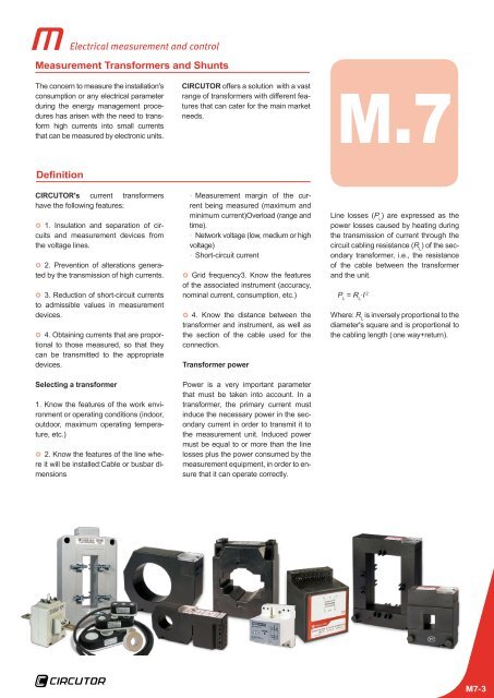
Electrical measurement and controlMeasurement Transformers and ShuntsThe concern to measure the installation'sconsumption or any electrical parameterduring the energy management procedureshas arisen with the need to transformhigh currents into small currentsthat can be measured by electronic units.CIRCUTOR offers a solution with a vastrange of <strong>transformers</strong> with different featuresthat can cater for the main marketneeds.M.7DefinitionCIRCUTOR's current <strong>transformers</strong>have the following features:}}1. Insulation and separation of circuitsand measurement devices fromthe voltage lines.}}2. Prevention of alterations generatedby the transmission of high currents.}}3. Reduction of short-circuit currentsto admissible values in measurementdevices.}}4. Obtaining currents that are proportionalto those measured, so that theycan be transmitted to the appropriatedevices.Selecting a transformer1. Know the features of the work environmentor operating conditions (indoor,outdoor, maximum operating temperature,etc.)}}2. Know the features of the line whereit will be installed:Cable or busbar dimensions• xMeasurement margin of the currentbeing measured (maximum andminimum current)Overload (range andtime).• xNetwork voltage (low, medium or highvoltage)• xShort-circuit current}}Grid frequency3. Know the featuresof the associated instrument (accuracy,nominal current, consumption, etc.)}}4. Know the distance between thetransformer and instrument, as well asthe section of the cable used for theconnection.Transformer powerPower is a very important parameterthat must be taken into account. In atransformer, the primary current mustinduce the necessary power in the secondarycurrent in order to transmit it tothe measurement unit. Induced powermust be equal to or more than the linelosses plus the power consumed by themeasurement equipment, in order to ensurethat it can operate correctly.Line losses (P L) are expressed as thepower losses caused by heating duringthe transmission of current through thecircuit cabling resistance (R L) of the secondarytransformer, i.e., the resistanceof the cable between the transformerand the unit.P L= R L·I 2Where: R Lis inversely proportional to thediameter's square and is proportional tothe cabling length ( one way+return).M7-3