Operational manual - Mercury
Operational manual - Mercury
Operational manual - Mercury
- No tags were found...

Create successful ePaper yourself
Turn your PDF publications into a flip-book with our unique Google optimized e-Paper software.
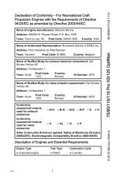
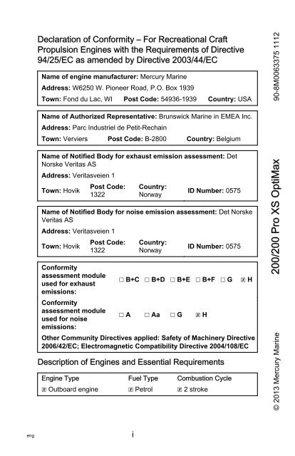
Declaration of Conformity – For Recreational CraftPropulsion Engines with the Requirements of Directive94/25/EC as amended by Directive 2003/44/ECName of engine manufacturer: <strong>Mercury</strong> MarineAddress: W6250 W. Pioneer Road, P.O. Box 1939Town: Fond du Lac, WI Post Code: 54936‐1939 Country: USAName of Authorized Representative: Brunswick Marine in EMEA Inc.Address: Parc Industriel de Petit‐RechainTown: Verviers Post Code: B‐2800 Country: BelgiumName of Notified Body for exhaust emission assessment: DetNorske Veritas ASAddress: Veritasveien 1Town: HovikPost Code:1322Country:NorwayID Number: 0575Name of Notified Body for noise emission assessment: Det NorskeVeritas ASAddress: Veritasveien 1Town: HovikPost Code:1322Conformityassessment moduleused for exhaustemissions:Conformityassessment moduleused for noiseemissions:Country:NorwayID Number: 0575☐ B+C ☐ B+D ☐ B+E ☐ B+F ☐ G ☒ H☐ A ☐ Aa ☐ G ☒ HOther Community Directives applied: Safety of Machinery Directive2006/42/EC; Electromagnetic Compatibility Directive 2004/108/ECDescription of Engines and Essential RequirementsEngine Type Fuel Type Combustion Cycle☒ Outboard engine ☒ Petrol ☒ 2 stroke© 2013 <strong>Mercury</strong> Marine 200/200 Pro XS OptiMax 90-8M0063375 1112eng i
Identification of Engines Covered by This Declaration ofConformityName of engine family1.5L OptiMax 75, 90, 115, 115Pro XS, 125 hp, 80 Jet2.5L OptiMax 135, 150, 150Pro XS, 175 hp3.0L OptiMax 200, 200 Pro XS,225 hpUnique engineidentificationnumber(s) or enginefamily code(s):starting serial numberModule HCertificate0B228000 RCD‐H‐2 Rev 40B228000 RCD‐H‐2 Rev 40B228000 RCD‐H‐2 Rev 4EssentialrequirementsStandardsAnnex 1.B—Exhaust EmissionsB.1 engineidentificationB.2 exhaustemissionrequirementsOthernormativedocument/methodTechnicalfile☐ ☐ ☒☒* ☐ ☐B.3 durability ☐ ☐ ☒B.4 owner's<strong>manual</strong>Annex 1.C—Noise EmissionsC.1 Noiseemission levelsC.2 Owner's<strong>manual</strong>Please specify inmore detail(* = mandatorystandard)* EN ISO8178‐1:1996☒ ☐ ☐ ISO 8665: 2006☒* ☐ ☐ EN ISO 14509☐ ☒ ☐ Owner's <strong>manual</strong>This declaration of conformity is issued under the sole responsibility of themanufacturer. I declare on behalf of the engine manufacturer that the enginesmentioned preceding complies with all applicable essential requirements inthe way specified.ii eng
Name / function:Mark D. Schwabero, President<strong>Mercury</strong> MarineDate and place of issue:September 04, 2012Fond du Lac, Wisconsin, USAWelcomeYou have selected one of the finest outboards available. Itincorporates numerous design features to ensure operating easeand durability.With proper care and maintenance, you will enjoy using thisproduct for many boating seasons. To ensure maximumperformance and carefree use, we ask that you thoroughly readthis <strong>manual</strong>.The Operation, Maintenance and Warranty Manual containsspecific instructions for using and maintaining your product. Wesuggest that this <strong>manual</strong> remain with the product for readyreference whenever you are on the water.Thank you for purchasing one of our products. We sincerelyhope your boating will be pleasant!<strong>Mercury</strong> MarineEPA Emissions RegulationsOutboards sold by <strong>Mercury</strong> Marine in the United States arecertified to the United States Environmental Protection Agencyas conforming to the requirements of the regulations for thecontrol of air pollution from new outboard motors. Thiscertification is contingent on certain adjustments being set tofactory standards. For this reason, the factory procedure forservicing the product must be strictly followed and, whereverpracticable, returned to the original intent of the design.Maintenance, replacement, or repair of the emission controldevices and systems may be performed by any marine enginerepair establishment or individual.eng iii
Engines are labeled with an emission control information decalas permanent evidence of EPA certification.! WARNINGThe engine exhaust from this product contains chemicalsknown to the state of California to cause cancer, birth defectsor other reproductive harm.Warranty MessageThe product you have purchased comes with a limited warrantyfrom <strong>Mercury</strong> Marine. The terms of the warranty are set forth inthe Warranty Information section of this <strong>manual</strong>. The warrantystatement contains a description of what is covered, what is notcovered, the duration of coverage, how to best obtain warrantycoverage, important disclaimers and limitations of damages, andother related information. Please review this information.The description and specifications contained herein were ineffect at the time this <strong>manual</strong> was approved for printing. <strong>Mercury</strong>Marine, whose policy is one of continued improvement, reservesthe right to discontinue models at any time, and to changespecifications, designs, methods, or procedures without noticeand without incurring obligation.<strong>Mercury</strong> Marine, Fond du Lac, Wisconsin U.S.A.Printed in the U.S.A.© 2013, <strong>Mercury</strong> MarineAlpha, Axius, Bravo One, Bravo Two, Bravo Three, Circle M withWaves Logo, K‐planes, Mariner, MerCathode, MerCruiser,<strong>Mercury</strong>, <strong>Mercury</strong> with Waves Logo, <strong>Mercury</strong> Marine, <strong>Mercury</strong>Precision Parts, <strong>Mercury</strong> Propellers, <strong>Mercury</strong> Racing,MotorGuide, OptiMax, Quicksilver, SeaCore, Skyhook,SmartCraft, Sport‐Jet, Verado, VesselView, Zero Effort, Zeus,and #1 On the Water are registered trademarks of BrunswickCorporation. <strong>Mercury</strong> Product Protection is a registered servicemark of Brunswick Corporation.iv eng
<strong>Mercury</strong> Premier Service<strong>Mercury</strong> evaluates the service performance of its dealers andassigns its highest rating of "<strong>Mercury</strong> Premier" to thosedemonstrating an exceptional commitment to service.Earning a <strong>Mercury</strong> Premier Service rating means a dealer:• Achieves a high 12‐month service Customer SatisfactionIndex (CSI) score for warranty service.• Possesses all of the necessary service tools, testequipment, <strong>manual</strong>s, and parts books.• Employs at least one certified or master technician.• Provides timely service for all <strong>Mercury</strong> Marine customers.• Offers extended service hours and mobile service, whenappropriate.• Uses, displays, and stocks an adequate inventory ofgenuine <strong>Mercury</strong> Precision Parts.• Offers a clean, neat shop with well‐organized tools andservice literature.eng v
vi eng
Warranty InformationWarranty Registration United States and Canada....................... 1Transfer of Warranty United States and Canada.........................1Transfer of <strong>Mercury</strong> Product Protection (Extended ServiceCoverage) Plan United States and Canada.................................2Outboard Limited Warranty..........................................................33 Year Limited Warranty Against Corrosion................................ 7Warranty Coverage and Exclusions.......................................... 11U.S. EPA Emissions Limited Warranty...................................... 13Emission Control System Components..................................... 13California Emissions Limited Warranty...................................... 14California Air Resources Board Explanation of Your CaliforniaEmission Control Warranty Statement.......................................18Emission Certification Star Label............................................... 19Warranty Policy—Australia and New Zealand........................... 20eng vii
General InformationBoater's Responsibilities............................................................ 27Before Operating Your Outboard............................................... 27Boat Horsepower Capacity........................................................ 28High‐Speed and High‐Performance Boat Operation................. 28Outboard Remote Control Models ............................................ 29Propeller Selection.....................................................................29Remote Steering Notice.............................................................32Lanyard Stop Switch.................................................................. 33Protecting People in the Water.................................................. 37Passenger Safety Message ‐ Pontoon Boats and Deck Boats................................................................................................... 38Wave and Wake Jumping.......................................................... 39Impact with Underwater Hazards...............................................40Exhaust Emissions.................................................................... 42Selecting Accessories for Your Outboard.................................. 44Safe Boating Recommendations............................................... 44Recording Serial Number.......................................................... 48200/200 Pro XS OptiMax Specifications.................................... 49Component Identification........................................................... 50TransportingTrailering Boat/Outboard .......................................................... 51viii eng
Fuel and OilFuel Recommendations............................................................. 52Oil Recommendation................................................................. 54Fuel Additives............................................................................ 54Fuel Requirements.................................................................... 54Avoiding Fuel Flow Restriction.................................................. 54Low Permeation Fuel Hose Requirement ................................. 54EPA Pressurized Portable Fuel Tank Requirements................. 55Fuel Demand Valve (FDV) Requirement................................... 55<strong>Mercury</strong> Marine's Pressurized Portable Fuel Tank.................... 55Filling Remote Oil Tank............................................................. 57Filling Engine Mounted Oil Reservoir Tank............................... 57Filling Fuel Tank........................................................................ 58Features and ControlsRemote Control Features.......................................................... 59Warning System........................................................................ 60Power Trim and Tilt....................................................................63OperationImportant Information.................................................................68Engine Break‐in......................................................................... 69Engine Break‐in Fuel Mixture.................................................... 70Prestarting Check List................................................................70Operating in Freezing Temperatures......................................... 70Operating in Saltwater or Polluted Water.................................. 71Operating at High Elevations..................................................... 71Effects of Elevation and Weather on Performance.................... 71Setting Trim Angle While Running Engine at Idle Speed.......... 72Operating in Shallow Water....................................................... 72Starting the Engine.................................................................... 73Gear Shifting.............................................................................. 76Stopping the Engine.................................................................. 77eng ix
MaintenancePower Package Care................................................................. 78Submerged Power Package...................................................... 78Replacement Parts for Your Power Package............................ 78EPA Emissions Regulations...................................................... 79Inspection and Maintenance Schedule...................................... 80Flushing the Cooling System (Powerhead)............................... 83Flushing the Cooling System (Lower Unit)................................ 84Top Cowl Removal and Installation........................................... 85Cleaning Care for Top Cowl...................................................... 85Alternator Belt Inspection...........................................................86Fuel System............................................................................... 86Steering Link Rod Fasteners..................................................... 89Fuses ........................................................................................ 91Corrosion Control Anode........................................................... 92Spark Plug Inspection and Replacement...................................92Battery Inspection ..................................................................... 94Charging System Fusible Link................................................... 95Propeller Replacement.............................................................. 95Air Compressor Filter................................................................. 99Lubrication Points.................................................................... 101Checking Power Trim Fluid......................................................104Gearcase Lubrication...............................................................105StorageStorage Preparation.................................................................108Fuel System............................................................................. 108Protecting Internal Engine Components.................................. 110Protecting External Outboard Components............................. 110Gearcase................................................................................. 111Positioning Outboard for Storage............................................ 111Battery Storage........................................................................ 111x eng
TroubleshootingStarter Motor Will Not Crank the Engine..................................112Engine Will Not Start................................................................112Engine Runs Erratically........................................................... 113Performance Loss....................................................................113Warning Horn Activates (With Power Loss).............................113Warning Horn Activates (No Power Loss)............................... 114Battery Will Not Hold Charge................................................... 114Owner Service AssistanceLocal Repair Service................................................................116Service Away from Home........................................................ 116Parts and Accessories Inquiries.............................................. 116Service Assistance.................................................................. 116Ordering Literature...................................................................119Outboard Installation<strong>Mercury</strong> Marine Validated Engine Mounting Hardware........... 121Boat Horsepower Capacity...................................................... 122Start in Gear Protection........................................................... 122Selecting Accessories for Your Outboard................................ 122Fuel System............................................................................. 123Installation Specifications........................................................ 125Lifting the Outboard................................................................. 125Steering Cable ‐ Starboard Side Routed Cable....................... 126Steering Link Rod Fasteners................................................... 127Determining Recommended Outboard Mounting Height......... 130Drilling Outboard Mounting Holes............................................ 131Fastening the Outboard to the Transom.................................. 132Electrical, Hoses, Control Cables, and Front Clamp............... 138Oil Injection Set‐Up.................................................................. 151Trim In Pin............................................................................... 154eng xi
Maintenance LogMaintenance Log..................................................................... 156xii eng
WARRANTY INFORMATIONWarranty Registration United States and CanadaTo be eligible for warranty coverage, the product must beregistered with <strong>Mercury</strong> Marine.At the time of sale, the selling dealer should complete thewarranty registration and immediately submit it to <strong>Mercury</strong>Marine via MercNET, e‐mail, or mail. Upon receipt of thiswarranty registration, <strong>Mercury</strong> Marine will record the registration.A copy of the warranty registration should be provided to you byyour selling dealer.NOTE: Registration lists must be maintained by <strong>Mercury</strong> Marineand any dealer of <strong>Mercury</strong> Marine products sold in the UnitedStates, should a safety recall notification under the FederalSafety Act be required.You may change your registered address at any time, includingat time of warranty claim, by calling <strong>Mercury</strong> Marine or sending aletter or fax with your name, old address, new address, andengine serial number to <strong>Mercury</strong> Marine’s warranty registrationdepartment. Your dealer can also process this change ofinformation.<strong>Mercury</strong> MarineAttn: Warranty Registration DepartmentW6250 W. Pioneer RoadP.O. Box 1939Fond du Lac, WI 54936-1939920-929-5054Fax +1 920 907 6663OUTSIDE UNITED STATES AND CANADAFor products purchased outside the United States and Canada,contact the distributor in your country, or the Marine PowerService Center closest to you.Transfer of Warranty United States and CanadaThe limited warranty is transferable to a subsequent purchaser,but only for the remainder of the unused portion of the limitedwarranty. This will not apply to products used for commercialapplications.eng 1
WARRANTY INFORMATIONTo transfer the warranty to the subsequent owner, send or fax acopy of the bill of sale or purchase agreement, new owner’sname, address, and engine serial number to <strong>Mercury</strong> Marine’swarranty registration department. In the United States andCanada, mail to:<strong>Mercury</strong> MarineAttn: Warranty Registration DepartmentW6250 W. Pioneer RoadP.O. Box 1939Fond du Lac, WI 54936-1939920-929-5054Fax +1 920 907 6663Upon processing the transfer of warranty, <strong>Mercury</strong> Marine willrecord the new owner's information.There is no charge for this service.OUTSIDE THE UNITED STATES AND CANADAFor products purchased outside the United States and Canada,contact the distributor in your country, or the Marine PowerService Center closest to you.Transfer of <strong>Mercury</strong> Product Protection (ExtendedService Coverage) Plan United States and CanadaThe remaining coverage period of the Product Protection Plan istransferable to the subsequent purchaser of the engine withinthirty (30) days from the date of sale. Contracts not transferredwithin thirty (30) days of the subsequent purchase will no longerbe valid and the product will no longer be eligible for coverageunder the terms of the contract.To transfer the plan to the subsequent owner, contact <strong>Mercury</strong>Product Protection or an authorized dealer to receive a Requestfor Transfer form. Submit to <strong>Mercury</strong> Product Protection areceipt/bill of sale, a completed Request of Transfer form, and acheck payable to <strong>Mercury</strong> Marine in the amount of $50.00 (perengine) to cover the transfer fee.Plan coverage is not transferable from one product to anotherproduct or for noneligible applications.The certified preowned engine plans are not transferable.2 eng
WARRANTY INFORMATIONFor help or assistance, contact <strong>Mercury</strong> Product ProtectionDepartment at 1‐888‐427‐5373 from 7:30 a.m. to 4:30 p.m. CST,Monday–Friday or e‐mail mpp_support@mercmarine.com.Outboard Limited WarrantyUNITED STATES, CANADA, EUROPE, MIDDLE EAST,AFRICA, AND THE CONFEDERATION OF INDEPENDENTSTATESWHAT IS COVERED: <strong>Mercury</strong> Marine warrants its new productsto be free of defects in material and workmanship during theperiod described below.DURATION OF COVERAGE: This Limited Warranty providescoverage for three (3) years from the date the product is first soldto a recreational use retail purchaser, or the date on which theproduct is first put into service, whichever occurs first.Commercial users of these products receive warranty coverageof one (1) year from the date of first retail sale, or one (1) yearfrom the date on which the product was first put into service,whichever occurs first. Commercial use is defined as any work oremployment related use of the product, or any use of the productwhich generates income, for any part of the warranty period,even if the product is only occasionally used for such purposes.The repair or replacement of parts, or the performance of serviceunder this warranty, does not extend the life of this warrantybeyond its original expiration date. Unexpired warranty coveragecan be transferred from one recreational use customer to asubsequent recreational use customer upon proper reregistrationof the product. Unexpired warranty coverage cannot betransferred either to or from a commercial use customer.Warranty coverage may be terminated for used repossessedproduct; or product purchased at auction, from a salvage yard, orfrom an insurance company.eng 3
WARRANTY INFORMATIONCONDITIONS THAT MUST BE MET IN ORDER TO OBTAINWARRANTY COVERAGE: Warranty coverage is available onlyto retail customers that purchase from a Dealer authorized by<strong>Mercury</strong> Marine to distribute the product in the country in whichthe sale occurred, and then only after the <strong>Mercury</strong> Marinespecified predelivery inspection process is completed anddocumented. Warranty coverage becomes available upon properregistration of the product by the authorized dealer. Inaccuratewarranty registration information regarding recreational use, orsubsequent change of use from recreational to commercial(unless properly reregistered) may void the warranty at the solediscretion of <strong>Mercury</strong> Marine. Routine maintenance outlined inthe Operation and Maintenance Manual must be timelyperformed in order to maintain warranty coverage. <strong>Mercury</strong>Marine reserves the right to make warranty coverage contingentupon proof of proper maintenance.WHAT MERCURY WILL DO: <strong>Mercury</strong>'s sole and exclusiveobligation under this warranty is limited to, at our option,repairing a defective part, replacing such part or parts with newor <strong>Mercury</strong> Marine certified remanufactured parts, or refundingthe purchase price of the <strong>Mercury</strong> product. <strong>Mercury</strong> reserves theright to improve or modify products from time to time withoutassuming an obligation to modify products previouslymanufactured.4 eng
WARRANTY INFORMATIONHOW TO OBTAIN WARRANTY COVERAGE: The customermust provide <strong>Mercury</strong> with a reasonable opportunity to repair,and reasonable access to the product for warranty service.Warranty claims shall be made by delivering the product forinspection to a <strong>Mercury</strong> dealer authorized to service the product.If purchaser cannot deliver the product to such a dealer, writtennotice must be given to <strong>Mercury</strong>. We will then arrange for theinspection and any covered repair. Purchaser, in that case, shallpay for all related transportation charges and/or travel time. If theservice provided is not covered by this warranty, purchaser shallpay for all related labor and material, and any other expensesassociated with that service. Purchaser shall not, unlessrequested by <strong>Mercury</strong>, ship the product or parts of the productdirectly to <strong>Mercury</strong>. Proof of registered ownership must bepresented to the dealer at the time warranty service is requestedin order to obtain coverage.eng 5
WARRANTY INFORMATIONWHAT IS NOT COVERED: This limited warranty does not coverroutine maintenance items, tune‐ups, adjustments, normal wearand tear, damage caused by abuse, abnormal use, use of apropeller or gear ratio that does not allow the engine to run in itsrecommended wide‐open throttle RPM range (see the Operationand Maintenance Manual), operation of the product in a mannerinconsistent with the recommended operation/duty cycle sectionof the Operation and Maintenance Manual, neglect, accident,submersion, improper installation (proper installationspecifications and techniques are set forth in the installationinstructions for the product), improper service, use of anaccessory or part not manufactured or sold by us, jet pumpimpellers and liners, operation with fuels, oils or lubricants whichare not suitable for use with the product (see the Operation andMaintenance Manual), alteration or removal of parts, waterentering the engine through the fuel intake, air intake or exhaustsystem, or damage to the product from insufficient cooling watercaused by blockage of the cooling system by a foreign body,running the engine out of water, mounting the engine too high onthe transom, or running the boat with the engine trimmed out toofar. Use of the product for racing or other competitive activity, oroperating with a racing type lower unit, at any point, even by aprior owner of the product, voids the warranty.Expenses related to haul‐out, launch, towing, storage, telephone,rental, inconvenience, slip fees, insurance coverage, loanpayments, loss of time, loss of income, or any other type ofincidental or consequential damages are not covered by thiswarranty. Also, expenses associated with the removal and/orreplacement of boat partitions or material caused by boat designfor access to the product are not covered by this warranty.No individual or entity, including <strong>Mercury</strong> Marine authorizeddealers, has been given authority by <strong>Mercury</strong> Marine to makeany affirmation, representation or warranty regarding theproduct, other than those contained in this limited warranty, andif made, shall not be enforceable against <strong>Mercury</strong> Marine.6 eng
WARRANTY INFORMATIONFor additional information regarding events and circumstancescovered by this warranty, and those that are not, see theWarranty Coverage section of the Operation and MaintenanceManual, incorporated by reference into this warranty.DISCLAIMERS AND LIMITATIONS:THE IMPLIED WARRANTIES OF MERCHANTABILITY AND FITNESS FORA PARTICULAR PURPOSE ARE EXPRESSLY DISCLAIMED. TO THEEXTENT THAT THEY CANNOT BE DISCLAIMED, THE IMPLIEDWARRANTIES ARE LIMITED IN DURATION TO THE LIFE OF THEEXPRESS WARRANTY. INCIDENTAL AND CONSEQUENTIAL DAMAGESARE EXCLUDED FROM COVERAGE UNDER THIS WARRANTY. SOMESTATES/COUNTRIES DO NOT ALLOW FOR THE DISCLAIMERS,LIMITATIONS AND EXCLUSIONS IDENTIFIED ABOVE, AS A RESULT,THEY MAY NOT APPLY TO YOU. THIS WARRANTY GIVES YOUSPECIFIC LEGAL RIGHTS, AND YOU MAY ALSO HAVE OTHER LEGALRIGHTS WHICH VARY FROM STATE TO STATE AND COUNTRY TOCOUNTRY.3 Year Limited Warranty Against CorrosionWHAT IS COVERED: <strong>Mercury</strong> Marine warrants that each new<strong>Mercury</strong>, Mariner, <strong>Mercury</strong> Racing, Sport‐Jet, M 2 Jet Drive,Tracker by <strong>Mercury</strong> Marine Outboard, <strong>Mercury</strong> MerCruiserInboard or Sterndrive Engine (Product) will not be renderedinoperative as a direct result of corrosion for the period of timedescribed below.DURATION OF COVERAGE: This limited corrosion warrantyprovides coverage for three (3) years from either the date theproduct is first sold, or the date on which the product is first putinto service, whichever occurs first. The repair or replacement ofparts, or the performance of service under this warranty, doesnot extend the life of this warranty beyond its original expirationdate. Unexpired warranty coverage can be transferred tosubsequent (noncommercial use) purchaser upon properreregistration of the product.eng 7
WARRANTY INFORMATIONCONDITIONS THAT MUST BE MET IN ORDER TO OBTAINWARRANTY COVERAGE: Warranty coverage is available onlyto retail customers that purchase from a Dealer authorized by<strong>Mercury</strong> Marine to distribute the product in the country in whichthe sale occurred, and then only after the <strong>Mercury</strong> Marinespecified predelivery inspection process is completed anddocumented. Warranty coverage becomes available upon properregistration of the product by the authorized dealer. Corrosionprevention devices specified in the Operation and MaintenanceManual must be in use on the boat, and routine maintenanceoutlined in the Operation and Maintenance Manual must betimely performed (including, without limitation, the replacement ofsacrificial anodes, use of specified lubricants, and touch‐up ofnicks and scratches) in order to maintain warranty coverage.<strong>Mercury</strong> Marine reserves the right to make warranty coveragecontingent upon proof of proper maintenance.WHAT MERCURY WILL DO: <strong>Mercury</strong>'s sole and exclusiveobligation under this warranty is limited to, at our option,repairing a corroded part, replacing such part or parts with newor <strong>Mercury</strong> Marine certified remanufactured parts, or refundingthe purchase price of the <strong>Mercury</strong> product. <strong>Mercury</strong> reserves theright to improve or modify products from time to time withoutassuming an obligation to modify products previouslymanufactured.8 eng
WARRANTY INFORMATIONHOW TO OBTAIN WARRANTY COVERAGE: The customermust provide <strong>Mercury</strong> with a reasonable opportunity to repair,and reasonable access to the product for warranty service.Warranty claims shall be made by delivering the product forinspection to a <strong>Mercury</strong> dealer authorized to service the product.If purchaser cannot deliver the product to such a dealer, writtennotice must be given to <strong>Mercury</strong>. We will then arrange for theinspection and any covered repair. Purchaser, in that case, shallpay for all related transportation charges and/or travel time. If theservice provided is not covered by this warranty, purchaser shallpay for all related labor and material, and any other expensesassociated with that service. Purchaser shall not, unlessrequested by <strong>Mercury</strong>, ship the product or parts of the productdirectly to <strong>Mercury</strong>. Proof of registered ownership must bepresented to the dealer at the time warranty service is requestedin order to obtain coverage.WHAT IS NOT COVERED: This limited warranty does not coverelectrical system corrosion; corrosion resulting from damage,corrosion which causes purely cosmetic damage, abuse, orimproper service; corrosion to accessories, instruments, steeringsystems; corrosion to factory installed jet drive unit; damage dueto marine growth; product sold with less than a one year limitedProduct warranty; replacement parts (parts purchased bycustomer); products used in a commercial application.Commercial use is defined as any work or employment relateduse of the product, or any use of the product which generatesincome, for any part of the warranty period, even if the product isonly occasionally used for such purposes.eng 9
WARRANTY INFORMATIONCorrosion damage caused by stray electrical currents (onshorepower connections, nearby boats, submerged metal) is notcovered by this corrosion warranty and should be protectedagainst by the use of a corrosion protection system, such as the<strong>Mercury</strong> Precision Parts or Quicksilver MerCathode systemand/or Galvanic Isolator. Corrosion damage caused by improperapplication of copper base antifouling paints is also not coveredby this limited warranty. If antifouling protection is required,Tri‐Butyl‐Tin‐Adipate (TBTA) base antifouling paints arerecommended on Outboard and MerCruiser boating applications.In areas where TBTA base paints are prohibited by law, copperbase paints can be used on the hull and transom. Do not applypaint to the outboard or MerCruiser product. In addition, caremust be taken to avoid an electrical interconnection between thewarranted product and the paint. For MerCruiser product, anunpainted gap of at least 38 mm (1.5 in.) should be left aroundthe transom assembly. Refer to the Operation and MaintenanceManual for additional details.For additional information regarding events and circumstancescovered by this warranty, and those that are not, see theWarranty Coverage section of the Operation and MaintenanceManual, incorporated by reference into this warranty.DISCLAIMERS AND LIMITATIONS:THE IMPLIED WARRANTIES OF MERCHANTABILITY AND FITNESS FORA PARTICULAR PURPOSE ARE EXPRESSLY DISCLAIMED. TO THEEXTENT THAT THEY CANNOT BE DISCLAIMED, THE IMPLIEDWARRANTIES ARE LIMITED IN DURATION TO THE LIFE OF THEEXPRESS WARRANTY. INCIDENTAL AND CONSEQUENTIAL DAMAGESARE EXCLUDED FROM COVERAGE UNDER THIS WARRANTY. SOMESTATES/COUNTRIES DO NOT ALLOW FOR THE DISCLAIMERS,LIMITATIONS AND EXCLUSIONS IDENTIFIED ABOVE, AS A RESULT,THEY MAY NOT APPLY TO YOU. THIS WARRANTY GIVES YOUSPECIFIC LEGAL RIGHTS, AND YOU MAY ALSO HAVE OTHER LEGALRIGHTS WHICH VARY FROM STATE TO STATE AND COUNTRY TOCOUNTRY.10 eng
WARRANTY INFORMATIONWarranty Coverage and ExclusionsThe purpose of this section is to help eliminate some of the morecommon misunderstandings regarding warranty coverage. Thefollowing information explains some of the types of services thatare not covered by warranty. The provisions set forth followinghave been incorporated by reference into the Three Year LimitedWarranty Against Corrosion Failure, the International LimitedOutboard Warranty, and the United States and Canada LimitedOutboard Warranty.Keep in mind that warranty covers repairs that are needed withinthe warranty period because of defects in material andworkmanship. Installation errors, accidents, normal wear, and avariety of other causes that affect the product are not covered.Warranty is limited to defects in material or workmanship, butonly when the consumer sale is made in the country to whichdistribution is authorized by us.Should you have any questions concerning warranty coverage,contact your authorized dealer. They will be pleased to answerany questions that you may have.GENERAL EXCLUSIONS FROM WARRANTY1. Minor adjustments and tune‐ups, including checking,cleaning, or adjusting spark plugs, ignition components,carburetor settings, filters, belts, controls, and checkinglubrication made in connection with normal services.2. Factory installed jet drive units ‐ Specific parts excludedfrom the warranty are: the jet drive impeller and jet driveliner damaged by impact or wear, and water damageddriveshaft bearings as a result of improper maintenance.3. Damage caused by neglect, lack of maintenance, accident,abnormal operation, or improper installation or service.4. Haul‐out, launch, towing charges, removal and/orreplacement of boat partitions or material because of boatdesign for necessary access to the product, all relatedtransportation charges and/or travel time, etc. Reasonableaccess must be provided to the product for warranty service.Customer must deliver product to an authorized dealer.eng 11
WARRANTY INFORMATION5. Additional service work requested by customer other thanthat necessary to satisfy the warranty obligation.6. Labor performed by other than an authorized dealer may becovered only under the following circumstances: whenperformed on emergency basis (providing there are noauthorized dealers in the area who can perform the workrequired or have no facilities to haul‐out, etc., and priorfactory approval has been given to have the work performedat this facility).7. All incidental and/or consequential damages (storagecharges, telephone or rental charges of any type,inconvenience or loss of time or income) are the owner'sresponsibility.8. Use of other than <strong>Mercury</strong> Precision or Quicksilver partswhen making warranty repairs.9. Oils, lubricants, or fluids changed as a matter of normalmaintenance is customer's responsibility unless loss orcontamination of same is caused by product failure thatwould be eligible for warranty consideration.10.Participating in or preparing for racing or other competitiveactivity or operating with a racing type lower unit.11.Engine noise does not necessarily indicate a serious engineproblem. If diagnosis indicates a serious internal enginecondition which could result in a failure, conditionresponsible for noise should be corrected under thewarranty.12.Lower unit and/or propeller damage caused by striking asubmerged object is considered a marine hazard.13.Water entering engine through the fuel intake, air intake, orexhaust system or submersion.14.Failure of any parts caused by lack of cooling water, whichresults from starting motor out of water, foreign materialblocking inlet holes, motor being mounted too high, ortrimmed too far out.15.Use of fuels and lubricants which are not suitable for usewith or on the product. Refer to the Maintenance section.12 eng
WARRANTY INFORMATION16.Our limited warranty does not apply to any damage to ourproducts caused by the installation or use of parts andaccessories which are not manufactured or sold by us.Failures which are not related to the use of those parts oraccessories are covered under warranty if they otherwisemeet the terms of the limited warranty for that product.U.S. EPA Emissions Limited WarrantyConsistent with the obligations created by 40 CFR Part 1045,Subpart B, <strong>Mercury</strong> Marine provides a five year or 175 hours ofengine use, whichever occurs first, to the retail customer, thatthe engine is designed, built, and equipped so as to conform atthe time of sale with applicable regulations under section 213 ofthe Clean Air Act, and that the engine is free from defects inmaterials and workmanship which cause the engine to fail toconform with applicable regulations. This emission‐relatedwarranty covers all the components listed in the EmissionControl System Components.Emission Control System ComponentsThe EPA and California emission‐related warranty covers all thefollowing list of components:COMPONENTS OF THE EMISSIONS CONTROL SYSTEM:1. Fuel metering systema. Carburetor and internal parts (and/or pressure regulatoror fuel injection system)b. Cold start enrichment systemc. Intake valves2. Air induction systema. Intake manifoldb. Turbocharger or supercharger systems (whereapplicable)3. Ignition systema. Spark plugsb. Magneto or electronic ignition systemc. Spark advance/retard systemeng 13
WARRANTY INFORMATIONd. Ignition coil and/or control modulee. Ignition wires4. Lubrication system (4‐Stroke engines excluded)a. Oil pump and internal partsb. Oil injectorsc. Oil meter5. Exhaust systema. Exhaust manifoldb. Exhaust valves6. Miscellaneous items used in above systemsa. Hoses, clamps, fittings, tubing, sealing gaskets ordevices, and mounting hardwareb. Pulleys, belts, and idlersc. Vacuum, temperature, check and time sensitive valvesand switchesd. Electronic controlsThe emission‐related warranty does not cover componentswhose failure would not increase an engine's emissions on anyregulated pollutant.California Emissions Limited WarrantyThe California Air Resources Board has promulgated airemission regulations for outboard engines. The regulations applyto all outboard engines sold to retail consumers in California, andwhich were manufactured for the 2001 model year and later.<strong>Mercury</strong> Marine, in compliance with those regulations, providesthis limited warranty for the emission control systems (see thecomponents listed in the Emission Control SystemComponents), and further warrants that the outboard enginewas designed, built, and equipped to conform with all applicableregulations adopted by the California Air Resources Boardpursuant to its authority in Chapters 1 and 2, Part 5, Division 26of the Health and Safety Code. For information regarding thelimited warranty for the nonemission‐related components of theoutboard, please see the limited warranty statement for youroutboard.14 eng
WARRANTY INFORMATIONWHAT IS COVERED: <strong>Mercury</strong> Marine warrants the componentsof the emissions control systems (see the components listed inthe Emission Control System Components) of its new, 2001model year and later outboards, sold by a California dealer toretail customers residing in California, to be free from defects inmaterial or workmanship, that cause the failure of a warrantedpart to be identical in all material respects to that part asdescribed in the application of <strong>Mercury</strong> Marine for certificationfrom the California Air Resources Board, for the period of time,and under the conditions, identified below. The cost to diagnosea warranty failure is covered under the warranty (if the warrantyclaim is approved). Damage to other engine components causedby the failure of a warranted part will also be repaired underwarranty.DURATION OF COVERAGE: This limited warranty providescoverage for the components of the emissions control systems ofnew, 2001 model year and later outboards, sold to retailcustomers in California for four (4) years from either the date theproduct is first sold, or first put into service, whichever occursfirst, or the accumulation of 250 hours of engine operation (asdetermined by the engine's hour meter, if any). Emission‐relatednormal maintenance items such as spark plugs and filters, thatare on the warranted parts list, are warranted up to their firstrequired replacement interval only. Refer to Emission ControlSystem Components and Maintenance Schedule. The repair orreplacement of parts, or the performance of service under thiswarranty, does not extend the life of this warranty beyond itsoriginal expiration date. Unexpired warranty coverage can betransferred to a subsequent purchaser. (See instructions ontransfer of warranty.)eng 15
WARRANTY INFORMATIONHOW TO OBTAIN WARRANTY COVERAGE: The customermust provide <strong>Mercury</strong> with a reasonable opportunity to repairand reasonable access to the product for warranty service.Warranty claims shall be made by delivering the product forinspection to a <strong>Mercury</strong> dealer authorized to service the product.If purchaser cannot deliver the product to such a dealer, pleasenotify <strong>Mercury</strong> Marine and <strong>Mercury</strong> will then arrange for theinspection and any covered repair. Purchaser, in that case, shallpay for all related transportation charges and/or travel time. If theservice provided is not covered by this warranty, purchaser shallpay for all related labor and material, and any other expensesassociated with that service. Purchaser shall not, unlessrequested by <strong>Mercury</strong>, ship the product or parts of the productdirectly to <strong>Mercury</strong>.WHAT MERCURY WILL DO: <strong>Mercury</strong> Marine's sole andexclusive obligation under this warranty is limited to, at ourexpense and at our option, repairing or replacing defective partswith new or <strong>Mercury</strong> Marine certified remanufactured parts, orrefunding the purchase price of the <strong>Mercury</strong> product. <strong>Mercury</strong>reserves the right to improve or modify products from time totime without assuming an obligation to modify productspreviously manufactured.WHAT IS NOT COVERED: This limited warranty does not coverroutine maintenance items, tune‐ups, adjustments, normal wearand tear, damage caused by abuse, abnormal use, use of apropeller or gear ratio that does not allow the engine to run in itsrecommended wide‐open throttle RPM range (see GeneralInformation ‐ Specifications), operation of the product in amanner inconsistent with the recommended operationprocedures, neglect, accident, submersion, improper installation(proper installation specifications and techniques are set forth inthe installation instructions for the product), improper service, jetpump impellers and liners, operation with fuels, oils, or lubricantswhich are not suitable for use with the product (see Fuel andOil), alteration or removal of parts.16 eng
WARRANTY INFORMATIONExpenses related to haul‐out, launch, towing, storage, telephone,rental, inconvenience, slip fees, insurance coverage, loanpayments, loss of time, loss of income, or any other type ofincidental or consequential damages are not covered by thiswarranty. Also, expenses associated with the removal and/orreplacement of boat partitions or material caused by boat designfor access to the product are not covered by this warranty.Nonwarranty maintenance, replacement, or repair of emissioncontrol devices and systems may be performed by any marineengine repair establishment or individual. The use ofnon‐<strong>Mercury</strong> parts for nonwarranty maintenance or repairs willnot be grounds for disallowing other warranty work. The use ofadd‐on (as defined at section 1900 (b)(1) and (b)(10) of Title 13of the California Code of Regulations) or modified parts notexempted by the California Air Resources Board may begrounds for disallowing a warranty claim, at the discretion of<strong>Mercury</strong> Marine. Failures of warranted parts caused by the useof a nonexempted add‐on or modified part will not be covered.DISCLAIMERS AND LIMITATIONSTHE IMPLIED WARRANTIES OF MERCHANTABILITY AND FITNESS FORA PARTICULAR PURPOSE ARE EXPRESSLY DISCLAIMED. TO THEEXTENT THAT THEY CANNOT BE DISCLAIMED, THE IMPLIEDWARRANTIES ARE LIMITED IN DURATION TO THE LIFE OF THEEXPRESS WARRANTY. INCIDENTAL AND CONSEQUENTIAL DAMAGESARE EXCLUDED FROM COVERAGE UNDER THIS WARRANTY. SOMESTATES/COUNTRIES DO NOT ALLOW FOR THE DISCLAIMERS,LIMITATIONS AND EXCLUSIONS IDENTIFIED ABOVE, AS A RESULT,THEY MAY NOT APPLY TO YOU. THIS WARRANTY GIVES YOUSPECIFIC LEGAL RIGHTS, AND YOU MAY ALSO HAVE OTHER LEGALRIGHTS WHICH VARY FROM STATE TO STATE AND COUNTRY TOCOUNTRY.If you have any questions regarding your warranty rights andresponsibilities, you should contact <strong>Mercury</strong> Marine at1‐920‐929‐5040.eng 17
WARRANTY INFORMATIONAs the outboard engine owner, you should, however, be awarethat <strong>Mercury</strong> Marine may deny you warranty coverage if youroutboard engine or a part has failed due to abuse, neglect,improper maintenance, or unapproved modifications.You are responsible for presenting your outboard to a <strong>Mercury</strong>dealer authorized to service the product as soon as a problemexists. The warranty repairs will be completed in a reasonableamount of time, not to exceed 30 days.If you have any questions regarding your warranty rights andresponsibilities, you should contact <strong>Mercury</strong> Marine at1‐920‐929‐5040.Emission Certification Star LabelOutboards are labeled on the cowl with one of the following starlabels.The symbol for a cleaner marine engine means:Cleaner air and water ‐ for a healthier lifestyle and environment.Better fuel economy ‐ burns up to 30–40 percent less gas and oilthan conventional carbureted two‐stroke engines, saving moneyand resources.Longer emission warranty ‐ protects consumer for worry‐freeoperation.One Star ‐ Low Emission22531The One Star label identifies engines that meetthe Air Resources Board's 2001 exhaustemissions standards. Engines meeting thesestandards have 75% lower emissions thanconventional carbureted two‐stroke engines.These engines are equivalent to the U.S. EPA's2006 standards for marine engines.Two Stars ‐ Very Low Emission42537The Two Star label identifies engines that meetthe Air Resources Board's Personal Watercraftand Outboard marine engine 2004 exhaustemissions standards. Engines meeting thesestandards have 20% lower emissions than OneStar ‐ Low Emission engines.eng 19
WARRANTY INFORMATIONThree Stars ‐ Ultra Low Emission42538The Three Star label identifies engines that meetthe Air Resources Board's Personal Watercraftand Outboard marine engine 2008 exhaustemissions standards or the Sterndrive andInboard marine engine 2003‐2008 exhaustemission standards. Engines meeting thesestandards have 65% lower emissions than OneStar ‐ Low Emission engines.Four Stars ‐ Super Ultra Low Emission42539The Four Star label identifies engines that meetthe Air Resources Board's Sterndrive and Inboardmarine engine 2009 exhaust emission standards.Personal Watercraft and Outboard marine enginesmay also comply with these standards. Enginesmeeting these standards have 90% loweremissions than One Star ‐ Low Emission engines.Warranty Policy—Australia and New ZealandMERCURY/MARINER OUTBOARD LIMITED WARRANTY–AUSTRALIA AND NEW ZEALAND POLICYThis limited warranty is given by Marine Power International PtyLtd ACN 003 100 007 of 41–71 Bessemer Drive, DandenongSouth, Victoria 3175 Australia (telephone (61) (3) 9791 5822)e‐mail: merc_info@mercmarine.com.What is Covered<strong>Mercury</strong> Marine warrants its new products to be free of defects inmaterial and workmanship during the period described below.The benefits to the consumer given by the warranty are inaddition to other rights and remedies of the consumer under alaw in relation to the goods or services to which the warrantyrelates.20 eng
WARRANTY INFORMATIONGuarantees Under Australian Consumer LawOur goods come with guarantees that cannot be excluded underthe Australian Consumer Law. You are entitled to a replacementor refund for a major failure and compensation for any otherreasonably foreseeable loss or damage. You are also entitled tohave the goods repaired or replaced if the goods fail to be ofacceptable quality and the failure does not amount to a majorfailure.Warranty Period for Recreational UseThis Limited Warranty provides coverage for three (3) years fromthe date the product is first sold to a recreational use retailpurchaser, or the date on which the product is first put intoservice, whichever occurs first. Unexpired warranty coveragecan be transferred to a subsequent recreational use customerupon proper registration of the product.Warranty Period for Commercial UseCommercial users of these products receive warranty coverageunder this Limited Warranty of one (1) year from the date of firstretail sale, or one (1) year from the date on which the productwas first put into service, whichever occurs first. Commercial useis defined as any work or employment related use of the product,or any use of the product which generates income, for any partof the warranty period, even if the product is only occasionallyused for such purposes. Unexpired warranty coverage cannot betransferred either to or from a commercial use customer.eng 21
WARRANTY INFORMATIONConditions That Must Be Met to Obtain Warranty CoverageWarranty coverage under this Limited Warranty is available onlyto retail customers that purchase from a Dealer authorized by<strong>Mercury</strong> Marine to distribute the product in the country in whichthe sale occurred, and then only after the <strong>Mercury</strong> Marinespecified predelivery inspection process is completed anddocumented. Warranty coverage becomes available upon properregistration of the product by the authorized dealer. Inaccuratewarranty registration information regarding recreational use, orsubsequent change of use from recreational to commercial(unless properly registered) may void the warranty at the solediscretion of <strong>Mercury</strong> Marine. Routine maintenance outlined inthe Operation and Maintenance Manual must be timelyperformed in order to maintain warranty coverage. <strong>Mercury</strong>Marine reserves the right to make warranty coverage contingentupon proof of proper maintenance.What <strong>Mercury</strong> Will Do<strong>Mercury</strong> Marine's sole and exclusive obligation under thisLimited Warranty is limited to, at our option, repairing a defectivepart, replacing such part or parts with new or <strong>Mercury</strong> Marinecertified remanufactured parts, or refunding the purchase price ofthe <strong>Mercury</strong> Marine product. <strong>Mercury</strong> Marine reserves the rightto improve or modify products from time to time withoutassuming an obligation to modify products previouslymanufactured.22 eng
WARRANTY INFORMATIONHow to Obtain Warranty Coverage Under This Limited WarrantyThe customer must provide <strong>Mercury</strong> Marine with a reasonableopportunity to repair and reasonable access to the product forwarranty service. Warranty claims shall be made by deliveringthe product for inspection to a <strong>Mercury</strong> Marine dealer authorizedto service the product. A list of dealers and their contact details isavailable at www.mercurymarine.com.au. If the purchaser cannotdeliver the product to such a dealer, written notice must be givento <strong>Mercury</strong> Marine at the address shown above. <strong>Mercury</strong> Marinewill then arrange for the inspection and any covered repair. ThisLimited Warranty will not cover the purchaser for all relatedtransportation charges and travel time. If the service provided isnot covered by this limited warranty, the purchaser shall pay forall related labor and material and any other expenses associatedwith that service, provided that a consumer will not be obligatedto pay where the service has been carried out to remedy a failureof an acceptable quality guarantee which is binding on <strong>Mercury</strong>Marine under the Australian Consumer Law. The purchaser shallnot, unless requested by <strong>Mercury</strong> Marine, ship the product orparts of the product directly to <strong>Mercury</strong> Marine. Proof ofregistered ownership must be presented to the dealer at the timewarranty service is requested in order to obtain coverage underthis Limited Warranty.eng 23
What is Not CoveredWARRANTY INFORMATIONThis limited warranty does not cover routine maintenance items,tune‐ups, adjustments, normal wear and tear, damage causedby abuse, abnormal use, use of a propeller or gear ratio thatdoes not allow the engine to run in its recommended wide‐openthrottle RPM range (see the Operation and MaintenanceManual), operation of the product in a manner inconsistent withthe recommended operation/duty cycle section of the Operationand Maintenance Manual, neglect, accident, submersion,improper installation (proper installation specifications andtechniques are set forth in the installation instructions for theproduct), improper service, use of an accessory or part notmanufactured or sold by us, jet pump impellers and liners,operation with fuels, oils or lubricants which are not suitable foruse with the product (see the Operation and MaintenanceManual), alteration or removal of parts, water entering the enginethrough the fuel intake, air intake or exhaust system, or damageto the product from insufficient cooling water caused by blockageof the cooling system by a foreign body, running the engine outof water, mounting the engine too high on the transom, orrunning the boat with the engine trimmed out too far. Use of theproduct for racing or other competitive activity, or operating witha racing type lower unit, at any point, even by a prior owner ofthe product, voids the warranty.Expenses related to haul‐out, launch, towing, storage, telephone,rental, inconvenience, slip fees, insurance coverage, loanpayments, loss of time, loss of income, or any other type ofincidental or consequential damages are not covered by thisLimited Warranty. Also, expenses associated with the removaland/or replacement of boat partitions or material caused by boatdesign for access to the product are not covered by thiswarranty.24 eng
WARRANTY INFORMATIONNo individual or entity, including <strong>Mercury</strong> Marine authorizeddealers, has been given authority by <strong>Mercury</strong> Marine to makeany affirmation, representation or warranty regarding theproduct, other than those contained in this limited warranty, andif made, shall not be enforceable against <strong>Mercury</strong> Marine. Foradditional information regarding events and circumstancescovered by this warranty, and those that are not, see theWarranty Coverage section of the Operation and MaintenanceManual, incorporated by reference into this warranty.Expense of Claiming This Limited WarrantyThis Limited Warranty does not cover any expenses you mayincur claiming the warranty.DISCLAIMERS AND LIMITATIONS:EXCEPT FOR APPLICABLE GUARANTEES AND OTHER RIGHTS ANDREMEDIES THAT A CONSUMER MAY HAVE UNDER THE AUSTRALIANCONSUMER LAW OR OTHER LAW IN RELATION TO WHICH THEPRODUCTS RELATE, THE IMPLIED WARRANTIES OFMERCHANTABILITY AND FITNESS FOR A PARTICULAR PURPOSE AREEXPRESSLY DISCLAIMED. TO THE EXTENT THAT THEY CANNOT BEDISCLAIMED, THE IMPLIED WARRANTIES ARE LIMITED IN DURATIONTO THE LIFE OF THE EXPRESS WARRANTY. INCIDENTAL ANDCONSEQUENTIAL DAMAGES ARE EXCLUDED FROM COVERAGEUNDER THIS LIMITED WARRANTY.TRANSFER OF WARRANTY—AUSTRALIA AND NEWZEALAND POLICYThe limited warranty is transferable to a subsequent purchaser,but only for the remainder of the unused portion of the limitedwarranty. This will not apply to products used for commercialapplications.To transfer the warranty to the subsequent owner, send or fax acopy of the Bill of Sale or Purchase Agreement, new owner’sname, address, and hull identification number (HIN) to <strong>Mercury</strong>Marine’s Warranty Registration Department. In Australia andNew Zealand, mail to:eng 25
<strong>Mercury</strong> MarineWARRANTY INFORMATIONAttn: Warranty Registration DepartmentBrunswick Asia Pacific GroupPrivate Bag 1420Dandenong South, Victoria 3164AustraliaUpon processing the transfer of warranty, <strong>Mercury</strong> Marine willsend registration verification to the new owner of the product bymail. There is no charge for this service.You may change your address at any time, including at the timeof the warranty claim, by calling <strong>Mercury</strong> Marine or sending aletter or fax with your name, old address, new address, and hullidentification number (HIN) to <strong>Mercury</strong> Marine’s WarrantyRegistration Department.26 eng
GENERAL INFORMATIONBoater's ResponsibilitiesThe operator (driver) is responsible for the correct and safeoperation of the boat and the safety of its occupants and generalpublic. It is strongly recommended that each operator read andunderstand this entire <strong>manual</strong> before operating the outboard.Be sure that at least one additional person onboard is instructedin the basics of starting and operating the outboard and boathandling in case the driver is unable to operate the boat.Before Operating Your OutboardRead this <strong>manual</strong> carefully. Learn how to operate your outboardproperly. If you have any questions, contact your dealer.Safety and operating information that is practiced, along withusing good common sense, can help prevent personal injury andproduct damage.This <strong>manual</strong> as well as safety labels posted on the outboard usethe following safety alerts to draw your attention to special safetyinstructions that should be followed.! DANGERIndicates a hazardous situation which, if not avoided, will resultin death or serious injury.! WARNINGIndicates a hazardous situation which, if not avoided, couldresult in death or serious injury.! CAUTIONIndicates a hazardous situation which, if not avoided, couldresult in minor or moderate injury.NOTICEIndicates a situation which, if not avoided, could result inengine or major component failure.eng 27
GENERAL INFORMATIONBoat Horsepower Capacity! WARNINGExceeding the boat's maximum horsepower rating can causeserious injury or death. Overpowering the boat can affect boatcontrol and flotation characteristics or break the transom. Donot install an engine that exceeds the boat's maximum powerrating.Do not overpower or overload your boat. Most boats will carry arequired capacity plate indicating the maximum acceptablepower and load as determined by the manufacturer followingcertain federal guidelines. If in doubt, contact your dealer or theboat manufacturer.U.S. COAST GUARD CAPACITYMAXIMUM HORSEPOWER XXXMAXIMUM PERSONCAPACITY (POUNDS)MAXIMUM WEIGHTCAPACITYXXXXXX26777High‐Speed and High‐Performance Boat OperationIf your outboard is to be used on a high‐speed orhigh‐performance boat with which you are unfamiliar, werecommend that you never operate it at its high speed capabilitywithout first requesting an initial orientation and familiarizationdemonstration ride with your dealer or an operator experiencedwith your boat/outboard combination. For additional information,obtain a copy of our Hi‐Performance Boat Operation bookletfrom your dealer, distributor, or <strong>Mercury</strong> Marine.28 eng
GENERAL INFORMATIONOutboard Remote Control ModelsThe remote control connected to your outboard must beequipped with a start in neutral only protection device. Thisprevents the engine from starting when the shift is actuated inany position other than neutral.! WARNINGStarting the engine with the drive in gear can cause seriousinjury or death. Never operate a boat that does not have aneutral‐safety‐protection device.N26838Propeller SelectionThe propeller on your outboard is one of the most importantcomponents in the propulsion system. An improper propellerchoice can significantly affect the performance of your boat andcould result in damage to the outboard engine.When choosing a propeller, a full selection of aluminum andstainless steel propellers specifically designed for your outboardare available through <strong>Mercury</strong> Marine. To view the entire productoffering and find the correct propeller that is best suited for yourapplication, visit www.mercmarinepropellers.com or see yourlocal authorized <strong>Mercury</strong> dealer.SELECTING THE CORRECT PROPELLERAn accurate tachometer for measuring engine speed is importantin choosing the correct propeller.eng 29
GENERAL INFORMATIONChoose a propeller for your boating application that will allow theengine to operate within the specified full throttle operatingrange. When operating the boat at full throttle under normal loadconditions, the engine RPM should be in the upper half of therecommended full throttle RPM range. Refer to Specifications.If engine RPM is above that range, select a propeller ofincreased pitch in order to reduce engine RPM. If engine RPM isbelow the recommended range, select a propeller of reducedpitch to increase engine RPM.IMPORTANT: To ensure proper fit, and performance, <strong>Mercury</strong>Marine recommends the use of <strong>Mercury</strong> or Quicksilver brandedpropellers and mounting hardware.Propellers are designated by the diameter, pitch, number ofblades, and material. The diameter and pitch are stamped (cast)into the side or the end of the propeller hub. The first numberrepresents the diameter of the propeller and the second numberrepresents the pitch. For example, 14x19 represents a propellerwith a 14 inch diameter and 19 inches of pitch.ab22669a - Diameterb - Pitch ‐ Travel during one revolutionThe following are some propeller basics that will help youdetermine the correct propeller for your boating application.30 eng
GENERAL INFORMATIONDiameter ‐ The diameter is the distance across the imaginarycircle that is made when the propeller rotates. The correctdiameter for each propeller has been predetermined for thedesign of your outboard. However, when more than onediameter is available for the same pitch, use a larger diameter forheavy boat applications and a smaller diameter for lighterapplications.Pitch ‐ The pitch is the theoretical distance, in inches, that apropeller travels forward during one revolution. Pitch can bethought of similar to gears in a car. The lower the gear, the fasterthe car will accelerate, but with lower overall top speed.Likewise, a lower pitch propeller will accelerate quickly, buttop‐end speed will be reduced. The higher the propeller pitch thefaster the boat will usually go; though typically slowingacceleration.Determining the correct pitch size ‐ First, check the full throttleRPM under normal load condition. If the full throttle RPM iswithin the recommended range, select a replacement or upgradepropeller with the same pitch as the current propeller.• Adding 1 inch of pitch will reduce the full throttle RPM by150 to 200• Subtracting 1 inch of pitch will increase full throttle RPM by150 to 200• Upgrading from a 3‐blade propeller to a 4‐blade propellerwill generally decrease full throttle RPM by 50 to 100IMPORTANT: Avoid damage to the engine. Never use apropeller which allows the engine to exceed the recommendedfull throttle RPM range when under normal full throttle operation.eng 31
PROPELLER MATERIALGENERAL INFORMATIONMost propellers manufactured by <strong>Mercury</strong> Marine are made fromeither aluminum or stainless steel. Aluminum is suitable forgeneral purpose use and is standard equipment on many newboats. Stainless steel is over five times more durable thanaluminum and typically provides performance gains inacceleration and top end speed due to design efficiencies.Stainless steel propellers also come in a larger variety of sizesand styles that allow you to dial in the ultimate performance foryour boat.3 BLADE VS. 4 BLADEAvailable in many sizes of both aluminum and stainless, 3 and4‐blade propellers have unique performance characteristics. Ingeneral, 3‐blade propellers offer good all around performanceand higher top speed than 4‐blade propellers. However, 4‐bladepropellers are usually faster to plane and more efficient atcruising speeds, but lack the top end speed of a 3‐bladepropeller.Remote Steering NoticeThe steering link rod that connects the steering cable to theengine must be fastened utilizing self‐locking nuts. Theseself‐locking nuts must never be replaced with common nuts(nonlocking) as they will work loose and vibrate off, freeing thelink rod to disengage.32 eng
GENERAL INFORMATION! WARNINGImproper fasteners or improper installation procedures canresult in loosening or disengagement of the steering link rod.This can cause a sudden, unexpected loss of boat control,resulting in serious injury or death due to occupants beingthrown within or out of the boat. Always use requiredcomponents and follow instructions and torque procedures.a - Self‐locking nutsaa27740Lanyard Stop SwitchThe purpose of a lanyard stop switch is to turn off the enginewhen the operator moves far enough away from the operator'sposition (as in accidental ejection from the operator's position) toactivate the switch. Tiller handle outboards and some remotecontrol units are equipped with a lanyard stop switch. A lanyardstop switch can be installed as an accessory ‐ generally on thedashboard or side adjacent to the operator's position.eng 33
GENERAL INFORMATIONThe lanyard is a cord usually 122–152 cm (4–5 feet) in lengthwhen stretched out, with an element on one end made to beinserted into the switch and a snap on the other end for attachingto the operator. The lanyard is coiled to make its at‐rest conditionas short as possible to minimize the likelihood of lanyardentanglement with nearby objects. Its stretched‐out length ismade to minimize the likelihood of accidental activation shouldthe operator choose to move around in an area close to thenormal operator's position. If it is desired to have a shorterlanyard, wrap the lanyard around the operator's wrist or leg, ortie a knot in the lanyard.ab21629a - Lanyard cordb - Lanyard stop switchRead the following Safety Information before proceeding.34 eng
GENERAL INFORMATIONImportant Safety Information: The purpose of a lanyard stopswitch is to stop the engine when the operator moves far enoughaway from the operator's position to activate the switch. Thiswould occur if the operator accidentally falls overboard or moveswithin the boat a sufficient distance from the operator's position.Falling overboard and accidental ejections are more likely tooccur in certain types of boats such as low sided inflatables,bass boats, high performance boats, and light, sensitive handlingfishing boats operated by a hand tiller. Falling overboard andaccidental ejections are also likely to occur as a result of pooroperating practices such as sitting on the back of the seat orgunwale at planing speeds, standing at planing speeds, sittingon elevated fishing boat decks, operating at planing speeds inshallow or obstacle infested waters, releasing your grip on asteering wheel or tiller handle that is pulling in one direction,drinking alcohol or consuming drugs, or daring high speed boatmaneuvers.While activation of the lanyard stop switch will stop the engineimmediately, a boat will continue to coast for some distancedepending upon the velocity and degree of any turn at shutdown. However, the boat will not complete a full circle. While theboat is coasting, it can cause injury to anyone in the boat's pathas seriously as the boat would when under power.We strongly recommend that other occupants be instructed onproper starting and operating procedures should they berequired to operate the engine in an emergency (if the operatoris accidentally ejected).! WARNINGIf the operator falls out of the boat, stop the engine immediatelyto reduce the possibility of serious injury or death from beingstruck by the boat. Always properly connect the operator to thestop switch using a lanyard.eng 35
GENERAL INFORMATION! WARNINGAvoid serious injury or death from deceleration forces resultingfrom accidental or unintended stop switch activation. The boatoperator should never leave the operator's station without firstdisconnecting the stop switch lanyard from the operator.Accidental or unintended activation of the switch during normaloperation is also a possibility. This could cause any, or all, of thefollowing potentially hazardous situations:• Occupants could be thrown forward due to unexpected lossof forward motion ‐ a particular concern for passengers inthe front of the boat who could be ejected over the bow andpossibly struck by the gearcase or propeller.• Loss of power and directional control in heavy seas, strongcurrent, or high winds.• Loss of control when docking.KEEP THE LANYARD STOP SWITCH AND LANYARDCORD IN GOOD OPERATING CONDITIONBefore each use, check to ensure the lanyard stop switch worksproperly. Start the engine and stop it by pulling the lanyard cord.If the engine does not stop, have the switch repaired beforeoperating the boat.Before each use, visually inspect the lanyard cord to ensure it isin good working condition and that there are no breaks, cuts, orwear to the cord. Check that the clips on the ends of the cord arein good condition. Replace any damaged or worn lanyard cords.36 eng
GENERAL INFORMATIONProtecting People in the WaterWHILE YOU ARE CRUISINGIt is very difficult for a person standing or floating in the water totake quick action to avoid a boat heading in his/her direction,even at slow speed.21604Always slow down and exercise extreme caution any time youare boating in an area where there might be people in the water.Whenever a boat is moving (coasting) and the outboard gearshift is in neutral position, there is sufficient force by the water onthe propeller to cause the propeller to rotate. This neutralpropeller rotation can cause serious injury.WHILE THE BOAT IS STATIONARY! WARNINGA spinning propeller, a moving boat, or any solid deviceattached to the boat can cause serious injury or death toswimmers. Stop the engine immediately whenever anyone inthe water is near your boat.Shift the outboard into neutral and shut off the engine beforeallowing people to swim or be in the water near your boat.eng 37
GENERAL INFORMATIONPassenger Safety Message ‐ Pontoon Boats andDeck BoatsWhenever the boat is in motion, observe the location of allpassengers. Do not allow any passengers to stand or use seatsother than those designated for traveling faster than idle speed.A sudden reduction in boat speed, such as plunging into a largewave or wake, a sudden throttle reduction, or a sharp change ofboat direction, could throw them over the front of the boat.Falling over the front of the boat between the two pontoons willposition them to be run over by the outboard.BOATS HAVING AN OPEN FRONT DECKNo one should ever be on the deck in front of the fence while theboat is in motion. Keep all passengers behind the front fence orenclosure.Persons on the front deck could easily be thrown overboard orpersons dangling their feet over the front edge could get theirlegs caught by a wave and pulled into the water.26782! WARNINGSitting or standing in an area of the boat not designed forpassengers at speeds above idle can cause serious injury ordeath. Stay back from the front end of deck boats or raisedplatforms and remain seated while the boat is in motion.38 eng
GENERAL INFORMATIONBOATS WITH FRONT MOUNTED, RAISED PEDESTALFISHING SEATSElevated fishing seats are not intended for use when the boat istraveling faster than idle or trolling speed. Sit only in seatsdesignated for traveling at faster speeds.Any unexpected, sudden reduction in boat speed could result inthe elevated passenger falling over the front of the boat.26783Wave and Wake JumpingOperating recreational boats over waves and wake is a naturalpart of boating. However, when this activity is done with sufficientspeed to force the boat hull partially or completely out of thewater, certain hazards arise, particularly when the boat entersthe water.26784The primary concern is the boat changing direction while in themidst of the jump. In such case, the landing may cause the boatto veer violently in a new direction. Such a sharp change indirection can cause occupants to be thrown out of their seats, orout of the boat.eng 39
GENERAL INFORMATION! WARNINGWave or wake jumping can cause serious injury or death fromoccupants being thrown within or out of the boat. Avoid waveor wake jumping whenever possible.There is another less common hazardous result from allowingyour boat to launch off a wave or wake. If the bow of your boatpitches down far enough while airborne, upon water contact itmay penetrate under the water surface and submarine for aninstant. This will bring the boat to a nearly instantaneous stopand can send the occupants flying forward. The boat may alsosteer sharply to one side.Impact with Underwater HazardsReduce speed and proceed with caution whenever you drive aboat in shallow water areas, or in areas where you suspectunderwater obstacles may exist which could be struck by theoutboard or the boat bottom. The most important thing you cando to help reduce injury or impact damage from striking a floatingor underwater object is to control the boat speed. Under theseconditions, boat speed should be kept to a minimum planingspeed of 24 to 40 km/h (15 to 25 mph).26785Striking a floating or underwater object could result in an infinitenumber of situations. Some of these situations could result in thefollowing:• Part of the outboard or the entire outboard could break looseand fly into the boat.40 eng
GENERAL INFORMATION• The boat could move suddenly in a new direction. Such asharp change in direction can cause occupants to be thrownout of their seats or out of the boat.• A rapid reduction in speed. This will cause occupants to bethrown forward, or even out of the boat.• Impact damage to the outboard and/or boat.Keep in mind, the most important thing you can do to helpreduce injury or impact damage during an impact is control theboat speed. Boat speed should be kept to a minimum planingspeed when driving in waters known to have underwaterobstacles.After striking a submerged object, stop the engine as soon aspossible and inspect it for any broken or loose parts. If damageis present or suspected, the outboard should be taken to anauthorized dealer for a thorough inspection and necessaryrepair.The boat should also be checked for any hull fractures, transomfractures, or water leaks.Operating a damaged outboard could cause additional damageto other parts of the outboard, or could affect control of the boat.If continued running is necessary, do so at greatly reducedspeeds.! WARNINGOperating a boat or engine with impact damage can result inproduct damage, serious injury, or death. If the vesselexperiences any form of impact, have an authorized <strong>Mercury</strong>Marine dealer inspect and repair the vessel or power package.eng 41
Exhaust EmissionsGENERAL INFORMATIONBE ALERT TO CARBON MONOXIDE POISONINGCarbon monoxide (CO) is a deadly gas that is present in theexhaust fumes of all internal combustion engines, including theengines that propel boats, and the generators that power boataccessories. By itself, CO is odorless, colorless, and tasteless,but if you can smell or taste engine exhaust, you are inhalingCO.Early symptoms of carbon monoxide poisoning, which are similarto the symptoms of seasickness and intoxication, includeheadache, dizziness, drowsiness, and nausea.! WARNINGInhaling engine exhaust gases can result in carbon monoxidepoisoning, which can lead to unconsciousness, brain damage,or death. Avoid exposure to carbon monoxide.Stay clear from exhaust areas when engine is running. Keepthe boat well‐ventilated while at rest or underway.STAY CLEAR OF EXHAUST AREAS41127Engine exhaust gases contain harmful carbon monoxide. Avoidareas of concentrated engine exhaust gases. When engines arerunning, keep swimmers away from the boat, and do not sit, lie,or stand on swim platforms or boarding ladders. While underway,do not allow passengers to be positioned immediately behind theboat (platform dragging, teak/body surfing). This dangerouspractice not only places a person in an area of high engineexhaust concentration, but also subjects them to the possibility ofinjury from the boat propeller.42 eng
GENERAL INFORMATIONGOOD VENTILATIONVentilate the passenger area, open side curtains or forwardhatches to remove fumes.Example of desired air flow through the boat:21622POOR VENTILATIONUnder certain running and/or wind conditions, permanentlyenclosed or canvas enclosed cabins or cockpits with insufficientventilation may draw in carbon monoxide. Install one or morecarbon monoxide detectors in your boat.Although the occurrence is rare, on a very calm day, swimmersand passengers in an open area of a stationary boat thatcontains, or is near, a running engine may be exposed to ahazardous level of carbon monoxide.1. Examples of poor ventilation while the boat is stationary:ab21626a - Operating the engine when the boat is moored in aconfined spaceb - Mooring close to another boat that has its engineoperatingeng 43
GENERAL INFORMATION2. Examples of poor ventilation while the boat is moving:ab21628a - Operating the boat with the trim angle of the bow too highb - Operating the boat with no forward hatches open (stationwagon effect)Selecting Accessories for Your OutboardGenuine <strong>Mercury</strong> Precision or Quicksilver Accessories havebeen specifically designed and tested for your outboard. Theseaccessories are available from <strong>Mercury</strong> Marine dealers.IMPORTANT: Check with your dealer before installingaccessories. The misuse of approved accessories or the use ofnonapproved accessories can damage the product.Some accessories not manufactured or sold by <strong>Mercury</strong> Marineare not designed to be safely used with your outboard oroutboard operating system. Acquire and read the installation,operation and maintenance <strong>manual</strong>s for all your selectedaccessories.Safe Boating RecommendationsTo safely enjoy the waterways, familiarize yourself with local andall other governmental boating regulations and restrictions andconsider the following suggestions.Know and obey all nautical rules and laws of the waterways.• We recommend that all powerboat operators complete aboating safety course. In the U.S., the U.S. Coast GuardAuxiliary, the Power Squadron, the Red Cross, and yourstate or provincial boating law enforcement agency providecourses. For more information in the U.S., call the Boat U.S.Foundation at 1‐800‐336‐BOAT (2628).Perform safety checks and required maintenance.44 eng
GENERAL INFORMATION• Follow a regular schedule and ensure that all repairs areproperly made.Check safety equipment onboard.• Here are some suggestions of the types of safety equipmentto carry when boating:Approved fire extinguishersSignal devices: flashlight, rockets or flares, flag, andwhistle or hornTools necessary for minor repairsAnchor and extra anchor lineManual bilge pump and extra drain plugsDrinking waterRadioPaddle or oarSpare propeller, thrust hubs, and an appropriate wrenchFirst aid kit and instructionsWaterproof storage containersSpare operating equipment, batteries, bulbs, and fusesCompass and map or chart of the areaPersonal flotation device (one per person onboard)Watch for signs of weather change and avoid foul weatherand rough‐sea boating.Tell someone where you are going and when you expect toreturn.Passenger boarding.• Stop the engine whenever passengers are boarding,unloading, or are near the back (stern) of the boat. Shiftingthe drive unit into neutral is not sufficient.Use personal flotation devices.eng 45
GENERAL INFORMATION• Federal law requires that there be a U.S. CoastGuard‐approved life jacket (personal flotation device),correctly sized and readily accessible for every persononboard, plus a throwable cushion or ring. We stronglyadvise that everyone wear a life jacket at all times while inthe boat.Prepare other boat operators.• Instruct at least one person onboard in the basics of startingand operating the engine and boat handling in case thedriver becomes disabled or falls overboard.Do not overload your boat.• Most boats are rated and certified for maximum load(weight) capacities (refer to your boat's capacity plate).Know your boat's operating and loading limitations. Know ifyour boat will float if it is full of water. When in doubt, contactyour authorized <strong>Mercury</strong> Marine dealer or the boatmanufacturer.Ensure that everyone in the boat is properly seated.• Do not allow anyone to sit or ride on any part of the boat thatwas not intended for such use. This includes the backs ofseats, gunwales, transom, bow, decks, raised fishing seats,and any rotating fishing seat. Passengers should not sit orride anywhere that sudden unexpected acceleration, suddenstopping, unexpected loss of boat control, or sudden boatmovement could cause a person to be thrown overboard orinto the boat. Ensure that all passengers have a proper seatand are in it before any boat movement.Never operate a boat while under the influence of alcohol ordrugs. It is the law.• Alcohol or drugs can impair your judgment and greatlyreduce your ability to react quickly.Know your boating area and avoid hazardous locations.Be alert.46 eng
GENERAL INFORMATION• The operator of the boat is responsible by law to maintain aproper lookout by sight and hearing. The operator musthave an unobstructed view particularly to the front. Nopassengers, load, or fishing seats should block theoperator's view when the boat is above idle or planingtransition speed. Watch out for others, the water, and yourwake.Never drive your boat directly behind a water skier.• Your boat traveling at 40 km/h (25 mph) will overtake afallen skier who is 61 m (200 ft) in front of you in fiveseconds.Watch fallen skiers.• When using your boat for waterskiing or similar activities,always keep a fallen or down skier on the operator's side ofthe boat while returning to attend to the skier. The operatorshould always have the down skier in sight and never backup to the skier or anyone in the water.Report accidents.• Boat operators are required by law to file a boating accidentreport with their state boating law enforcement agency whentheir boat is involved in certain boating accidents. A boatingaccident must be reported if 1) there is loss of life orprobable loss of life, 2) there is personal injury requiringmedical treatment beyond first aid, 3) there is damage toboats or other property where the damage value exceeds$500.00, or 4) there is complete loss of the boat. Seekfurther assistance from local law enforcement.eng 47
-GENERAL INFORMATIONRecording Serial NumberIt is important to record this number for future reference. Theserial number is located on the outboard as shown.adModel Number- - - . - - -XXXXXXXSerial NumberXXXXX XL XXXXXX XXXHP XXX KW XXXLB XXX KG XXXMe rc ury MarineBrunswick Corp.Made in JapanXXbcHPLB23884a - Serial numberb - Model designationc - Year manufacturedd - Certified Europe Insignia (as applicable)48 eng
GENERAL INFORMATION200/200 Pro XS OptiMax SpecificationsModelsCylinder configuration200/200 Pro XS60° V6Kilowatts/Horsepower 147/200Number of cylinders 6Idle RPMFull throttle RPM rangeOverspeed rev limitNeutral rev limitEngine displacementCylinder boreStrokeRecommended spark plugsSpark plug gap575 RPM5250–5750 RPM5850 RPM2250 RPM3032 cc (185 in³)92.075 mm (3.625 in.)76.2 mm (3.0 in.)NGK IZFR6J‐11NGK IZFR6J1.09 mm (0.043 in.)Firing order 1‐2‐3‐4‐5‐6Gear ratio 1.75:1Required fuelRecommended oilGearcase lubricantGearcase lubricant capacityBattery ratingCharging system output (maximum)Emission control systemRefer to Fuel and OilRefer to Fuel and OilHigh Performance Gear Lubricant970 ml (32.8 fl oz)1000 marine cranking amps (MCA)or800 cold cranking amps (CCA) 1.60 AElectronic engine control (EC)1. Battery manufacturers may rate and test their batteries to different standards. Consultwith the specific battery manufacturer for comparison ratings.eng 49
GENERAL INFORMATIONComponent Identification12345671312111098515771 - Top cowl2 - Front cowl latch3 - Auxiliary tiltswitch4 - Clamp/swivelbracket5 - Gearcase6 - Cooling waterintake7 - Skeg8 - Anti‐ventilationplate9 - Anodes (one perside)10 - Driveshafthousing11 - Bottom cowl12 - Water pumpindicator(tell‐tale)13 - Side cowl latches(both sides)50 eng
TRANSPORTINGTrailering Boat/OutboardTrailer your boat with the outboard tilted down in a verticaloperating position.If additional ground clearance is required, the outboard shouldbe tilted up using an accessory outboard support device. Referto your local dealer for recommendations. Additional clearancemay be required for railroad crossings, driveways and trailerbouncing.28284IMPORTANT: Do not rely on the power trim/tilt system or tiltsupport lever to maintain proper ground clearance for trailering.The outboard tilt support lever is not intended to support theoutboard for trailering.Shift the outboard to forward gear. This prevents the propellerfrom spinning freely.eng 51
Fuel RecommendationsFUEL AND OILIMPORTANT: Use of improper gasoline can damage yourengine. Engine damage resulting from the use of impropergasoline is considered misuse of the engine, and damagecaused thereby will not be covered under the limitedwarranty.FUEL RATINGS<strong>Mercury</strong> Marine engines will operate satisfactorily when using amajor brand of unleaded gasoline meeting the followingspecifications:USA and Canada ‐ having a posted pump octane rating of 87 (R+M)/2 minimum. Premium gasoline (92 [R+M]/2 octane) is alsoacceptable. Do not use leaded gasoline.Outside USA and Canada ‐ having a posted pump octanerating of 90 RON minimum. Premium gasoline (98 RON) is alsoacceptable. If unleaded gasoline is not available, use a majorbrand of leaded gasoline.USING REFORMULATED (OXYGENATED) GASOLINES(USA ONLY)This type of gasoline is required in certain areas of the USA. Thetwo types of oxygenates used in these fuels are alcohol (ethanol)or ether (MTBE or ETBE). If ethanol is the oxygenate that isused in the gasoline in your area, refer to Gasolines ContainingAlcohol.These reformulated gasolines are acceptable for use in your<strong>Mercury</strong> Marine engine.GASOLINES CONTAINING ALCOHOLIf the gasoline in your area contains either methanol (methylalcohol) or ethanol (ethyl alcohol), you should be aware ofcertain adverse effects that can occur. These adverse effects aremore severe with methanol. Increasing the percentage of alcoholin the fuel can also worsen these adverse effects.Some of these adverse effects are caused because the alcoholin the gasoline can absorb moisture from the air, resulting in aseparation of the water/alcohol from the gasoline in the fuel tank.52 eng
FUEL AND OILThe fuel system components on your <strong>Mercury</strong> Marine engine willwithstand up to 10% alcohol content in the gasoline. We do notknow what percentage your boat's fuel system will withstand.Contact your boat manufacturer for specific recommendations onthe boat's fuel system components (fuel tanks, fuel lines, andfittings). Be aware that gasolines containing alcohol may causeincreased:• Corrosion of metal parts• Deterioration of rubber or plastic parts• Fuel permeation through rubber fuel lines• Starting and operating difficulties! WARNINGFuel leakage is a fire or explosion hazard, which can causeserious injury or death. Periodically inspect all fuel systemcomponents for leaks, softening, hardening, swelling, orcorrosion, particularly after storage. Any sign of leakage ordeterioration requires replacement before further engineoperation.Because of possible adverse effects of alcohol in gasoline, it isrecommended that only alcohol‐free gasoline be used wherepossible. If only fuel containing alcohol is available, or if thepresence of alcohol is unknown, increased inspection frequencyfor leaks and abnormalities is required.IMPORTANT: When operating a <strong>Mercury</strong> Marine engine ongasoline containing alcohol, storage of gasoline in the fuel tankfor long periods should be avoided. Long periods of storage,common to boats, create unique problems. In cars, alcohol‐blendfuels normally are consumed before they can absorb enoughmoisture to cause trouble, but boats often sit idle long enough forphase separation to take place. In addition, internal corrosionmay take place during storage if alcohol has washed protectiveoil films from internal components.eng 53
Oil RecommendationFUEL AND OILRecommended OilOptiMax Oil or Premium Plus 2‐Cycle TCW 3Outboard Oil<strong>Mercury</strong> OptiMax/DFI or Quicksilver DFI 2‐Cycle Engine Oil isrecommended for your engine. If <strong>Mercury</strong> OptiMax/DFI orQuicksilver DFI 2‐Cycle Engine Oil is not available, werecommend using <strong>Mercury</strong> or Quicksilver TC‐W3 Premium Plus2‐Cycle Oil. Severe engine damage may result from use of aninferior oil.Fuel AdditivesTo minimize carbon deposit buildup in the engine, it isrecommended to add <strong>Mercury</strong> or Quicksilver Quickleen EngineTreatment additive to the engine's fuel at each tank fillthroughout the boating season. Use additive as directed oncontainer.Fuel RequirementsDo not use premixed gas and oil in this engine. The engineautomatically receives extra oil during engine break‐in. Use afresh supply of the recommended gasoline during enginebreak‐in and after engine break‐in.Avoiding Fuel Flow RestrictionIMPORTANT: Adding components to the fuel supply system(filters, valves, fittings, etc.) may restrict the fuel flow. This maycause engine stalling at low speed, and/or a lean fuel conditionat high RPM that could cause engine damage.Low Permeation Fuel Hose RequirementRequired for outboards manufactured for sale, sold, or offeredfor sale in the United States.• The Environmental Protection Agency (EPA) requires thatany outboard manufactured after January 1, 2009, must uselow permeation fuel hose for the primary fuel hoseconnecting the fuel tank to the outboard.54 eng
FUEL AND OIL• Low permeation hose is USCG Type B1‐15 or Type A1‐15,defined as not exceeding 15/gm²/24 h with CE 10 fuel at23 °C as specified in SAE J 1527 ‐ marine fuel hose.EPA Pressurized Portable Fuel TankRequirementsThe Environmental Protection Agency (EPA) requires portablefuel systems that are produced after January 1, 2011, for usewith outboard engines to remain fully sealed (pressurized) up to34.4 kPa (5.0 psi). These tanks may contain the following:• An air inlet that opens to allow air to enter as the fuel isdrawn out of the tank.• An air outlet that opens (vents) to the atmosphere ifpressure exceeds 34.4 kPa (5.0 psi).Fuel Demand Valve (FDV) RequirementWhenever a pressurized fuel tank is used, a fuel demand valveis required to be installed in the fuel hose between the fuel tankand primer bulb. The fuel demand valve prevents pressurizedfuel from entering the engine and causing a fuel system overflowor possible fuel spillage.The fuel demand valve has a <strong>manual</strong> release. The <strong>manual</strong>release can be used (pushed in) to open (bypass) the valve incase of a fuel blockage in the valve.acb46273a - Fuel demand valve ‐ installedin the fuel hose between thefuel tank and primer bulbb - Manual releasec - Vent/water drain holes<strong>Mercury</strong> Marine's Pressurized Portable Fuel Tank<strong>Mercury</strong> Marine has created a new portable pressurized fuel tankthat meets the preceding EPA requirements. These fuel tanksare available as an accessory or are provided with certainportable outboard models.eng 55
FUEL AND OILSPECIAL FEATURES OF THE PORTABLE FUEL TANK• The fuel tank has a two‐way valve which allows air to enterthe tank as the fuel is drawn to the engine, and also opensto vent to the atmosphere if internal pressure in the tankexceeds 34.4 kPa (5.0 psi). A hissing noise may be heardas the tank vents to the atmosphere. This is normal.• The fuel tank includes a fuel demand valve that preventspressurized fuel from entering the engine and causing a fuelsystem overflow or possible fuel spillage.• When installing the fuel tank cap, turn the cap to the rightuntil you hear a click. This signals that the fuel cap is fullyseated. A built‐in device prevents overtightening.• The fuel tank has a <strong>manual</strong> vent screw which should beclosed for transportation and open for operation and capremoval.Since sealed fuel tanks are not vented, they will expand andcontract as the fuel expands and contracts during heating andcooling cycles of the outside air. This is normal.REMOVING THE FUEL CAPaba - Fuel capb - Manual vent screwc - Tab lockIMPORTANT: Contents may be under pressure. Rotate the fuelcap 1/4 turn to relieve pressure before opening.1. Open the <strong>manual</strong> vent screw on top of the fuel cap.2. Turn the fuel cap until it contacts the tab lock.3. Press down on the tab lock. Rotate the fuel cap 1/4 turn torelieve the pressure.4. Press down on the tab lock again and remove the cap.c4629056 eng
FUEL AND OILDIRECTIONS FOR USING THE PRESSURIZED PORTABLEFUEL TANK1. When installing the fuel tank cap, turn the cap to the rightuntil you hear a click. This signals that the fuel cap is fullyseated. A built‐in device prevents overtightening.2. Open the <strong>manual</strong> vent screw on top of the cap for operationand cap removal. Close the <strong>manual</strong> vent screw fortransportation.3. For fuel hoses that have quick disconnects, disconnect thefuel line from the engine or fuel tank when not in use.4. Follow Filling Fuel Tank instructions for fueling.Filling Remote Oil TankRemove filler cap and fill with the specified oil. Oil tank capacityis 11.5 liters (3 gallons). Replace filler cap and tighten securely.IMPORTANT: Always make sure the oil tank caps are threadedon tight. An air leak will prevent oil flow to the engine.2723Filling Engine Mounted Oil Reservoir TankNOTE: Filling this tank is only necessary if the oil level shouldever drop and the low oil warning system is activated.1. Remove the top cowl.2. Loosen the fill cap on the engine oil reservoir tank. Run theengine until all the air has been vented out of the oilreservoir tank and tank is filled with oil to the point ofoverflow.eng 57
FUEL AND OIL3. Tighten the fill cap. Stop the engine and replace the topcowl.29424Filling Fuel Tank! WARNINGAvoid serious injury or death from a gasoline fire or explosion.Use caution when filling fuel tanks. Always stop the engine anddo not smoke or allow open flames or sparks in the area whilefilling fuel tanks.Fill the fuel tanks outdoors away from heat, sparks, and openflames.Remove portable fuel tanks from the boat to refill them.Always stop engine engine before filling the tanks.Do not completely fill the fuel tanks. Leave approximately 10% ofthe tank volume unfilled. Fuel will expand in volume as itstemperature rises and can leak under pressure if the tank iscompletely filled.58 eng
FEATURES AND CONTROLSRemote Control FeaturesYour boat may be equipped with one of the <strong>Mercury</strong> Precision orQuicksilver remote controls shown. If not, consult your dealer fora description of the functions and operations of the remotecontrol.cccfabahgbiaieddefgf26800a - Control handle – forward, neutral, reverseb - Neutral release leverc - Trim/tilt switch (if equipped) – Refer to Features andControls – Power Trim and Tiltd - Lanyard stop switch – Refer to General Information –Lanyard Stop Switche - Lanyard – Refer to General Information – Lanyard StopSwitchf - Throttle friction adjustment – Console controls requirecover removal for adjustmentg - Ignition key switch – "OFF," "ON," START"h - Fast idle lever – Refer to Operation – Starting the Enginei - Throttle only button – Refer to Operation – Starting theEngineeng 59
Warning SystemFEATURES AND CONTROLSWARNING HORN SIGNALSWhen the key switch is turned to the "ON" position, the horn willturn on for a moment as a test to indicate the horn is working.There are two types of warning horns to alert the operator of anactive problem within the engine’s operating system.1. Continuous six second beep: Indicates a critical enginecondition. Depending on the condition, the Engine Guardiansystem may engage and protect the engine by limiting it’spower. You should return to port immediately and contactyour servicing dealer.2. Intermittent short beeps for six seconds: Indicates anoncritical engine condition. This condition does not requireimmediate attention. You may continue using your boat,however, depending on the nature of the problem, theengine’s power may be limited by the Engine Guardiansystem (see Engine Guardian System following) to protectthe engine. You should contact your servicing dealer at yourearliest convenience.It is important to note that in either of the above scenarios, thehorn will only sound one time. If you key the engine off andrestart it, the horn will sound again, one time, if the fault is stillpresent. For visual display of the specific engine functions andadditional engine data, refer to SmartCraft Product information,following.A few of the noncritical conditions indicated by the intermittentshort beeps for six seconds can be corrected by the operator.These operator correctable conditions are as follows:• Water in the engine mounted fuel filter. Refer toMaintenance – Water Separating Fuel Filter.• Cooling system (water pressure or engine temperature)problem. Stop the engine and check the water intake holesin the lower unit for obstruction.• Low engine oil level. Refer to Fuel and Oil – Checking andAdding Engine Oil.60 eng
FEATURES AND CONTROLSENGINE GUARDIAN SYSTEMThe Engine Guardian system monitors the critical sensors on theengine for any early indications of problems. Engine Guardian isfunctional whenever your engine is operating, so you never haveto be concerned about whether or not you are protected. Thesystem will respond to a problem by sounding the warning hornfor six seconds and/or reducing engine power in order to provideengine protection.If Engine Guardian has been activated, reduce the enginespeed. The problem will need to be identified and corrected. Thesystem must be reset before the engine will operate at higherspeeds. Moving the throttle lever back to the idle position willreset the Engine Guardian system. If the Engine Guardiansystem has determined the reset has not corrected the problem,Engine Guardian will remain activated, limiting the throttle. Theproblem must be identified and corrected before EngineGuardian will allow the engine to reach a normal operating RPM.OVERSPEED REV LIMITThe overspeed rev limit is set at an RPM greater than theoperating range. In the event that the engine is operated at anRPM greater than or equal to the overspeed limit, the PCM doesnot allow the engine to maintain the power requested by theoperator. Refer to Specifications to determine this engine’sRPM limit.Upon reaching the beginning of the rev limit, Engine Guardianwill cut‐out the ignition to specific cylinders. If the operator doesnot reduce engine speed, Engine Guardian will cut‐out theignition to all the cylinders. There is no audible warning whileEngine Guardian overspeed limit is active.To reset the Engine Guardian protection:1. Completely reduce the throttle for three seconds.2. Engage the throttle. If the engine does not respond, repeatstep one.eng 61
FEATURES AND CONTROLSSMARTCRAFT PRODUCTA <strong>Mercury</strong> SmartCraft System instrument package can bepurchased for this outboard. A few of the functions theinstrument package will display are engine RPM, coolanttemperature, oil pressure, water pressure, battery voltage, fuelconsumption, and engine operating hours.The SmartCraft Instrument package will also aid in EngineGuardian diagnostics. The SmartCraft Instrument package willdisplay critical engine alarm data and potential problems.62 eng
FEATURES AND CONTROLSPower Trim and TiltYour outboard has a trim/tilt control called power trim. Thisenables the operator to easily adjust the position of the outboardby pressing the trim switch. Moving the outboard in closer to theboat transom is called trimming in or down. Moving the outboardfurther away from the boat transom is called trimming out or up.The term trim generally refers to the adjustment of the outboardwithin the first 20° range of travel. This is the range used whileoperating your boat on plane. The term tilt is generally usedwhen referring to adjusting the outboard further up out of thewater. With the engine turned off, the outboard can be tilted outof the water. At low idle speed, the outboard can also be tilted uppast the trim range to permit, for example, shallow wateroperation.abc28295a - Trim switchb - Tilt range of travelc - Trim range of travelPOWER TRIM OPERATIONWith most boats, operating around the middle of the trim rangewill give satisfactory results. However, to take full advantage ofthe trimming capability there may be times when you choose totrim your outboard all the way in or out. Along with animprovement in some performance aspects comes a greaterresponsibility for the operator, and this is being aware of somepotential control hazards.eng 63
FEATURES AND CONTROLSThe most significant control hazard is a pull or torque that can befelt on the steering wheel or tiller handle. This steering torqueresults from the outboard being trimmed so the propeller shaft isnot parallel to the water surface.! WARNINGTrimming the outboard beyond a neutral steering conditionmay result in a pull on the steering wheel or tiller handle andloss of boat control. Maintain control of the boat if trimmingbeyond a neutral steering condition.Consider the following lists carefully.1. Trimming in or down can:• Lower the bow.• Result in quicker planing off, especially with a heavy loador a stern heavy boat.• Generally improve the ride in choppy water.• Increase steering torque or pull to the right (with thenormal right‐hand rotation propeller.)• In excess, can lower the bow of some boats to a pointwhere they begin to plow with their bow in the water whileon plane. This can result in an unexpected turn in eitherdirection (called bow steering or oversteering) if any turnis attempted, or if a significant wave is encountered.! WARNINGOperating the boat at high speeds with the outboard trimmedtoo far under can create excessive bow steer, resulting in theoperator losing control of the boat. Install the trim limit pin in aposition that prevents excessive trim under and operate theboat in a safe manner.64 eng
FEATURES AND CONTROLS• In rare circumstances, the owner may decide to limit thetrim in. This can be accomplished by purchasing astainless steel tilt pin from your dealer and inserting it inwhatever adjustment hole in the transom brackets isdesired. The nonstainless steel shipping bolt should notbe used in this application other than on a temporarybasis.2. Trimming out or up can:• Lift the bow higher out of the water.• Generally increase top speed.• Increase clearance over submerged objects or a shallowbottom.• Increase steering torque or pull to the left at a normalinstallation height (with the normal right‐hand rotationpropeller.)• In excess, can cause boat porpoising (bouncing) orpropeller ventilation.• Cause engine overheating if any cooling water intakeholes are above the waterline.TILTING OPERATIONTo tilt the outboard, shut off the engine and press the trim/tiltswitch or auxiliary tilt switch to the up position. The outboard willtilt up until the switch is released or it reaches its maximum tiltposition.1. Engage the tilt support lever by rotating the knob to bring thesupport lever upward.2. Lower the outboard to rest on the tilt support lever.eng 65
FEATURES AND CONTROLS3. Disengage the tilt support lever by raising the outboard offthe support lever and rotating the lever down. Lower theoutboard.aa - Tilt support leverb - Knobb27778MANUAL TILTINGIf the outboard cannot be tilted using the power trim/tilt switch,the outboard can be <strong>manual</strong>ly tilted.NOTE: The <strong>manual</strong> tilt release valve must be tightened beforeoperating the outboard to prevent the outboard from tilting upduring reverse operation.Turn out the <strong>manual</strong> tilt release valve three turnscounterclockwise. This allows <strong>manual</strong> tilting of the outboard. Tiltthe outboard to the desired position and tighten the <strong>manual</strong> tiltrelease valve.22362SHALLOW WATER OPERATIONWhen operating your boat in shallow water, you can tilt theoutboard beyond the maximum trim range to prevent hittingbottom.1. Reduce engine speed below 2000 RPM.2. Tilt outboard up. Make sure all the water intake holes staysubmerged at all times.66 eng
FEATURES AND CONTROLS3. Operate the engine at slow speed only. If engine speedexceeds 2000 RPM, the outboard will automatically returndown to the maximum trim range.AUXILIARY TILT SWITCHThis switch can be used to tilt the outboard up or down using thepower trim system.aa - Auxiliary tilt switch2745eng 67
Important InformationOPERATIONIMPORTANT DAILY INSPECTION BEFORE EACH USEAny outboard mounted on the boat must have the mountinghardware inspected and checked to ensure that the hardwarehas not become loose. A decal on the transom bracket remindsthe owner to check the fasteners securing the outboard to thetransom before each use.51985Decal on the transom bracketBEFORE STARTING THE ENGINENOTICELack of oil pressure in the system can cause severe internalengine damage during start‐up. Prime the oil injection pump onnew or rebuilt engines or after performing maintenance on theoiling system.Refer to Priming the Oil Injection Pump for instructions.FUEL REQUIREMENTSDo not use premixed gas and oil in this engine. The engineautomatically receives extra oil during engine break‐in. Use afresh supply of the recommended gasoline during enginebreak‐in and after engine break‐in.68 eng
OIL RECOMMENDATIONOPERATIONRecommended OilOptiMax Oil or Premium Plus 2‐Cycle TC‐W3Outboard OilOptiMax Oil or Premium Plus TC‐W3 is a higher grade oil thatprovides increased lubrication and extra resistance to carbonbuildup when used with good or varying grades of gasoline.IMPORTANT: Oil must be NMMA certified TC‐W3 2‐Cycle oil.Periodically consult with your dealer to get the latest gasolineand oil recommendations. If <strong>Mercury</strong> Precision or Quicksilver2‐Cycle Outboard Oil is not available, substitute another brand of2‐Cycle outboard oil that is NMMA Certified TC‐W3. The use ofan inferior 2‐Cycle outboard oil can reduce engine durability.Damage from use of inferior oil may not be covered under thelimited warranty.Engine Break‐inIMPORTANT: Failure to follow the engine break‐in procedurescan result in poor performance throughout the life of the engineand can cause engine damage. Always follow break‐inprocedures.Break‐in ProcedureVary throttle settings during break‐in. Use the following suggestions.First Hour• Allow the engine to warm‐up for 30–60 seconds.• Do not idle for more than five minutes.• Run the engine the majority of the time between 4000–5400 RPM(approximately three‐quarter throttle).• Short bursts of wide‐open throttle for 10 seconds or less are acceptable.• Change the engine speed approximately every two minutes.• Avoid trimming the outboard out (up) beyond a vertical trim positionduring operation.eng 69
OPERATIONBreak‐in Procedure• Avoid using a hydraulic jack plate to raise the engine during the break‐incycle.Next Three Hours: Change the engine speed every 10 minutes.Engine Break‐in Fuel MixtureThe propulsion control module (PCM) controls oil and fuelmixture during engine break‐in.Prestarting Check ListEngine lowered to run position with all water intake holessubmergedFuel tank vent cap open or fuel drain valve onFuel supply OKLanyard stop switch in "RUN" position and cord connectedRemote control in neutralTop cowl latches secureMake inspection checks listed in the Inspection andMaintenance Schedule. Refer to Maintenance section.Operating in Freezing TemperaturesWhen using your outboard or having your outboard moored infreezing or near freezing temperatures, keep the outboard tilteddown at all times so the gearcase is submerged. This preventsthe trapped water in the gearcase from freezing and causingpossible damage to the water pump and other components.If there is a chance of ice forming on the water, the outboardshould be removed and drained completely of water. If iceshould form at the water level inside the outboard driveshafthousing, it will block water flow to the engine causing possibledamage.70 eng
OPERATIONOperating in Saltwater or Polluted WaterWe recommend that you flush the internal water passages ofyour outboard with fresh water after each use in salt or pollutedwater. This will prevent a buildup of deposits from clogging thewater passages. Refer to Maintenance ‐ Flushing the CoolingSystem.If you keep your boat moored in the water, always tilt theoutboard so the gearcase is completely out of water (except infreezing temperatures) when not in use.Wash the outboard exterior and flush out the exhaust outlet ofthe propeller and gearcase with fresh water after each use. Eachmonth, spray <strong>Mercury</strong> Precision or Quicksilver Corrosion Guardon external metal surfaces. Do not spray on corrosion controlanodes as this will reduce the effectiveness of the anodes.Operating at High ElevationsYour engine automatically compensates for high elevationchanges. A different pitch propeller may help reduce somenormal performance loss resulting from reduced oxygen in theair. Consult your dealer.Effects of Elevation and Weather on PerformanceThe following conditions lower engine performance and cannotbe compensated by the engine fuel or electronic managementsystems:• Above sea level elevations• High temperature• Low barometric pressure• High humidityThese conditions above reduce air density to the engine, whichin turn lowers the following:• Boost pressure on supercharged engines• Horsepower and torque throughout the RPM range• Peak RPM• Cranking compressioneng 71
OPERATIONEXAMPLE: An engine running at an elevation of 8,000 feet willhave over a 30% power loss while a loss of engine power on ahot and humid day could be as much as 14%. These lossesapply to normally aspirated and supercharged engines.Compensating for power robbing conditions:• Switch to lower pitch propeller.• Change gear ratio.Some boat performance can be improved by dropping to a lowerpitch propeller, but engine performance will still remain lower. Insome cases, a gear ratio reduction may be more beneficial. Tooptimize engine performance, prop the engine to allow it tooperate at or near the top end of the recommended maximumRPM range at wide‐open throttle with a normal boat load.Other advantages to propeller or gear ratio changes:• Reduces the possibility of detonation• Enhances overall reliability and durability of the engineSetting Trim Angle While Running Engine at IdleSpeedSubmerging the exhaust relief hole on the outboard can happenon some boats if you trim full in while running at idle speed,resulting in, exhaust restriction, rough idle, excessive smoke,and fouled spark plugs. If this condition exists, trim outboard upuntil exhaust relief hole is out of the water.aba - Relief holesubmerged (wrong)b - Relief hole abovewaterline (correct)2729Operating in Shallow WaterWhen operating your boat in shallow water, you can tilt theoutboard beyond the maximum trim range to prevent hittingbottom.72 eng
OPERATIONNOTICEOperating the engine with the outboard in the tilt range candamage the engine or the transom. If operating the engine inthe tilt range, such as in shallow water, do not exceed 2000RPM.1. Reduce engine speed below 2000 RPM.2. Tilt outboard up. Make sure all the cooling water intakeholes stay submerged at all times.3. Operate the engine at slow speed only.Models with a three‐ram trim system: If engine speed exceeds2000 RPM, the outboard will automatically return down to themaximum trim range.Models with a single‐ram trim system: The outboard will remainat the selected tilt position, regardless of engine RPM.Starting the EngineNOTICEWithout sufficient cooling water, the engine, the water pump,and other components will overheat and suffer damage.Provide a sufficient supply of water to the water inlets duringoperation.INITIAL STARTING PROCEDURENOTE: For the initial start up of a new engine, or for an enginethat ran out of fuel or was drained of fuel, the fuel system shouldbe filled according to the following procedure.1. Position the fuel line primer bulb so the arrow on the side ofthe bulb is pointing up. Squeeze the fuel line primer bulbuntil it feels firm.2. Turn the ignition key switch to the "ON" position for threeseconds to operate the electric fuel pump.eng 73
OPERATION3. Turn the ignition key switch back to the "OFF" position, andsqueeze the primer bulb until it feels firm. Turn the ignitionkey switch to the "ON" position again for three seconds.Continue this procedure until the fuel line primer bulb staysfirm.Before starting, read the prestarting check list and specialoperating instructions in the Operation section.STARTING PROCEDURE1. Lower the outboard to the "RUN" position. Make sure all thecooling water intake holes are submerged.268372. Open the fuel tank filler cap vent screw (<strong>manual</strong> venting fueltanks).197483. Position the fuel line primer bulb so the arrow on the side ofthe bulb is pointing up. Squeeze the fuel line primer bulbseveral times until it feels firm.2734874 eng
OPERATION4. Set the lanyard stop switch to the "RUN" position. Read thelanyard stop switch safety explanation and warning in theGeneral Information section.197915. Shift the outboard to the neutral position.N268386. Do not advance the throttle‐only feature on the remotecontrol for starting (if equipped).272427. Turn the ignition key to the "START" position. Release thekey when the engine starts. If the engine fails to start in tenseconds, return the key to the "OFF" position, wait onesecond, and try again.19804eng 75
OPERATION8. Check for water coming out of the water pump indicatorhole.2746NOTE: The electronic starting system will automatically prime(choke) the engine and increase idle speed for starting.NOTICEOperating the engine while overheated can cause enginedamage. If no water exits the water pump indicator hole, stopthe engine and check the cooling water intake holes forobstruction. No obstruction may indicate a water pump failureor blockage in the cooling system, which can overheat theengine. Have an authorized <strong>Mercury</strong> Marine dealer check thesystem.Gear ShiftingNOTICEShifting into gear at engine speeds above idle will damage thegearcase. Shifting into gear when the engine is not running canmisalign the clutch, preventing proper shifting. Always shift thegearcase into gear when the engine is operating at idle. If youmust shift while the engine is not operating, rotate the propellershaft in the appropriate direction during shifting.76 eng
OPERATION• Your outboard has three gear shift positions to provideoperation: forward, neutral (out of gear) and reverse.FNR27237• When shifting, always stop at neutral position and allow theengine speed to return to idle.• Always shift into gear with a quick motion.• After shifting into gear, advance the lever further to increasespeed.Stopping the EngineReduce engine speed and shift outboard to neutral position. Turnignition key to "OFF" position.26843eng 77
Power Package CareMAINTENANCE! WARNINGNeglect or improper maintenance, repairs, or inspections of thepower package can result in product damage or serious injuryor death. Perform all procedures as described in this <strong>manual</strong>. Ifyou are not familiar with proper maintenance or serviceprocedures, consign the work to an authorized <strong>Mercury</strong> Marinedealer.To ensure safety and retain dependability, keep your powerpackage in the best operating condition by performing theperiodic inspections and maintenance listed in the Inspectionand Maintenance Schedule. Record maintenance performed inthe Maintenance Log at the back of this book. Save allmaintenance work orders and receipts.Submerged Power PackageA submerged power package requires prompt service by anauthorized dealer after recovery. This immediate attention isnecessary once the engine is exposed to the atmosphere tominimize internal corrosion damage to the engine.Replacement Parts for Your Power Package<strong>Mercury</strong> recommends using original <strong>Mercury</strong> Precisionreplacement parts and lubricants.78 eng
MAINTENANCEEPA Emissions RegulationsAll new outboards manufactured by <strong>Mercury</strong> Marine are certifiedto the United States Environmental Protection Agency, asconforming to the requirements of the regulations for the controlof air pollution from new outboard motors. This certification iscontingent on certain adjustments set to factory standards. Forthis reason, the factory procedure for servicing the product mustbe strictly followed and, wherever practicable, returned to theoriginal intent of the design. Maintenance, replacement, or repairof the emission control devices and systems may be performedby any marine spark ignition (SI) engine repair establishment orindividual.EMISSION CERTIFICATION LABELAn emission certification label, showing emission levels andengine specifications directly related to emissions, is placed onthe engine at the time of manufacture.abcdeSPARK PLUG:GAP:EMISSION CONTROLINFORMATIONTHIS ENGINE CONFORMS TO CALIFORNIA AND U.S. EPAEMISSION REGULATIONS FOR SPARK IGNITION MARINE ENGINESREFER TO OWNERS MANUAL FOR REQUIRED MAINTENANCE,SPECIFICATIONS, AND ADJUSTMENTSIDLE SPEED (in gear):hpkwLLOW PERM/HIGH PERM:FAMILY:HC+NOx:FEL:CO FEL:g/kWhg/kWhfghij43210a - Idle speedb - Engine horsepowerc - Piston displacementd - Engine power ‐ kilowattse - Date of manufacturef - Family numberg - Regulated emission limit for the engine familyh - Regulated emission limit for the engine familyi - Recommended spark plug and gapj - Percent of fuel line permeationeng 79
OWNER RESPONSIBILITYMAINTENANCEThe owner/operator is required to have routine enginemaintenance performed to maintain emission levels withinprescribed certification standards.The owner/operator is not to modify the engine in any mannerthat would alter the horsepower or allow emission levels toexceed their predetermined factory specifications.Inspection and Maintenance SchedulePRIOR TO EVERY USE• Check that the lanyard stop switch stops the engine.• Check the steering system for binding or loose components.• Verify the outboard is securely attached to the boat transom.If the outboard or any of its fasteners are loose, tighten themto the specified torque. When checking to verify theoutboard is securely fastened, look for loss of outboardtransom bracket material or paint caused by movementbetween the outboard mounting fasteners and the outboardtransom brackets. Also look for signs of movement betweenthe outboard transom brackets and the boat transom or liftplate/setback bracket.Description Nm lb‐in. lb‐ftOutboard mounting locknuts andbolts – standard boat transomOutboard mounting locknuts andbolts – metal lift plates and setbackbrackets75 – 55122 – 90• Check the propeller blades for damage.• Inspect all hoses, clamps, fittings, tubing, sealing gaskets,and mounting hardware for wear.AFTER EACH SALTWATER OR POLLUTED WATER USE• Flush all internal passages with fresh water.• Wash the power package exterior (cowl, midsection, andgearcase) with fresh water.80 eng
MAINTENANCE• Flush the propeller and gearcase exhaust outlet with freshwater.• Remove the cowl and wipe off any saltwater spray with adamp cloth.EVERY 25 HOURS OR EVERY 30 DAYS OF SALTWATEROR POLLUTED WATER USE• Spray the powerhead and all external, unpainted metalsurfaces (except anodes) with Corrosion Guard.TubeRef No.120Description Where Used Part No.CorrosionGuardPowerhead and all external,unpainted metal surfaces(except anodes)92-802878 55EVERY 25 HOURS OR EVERY 30 DAYS, WHICHEVEROCCURS FIRST• Verify the front and side cowl latches are tight. Tighten themif necessary.• Inspect the fuel and oil systems for deterioration or leaks.• Inspect the hydraulic steering hoses for deterioration orleaks.• Inspect the steering link rod fasteners for wear. Lubricate allof the specified components. Check all attachment hardwareto ensure proper torque.• Check the level and condition of the gearcase lubricant.• Check the alternator belt tension.EVERY 50 HOURS OR ONCE A YEAR, WHICHEVEROCCURS FIRST• Lubricate all of the lubrication points listed in the <strong>manual</strong>.• Lubricate the splines on the driveshaft. 1.• Lubricate the length of driveshaft with Extreme Grease.1. These items should be serviced by an authorized dealer.eng 81
MAINTENANCETubeRef No.Description Where Used Part No.ExtremeGreaseLength of driveshaft• Lubricate the splines on the propeller shaft.• Drain and replace the gearcase lubricant.8M0071842• Inspect all belts, pulleys, and idler pulleys for deterioration.• Check the fuel pressure. 1.• Check the control cable adjustments.• Inspect the battery.• Check the corrosion control anodes.• Check the tightness of all fasteners.• Check the power trim fluid.• Use Quicksilver products to remove engine deposits. Seeyour dealer for an explanation of which products to use.EVERY 100 HOURS OR ONCE A YEAR, WHICHEVEROCCURS FIRST• Tighten the fasteners that secure the outboard to the boattransom to the specified torque. 1.Description Nm lb‐in. lb‐ftOutboard mounting locknuts andbolts – standard boat transomOutboard mounting locknuts andbolts – metal lift plates and setbackbrackets75 – 55122 – 90• Replace the water pump impeller (more often if overheatingoccurs or reduced water pressure is noted). 1.• Replace the spark plugs after the first 100 hours or firstyear. After that, inspect the spark plugs every 100 hours oronce yearly. Replace the spark plugs as needed.• Replace the water separating fuel filter.• Use Quickleen in the fuel.• Verify that the cowl seals are intact and not damaged.82 eng
MAINTENANCE• Check that the internal cowl sound reduction foam (ifequipped) is intact and not deteriorating.• Ensure that the intake silencer (if equipped) is in place.• Ensure that the idle relief muffler (if equipped) is in place.• Check for loose hose clamps and rubber boots (if equipped)on the air intake assembly.EVERY 100 HOURS OF OPERATION• Inspect the carbon fiber reeds for chipping or cracks.BEFORE PERIODS OF STORAGE• Refer to Storage section.Flushing the Cooling System (Powerhead)Flush the internal water passages of the engine with fresh waterafter each use in salt, polluted, or muddy water. This will helpprevent a buildup of deposits from clogging the internal waterpassages.ab2730a - Plug located on fittingb - Water hose1. Remove the plug from fitting in the bottom cowl.2. Attach a water hose to the fitting. Turn on the water andflush for three to five minutes.NOTE: The engine can be stopped or operated at idle speedwhen flushing the cooling system. Do not flush engine using awater system that exceeds 310 kPa (45 psi).eng 83
MAINTENANCEFlushing the Cooling System (Lower Unit)! WARNINGRotating propellers can cause serious injury or death. Neveroperate the boat out of the water with a propeller installed.Before installing or removing a propeller, place the drive unit inneutral and engage the lanyard stop switch to prevent theengine from starting. Place a block of wood between thepropeller blade and the anti‐ventilation plate.a - Fleet Master and Torque Master gearcaseb - Sport Master gearcasec - Water hosed - Flushing attachments1. Remove the propeller. Refer to Propeller Replacement.2. Fleet Master and Torque Master gearcases – Install theappropriate flushing attachment so the rubber cups fit tightlyover the strut intake holes. Attach the dual water flush sealover the nose inlets.3. Sport Master gearcases – Install the appropriate flushingattachment so the nose cone cup fits tightly over the intakeholes.4. Attach a water hose to the flushing attachment. Turn on thewater and adjust the flow so water is leaking around therubber cups or nose cone cup to ensure the engine receivesan adequate supply of cooling water.5. Start the engine and run it at idle speed in neutral shiftposition.84 eng
MAINTENANCE6. Adjust water flow so excess water continues leaking outfrom around the rubber cups or nose cone cup to ensure theengine is receiving an adequate supply of cooling water.7. Check for water coming out of the water pump indicatorhole. Continue flushing for three to five minutes, carefullymonitoring water supply at all times.8. Stop the engine, turn off the water, and remove the flushingattachment. Install the propeller.Top Cowl Removal and InstallationREMOVAL1. Release the front and side cowl latches.2. Lift the top cowl from the outboard.29447INSTALLATION1. Position the top cowl over the engine.2. Ensure the bottom rubber seal fits properly and lock thefront and side latches.Cleaning Care for Top CowlIMPORTANT: Dry wiping (wiping the plastic surface when it isdry) will result in minor surface scratches. Always wet thesurface before cleaning. Follow the cleaning and waxingprocedure.CLEANING AND WAXING PROCEDURE1. Before washing, rinse the top cowl with clean water toremove the dirt and dust that may scratch the surface.2. Wash the top cowl with clean water and a mild nonabrasivesoap. Use a soft, clean cloth when washing.eng 85
MAINTENANCE3. Dry thoroughly with a soft, clean cloth.4. Wax the surface using a nonabrasive automotive polish(polish designed for clear coat finishes). Remove the appliedwax by hand using a soft, clean cloth.Alternator Belt Inspection1. Inspect the alternator belt and have it replaced by anauthorized dealer if any of the following conditions arefound.a. Cracks or deterioration in the rubber portion of the belt.b. Belt surfaces rough or uneven.c. Signs of wear on edges or outer surfaces of belt.29448Fuel System! WARNINGFuel is flammable and explosive. Ensure that the key switch isoff and the lanyard is positioned so that the engine cannotstart. Do not smoke or allow sources of spark or open flame inthe area while servicing. Keep the work area well ventilatedand avoid prolonged exposure to vapors. Always check forleaks before attempting to start the engine, and wipe up anyspilled fuel immediately.86 eng
MAINTENANCEBefore servicing any part of the fuel system, stop the engine anddisconnect the battery. Drain the fuel system completely. Use anapproved container to collect and store fuel. Wipe up anyspillage immediately. Material used to contain spillage must bedisposed of in an approved receptacle. Any fuel system servicemust be performed in a well‐ventilated area. Inspect anycompleted service work for sign of fuel leakage.FUEL LINE INSPECTIONVisually inspect the fuel line and primer bulb for cracks, swelling,leaks, hardness, or other signs of deterioration or damage. If anyof these conditions are found, the fuel line or primer bulb must bereplaced.FUEL FILTER REPLACEMENTRemoval1. Disconnect the link rod.2. Use a fuel filter removal installation tool, or use the shaft of ascrewdriver between the lugs on the filter cap and unscrewthe filter.Fuel Filter Removal/Installation Tool 91‐89666124896Aids in the removal andinstallation of the fuel filter capassembly.eng 87
InstallationMAINTENANCE1. Lubricate the O‐ring seals with oil.abc29599a - Filterb - O‐ring sealsc - Link rod2. Install the fuel filter and tighten securely.3. Connect the link rod.IMPORTANT: Visually inspect for fuel leakage from the filterwhile squeezing the primer bulb until firm, forcing fuel into thefilter.DRAINING WATER FROM THE FUEL FILTER CHAMBERNOTE: If a sufficient amount of water has accumulated in thefuel filter chamber, the warning system will turn on. Draining thewater from the fuel filter chamber is required.1. Pull the drain hose off the right side fitting. Hold the openend of the hose over a container.2. Use a 1/8 in. hex wrench and loosen the drain screw anddrain the fuel filter chamber.88 eng
MAINTENANCE3. Tighten the drain screw and attach the hose.abc24607a - Drain hoseb - Side fittingc - Drain screwIMPORTANT: Visually inspect for fuel leakage from the drainscrew by squeezing the primer bulb until firm, forcing fuel into thechamber.Steering Link Rod FastenersIMPORTANT: The steering link rod that connects the steeringcable to the engine must be fastened using a special washerhead bolt ("a" ‐ Part Number 10‐849838) and self‐locking nyloninsert locknuts ("c" and "d" ‐ Part Number 11‐826709113). Theselocknuts must never be replaced with common nuts (nonlocking)as they will work loose and vibrate off, freeing the link rod todisengage.eng 89
MAINTENANCE! WARNINGImproper fasteners or improper installation procedures canresult in loosening or disengagement of the steering link rod.This can cause a sudden, unexpected loss of boat control,resulting in serious injury or death due to occupants beingthrown within or out of the boat. Always use requiredcomponents and follow instructions and torque procedures.abcd27843a - Special washer head bolt (10‐849838)b - Flat washer (2)c - Nylon insert locknut (11‐826709113)d - Nylon insert locknut (11‐826709113)Description Nm lb‐in. lb‐ftSpecial washer head bolt 27 – 20Nylon insert locknut "d" 27 – 20Nylon insert locknut "c"Tighten until it seats, then back off 1/4turnAssemble steering link rod to steering cable with two flatwashers and self‐locking nylon insert locknut. Tighten locknutuntil it seats, then back nut off 1/4 turn.Assemble steering link rod to engine with special washer headbolt and self‐locking nylon insert locknut. First torque bolt, thentorque locknut to specifications.90 eng
FusesMAINTENANCEIMPORTANT: Always carry spare 2‐, 15‐, and 20‐amp fuses.The electrical wiring circuits on the engine are protected fromoverload by fuses in the wiring. If a fuse is blown, try to locateand correct the cause of the overload before replacing the fuse.If the cause is not found, the fuse may blow again.1. Open the fuse holder and look at the silver colored bandinside the fuse. If the band is broken, replace the fuse.2. Replace fuse with a new fuse with the same rating.The fuses and circuits are identified as follows:Fuse location and identificationa - Good fuseb - Blown fusec - Power‐on circuit – 15‐amp fused - Ignition coil circuit – 20‐amp fusee - Spare fuse slotf - Fuel injector/direct injector/PCM and electric fuel pumpcircuits – 20‐amp fuseg - Diagnostic circuit – 2‐amp fuseeng 91
Corrosion Control AnodeMAINTENANCEYour outboard has corrosion control anodes at differentlocations. An anode helps protect the outboard against galvaniccorrosion by sacrificing its metal to be slowly corroded instead ofthe outboard metals.Each anode requires periodic inspection, especially in saltwaterwhich will accelerate the erosion. To maintain this corrosionprotection, always replace the anode before it is completelyeroded. Never paint or apply a protective coating on the anode,as this will reduce effectiveness of the anode.The gearcase has three anodes. Two anodes are located oneach side of the gearcase, and a third is an anode plate installedunderneath the anti‐ventilation plate. If a trim tab should beinstalled, this anode plate will be removed. Another anode isinstalled on the bottom of the transom bracket assembly.a - Corrosion controlanodes (gearcase)b - Corrosion controlanode (transombracket)Spark Plug Inspection and Replacement! WARNINGDamaged spark plug boots may emit sparks that can ignite fuelvapors under the engine cowl, resulting in serious injury ordeath from a fire or explosion. To avoid damaging the sparkplug boots, do not use any sharp object or metal tool to removethe spark plug boots.92 eng
MAINTENANCE1. Remove the spark plug leads by twisting the rubber bootswhile pulling them off the spark plugs.268992. Remove the spark plugs. Replace the spark plug if theelectrode is worn; the insulator is rough, cracked, broken, orblistered; or if the precious metal is not visible on the sparkplug electrode.IMPORTANT: The color of the plug may not accurately reflectits condition. To accurately diagnose a faulty plug, inspect theprecious metal on the plug's electrode. If no precious metal isvisible, replace the plug.aa - Precious metal93813. Set the spark plug gap. Refer to Specifications.27848eng 93
MAINTENANCEa. All of the spark plugs should have the gap checked andcorrected as necessary before installation.b. Measure the gap with a feeler gauge or pin gauge. Neveruse a wedge‐type gap checking tool to inspect or toadjust the gap.c. If an adjustment is necessary, do not pry or apply anyforce on the center electrode. This is critical with any typeof spark plug that has a wear surface, such as platinumor iridium added to either the ground electrode or thecenter electrode.d. When it is necessary to widen the gap, use a tool thatonly pulls back on the ground electrode without touchingthe center electrode, the porcelain, or the wear portion ofthe ground electrode.e. When it is necessary to close the gap, gently tap the plugground electrode on a hard surface.4. Before installing spark plugs, clean off any dirt on the sparkplug seats. Install the plugs finger‐tight and then tighten anadditional 1/4 turn or tighten to the specified torque.Description Nm lb‐in. lb‐ftSpark plug 27 – 20Battery InspectionThe battery should be inspected at periodic intervals to ensureproper engine starting capability.IMPORTANT: Read the safety and maintenance instructionswhich accompany your battery.1. Turn off the engine before servicing the battery.2. Ensure the battery is secure against movement.3. Battery cable terminals should be clean, tight, and correctlyinstalled. Positive to positive and negative to negative.4. Ensure the battery is equipped with a nonconductive shieldto prevent accidental shorting of battery terminals.94 eng
MAINTENANCECharging System Fusible LinkThis model has a 100 ampere fusible link between the alternatorand the +12 volt stud. This fusible link protects the alternatorfrom damage due to accidental reverse battery connection. If thebattery cables are reversed, the fusible link creates an opencircuit, protecting the alternator. With the fusible link open, theengine can be started; however, the run time is limited, becausethe alternator is not charging the boat battery. If the fusible linkcircuit becomes open, contact your authorized <strong>Mercury</strong> Marinedealer.3797Propeller Replacement! WARNINGRotating propellers can cause serious injury or death. Neveroperate the boat out of the water with a propeller installed.Before installing or removing a propeller, place the drive unit inneutral and engage the lanyard stop switch to prevent theengine from starting. Place a block of wood between thepropeller blade and the anti‐ventilation plate.eng 95
MAINTENANCE1. Shift outboard to neutral (N) position.N26838IMPORTANT: Refer to Spark Plug Inspection and Replacementfor removing spark plug leads.2. Remove spark plug leads to prevent engine from starting.268993. Straighten the bent tabs on the propeller nut retainer.2690096 eng
MAINTENANCE4. Place a block of wood between gearcase and propeller tohold propeller and remove propeller nut.269015. Pull propeller straight off shaft. If propeller is seized to theshaft and cannot be removed, have the propeller removedby an authorized dealer.6. Coat the propeller shaft with Quicksilver or <strong>Mercury</strong>Precision Lubricants Extreme Grease or 2‐4‐C with PTFE.26902TubeRef No.95Description Where Used Part No.2-4-C withPTFEExtremeGreasePropeller shaft 92-802859A 1Propeller shaft8M0071842IMPORTANT: To prevent the propeller hub from corroding andseizing to the propeller shaft (especially in saltwater), alwaysapply a coat of the recommended lubricant to the entirepropeller shaft at the recommended maintenance intervals andalso each time the propeller is removed.eng 97
MAINTENANCE7. Flo‐Torq I drive hub propellers ‐ Install forward thrustwasher, propeller, continuity washer, rear thrust hub,propeller nut retainer, and propeller nut onto the shaft.a b cd e f26908a - Propeller nutb - Propeller nut retainerc - Rear thrust hubd - Continuity washere - Propellerf - Forward thrust washer8. Flo‐Torq II drive hub propellers ‐ Install forward thrustwasher, replaceable drive sleeve, propeller, thrust hub,propeller nut retainer, and propeller nut onto the shaft.a b cdef26941a - Propeller nutb - Propeller nutretainerc - Rear thrust hubd - Propellere - Replaceable drivesleevef - Forward thrustwasher9. Place a block of wood between gearcase and propeller andtorque propeller nut to specifications.Description Nm lb‐in. lb‐ftPropeller nut 75 – 5598 eng
MAINTENANCE10.Secure propeller nut by bending three of the tabs into thethrust hub grooves.26945Air Compressor FilterNOTE: The air compressor filter is only used on specific models.The filter should be inspected and replaced, if required, every100 hours of operation, or once a season.REMOVAL1. Open the clamp and lift out the filter housing. Rotate thefilter housing 1/4 turn clockwise to the unlock position andremove the air filter.eng 99
MAINTENANCE2. Remove the hose cable tie and pull the air filter off the hose.fabcde28732a - Air filterb - Nylon washerc - Rubber washerd - Clampe - Filter housingf - Cable tieINSTALLATION1. Place the nylon washer and rubber washer onto the air filterand insert the filter into the housing. Rotate the filter 1/4 turnto the lock position.2. Position the filter housing so the inlet hose is facing towardsthe back of the engine. Reinstall the hose and secure with acable tie.100 eng
MAINTENANCE3. Secure the filter housing with the clamp.abcd28738a - Air filterb - Filter housingc - Clampd - Inlet hoseLubrication Points1. Lubricate the following with Extreme Grease.TubeRef No.Description Where Used Part No.ExtremeGreaseTrim rod ball ends8M0071842• Trim rod ball ends ‐ Turn the ball ends to work thelubricant into the ball sockets.28458eng 101
MAINTENANCE2. Lubricate the following with Extreme Grease or 2‐4‐C withPTFE.TubeRef No.95Description Where Used Part No.ExtremeGrease2-4-C withPTFEPropeller shaft8M0071842Propeller shaft 92-802859A 1• Propeller shaft ‐ Refer to Propeller Replacement forremoval and installation of the propeller. Coat the entirepropeller shaft with lubricant to prevent the propeller hubfrom corroding and seizing to the shaft.269023. Lubricate the following with 2‐4‐C with PTFE or ExtremeGrease.TubeRef No.95Description Where Used Part No.ExtremeGrease2-4-C withPTFEAlternator belt tensioner pivotshaft, swivel bracket, tiltsupport lever, tilt tube, steeringcableAlternator belt tensioner pivotshaft, swivel bracket, tiltsupport lever, tilt tube, steeringcable8M007184292-802859A 1102 eng
MAINTENANCE• Alternator belt tensioner pivot shaft ‐ Lubricate throughfitting.2884• Swivel bracket ‐ Lubricate through fitting.• Tilt support lever ‐ Lubricate through fitting.aa - Swivel bracketb - Tilt support leverb27873• Tilt tube ‐ Lubricate through fitting.27874eng 103
MAINTENANCE! WARNINGIncorrect cable lubrication can cause hydraulic lock, leadingto serious injury or death from loss of boat control.Completely retract the end of the steering cable beforeapplying lubricant.• Steering cable ‐ Rotate steering wheel to fully retract thesteering cable end into the outboard tilt tube. Lubricatethrough fitting.aba - Fittingb - Cable end278754. Lubricate the following with lightweight oil.• Steering link rod pivot points ‐ Lubricate pivot points.27876Checking Power Trim Fluid1. Tilt the outboard to the full up position and engage the tiltsupport lever.27877104 eng
MAINTENANCE2. Remove the fill cap and check the fluid level. The fluid levelshould be even with the bottom of the fill hole. AddQuicksilver or <strong>Mercury</strong> Precision Lubricant Power Trim andSteering Fluid. If not available, use automotive automatictransmission fluid (ATF).28460TubeRef No.114Description Where Used Part No.Power Trimand SteeringFluidPower trim system 92-858074K01Gearcase LubricationWhen adding or changing gearcase lubricant, visually check forthe presence of water in the lubricant. If water is present, it mayhave settled to the bottom and will drain out prior to the lubricant,or it may be mixed with the lubricant, giving it a milky coloredappearance. If water is noticed, have the gearcase checked byyour dealer. Water in the lubricant may result in prematurebearing failure or, in freezing temperatures, will turn to ice anddamage the gearcase.Examine the drained gearcase lubricant for metal particles. Asmall amount of metal particles indicates normal gear wear. Anexcessive amount of metal filings or larger particles (chips) mayindicate abnormal gear wear and should be checked by anauthorized dealer.DRAINING GEARCASE1. Place outboard in a vertical operating position.2. Remove propeller. Refer to Propeller Replacement.3. Place drain pan below outboard.eng 105
MAINTENANCE4. Remove vent plug and fill/drain plug and drain lubricant.ba22692a - Vent plugb - Fill/drain plugGEARCASE LUBRICANT CAPACITYGearcase lubricant capacity is approximately 970 ml (32.8 fl oz).GEARCASE LUBRICANT RECOMMENDATION<strong>Mercury</strong> or Quicksilver High Performance Gear Lubricant.CHECKING LUBRICANT LEVEL AND REFILLINGGEARCASE1. Place outboard in a vertical operating position.2. Remove vent plug/sealing washer.106 eng
MAINTENANCE3. Remove fill/drain plug. Place lubricant tube into the fill holeand add lubricant until it appears at the vent hole.ab22693a - Vent holeb - Fill holeIMPORTANT: Replace sealing washers if damaged.4. Stop adding lubricant. Install the vent plug and sealingwasher before removing the lubricant tube.5. Remove lubricant tube and reinstall cleaned fill/drain plugand sealing washer.eng 107
Storage PreparationSTORAGEThe major consideration in preparing your outboard for storage isto protect it from rust, corrosion, and damage caused by freezingof trapped water.The following storage procedures should be followed to prepareyour outboard for out of season storage or prolonged storage(two months or longer).NOTICEWithout sufficient cooling water, the engine, the water pump,and other components will overheat and suffer damage.Provide a sufficient supply of water to the water inlets duringoperation.Fuel SystemIMPORTANT: Gasoline containing alcohol (ethanol or methanol)can cause a formation of acid during storage and can damagethe fuel system. If the gasoline being used contains alcohol, it isadvisable to drain as much of the remaining gasoline as possiblefrom the fuel tank, remote fuel line, and engine fuel system.The most effective method of storage preparation is to add therecommended amount of <strong>Mercury</strong> Precision Fuel Stabilizer and<strong>Mercury</strong> Precision Quickleen products as described on thecontainers to the fuel tank before the last operation of the boat.Adding fuel stabilizer will help prevent the formation of varnishand gum in the gasoline. The <strong>Mercury</strong> Precision Quickleenproduct will help clean and lubricate the fuel injectors.1. Portable fuel tank ‐ Pour the required amount of gasolinestabilizer and Quickleen (follow instructions on containers)into fuel tank. Tip fuel tank back and forth to mix stabilizerand Quickleen with the fuel.2. Permanently installed fuel tank ‐ Pour the required amountof gasoline stabilizer and Quickleen (follow instructions oncontainers) into a separate container and mix withapproximately 1 liter (1 US qt) of gasoline. Pour this mixtureinto fuel tank.108 eng
STORAGE3. Pull the drain hose off the right side fitting. Hold the openend of the hose over a container.4. Loosen drain screw and drain the fuel filter chamber.a - Drain screwb - Drain hosec - Right side fittingacb237515. Tighten the drain screw and attach the hose.6. Pull the drain hose off the left side fitting. Hold the open endof the hose over a container.7. Loosen the drain screw and drain the float chamber.a - Left side fittingb - Drain screwc - Drain hoseabc237528. Tighten the drain screw and attach the hose.9. Premix the following in a container:a. 8 cc (0.27 oz) or 2 teaspoons of <strong>Mercury</strong> PrecisionQuickleen lubricant.b. 8 cc (0.27 oz) or 2 teaspoons of <strong>Mercury</strong> Precision FuelStabilizer.eng 109
STORAGE10.Remove the fuel filter. See Maintenance ‐ Fuel System forprocedure.11.Pour this mixture into the fuel filter opening. Install the fuelfilter.12.Prime the fuel system. See Operation ‐ Starting TheEngine.13.Place the outboard in water or use the flush hose or flushingdevice or for circulating cooling water. Start the engine andrun at idle speed for five minutes to allow the treated fuel tofill the fuel system.Flushing Device 91‐44357Q 2Attaches to the water intakes;provides a fresh waterconnection when flushing thecooling system or operatingthe engine.9192Protecting Internal Engine ComponentsNOTE: Make sure the fuel system has been prepared forstorage. Refer to Fuel System, preceding.IMPORTANT: Refer to Spark Plug Inspection andReplacement for correct procedure for removing spark plugleads.1. Remove the spark plugs. Add approximately 30 ml (1 oz) ofengine oil or inject a five second spray of storage seal intoeach spark plug hole.2. Rotate the flywheel <strong>manual</strong>ly several times to distribute theoil or storage seal in the cylinders.3. Install the spark plugs.Protecting External Outboard Components• Lubricate all outboard components listed in Maintenance ‐Inspection and Maintenance Schedule.110 eng
STORAGE• Touch up any paint nicks. See your dealer for touch‐uppaint.• Spray Quicksilver or <strong>Mercury</strong> Precision Lubricants CorrosionGuard on external metal surfaces (except corrosion controlanodes).TubeRef No.120Description Where Used Part No.CorrosionGuardExternal metal surfaces 92-802878 55Gearcase• Drain and refill the gearcase lubricant (refer to GearcaseLubrication).Positioning Outboard for StorageStore outboard in an upright (vertical) position to allow water todrain out of the outboard.NOTICEStoring the outboard in a tilted position can damage theoutboard. Water trapped in the cooling passages or rain watercollected in the propeller exhaust outlet in the gearcase canfreeze. Store the outboard in the full down position.Battery Storage• Follow the battery manufacturer's instructions for storageand charging.• Remove the battery from the boat and check water level.Charge if necessary.• Store the battery in a cool, dry place.• Periodically check the water level and charge the batteryduring storage.eng 111
TROUBLESHOOTINGStarter Motor Will Not Crank the EnginePOSSIBLE CAUSES• Blown 20‐amp fuse in the starting circuit. Refer toMaintenance.• Outboard is not shifted to neutral position.• Weak battery or battery connections are loose or corroded.• Ignition key switch failure.• Wiring or electrical connection faulty.• Starter motor solenoid or slave solenoid failure.Engine Will Not StartPOSSIBLE CAUSES• Lanyard stop switch not in "RUN" position.• Battery not fully charged.• Incorrect starting procedure. Refer to Operation section.• Old or contaminated fuel.• Fuel is not reaching the engine.• Fuel tank is empty.• Fuel tank vent not open or restricted.• Fuel line is disconnected or kinked.• Primer bulb not squeezed.• Primer bulb check valve is faulty.• Fuel filter is obstructed. Refer to Maintenance section.• Fuel pump failure.• Fuel tank filter obstructed.• Open 20‐amp fuse. Check fuses, refer to Maintenancesection.• Threaded connection of an air hose is loose.• Ignition system component failure.• Spark plugs fouled or defective. Refer to Maintenancesection.112 eng
TROUBLESHOOTINGEngine Runs ErraticallyPOSSIBLE CAUSES• Spark plugs fouled or defective. Refer to Maintenancesection.• Incorrect setup and adjustments.• Fuel is being restricted to the engine.a. Engine fuel filter is obstructed. Refer to Maintenancesection.b. Fuel tank filter obstructed.c. Stuck antisiphon valve on built‐in fuel tank.d. Fuel line is kinked or pinched.e. Injector plugged.• Threaded connection of an air hose is loose.• Fuel pump failure.• Ignition system component failure.Performance LossPOSSIBLE CAUSES• Throttle not opening fully.• Damaged propeller or improper propeller size.• Boat overloaded or load improperly distributed.• Excessive water in bilge.• Boat bottom is dirty or damaged.• Warning horn failure.• Engine block pressure sensor or coolant temperature sensorfailure (Engine Guardian is activated).• Restricted fuel system or filter (loss of fuel or air pressure).Warning Horn Activates (With Power Loss)POSSIBLE CAUSES• Intermittent horn sound:eng 113
TROUBLESHOOTING• The oil level in the engine‐mounted oil reservoir tank islow. Refill the reservoir tank and the remote oil tank.Refer to Fuel and Oil for details.• Battery voltage is out of limits.• Throttle position sensor failure.• Continuous horn sound:• The oil level in the engine‐mounted oil reservoir tank iscritically low. Refill the reservoir tank and the remote oiltank. Refer to Fuel and Oil for details.• The oil pump has failed, halting the oil supply to theengine.• Engine speed exceeds the maximum‐allowable RPM.The system limits the engine to within the allowablerange. If the overspeed condition continues, EngineGuardian places the engine into power reduction.Overspeed may be caused by incorrect propeller pitch,engine height, trim angle, etc.• High engine temperature or low block water pressure.• Cooling system clogged.• Incorrect transom height (water pickups not gettingadequate water supply).Warning Horn Activates (No Power Loss)POSSIBLE CAUSES• Warning horn activates on start up. This is normal operation.• Water is detected in the water‐separating fuel filter. Refer toMaintenance for procedures on removing water from thefilter.Battery Will Not Hold ChargePOSSIBLE CAUSES• Battery connections are loose or corroded.• Low electrolyte level in battery.• Worn out or inefficient battery.• Excessive use of electrical accessories.114 eng
TROUBLESHOOTING• Defective rectifier, alternator, or voltage regulator.eng 115
OWNER SERVICE ASSISTANCELocal Repair ServiceAlways return your outboard to your local authorized dealershould the need for service arise. Only he has the factory trainedmechanics, knowledge, special tools, equipment, and genuineparts and accessories to properly service your engine should theneed occur. He knows your engine best.Service Away from HomeIf you are away from your local dealer and the need arises forservice, contact the nearest authorized dealer. Refer to theYellow Pages of the telephone directory. If, for any reason, youcannot obtain service, contact the nearest <strong>Mercury</strong> MarineService Office.Parts and Accessories InquiriesAll inquiries concerning genuine replacement parts andaccessories should be directed to your local authorized dealer.The dealer has the necessary information to order parts andaccessories for you. When inquiring about parts andaccessories, the dealer requires the model and serial number toorder the correct parts.Service AssistanceLOCAL REPAIR SERVICEIf you need service for your <strong>Mercury</strong>‐outboard‐powered boat,take it to your authorized dealer. Only authorized dealersspecialize in <strong>Mercury</strong> products and have factory‐trainedmechanics, special tools and equipment, and genuineQuicksilver parts and accessories to properly service yourengine.NOTE: Quicksilver parts and accessories are engineered andbuilt by <strong>Mercury</strong> Marine specifically for your power package.116 eng
OWNER SERVICE ASSISTANCESERVICE AWAY FROM HOMEIf you are away from your local dealer and the need arises forservice, contact the nearest authorized dealer. If, for any reason,you cannot obtain service, contact the nearest Regional ServiceCenter. Outside the United States and Canada, contact thenearest Marine Power International Service Center.STOLEN POWER PACKAGEIf your power package is stolen, immediately advise the localauthorities and <strong>Mercury</strong> Marine of the model and serial numbersand to whom the recovery is to be reported. This information ismaintained in a database at <strong>Mercury</strong> Marine to aid authoritiesand dealers in the recovery of stolen power packages.ATTENTION REQUIRED AFTER SUBMERSION1. Before recovery, contact an authorized <strong>Mercury</strong> dealer.2. After recovery, immediate service by an authorized <strong>Mercury</strong>dealer is required to reduce the possibility of serious enginedamage.REPLACEMENT SERVICE PARTS! WARNINGAvoid fire or explosion hazard. Electrical, ignition, and fuelsystem components on <strong>Mercury</strong> Marine products comply withfederal and international standards to minimize risk of fire orexplosion. Do not use replacement electrical or fuel systemcomponents that do not comply with these standards. Whenservicing the electrical and fuel systems, properly install andtighten all components.Marine engines are expected to operate at or near full throttle formost of their lives. They are also expected to operate in bothfresh and saltwater environments. These conditions requirenumerous special parts.eng 117
OWNER SERVICE ASSISTANCEPARTS AND ACCESSORIES INQUIRIESDirect any inquiries concerning Quicksilver replacement partsand accessories to your local authorized dealer. The dealer hasthe necessary information to order parts and accessories for youif they are not in stock. Only authorized dealers can purchasegenuine Quicksilver parts and accessories from the factory.<strong>Mercury</strong> Marine does not sell to unauthorized dealers or retailcustomers. When inquiring about parts and accessories, thedealer requires the engine model and serial numbers to orderthe correct parts.RESOLVING A PROBLEMSatisfaction with your <strong>Mercury</strong> product is important to your dealerand to us. If you ever have a problem, question or concern aboutyour power package, contact your dealer or any authorized<strong>Mercury</strong> dealership. If you need additional assistance:1. Talk with the dealership's sales manager or servicemanager. Contact the owner of the dealership if the salesmanager and service manager have been unable to resolvethe problem.2. If your question, concern, or problem cannot be resolved byyour dealership, please contact the <strong>Mercury</strong> Marine ServiceOffice for assistance. <strong>Mercury</strong> Marine will work with you andyour dealership to resolve all problems.The following information will be needed by the CustomerService:• Your name and address• Your daytime telephone number• The model and serial numbers of your power package• The name and address of your dealership• The nature of the problemCONTACT INFORMATION FOR MERCURY MARINECUSTOMER SERVICEFor assistance, call, fax, or write to the geographic office in yourarea. Please include your daytime telephone number with mailand fax correspondence.118 eng
OWNER SERVICE ASSISTANCEUnited States, CanadaTelephoneFaxWebsiteEnglish +1 920 929 5040Français +1 905 636 4751English +1 920 929 5893Français +1 905 636 1704www.mercurymarine.com<strong>Mercury</strong> MarineW6250 W. Pioneer RoadP.O. Box 1939Fond du Lac, WI 54936-1939Australia, PacificTelephone +61 3 9791 5822 Brunswick Asia Pacific Group41–71 Bessemer DriveFax +61 3 9706 7228 Dandenong South, Victoria 3175AustraliaEurope, Middle East, AfricaTelephone +32 87 32 32 11 Brunswick Marine EuropeParc Industriel de Petit-RechainFax +32 87 31 19 65 B-4800 Verviers,BelgiumMexico, Central America, South America, CaribbeanTelephone +1 954 744 3500 <strong>Mercury</strong> Marine11650 Interchange Circle NorthFax +1 954 744 3535 Miramar, FL 33025U.S.A.JapanTelephone +81 72 233 8888 Kisaka Co., Ltd.4‐130 Kannabecho, Sakai‐kuFax +81 72 233 8833 Sakai‐shi, Osaka 590‐0984, JapanAsia, SingaporeTelephone +65 65466160 Brunswick Asia Pacific GroupT/A <strong>Mercury</strong> Marine Singapore Pte LtdFax +65 65467789 29 Loyang DriveSingapore, 508944Ordering LiteratureBefore ordering literature, have the following information aboutyour power package available:eng 119
OWNER SERVICE ASSISTANCEModelHorsepowerSerial NumberYearUNITED STATES AND CANADAFor additional literature for your <strong>Mercury</strong> Marine power package,contact your nearest <strong>Mercury</strong> Marine dealer or contact:<strong>Mercury</strong> MarineTelephone Fax Mail(920) 929‐5110(USA only)(920) 929‐4894(USA only)<strong>Mercury</strong> MarineAttn: Publications DepartmentP.O. Box 1939Fond du Lac, WI 54935-1939OUTSIDE THE UNITED STATES AND CANADAContact your nearest <strong>Mercury</strong> Marine authorized service centerto order additional literature that is available for your particularpower package.Submit the followingorder form with paymentto:<strong>Mercury</strong> MarineAttn: Publications DepartmentW6250 West Pioneer RoadP.O. Box 1939Fond du Lac, WI 54936-1939Ship To: (Copy this form and print or type–This is your shipping label)NameAddressCity, State, ProvinceZIP or postal codeCountryQuantity Item Stock Number Price Total. .. .. .. .. .Total Due .120 eng
OUTBOARD INSTALLATION<strong>Mercury</strong> Marine Validated Engine MountingHardwareIMPORTANT: <strong>Mercury</strong> Marine provides validated fasteners andinstallation instructions, including torque specifications, with all ofour outboards so they can be properly secured to boat transoms.Improper installation of the outboard can cause performance andreliability issues that can lead to safety concerns. Follow all ofthe instructions relating to the outboard installation. DO NOTmount any other accessory onto the boat with the fastenersprovided with the outboard. For example, do not mount a towsport bars or boarding ladders onto the boat using the mountinghardware included with the outboard. Installing other productsonto the boat that utilize the outboard mounting hardware willcompromise the ability of that hardware to properly and safelysecure the outboard to the transom.Outboards that require validated mounting hardware will havethe following decal on the transom clamp.51965eng 121
OUTBOARD INSTALLATIONBoat Horsepower Capacity! WARNINGExceeding the boat's maximum horsepower rating can causeserious injury or death. Overpowering the boat can affect boatcontrol and flotation characteristics or break the transom. Donot install an engine that exceeds the boat's maximum powerrating.Do not overpower or overload your boat. Most boats will carry arequired capacity plate indicating the maximum acceptablepower and load as determined by the manufacturer followingcertain federal guidelines. If in doubt, contact your dealer or theboat manufacturer.U.S. COAST GUARD CAPACITYMAXIMUM HORSEPOWER XXXMAXIMUM PERSONCAPACITY (POUNDS)MAXIMUM WEIGHTCAPACITYXXXXXX26777Start in Gear Protection! WARNINGStarting the engine with the drive in gear can cause seriousinjury or death. Never operate a boat that does not have aneutral‐safety‐protection device.The remote control connected to the outboard must be equippedwith a start in neutral only protection device. This prevents theengine from starting in gear.Selecting Accessories for Your OutboardGenuine <strong>Mercury</strong> Precision or Quicksilver Accessories havebeen specifically designed and tested for this outboard.122 eng
OUTBOARD INSTALLATIONSome accessories not manufactured or sold by <strong>Mercury</strong> Marineare not designed to be safely used with this outboard or outboardoperating system. Acquire and read the installation, operation,and maintenance <strong>manual</strong>s for all selected accessories.Fuel SystemAVOIDING FUEL FLOW RESTRICTIONIMPORTANT: Adding components to the fuel supply system(filters, valves, fittings, etc.) may restrict the fuel flow. This maycause engine stalling at low speed, and/or a lean fuel conditionat high RPM that could cause engine damage.ELECTRIC FUEL PUMPThe fuel pressure must not exceed 28 kPa (4 psi). If necessary,install a pressure regulator.LOW PERMEATION FUEL HOSE REQUIREMENTRequired for outboards manufactured for sale, sold, or offeredfor sale in the United States.• The Environmental Protection Agency (EPA) requires thatany outboard manufactured after January 1, 2009, must uselow permeation fuel hose for the primary fuel hoseconnecting the fuel tank to the outboard.• Low permeation hose is USCG Type B1‐15 or Type A1‐15,defined as not exceeding 15/gm²/24 h with CE 10 fuel at23 °C as specified in SAE J 1527 ‐ marine fuel hose.EPA PRESSURIZED PORTABLE FUEL TANKREQUIREMENTSThe Environmental Protection Agency (EPA) requires portablefuel systems that are produced after January 1, 2011, for usewith outboard engines to remain fully sealed (pressurized) up to34.4 kPa (5.0 psi). These tanks may contain the following:• An air inlet that opens to allow air to enter as the fuel isdrawn out of the tank.• An air outlet that opens (vents) to the atmosphere ifpressure exceeds 34.4 kPa (5.0 psi).eng 123
OUTBOARD INSTALLATIONFUEL DEMAND VALVE (FDV) REQUIREMENTWhenever a pressurized fuel tank is used, a fuel demand valveis required to be installed in the fuel hose between the fuel tankand primer bulb. The fuel demand valve prevents pressurizedfuel from entering the engine and causing a fuel system overflowor possible fuel spillage.The fuel demand valve has a <strong>manual</strong> release. The <strong>manual</strong>release can be used (pushed in) to open (bypass) the valve incase of a fuel blockage in the valve.acb46273a - Fuel demand valve ‐ installedin the fuel hose between thefuel tank and primer bulbb - Manual releasec - Vent/water drain holesFUEL TANKSPortable Fuel TankSelect a suitable location in the boat within the engine fuel linelength limitations and secure the tank in place.Permanent Fuel TankPermanent fuel tanks should be installed in accordance withindustry and federal safety standards, which includerecommendations applicable to grounding, anti‐siphonprotection, ventilation, etc.FILLING THE FUEL SYSTEMFor the initial start of a new engine, or for an engine that ran outof fuel or was drained of fuel, the fuel system should be filled asfollows:1. Squeeze the fuel line primer bulb until it feels firm.2. Turn the ignition key switch to the "ON" position for threeseconds. This operates the electric fuel pump.124 eng
OUTBOARD INSTALLATION3. Turn the ignition key switch back to the "OFF" position, andsqueeze the primer bulb again until it feels firm. Turn theignition key switch to the "ON" position again for threeseconds. Continue this procedure until the fuel line primerbulb stays firm.Installation Specificationsaab18552a - Minimum transom openingb - Engine centerline for dual engine ‐ 66.0 cm (26 in.)Minimum Transom OpeningSingle engineDual engine84.8 cm (33‐3/8 in.)151.8 cm (59‐3/4 in.)Lifting the Outboard! WARNINGImproperly supporting an engine during lifting can result in theengine falling, causing serious injury or death. Before lifting theengine, verify that the lifting ring is threaded into the flywheelfor a minimum of five turns and that the hoist has the correctlifting capacity for the engine weight.To lift the outboard:1. Remove the cowl from the outboard.eng 125
OUTBOARD INSTALLATION2. Thread the lifting eye into the flywheel hub for a minimum offive turns.aa - Lifting eye284953. Connect a hoist to the lifting eye.4. Lift the outboard and place it on the boat transom.Lifting Eye 91‐90455‐‐12756Threads into the flywheel toremove the powerheadassembly from the driveshafthousing, or to lift entire enginefor removal/installation.Steering Cable ‐ Starboard Side Routed Cable1. Lubricate the O‐ring seal and the entire cable end.953724TubeRef No.95Description Where Used Part No.2-4-C withPTFEO-ring seal and entire cableend92-802859A 1126 eng
OUTBOARD INSTALLATION2. Insert the steering cable into the tilt tube.37253. Tighten the nut to the specified torque.3727Description Nm lb‐in. lb‐ftNut 47.5 – 35Steering Link Rod FastenersIMPORTANT: The steering link rod that connects the steeringcable to the engine must be fastened using a special washerhead bolt (P/N 10‐849838) and self‐locking nylon insert locknuts(P/N 11‐826709113). Never replace locknuts with common nuts(nonlocking) as they will work loose and vibrate off, freeing thelink rod to disengage.eng 127
OUTBOARD INSTALLATION! WARNINGImproper fasteners or improper installation procedures canresult in loosening or disengagement of the steering link rod.This can cause a sudden, unexpected loss of boat control,resulting in serious injury or death due to occupants beingthrown within or out of the boat. Always use requiredcomponents and follow instructions and torque procedures.! WARNINGWorn, loose, or seized steering components can lead to loss ofboat control. Inspect all steering attachment components forwear, lubricate all attachment hardware, and check allfasteners for proper tightness in accordance with the inspectionand maintenance schedule.adcb2767a - Special washer head bolt (P/N 10‐849838)b - Nylon insert locknut (P/N 11‐826709113) ‐ used on headboltc - Flat washer (2)d - Nylon insert locknut (P/N 11‐826709113) ‐ used on cablecoupler1. Assemble steering link rod to steering cable coupler with twoflat washers "c" and a self‐locking nylon insert locknut "d."Tighten the locknut until it seats, then loosen ¼ turn.128 eng
OUTBOARD INSTALLATION2. Assemble the steering link rod to the engine with the specialwasher head bolt "a" and self‐locking nylon insert locknut"b."3. Torque the head bolt, then the locknut to specifications.Description Nm lb‐in. lb‐ftCable coupler nylon insert locknut"d"Tighten locknut until it seats, thenloosen ¼ turn.Head bolt nylon insert locknut "b" 27 – 20Special washer head bolt 27 – 20eng 129
OUTBOARD INSTALLATIONDetermining Recommended Outboard MountingHeight63.5 cm(25 in.)e60.9 cm(24 in.)58.4 cm(23 in.)cb56.0 cm(22 in.)53.3 cm(21 in.)ae50.8 cm(20 in.)48.2 cm(19 in.)d10 20 30 40 50 60 70 80a - The solid line is recommended to determine the outboardmounting heightb - The broken lines represent the extremes of knownsuccessful outboard mounting height dimensionsc - This line may be preferred to determine outboardmounting height dimension, if maximum speed is the onlyobjectived - This line may be preferred to determine outboardmounting height dimension for dual outboard installatione - Outboard mounting height (height of outboard mountingbrackets from bottom of boat transom). For heights over56.0 cm (22 in.), a propeller that is designed for surfacingoperation is usually preferred.f - Maximum boat speed (MPH) anticipatedf24305130 eng
OUTBOARD INSTALLATIONNOTICE1. The outboard should be mounted high enough on the transom so theexhaust relief hole will stay at least 25.4 mm (1 in.) above the waterlinewhen the engine is running at idle speed. Having the exhaust relief holeabove the waterline will prevent exhaust restrictions. Exhaust restrictionswill result in poor performance at idle.2. Add 12.7 cm (5 in.) for XL models to the listed outboard mountingheights.3. The mounting height of the outboard must not exceed 63.5 cm (25 in.)for L models, 76 cm (30 in.) for XL models. Mounting the outboard highermay cause damage to the gearcase components.Increasing the mounting height will usually:• Reduce steering torque• Increase top speed• Increase boat stability• Cause propeller to break loose during planingDrilling Outboard Mounting HolesIMPORTANT: Before drilling any mounting holes, carefully readDetermining Recommended Outboard Mounting Height andinstall outboard to the nearest recommended mounting height.1. Mark four mounting holes on the transom using the transomdrilling fixture.aba - Drill guide holesb - Transom drilling fixturec - Transom centerlineac2757eng 131
OUTBOARD INSTALLATIONTransom Drilling Fixture 91‐98234A254892. Drill four 13.5 mm (17/32 in.) mounting holes.Aids in engine installation byacting as a template for enginemounting holes.3973Fastening the Outboard to the TransomMOUNTING BOLTSOutboard Transom Mounting Hardware ‐ Supplied with OutboardPart Number Part Name Description8M0033366 Outboard mounting bolt ½‐20 x 5.00 in. long (3.25 in. thread)826711‐17 Nylon insert locknut ½‐2028421 Flat washer 1.50 in. diameter54012 Flat washer 0.875 in. diameterAvailable Outboard Mounting BoltsPart NumberDescription67755005 ½‐20 x 2.50 in. long (1.25 in. thread)67755006 ½‐20 x 3.50 in. long (1.25 in. thread)814259 ½‐20 x 4.00 in. long (2.25 in. thread)67755‐1 ½‐20 x 4.50 in. long (2.25 in. thread)8M0033366½‐20 x 5.00 in. long (3.25 in. thread)132 eng
OUTBOARD INSTALLATIONPart NumberAvailable Outboard Mounting BoltsDescription67755‐003 ½‐20 x 5.50 in. long (3.25 in. thread)67755‐2 ½‐20 x 6.50 in. long (2.75 in. thread)8M00280808M0032860½‐20 x 7.50 in. long (2.75 in. thread)½‐20 x 8.00 in. long (2.75 in. thread)CHECKING BOAT TRANSOM CONSTRUCTIONIMPORTANT: Determine the strength of the boat transom. Theoutboard mounting locknuts and bolts should be able to hold75 Nm (55 lb‐ft) of torque without the boat transom yielding orcracking. If the boat transom yields or cracks under this torque,the construction of the transom may not be adequate. The boattransom must be strengthened or the load carrying areaincreased.ab18961a - Transom yielding under bolt torqueb - Transom cracking under bolt torqueeng 133
OUTBOARD INSTALLATIONUse a dial torque wrench to determine transom strength. If thebolt or nut continues to turn without the torque reading on thedial increasing, it is an indication that the transom is yielding. Theload area can be increased by using a larger washer or atransom reinforcement plate.aba - Large transom washerb - Transom reinforcement plate33962134 eng
OUTBOARD INSTALLATIONFASTENING THE OUTBOARD TO THE TRANSOMIMPORTANT: The transom mounting surface must be flat within3.17 mm (0.125 in.). No step in the transom mounting surface isallowed. The inside transom mounting bolt washer surface mustbe flat within 3.17 mm (0.125 in.).ab51817a - Step (not allowed)b - Gap between transom clamp and boat transom (notallowed)eng 135
OUTBOARD INSTALLATIONIMPORTANT: Clearance must be maintained between thevessel transom and the outboard transom bracket relief radiusarea. Failure to maintain clearance may damage the transombracket and cause the transom bracket to fail. Adjustments to theposition of the <strong>Mercury</strong> Marine transom drilling fixture may berequired to ensure proper clearance of the transom bracket reliefradius area.51867Installation1. Apply marine sealer to the shanks of the bolts, not to thethreads.2. Fasten the outboard with the correct mounting hardware.Tighten the locknuts to the specified torque.IMPORTANT: Ensure that a minimum of two full threads of themounting bolts extend beyond the locknut after tightening. Thelocknut must be drawn tight while still engaging the bolt threadsand not contacting the shank of the bolt.136 eng
OUTBOARD INSTALLATIONNOTE: For a more accurate torque reading, tighten themounting locknuts rather than the outboard mounting bolts.adcecbda40952a - 0.500 in. diameter outboard mounting bolt (4)b - 0.875 in. flat washer (4)c - Nylon insert locknut (4)d - 1.500 in. flat washer (4)e - Marine sealer – apply to the shank of the bolts, not thethreadsDescription Nm lb‐in. lb‐ftOutboard mounting locknuts andbolts – standard boat transomOutboard mounting locknuts andbolts – metal lift plates and setbackbrackets75 – 55122 – 90eng 137
OUTBOARD INSTALLATIONA decal on the transom bracket reminds the owner to check thefasteners securing the outboard to the transom before each use.51985Decal on the transom bracketElectrical, Hoses, Control Cables, and Front ClampREMOTE WIRING HARNESSRoute the remote 14 pin boat harness through the front clampopening in the bottom cowl. Connect remote harness to the 14pin connector on the engine harness.a28742a - 14 pin connector138 eng
OUTBOARD INSTALLATIONBATTERY INFORMATION! WARNINGFailure to properly secure the battery leads can result in a lossof power to the Digital Throttle and Shift (DTS) system, leadingto serious injury or death due to loss of boat control. Securethe battery leads to the battery posts with hex nuts to avoidloose connections.• Do not use deep‐cycle batteries. Engines must use a marinestarting battery with 1000 MCA, 800 CCA, or 180 Ah.• When connecting the engine battery, hex nuts must be usedto secure battery leads to battery posts. Torque nuts tospecification.Description Nm lb‐in. lb‐ftHex nuts 13.5 120 –IMPORTANT: Battery cable size and length is critical. Refer toengine installation <strong>manual</strong> for size requirements.The decal needs to be placed on or near the battery box forfuture service reference. One 5/16 in. and one 3/8 in. hex nut issupplied per battery for wing nut replacement. Metric hex nutsare not supplied.NOTICE - DTS & OptiMax EnginesDO NOT USE DEEP CYCLE BATTERIES!DTS (Digital Throttle and Shift) applications andOptiMax engines must use a marine startingbattery with 1000 MCA, 800 CCA, or 180 Ah. rating.13.5Nm (120 lbs. in.)DO NOTUSE WINGNUTSIMPORTANT:Battery cable size and length is critical. Refer toengine installation <strong>manual</strong> for size requirements.37-895387Place decal on or near battery box for future servicereference. 5/16” and 3/8” hex nuts supplied for wingnut replacement. Metric hex nuts not supplied.3486eng 139
OUTBOARD INSTALLATIONBATTERY CABLE CONNECTIONSSingle Outboardba(+)ca - Red sleeve ‐positive (+)b - Black sleeve ‐negative (–)c - Cranking battery(-)15496140 eng
Dual OutboardsOUTBOARD INSTALLATIONConnect a common ground cable (wire size same as enginebattery cables) between negative (–) terminals on startingbatteries.aba(-)dbc(-)d15497a - Red sleeve ‐ positive (+)b - Black sleeve ‐ negative (–)c - Ground cabled - Cranking batteryHOSE AND TUBING CONNECTIONSFuel HoseThe minimum fuel line inside diameter (I.D.) is 8 mm (5/16 in.),with a separate fuel line/fuel tank pickup for each engine.Fasten the remote fuel hose to the fitting with a hose clamp.Oil HosesConnect the remote oil hoses to the engine hose connections.Fasten hose connections with cable ties.eng 141
OUTBOARD INSTALLATIONWater Pressure and Speedometer Hose or TubingNOTE: This applies to models without SmartCraft gauges.This outboard has a speedometer water pickup located in theleading edge of the gearcase. If you want to use this waterpickup for the speedometer, disconnect the water pickup tubingfrom the speedometer sensor and route tubing out of the cowl.Install the coupler provided with the outboard on the end of thetubing.142 eng
OUTBOARD INSTALLATIONMake the water pressure gauge hose connection to the tubing asshown.cabjkle d g fhij k 29069a - Water pressure tubeb - Speedometer water pickup tube (if required)c - Couplerd - Pluge - Barb hose fittingf - Speedometer hose or tubingg - Water pressure tubeh - Remote fuel hosei - Hose clampj - Oil hose with blue stripek - Oil hose without blue stripel - Cable tieeng 143
OUTBOARD INSTALLATIONINSTALLING THE SHIFT CABLEIMPORTANT: The shift cable is the first cable to move when theremote control handle is moved out of neutral, so install/connectit to the engine first.Locating the Center Point of the Shift CableIMPORTANT: Locate the center point of the slack or lost motionthat exists in the shift cable for proper adjustment of the shiftcable.1. Mark the forward position as follows:a. Move the remote control handle from neutral into forwardand advance the handle to the full speed position. Ensurethe throttle control lever is touching the throttle controllever stop screw.b. Slowly return the handle back to the neutral detentposition.c. Place a mark on the shift cable against the cable endguide.a29076a - Forward position mark2. Mark the reverse position as follows:a. Move the remote control handle into reverse andadvance the handle to the full speed position. Ensure thethrottle control lever is touching the throttle control leverstop screw.b. Slowly return the handle back to the neutral detentposition.144 eng
OUTBOARD INSTALLATIONc. Place a mark on the shift cable against the cable endguide.a29077a - Reverse position mark3. Mark the center on the shift cable midway between theforward and reverse marks.a4361a - Center mark4. Align the cable end guide against this center mark wheninstalling the cable to the engine.5. Position the remote control and outboard into neutralposition.6. Slide the anchor pin forward until resistance is felt, thenslide the anchor pin toward the rear until resistance is felt.7. Center the anchor pin between these resistance points.aa - Anchor pin28746eng 145
OUTBOARD INSTALLATIONAdjusting the Shift Cable1. Align the shift cable end guide with the center mark asinstructed in Locating the Center Point of the Shift Cable.a4362a - Center mark2. Place the shift cable end guide on the anchor pin and adjustthe cable barrel so that it slips freely into the barrel holder.3. Secure the shift cable to the anchor pin with the retainer clip.acb28749a - Cable barrelb - Shift cable retainerc - Retainer clip4. Check the shift cable adjustments as follows:a. Shift the remote control to forward while turning thepropeller shaft. If the propeller shaft does not lock in gear,adjust the cable barrel closer to the cable end guide.b. Shift the remote control into neutral. If the propeller shaftdoes not turn freely without drag, adjust the barrel awayfrom the cable end guide. Repeat steps a and b.146 eng
OUTBOARD INSTALLATIONc. Shift the remote control into reverse while turning thepropeller shaft. If the propeller shaft does not lock solidlyin gear, adjust the barrel away from the cable end guide.Repeat steps a through c.d. Return the remote control handle to neutral. If thepropeller shaft does not turn freely without drag, adjustthe barrel closer to the cable end guide. Repeat steps athrough d.INSTALLING THE THROTTLE CABLEIMPORTANT: Attach the shift cable to the engine prior toattaching the throttle cable.1. Shift the remote control into the neutral position.2. Attach the throttle cable to the throttle lever. Secure with awasher and locknut. Tighten the locknut to the specifiedvalue.aba - Nylon washerb - Locknut2678Description Nm lb‐in. lb‐ftThrottle cable locknut "b"Tighten, then loosen 1/4 turneng 147
OUTBOARD INSTALLATION3. Adjust the cable barrel so the installed throttle cable will holdthe idle stop screw against the stop.acb28751a - Barrel sleeveb - Cable barrelc - Idle stop screw4. Check the throttle cable adjustment as follows:a. Shift the outboard into gear a few times to activate thethrottle linkage. Rotate the propeller shaft while shiftinginto reverse.b. Return the remote control to neutral.c. Place a thin piece of paper between the idle adjustmentscrew and the idle stop. The adjustment is correct whenthe paper can be removed without tearing, but has somedrag on it.IMPORTANT: The idle stop screw must be touching the stop.aba - Idle stop screwb - Idle stop2680d. Adjust the cable barrel if necessary.148 eng
OUTBOARD INSTALLATION5. Lock the barrel holder in place with the cable latch.2682FRONT CLAMP ASSEMBLY INSTALLATIONIMPORTANT: There must be sufficient slack in the engine wiringharness, battery cables, fuel hose, and oil hoses, between clampand engine attachment point, to relieve stress and prevent hosesfrom being kinked or pinched.1. Place the lower half of the front clamp into the bottom cowlopening.2. Place the neoprene wrap around the wiring, hoses, andcontrol cables, and place into the lower half of the frontclamp.ab29073a - Neoprene wrapb - Lower half of the front clampeng 149
OUTBOARD INSTALLATION3. Join the top half of the front clamp with the bottom half.Secure both halves together with cables ties.ab29074a - Top half of the front clampb - Cable ties4. Secure the front clamp into the bottom cowl with the retainerand two screws.5. Install the cowl seal.a - Retainera29075150 eng
OUTBOARD INSTALLATIONOil Injection Set‐UpFILLING OIL SYSTEM1. Fill remote oil tank with the recommended oil listed in theOperation and Maintenance Manual. Tighten fill cap.aa - Fill cap26832. Remove cap and fill engine oil tank with oil. Install the fillcap.ba - Engine oil tankb - Fill capa7745eng 151
OUTBOARD INSTALLATIONPRIMING OIL INJECTION PUMPBefore starting the engine for the first time, prime the oil injectionpump. Priming will remove any air that may be in the pump, oilsupply hose, or internal passages.ab3768a - Oil supply hoseb - Oil injection pumpIMPORTANT: Fill the engine fuel system with fuel before primingthe oil injection pump. Otherwise, the fuel pump will run withoutfuel during the priming process and may be damaged.1. Fill the fuel system.a. Connect fuel hose.b. Fill the fuel system by squeezing the primer bulb.c. Position the fuel line primer bulb so the arrow on the sideof the bulb is pointing up. Squeeze the fuel line primerbulb until it feels firm.27348152 eng
OUTBOARD INSTALLATIONd. Turn the ignition key switch to the "ON" position for threeseconds. This operates the electric fuel pump.26846e. Turn the ignition key switch back to the "OFF" position,and squeeze the primer bulb again until it feels firm.f. Turn the ignition key switch to the "ON" position again forthree seconds.g. Continue this procedure until the fuel primer bulb staysfirm.2. Turn the ignition key switch to the "ON" position.3. Within the first 10 seconds after the key switch has beenturned on, move the remote control handle from neutral intoforward. This will automatically start the priming process.PURGING AIR FROM THE ENGINE OIL TANK1. Loosen the fill cap on the engine oil tank.2. Start the engine.3. Operate the engine until all the air has vented out and oilstarts to flow out of the tank.4. Tighten fill cap.eng 153
Trim In PinOUTBOARD INSTALLATION! WARNINGOperating the boat at high speeds with the outboard trimmedtoo far under can create excessive bow steer, resulting in theoperator losing control of the boat. Install the trim limit pin in aposition that prevents excessive trim under and operate theboat in a safe manner.Some boats, particularly some bass boats, are built with agreater than normal transom angle, which will allow the outboardto be trimmed further in or under. This greater trim undercapability is desirable to improve acceleration, reduce the angleand time spent in a bow high boat during planing off, and insome cases, may be necessary to plane off a boat with aftlivewells, given the variety of available propellers and heightrange of engine installations.However, once on plane, the engine should be trimmed to amore intermediate position to avoid a bow‐down planingcondition called plowing. Plowing can cause bow steering oroversteering and inefficiently consumes horsepower.a - Tilt pin (not included with engine)a2688Stainless Steel Tilt Pin 17‐49930A 12749Limits the down trim angle of thepower trim equipped engines, oraids in determining the trim outangle on non‐power trimengines.154 eng
OUTBOARD INSTALLATIONThe owner may decide to limit the trim in. This can beaccomplished by purchasing a stainless steel tilt pin from yourdealer and insert it in whatever adjustment hole in the transombrackets is desired. A nonstainless steel shipping bolt should notbe used in this application other than on a temporary basis.eng 155
Maintenance LogMAINTENANCE LOGRecord all maintenance performed on your outboard here. Besure to save all work orders and receipts.Date Maintenance Performed Engine Hours156 eng