METRO 23 Servicing Fuel System Safety Precautions ... - NATA
METRO 23 Servicing Fuel System Safety Precautions ... - NATA
METRO 23 Servicing Fuel System Safety Precautions ... - NATA

You also want an ePaper? Increase the reach of your titles
YUMPU automatically turns print PDFs into web optimized ePapers that Google loves.
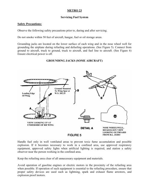
<strong>METRO</strong> <strong>23</strong><strong>Servicing</strong> <strong>Fuel</strong> <strong>System</strong><strong>Safety</strong> <strong>Precautions</strong>:Observe the following safety precautions prior to, during and after servicing.Do not smoke within 50 feet of aircraft, hangar, fuel or oil storage areas.Grounding jacks are located on the lower surface of each wing and in the nose wheel well forgrounding the airplane during refueling and defueling operations. (See Figure 5). Connect fromground to aircraft, truck to ground, truck to aircraft, and fuel line to aircraft. (See Figure 6)Ensure electrical power is off.GROUNDING JACKS (SOME AIRCRAFT)Handle fuel only in well ventilated areas to prevent toxic fume accumulation and possibleexplosion. If it becomes necessary to work in a confined area, use approved respiratoryequipment, approved safety lights when artificial lighting is required, and station a safetyobserver near the person working in the confined area.Keep the refueling area clear of all unnecessary equipment and materials.Avoid operation of gasoline engines or electric motors in the proximity of the refueling areawhen possible. If operation of such equipment is essential to the refueling procedure, ensure thatproper safety devices are used such as lightning, spark and exhaust flame arrestors, andexplosion proof motors.
Remove any spilled fuels and liquids from work stand and servicing area immediately and flushcontaminated area with water.Prevent fuel spillage from coming in contact with the skin. If spillage occurs, wash affected areaimmediately with soap and water.Do not use fuel as a cleaning agent for aircraft, components or tools.Allow sufficient time after refueling for clothing to air prior to smoking or working near powerequipment or open flame.Allow only qualified personnel to service the aircraft.The aircraft is designed for over-the-wing refueling with one fuel cap on the upper surface ofeach wing. There are no provisions for single-point refueling. Recommended pump pressure forover-the-wing refueling of this aircraft is 10 to 15 psi (20 psi max.). Using a small stepladder,bring the refueling hose over the wing leading edge and service tank to desired quantity.CAUTION: DO NOT ALLOW AFT PORTION OF FUEL NOZZLE OR HOSE TO RESTON DEICE BOOT. THE DEICE BOOTS ARE MADE OF SOFT, FLEXIBLE,SYNTHETIC RUBBER WHICH MAY BE DAMAGED IF HOSES ARE DRAGGEDOVER THE SURFACE OR IF LADDERS AND PLATFORMS ARE RESTED AGAINSTTHEM.
<strong>Fuel</strong>ing ProceduresUsable fuel capacity is 324 U.S. gallons per wing (648 gallons .total). The fuel quantity gaugecompensates for fuel density and reads tank quantity in pounds.NOTE: On a sloping ramp, the uphill tank may not accept a full fuel load if the downhill wingtank is filled first. When refueling on a sloping ramp, the uphill tank can be filled to maximumcapacity by refilling both tanks simultaneously, by refilling the uphill wing tank first, or byadding fuel to the wings alternately in approximately 125 gallon increments. When less thanmaximum capacity is required, this special fueling procedure is not necessary.When filling the wing tanks to maximum capacity under all conditions, expect the tanks toaccept the last 20 or 30 gallons at a slower rate because the last of the fuel requires extra time totravel to all of the fuel bays.After fuel tanks are serviced, remove fuel nozzle before disconnecting ground.Ensure tank caps are securely seated and locked (latch facing aft).<strong>Fuel</strong> Grades and TypesApproved <strong>Fuel</strong>sUse aviation fuel conforming to Garrett Installation Manual IM5117 (Jet A, Jet A-1, Jet B, JP-1,JP-4, JP-5, JP-8)Emergency/Alternate <strong>Fuel</strong>sGrade 100 LL aviation gasoline is permitted for emergency use, at a rate not to exceed 250 U.S.gallons (950 liters) per 100 hours of operation with total use limited to 7,000 U.S. gallons(26,500 liters) per engine overhaul period.Jet fuel and aviation gasoline may be mixed in any proportion. If 25% or more aviation gasolineis used, add one U.S. quart (one liter) of MIL-L-6082 specification grade 1065 to 1100 pistonengine oil per 100 U.S. gallons (380 liters) of aviation gasoline to provide fuel pump lubrication.CAUTION: THE USE OF AUTOMOTIVE GASOLINE, DIESEL FUELS, HEATINGFUELS OR ANY COMBINATION OF THESE PRODUCTS WITH JET FUELS AS ANALTERNATE OR EMERGENCY FUEL IS PROHIBITED.NOTE: The amount of aviation gasoline used must be recorded in the engine log book.Icing inhibitor MIL-1-27686E fuel additive or equivalent, is approved not to exceed 0.15% byvolume.For maximum demonstrated fuel imbalance for takeoff and landing see AFM.<strong>Fuel</strong> Drain ValvesDrain valves, one located in each wing tank lower skin between the nacelle and center section,and one on each nacelle outboard side under the wing at the main spar, are used for drainingcondensation or sediment. A small amount of fuel should be drained from each valve afterservicing and prior to the first flight of the day. To operate the valves, depress the center of the
valve, allow the desired amount of fuel to drain then release the valve. The valves are springloaded to the closed position.Defueling Aircraft1. Position aircraft at least 50 feet from any potential source of ignition.2. Static ground the aircraft using the grounding jacks (some aircraft) in the nose wheel well.3. Static ground the defueling equipment to ground and to the aircraft. The built-in groundingjacks (some aircraft) under the wings may be used for this purpose.4. Open the crossflow valve to drain both wing tanks. With the crossflow valve closed, only theright hand tank will drain. The crossflow valve is operated from the cockpit by turning on abattery switch (See Figure 40) and pressing the crossflow switch in the center of instrumentpanel. The crossflow switch/annunciator will illuminate displaying the words "X FLOWOPEN". Allow approximately three seconds for the valve to open fully, then turn off batterypower before continuing with step 5.5. Remove the access panel located at the center section just forward of the aft spar. Locate thefuel drain fitting with the dust cover (red nipple) attached. (See Figure 8)6. Remove the dust cover by depressing the end cap and pulling straight out.7. Remove the fuel filler caps.8. Install the fuel drain tube assembly (P/N 27-64043-001) or comparable drain hose assemblyby pressing straight on. <strong>Fuel</strong> will begin to flow when tube is connected.9. Defuel as required.10. When defueling operation is complete, install fuel filler caps and, using battery power, closethe crossflow valve. When the crossflow valve is fully closed, the crossflowswitch/annunciator light will extinguish. Turn off battery power.11. Disconnect the drain hose assembly and replace the dust cover by pressing straight on.12. Install the access panel.NOTE: Residual fuel may be drained at two sump drains located in each wing tank lower skinbetween nacelle and center section, and one on each nacelle outboard side, under the wing at themain spar.