Parallel Generators and Synchronization - AKSA Power Generation
Parallel Generators and Synchronization - AKSA Power Generation
Parallel Generators and Synchronization - AKSA Power Generation
- No tags were found...

You also want an ePaper? Increase the reach of your titles
YUMPU automatically turns print PDFs into web optimized ePapers that Google loves.
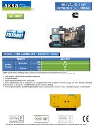
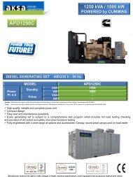
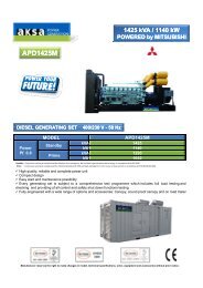
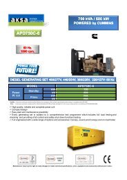
PARALLEL GENERATORS AND SYNCHRONIZATIONIII. Environment for installation <strong>and</strong> usage1.Ambient air temperature: ≮ -5℃ , ≯ +45℃ .(when the preheating arrangement is added, it can beused in environment at ≮ -30℃ temperature);2.Installation site:altitude ≯ 2000m;3.Relative humidity:≯ 90%,condensation on the surface;4.No conductive dust or fluid;5.No sufficient corrosive gas or vapor which destroy metal or fluid;;6.Occasion without explosion hazards;7.The place where there is no snow or rain;8.Installation condition: the vertical inclination of the cabinet with no more than 5 degrees.IV. Structure description <strong>and</strong> technical parameters of the switch cabinet for thegenerator sets1. Structure descriptiona)The framework adopts <strong>AKSA</strong> st<strong>and</strong>ard cabinet with surface treated with spraying plasticsb)TMY copper busbar is adopted <strong>and</strong> designed according to full load. The cable at the end of thegenerator sets is connected to the main switch through the upper <strong>and</strong> lower end of the cabinet <strong>and</strong>the output end of the main switch there retains a connecting copper busbar.2.Technical parametersa)Voltage of the generator sets:220VAC~480VAC;b)<strong>Power</strong> of a single set of the generator sets: 90~2000KW;c)Frequency:50HZ 或 60HZ;d)Wiring mode:Y-connecting methods / three-phase four-wire;e)Difference of phase synchronization: 5~10 0 ,generally set at 10 0 ;f)Deviation of load distribution:±5% adjustable;g)Reverse power action:0.5~20% adjustable;h)Positive power action:“NO” 20~100% adjustable“OFF” 0~80% adjustableFig 2: Switch cabinet for generator sets04
V. Operating principles of the auto parallel operation systemThe control system of the parallel operation cabinet adopts the PLC ( programmable logic controller) of the DSE7510 & DSE8610 Intelligent <strong>Parallel</strong> Generating Set made by Deep Sea Electronics plc (DSE)as the logic control device <strong>and</strong> the low-voltage switch cabinet, which is capable of automaticallycontrolling the startup <strong>and</strong> closed-down of the diesel engine through internal control program <strong>and</strong>corresponding external control signal according to the program-set control logic automatically. Itcombines the functions of load distribution, synchronous control, unit control into one completesystem. It has functions of unit control, monitoring <strong>and</strong> protection.This parallel operation system can automatically detect the three-phase output power (voltage <strong>and</strong>current) of the generators. It can output DC control signal to conduct real time adjustment to theAVR systems <strong>and</strong> the electronic fuel speed control systems of the generator sets so as to controlthe output power of each generator set <strong>and</strong> ensure the balanced distribution of active <strong>and</strong> reactivepower.1. Synchronize functionThis parallel operation system adopts the DSE7510&DSE8610 control module made by UK DSE asthe master control unit. It includes the functions of generator sets control, synchronization control<strong>and</strong> load distribution. It can internally <strong>and</strong> automatically conduct contrastive analysis according tothe parameters as set by the program through detecting the three-phase wire voltage, frequencysignal of the generator set <strong>and</strong> the three-phase wire voltage, frequency signal of another generatorset to be in parallel connection. At the same time, this parallel operation system can output a DCsignal to act on the engine speed-controlling system as well as alternator regulating voltage system<strong>and</strong> to adjust the rotating rate of the generator sets, making the phase <strong>and</strong> the frequency of thevoltage signal to achieve the consistent <strong>and</strong> synchronic requirement. Then the system sends out thesynchronized signal to act on the circuit breaker which allows switching. When the switching is onsuccessfully, the parallel operation is completed <strong>and</strong> then the load distribution of the generator setscan be controlled.This parallel operation system can automatically detect the three-phase output power (voltage<strong>and</strong> current) of the generators. It can output a DC speed regulation control signal to act on theelectronic speed regulation control system of the engines accordingly to control the frequency ofrotating speed of the generator sets. In this manner, the fuel consumption is under control so thatthe balanced power of the generator sets is controlled. Meanwhile, the internal synchronous trackeris adopted to detect the frequency, phase angle <strong>and</strong> voltage between the st<strong>and</strong>by generator sets<strong>and</strong> the generator sets to be in parallel connection, during which, by constantly contrasting theinternal set programs <strong>and</strong> the parallel connection parameters, via the calculation by internal CPU,the DC voltage-regulation <strong>and</strong> speed-regulation signals are output to act respectively on the AVR(automatic voltage regulation system) of the generator sets. The EFC(electronic fuel control system)of the engines adjusts the output voltage of the generator <strong>and</strong> the rotating speed of the engine soas to meet the synchronous requirements (1. the effective value <strong>and</strong> wave form of the generator’svoltage must be the same; 2. the voltage phase of the two sets of generators must be equal; 3. thevoltage frequency of the two sets of generators must be equal; 4. the phase sequences of the twosets of generators must be equal) <strong>and</strong> control the switching-on <strong>and</strong> parallel connection of GCB(generator circuit breaker).05
Fig 3: The rate power <strong>and</strong> the reactive power of the generator sets setup by SE75103. Function of peak regulation(option)When the load of two or more sets in parallel operation varies, the set number of the generator setscan be increased or decreased according to the total load. The generator sets can automatically startup or close down based on the load level, resulting in the most economical manner for the sets towork.When one of the sets goes into normal working operation, UK DSE7510 parallel operation controlsystem can scan the change in load level. If the load exceeds 80% (adjustable) of the power value ofthe set, UK DSE7510&DSE8610 parallel operation control system will send a signal to start up thenext generator set. When such set is started successfully, UK DSE7510&DSE8610 parallel operationcontrol system can detect the voltage level, the frequency variation <strong>and</strong> the phase offset of eachgenerator set. When the above values of the two generator sets have deviation that is larger than thesetup value in parallel operation, UK DSE7510&DSE8610 parallel operation control system can adjustthe operating parameters of the generator sets. When the deviation of above values is adjustedto the right range, the signal is sent to switch on in parallel operation <strong>and</strong> the sets will operate inparallel connection. At this moment, the built-in load distributor of UK DSE7510&DSE8610 will startto work, automatically detect the loading ability of each set <strong>and</strong> automatically distribute load to theset according to load level so as to balance the loading of the generator sets.When two generator sets work in parallel operation, UK DSE7510&DSE8610 parallel operationcontrol system can scan the change in load level. If the load is lower than 30% (adjustable) of the full07
PARALLEL GENERATORS AND SYNCHRONIZATIONpower value of the first set, the built-in load distributor of UK DSE7510 &DSE8610 parallel operationcontrol system will transfer all load to the first set <strong>and</strong> send out a disconnection signal automaticallywhen this process is complete. The parallel operation between the two sets is disconnected <strong>and</strong> thedisconnected sets without load will close down <strong>and</strong> go to a st<strong>and</strong>-by situation after cooling in giventime.Fig 5: Function of peak regulation of DSE75104. Brief introduction on DSE7510&DSE8610parallel operation control system made by UK DSE:DSE7510&DSE8610 is the automatic engine control module that can self boot <strong>and</strong> stop the engineto indicate the operation status <strong>and</strong> the failure situation. The indicating method is to displayon the LED of the front panel <strong>and</strong> on the flashing LED. The selected operational procedures, thetiming device <strong>and</strong> the alarm can be changed by the user. This kind of modules has the functionof the synchronization <strong>and</strong> load distribution, including the auto synchronous control by built-insynchronometer, the conformity of the voltage <strong>and</strong> frequency as well as the device from switchingonto no-power electrical drainage. The modules can directly offer various flexible output, allowingconnection with the most general speed regulator <strong>and</strong> Automatic Voltage Regulator (AVR).UK DSE7510&DSE8610 is a LCD control module for auto monitoring the utility power, featured byremote control, remote metering <strong>and</strong> remote communication <strong>and</strong> also the control module for autostart, synchronization <strong>and</strong> load distribution. It enables conducting the measurement of variouselectrical parameters <strong>and</strong> large-screen liquid crystal display with the functions of manual <strong>and</strong> autoparallel operation <strong>and</strong> auto load distribution among every generator set according to automaticallyset proportion.08
UK DSE7510&DSE8610 can monitor the utility power supply (effective AMF function). It can startthe generator sets when the utility power falls below the limit <strong>and</strong> will automatically switch overthe load when utility power fails. In case of the failure of the sets, it will shut down the generatorsets automatically <strong>and</strong> emergently, indicating the real time cause which leads to the failure of thegenerator sets by flashing common alarming LED light, displaying the specific failure status throughthe LED on the panel.Since microprocessor design is applied to the module of UK DSE7510&DSE8610, it can satisfy themost complicated technological requirements as set forth by the manufacturers. The module isdesigned for auto start, normal operation <strong>and</strong> auto stop for the generator sets, display of variousparameters, operating status <strong>and</strong> failure situation of the generator sets. When the sets shut downautomatically due to the failure, the LED can display corresponding failure items. The internalparameters within the system can be configured through P810 interface to connect with PC. Themodule is provided with the RS232/RS485 communication ports (alternative), which can realize theremote communication completely according to the user’s requirements <strong>and</strong> at the same time,can offer real-time diagnosis to the users. The module is featured by its compact size <strong>and</strong> elegantappearance.Working mode of the controllerThe front panel of the module has the mode for stop, auto <strong>and</strong> manual buttons <strong>and</strong> each mode isprovided with LED indicator.When the switch is at OFF position (stop or reset mode), the direct current is disconnected withthe module. The relay runs <strong>and</strong> the alarming output closes down.When the switch is at AUTO position (auto mode), the system can self start after receiving startsignal in case of utility power failure.When the switch is at MANUAL position (manual start mode), press the green start button, thefuel electromagnetic valve acts <strong>and</strong> the motor begins to start.LCD Liquid Crystal DisplayProgrammable LED indicatorButton for function selectionButton for switch-ongenerating powerButton for switch-on utilitypowerButton for silencing testingButton for stop or resetstart buttonManual buttonAuto buttonFig 5: Operating instructions for the panel of DSE7510 controller09
VI. DELIXI CDW1 Series Frame-based StationaryACB (air circuit breaker)The air circuit breaker (ACB) is also called framed-based circuitbreaker <strong>and</strong> is a kind of electrical appliance of the mechanicalswitch that can connect up, bear <strong>and</strong> disconnect the currentunder normal circuit condition. It can also connect up, bearfor sometime <strong>and</strong> disconnect the current under the definedabnormal circuit condition.CDW1 Series ACBFunction introduction on CDW1 Series ACB: this ACB is laid outin vertical form. The left <strong>and</strong> right lateral plates of the contacthead system <strong>and</strong> the momentary excess current release areinstalled on one piece of insulation board. The arc extinguishingsystem is installed upside, the operating mechanism can beinstalled at the front or at the right side with “OFF”, “No”indicators <strong>and</strong> the button for manual disconnection. The shuntrelease is installed at the left upper <strong>and</strong> the under voltagerelease connecting to the semi axle of release is installed at the back. The rapidly saturable currenttransformer or the current <strong>and</strong> voltage transformer is around the lower busbar. The under-voltageequipment for delay time <strong>and</strong> the thermal relay or the semiconductor release can be respectivelyinstalled at the bottom. 。CDW1-2000 Circuit Breaker is laid out in vertical form <strong>and</strong> the frameworkis comprised of underframe, lateral plates <strong>and</strong> cross beams. The contact head system for each phaseis installed on the underframe <strong>and</strong> the arc extinguish chamber is installed upside. The operatingmechanism is at the right front of the circuit breaker, connecting to the contact head system via themain axle. The electrical operating mechanism combines the square axle with the mechanism intoone, being installed at the bottom of the circuit breaker for the usage of accumulation of energy ordirect closure of the circuit breaker. The closure after accumulation of energy is assumed by energyreleasingelectric magnet. An anti-rebound mechanism is installed at the upper of the left lateralplate to prevent the circuit breaker from bounding when it is disconnected. Various over currentreleases are installed beneath the circuit breaker according to different requirements <strong>and</strong> the overvoltage<strong>and</strong> shunt releases <strong>and</strong> the electrical operating control system are installed at the left side,of which the over-voltage <strong>and</strong> shunt releases are connected with the magnifying mechanism via therelease so as to reduce the tripping force of the circuit breaker. 12 pairs of auxiliary contact heads isfor the user to connect the secondary loop; the indicating signs to display the working position ofthe circuit breaker “1” <strong>and</strong> “0” <strong>and</strong> the indicator of “accumulation of energy” are on the panel,together with the buttons “1” <strong>and</strong> “0” (both pressed) for switch-on <strong>and</strong> switch-off. CDW1-2000Series Circuit Breaker is attached with a manual operating h<strong>and</strong>le in the front.CDW1 Series Intelligent <strong>and</strong> ACB applies to the distribution network with AC 50 Hz, the ratedvoltage of 380V <strong>and</strong> 660 V <strong>and</strong> the rated current of 200A-6300A <strong>and</strong> it is mainly used to distributethe electricity energy <strong>and</strong> to protect the circuitry <strong>and</strong> equipments from the hazards of failures suchas the over load, undervoltage, short-circuit <strong>and</strong> the single-phase grounding; this circuit breaker isprovided with multi smart protective functions <strong>and</strong> can actualize selective protection, the action isaccurate, the unnecessary power off can be avoid <strong>and</strong> the power supply reliability can be increased.Universal Circuit Breaker is used to distribute the electricity energy <strong>and</strong> to protect the circuitry <strong>and</strong>the power supply equipment from the hazards of over load, undervoltage, short-circuit <strong>and</strong> so on,<strong>and</strong> can be used for non-frequent conversion of the circuits under normal conditions. In the network11