LS Series - TDK-Lambda
LS Series - TDK-Lambda
LS Series - TDK-Lambda

You also want an ePaper? Increase the reach of your titles
YUMPU automatically turns print PDFs into web optimized ePapers that Google loves.
<strong>LS</strong> 25<strong>LS</strong>25 SpecificationsITEMS/UNITSInputOutputFunctionEnvironmentMODEL<strong>LS</strong>25-3.3 <strong>LS</strong>25-5 <strong>LS</strong>25-12 <strong>LS</strong>25-15 <strong>LS</strong>25-24 <strong>LS</strong>25-36 <strong>LS</strong>25-48Voltage Range (*2) V AC88 to 264 or 125 to DC373 (Withstand AC300 Surge for 5 seconds)Frequency (*2) Hz 47-63Efficiency(230VAC)(typ) (*1) % 75 79 83 84 85Current(115/230VAC)(typ) (*1) A 0.7 / 0.4Inrush Current(typ) (*3) A 30A at 230VAC, Ta=25°C (Cold Start)Leakage Current (*10) mA < 1mA at 230VACNominal Voltage VDC 3.3 5 12 15 24 36 48Maximum Current A 6 5 2.1 1.7 1.1 0.75 0.57Maximum Power W 19.8 25 25.2 25.5 26.4 27 27.36Maximum Line Regulation (*5)(*6) mV 20 48 60 96 144 192Maximum Load Regulation (*5)(*7) mV 40 96 120 192 288 384Temperature CoefficientLess than 0.02%/°CMaximum Ripple & Noise (*1)(*4) mVp-p 80 120 150 200Hold-up Time(115/230VAC)(typ) (*1) ms 14 / 80Voltage Adjustable Range VDC 2.85 to 3.6 4.5 to 5.5 10.8 to 13.2 13.5 to 16.5 22 to 27.6 32 to 40 42 to 54Over Current Protection (*8) A > 110% rated output currentOver Voltage Protection (*9) VDC > 120% nominal output voltage<strong>Series</strong> OperationPossibleOperating Temperature (*11) °C - 25 to + 70 (Refer to Output Derating Curve)Storage Temperature °C - 40 to +85Operating Humidity %RH 20 to 90 (No dewdrop)Storage Humidity %RH 10 to 95 (No dewdrop)VibrationShock(In package)CoolingAt no operating, 10 - 55Hz (sweep for 1min)19.6m/s² Constant, X, Y, Z 1hour each.Less than 196.1m/s²Convection coolingIsolation Withstand Voltage Output - FG : 500VAC (100mA) for 1min.Input - Output : 3.0kVAC (20mA), Input - FG : 1.5kVAC (20mA)StandardsMechanicalIsolation ResistanceInput - FG, Input - Output and Output - FG: More than 100MΩ (500VDC) at 25°C and 70%RHSafety Standards Approved by UL60950-1, EN60950-1, IEC60950-1PFHC Built to meet IEC61000-3-2, -3EMIImmunityBuilt to meet EN55011/EN55022-B, FCC-BBuilt to meet EN61000-4-2 (Level 2,3), -3 (Level 3), -4 (Level 3),-5 (Level 3), -6 (Level 3), -8 (Level 4), -11Weight(typ) g 170Size (W×H×D) mm 79 x 51 x 28 (Refer to Outline Drawing)(*1) At Maximum Output Power, nominal input voltage, Ta = 25°C.(*2) For cases where conformance to various safety specs ( UL, CSA, EN ) are required, to be described as 100 - 240VAC, 50 / 60Hz on name plate.(*3) Not applicable for the in-rush current to Noise Filter for less than 0.2mS.(*4) Ripple & noise are measured at 20MHz by using a 300mm twisted pair of load wires terminated with a 0.1uF film capacitor and a 47uFelectrolytic capacitor.(*5) Measure line & load regulation at output terminal M3 tapped point.(*6) 88 - 264VAC, constant load.(*7) No load - Full load (Maximum power ), constant input voltage.(*8) Current limit with automatic recovery.Avoid to operate at overload or dead short for more than 30 seconds.(*9) Over voltage clamp by zener diode, hiccup mode.(*10) Measured by each measuring method of UL and EN (at 60Hz), Ta = 25°C.(*11) Refer to Output Derating Curve (PA580-01-02_) for details of output derating versus ambient temperature.(*12) All parameters NOT specifically mentioned are measured at 230VAC input, rated load and Ta = 25°C.・All specifications are subject to change without notice.
<strong>LS</strong> 25<strong>LS</strong>25 Outline DrawingVOLTAGEADJUSTMENTL N(AC) -V +V+ADJAC(L)AC(N)(FG)-V+V5-M344.8(6.5) (5.6)7.62(SEE NOTE B)25.4±0.351±1.0(10.6)(12.1)LED55±0.379±1.010.514 max.66.5±0.32.51428.5±1.0NAME PLATESEE NOTE ASEE NOTE BNOTESA. MODEL NAME, INPUT VOLTAGE RANGE, NOMINAL OUTPUT VOLTAGE, MAXIMUM OUTPUT CURRENT & COUNTRY OF MANUFACTUREARE SHOWN IN ACCORDANCE WITH THE SPECIFICATION.B. M3 TAPPED, EMBOSSED & COUNTERSUNK HOLES (4) FOR CUSTOMER CHASSIS MOUNTING.SCREWS MUST NOT PROTRUDE INTO POWER SUPPLY BY MORE THAN 4mm.C. UNLESS OTHERWISE SPECIFIED, DIMENSION TOLERANCE = ±0.3mm.<strong>LS</strong>25 Output Derating*COOLING : CONVECTION COOLINGTa (°C)-25 to +405070LOAD (%)10086.7(3.3V),100(OTHERS)60STANDARD MOUTINGTB1120OUTPUT DERATING CURVE100OthersLOAD(%)8070603.3V40200-25 0 2540507075 100Ta(°C)・All specifications are subject to change without notice.
<strong>LS</strong> 35<strong>LS</strong>35 SpecificationsITEMS/UNITSInputOutputFunctionEnvironmentMODEL<strong>LS</strong>35-3.3 <strong>LS</strong>35-5 <strong>LS</strong>35-12 <strong>LS</strong>35-15 <strong>LS</strong>35-24 <strong>LS</strong>35-36 <strong>LS</strong>35-48Voltage Range (*2) V AC88 to 264 or 125 to DC373 (Withstand AC300 Surge for 5 seconds)Frequency (*2) Hz 47-63Efficiency(230VAC)(typ) (*1) % 75 78 82 83 84Current(115/230VAC)(typ) (*1) A 0.8 / 0.55Inrush Current(typ) (*3) A 40A at 230VAC, Ta=25°C (Cold Start)Leakage Current (*10) mA < 1mA at 230VACNominal Voltage VDC 3.3 5 12 15 24 36 48Maximum Current A 7 3 2.4 1.5 1 0.8Maximum Power W 23.1 35 36 38.4Maximum Line Regulation (*5)(*6) mV 20 48 60 96 144 192Maximum Load Regulation (*5)(*7) mV 40 96 120 192 288 384Temperature CoefficientLess than 0.02%/°CMaximum Ripple & Noise (*1)(*4) mVp-p 80 120 150 200Hold-up Time(115/230VAC)(typ) (*1) ms 15 / 80Voltage Adjustable Range VDC 2.85 to 3.6 4.5 to 5.5 10.8 to 13.2 13.5 to 16.5 22 to 27.6 32 to 40 42 to 54Over Current Protection (*8) A > 110% rated output currentOver Voltage Protection (*9) VDC 3.8 to 4.45 5.75 to 6.75 13.8 to 16.2 17.25 to 20.25 29 to 32.4 41.4 to 48.6 55.2 to 64.8<strong>Series</strong> OperationPossibleOperating Temperature (*11) °C - 25 to + 70 (Refer to Output Derating Curve)Storage Temperature °C - 40 to +85Operating Humidity %RH 20 to 90 (No dewdrop)Storage Humidity %RH 10 to 95 (No dewdrop)VibrationShock(In package)CoolingAt no operating, 10 - 55Hz (sweep for 1min)19.6m/s² Constant, X, Y, Z 1hour each.Less than 196.1m/s²Convection coolingIsolation Withstand Voltage Output - FG : 500VAC (100mA) for 1min.Input - Output : 3.0kVAC (20mA), Input - FG : 1.5kVAC (20mA)StandardsMechanicalIsolation ResistanceSafety StandardsInput - FG, Input - Output and Output - FG: More than 100MΩ (500VDC) at 25°C and 70%RHApproved by UL60950-1, EN60950-1, IEC60950-1PFHC Built to meet IEC61000-3-2, -3EMIImmunityBuilt to meet EN55011/EN55022-B, FCC-BBuilt to meet EN61000-4-2 (Level 2,3), -3 (Level 3), -4 (Level 3),-5 (Level 4), -6 (Level 3), -8 (Level 4), -11Weight(typ) g 270Size (W×H×D) mm 99 x 82 x 36 (Refer to Outline Drawing)(*1) At Maximum Output Power, nominal input voltage, Ta = 25°C.(*2) For cases where conformance to various safety specs ( UL, CSA, EN ) are required, to be described as 100 - 240VAC, 50 / 60Hz on name plate.(*3) Not applicable for the in-rush current to Noise Filter for less than 0.2mS.(*4) Ripple & noise are measured at 20MHz by using a 300mm twisted pair of load wires terminated with a 0.1uF film capacitor and a 47uFelectrolytic capacitor.(*5) Measure line & load regulation at output terminal M3.5 tapped point.(*6) 88 - 264VAC, constant load.(*7) No load - Full load (Maximum power ), constant input voltage.(*8) Current limit with automatic recovery.Avoid to operate at overload or dead short for more than 30 seconds.(*9) OVP circuit will shutdown output, manual reset (Re-power on).(*10) Measured by each measuring method of UL and EN (at 60Hz), Ta = 25°C.(*11) Refer to Output Derating Curve (PA581-01-02_) for details of output derating versus ambient temperature.(*12) All parameters NOT specifically mentioned are measured at 230VAC input, rated load and Ta = 25°C.・All specifications are subject to change without notice.
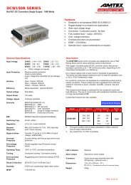
<strong>LS</strong> 75<strong>LS</strong>75 SpecificationsMODELITEMS/UNITS<strong>LS</strong>75-3.3 <strong>LS</strong>75-5 <strong>LS</strong>75-12 <strong>LS</strong>75-15 <strong>LS</strong>75-24 <strong>LS</strong>75-36 <strong>LS</strong>75-48Voltage Range (*2) V AC88-264 or DC125-373 (Withstand AC300 Surge for 5 seconds)Frequency Hz 47-63InputOutputFunctionEnvironmentIsolationStandardsMechanicalEfficiency (230VAC)(Typ)(*1) % 75 79 84 85 86 87Current (115/230VAC)(Typ) (*1) A 1.6 / 1.0Inrush Current (Typ) (*3) A 40A at 230VAC, Ta=25°C (Cold Start)Leakage Current (*10) mA < 1mA at 230VACNominal Voltage VDC 3.3 5 12 15 24 36 48Maximum Current A 15 12 6 5 3.2 2.1 1.6Maximum Power W 49.5 60 72 75 76.8 75.6 76.8Maximum Line Regulation (*5,6) mV 20 48 60 96 144 192Maximum Load Regulation (*5,7) mV 40 96 120 192 288 384Temperature CoefficientLess than 0.02%/°CMaximum Ripple & Noise (*1,4) mVp-p 80 120 150 200Hold-up Time (115/230VAC)(Typ) (*1) ms 14 / 60Voltage Adjustable Range VDC 3-3.6 4.75-5.5 10.8-13.2 13.5-16.5 22-27.2 32-40 42-54Over Current Protection (*8) A > 110% rated output powerOver Voltage Protection (*9) VDC 3.8 - 4.45 5.75-6.75 13.8-16.2 17.25-20.25 27.6-32.4 41.4-48.6 55.2-64.8<strong>Series</strong> OperationPossibleOperating Temperature (*11) °C - 25 to + 70 (Refer to Output Derating Curve)Storage Temperature °C - 40 to +85Operating Humidity %RH 20-90 (No dewdrop)Storage Humidity %RH 10-95 (No dewdrop)VibrationAt no operating, 10 - 55Hz (sweep for 1min), 19.6m/s² Constant, X, Y, Z 1hour each.Shock (In package)Less than 196.1m/s²CoolingConvection coolingWithstand VoltageInput - Output : 3.0kVAC (20mA), Input - FG : 1.5kVAC (20mA)Output - FG : 500VAC (100mA) for 1min.Isolation ResistanceInput-FG, Input-Output and Output-FG : More than 100MΩ (500VDC) at 25°C and 70%RHSafety StandardsApproved by UL60950-1, EN60950-1, IEC60950-1PFHC Built to meet IEC61000-3-2, -3EMIBuilt to meet EN55011/EN55022-B, FCC-BImmunityBuilt to meet EN61000-4-2 (Level 2,3), -3 (Level 3), -4 (Level 3),-5 (Level 4), -6 (Level 3), -8 (Level 4), -11Weight (Typ) g 410Size (W×H×D) mm 129×98×38 (Refer to Outline Drawing)(*1) At Maximum Output Power, nominal input voltage, Ta=25°C.(*2) For cases where conformance to various safety specs (UL, CSA, EN) are required, to be described as 100-240VAC, 50/60Hz on name plate.(*3) Not applicable for the in-rush current to Noise Filter for less than 0.2mS.(*4) Ripple & noise are measured at 20MHz by using a 300mm twisted pair of load wires terminated with a 0.1uF film capacitor and a 47uFelectrolytic capacitor.(*5) Measure line & load regulation at output terminal M3.5 tapped point.(*6) 88-264VAC, constant load.(*7) No load-Full load (Maximum power), constant input voltage.(*8) Current limit with automatic recovery.Avoid to operate at overload or dead short for more than 30 seconds.(*9) OVP circuit will shutdown output, manual reset (Re-power on).(*10) Measured by each measuring method of UL and EN (at 60Hz), Ta=25°C.(*11) Refer to Output Derating Curve (PA582-01-02_) for details of output derating versus ambient temperature.(*12) All parameters NOT specifically mentioned are measured at 230VAC input, rated load and Ta=25°C.10 ・All specifications are subject to change without notice.
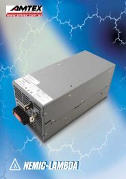
<strong>LS</strong> 75<strong>LS</strong>75 Outline Drawing6.48.0127±0.3?3.57LNAC(L)AC(N)(FG)67.58.3 9.5 (18.8)SEE NOTE B31-+-V+V33±0.385.5±0.398±1VOLTAGEADJUSTMENTLEDAVH5-M3.5Ø3.5(4.5)73.5±0.3129±1(6.5)(32)120±0.377±0.3Ø3.5 Ø3.51928.51018±0.328.538±1NAME PLATESEE NOTE BSEE NOTE ANOTESA. MODEL NAME, INPUT VOLTAGE RANGE, NOMINAL OUTPUT VOLTAGE, MAXIMUM OUTPUT CURRENT & COUNTRY OFMANUFACTURE ARE SHOWN IN ACCORDANCE WITH THE SPECIFICATION.B. M3 TAPPED, EMBOSSED & COUNTERSUNK HOLES (5) FOR CUSTOMER CHASSIS MOUNTING.SCREWS MUST NOT PROTRUDE INTO POWER SUPPLY BY MORE THAN 5mm.<strong>LS</strong>75 Output Derating*COOLING : CONVECTION COOLINGTa(°C)-25 to +5070LOAD(%)10070 (3.3 5V), 60 (OTHERS)STANDARD MOUTINGTB1120OUTPUT DERATING CURVE1003.3 5LOAD(%)80706040200-25 0 25 50 70 75 100Ta(°C)・All specifications are subject to change without notice.11
<strong>LS</strong> <strong>Series</strong>2. Terminal connecting method• Input must be off when making connection.• Connect FG terminal to ground terminal of the equipment.• The output load line and input line shall be separated and twisted to improve noise immunity.<strong>LS</strong>25, <strong>LS</strong>35, <strong>LS</strong>50, <strong>LS</strong>75<strong>LS</strong>100, <strong>LS</strong>150-LOAD+L N -V +V V ADJ HLOAD-+HL N -V -V +V +V VADJMaximum output current of each output terminal is 25A except for <strong>LS</strong>25 (15A).If more than 25A, use 2 terminals3. Explanation of Functions and Precautions Input Voltage RangeInput voltage range is single phase 88 - 264VAC (47 - 63Hz) or125 - 373VDC for <strong>LS</strong>25 to <strong>LS</strong>100.For <strong>LS</strong>150, selectable switch 115/230VAC will decide the inputvoltage range as mentioned in the table below.Input voltage which is out of specification, may damagethe unit. For cases where conformance to various safetyspecs(UL,CSA,EN) are required, input voltage range will be100 - 240VAC (50/60Hz).Note : <strong>LS</strong> series able to withstand Input Surge of 300VAC for 5 seconds.<strong>LS</strong>150 – Selectable voltage rangeSelected RangeApplicable InputVoltage Range in VACApplicable InputVoltage Range in VDC115 88 - 132 NA230 176 - 264 248 - 373 Output Voltage RangeV.ADJ trimmer is for output voltage adjustment within the rangeof specifications. Turning the trimmer clockwise will increasethe output voltage. Note over voltage protection ( OVP) functionmay trigger if the output voltage is increased excessively. Inrush CurrentPower Thermistor is built in to protect the circuit from InrushCurrent. Please select suitable input switch and fuse ratingin case of re-input the power at high temperature. Over Voltage Protection (OVP)The OVP function will shutdown the output except for <strong>LS</strong>25.The input need to be removed for a few minutes, and then reinputfor recovery of the output. OVP setting is fixed and cannotbe adjusted externally.Note : For <strong>LS</strong>25, OVP function will cause the output into ”hiccup”mode and damage the unit. Over Current Protection (OCP)OCP function operates when the output current exceeds OCPspecifications. The output will automatically recover when theoverload condition is removed. Do not operate overload ordead short conditions for more than 30 seconds, which couldresult in damage or insulation failure. Output Ripple & NoiseRipple & noise are measured at 20MHz by using a 300mmtwisted pair of load wires terminated with a 0.1uF film capacitor& 47uF electrolytic capacitor. When load lines are longer,ripple becomes larger. The output ripple cannot be measuredaccurately if the probe ground lead of oscilloscope is too long.At low temperature, large ripple & noise may also be observeddue to large ESR of the internal Electrolytic Capacitors especiallyat -25degC. Output voltage rise may not be smooth duringinitial turn on at low temperature.・All specifications are subject to change without notice.19
<strong>LS</strong> <strong>Series</strong> <strong>Series</strong> OperationFor series operation, either method ( A ) or ( B ) is possible.Method (A)OutputTerminalOutputTerminalMethod (B)PowerSupplyPowerSupplyLoad Parallel Operation(A) Operation to increase the Output Current is not possible.(B) Operation as a Backup Power Supply is possible as follows.1. Set the power supply output voltage higher by theamount of forward voltage drop (V F ) of the diode.2. Please adjust the output voltage of each power supplyto be the same.3. Please use within the specifications for output voltage(A)and output current.OutputTerminalPowerSupplyLoadOutputTerminalLoadOutputTerminalOutputTerminalLoad(B)OutputTerminalPowerSupplyNote : In case of Method ( A ), please connect diodes to preventthe reverse voltage.LoadOutputTerminal4. Isolation / Withstand Voltage Isolation TestIsolation resistance between output and FG (chassis) shall bemore than 100MΩ at 500VDC. For safety, voltage setting of DCisolation tester must be done before the test. Ensure that theunit is fully discharged after the test.(A) Output - FG (chassis) : 500VDC, 100MΩ or moreAC(L)AC(N)+V+V-V Withstand VoltageThis series is designed to withstand 3.0kVAC between inputand output, 1.5kVAC between input and FG (chassis) and500VAC between output and FG (chassis) each for 1 minute.When testing withstand voltage, set current limit of withstandvoltage test equipment at 20mA (Output-FG (chassis) :100mA). The applied voltage must be gradually increased fromzero to testing value and then gradually decreased for shutdown. When timer is used, the power supply may be damagedby high impulse voltage at timer switch on and off. Connectinput and output as follows.IsolationTesterFG-V20 ・All specifications are subject to change without notice.
<strong>LS</strong> <strong>Series</strong>(a) Input - FG (chassis) : solid line 1.5kVAC, 1min (20mA)(b) Input - Output : dotted line 3kVAC, 1min ( 20mA )AC(L)AC(N)+V+V-V-V(c) Output - FG (chassis) : 500VAC, 1min (100mA)+VAC(L)+VAC(N)-V-VFGWithstandVoltageTesterFGWithstandVoltageTester5. Mounting Directions Output Derating according to the Mounting DirectionsRecommended standard mounting is Method (A). Method (B),(C) and (D) are also possible. Refer to the Output Derating below.Please do not use installation Method (E), where the PCB will beon the topside and heat will be trapped inside the unit.In the following derating curve, the maximum output current isis denoted as 100%.<strong>LS</strong>25-5, -12, -15, -24, -36 & -48Load (%)12010080605040Output Derating Vs Ambient TemperatureMountingA & DMountingB & CSTANDARD MOUTING (A)(B)200-25 0 25405065 7075 100Ambient Temperature (ºC)(C) (D) (E) Not Possible<strong>LS</strong>35-3.3, -5, -12, -15, -24, -36 & -48Output Derating Vs Ambient TemperatureLoad (%)12010080605040MountingA, B & DMounting C20(1) Output Derating versus Ambient Temperature (ConvectionCooling)<strong>LS</strong>25-3.3Load (%)1201008060504020Output Derating Vs Ambient Temperature0-25 0 25405065 7075 100Ambient Temperature (ºC)MountingA & DMountingB & C0-25 0 25455065 7075 100Ambient Temperature (ºC)<strong>LS</strong>50 -3.3, -5, -12, -15, -24, -36 & -48Load (%)120100807060504020Output Derating Vs Ambient Temperature0-25 0 25405060 7075 100Ambient Temperature (ºC)MountingA, B & DMounting C・All specifications are subject to change without notice.21
<strong>LS</strong> <strong>Series</strong><strong>LS</strong>75-3.3, -5Output Derating Vs Ambient TemperatureLoad (%)120<strong>LS</strong>150 -12, -15, -24, -36 & -48Output Derating Vs Ambient TemperatureLoad (%)120100807060MountingA, B & DMounting C100807060Mounting AMountingB , C & D404020200-25 0 2545 60 7050 75 100Ambient Temperature (ºC)0-25 0 2540507075 100Ambient Temperature (ºC)<strong>LS</strong>75-12, -15, -24, -36 & -48Output Derating Vs Ambient TemperatureLoad (%)120100807060504020060 70-25 0 25 50 75 100Ambient Temperature (ºC)<strong>LS</strong>100 -3.3, -5Output Derating Vs Ambient TemperatureLoad (%)12010080605040200-25 0 2540 45507075 100Ambient Temperature (ºC)<strong>LS</strong>100 -12, -15, -24, -36 & -48Output Derating Vs Ambient TemperatureLoad (%)1201008060504020045 70-25 0 25 50 75 100Ambient Temperature (ºC)MountingA, B & DMounting CMountingA & BMountingC & DMountingA & BMountingC & D(2) Output Derating versus Input Voltage (ConvectionCooling)<strong>LS</strong>100 -3.3, -5, -12, -15, -24, -36 & -48Load (%)12010080604020Output Derating Vs Input Voltage088 115 230 264Vin (VAC)NOTE : <strong>LS</strong>25, <strong>LS</strong>35, <strong>LS</strong>50, <strong>LS</strong>75 & <strong>LS</strong>150 series do not requireInput Voltage Derating. Mounting Method(1) This is convection cooling type power supply. In considerationof the heat radiation and safety, please keep a distanceof more than 15mm between the power supply and the peripheralparts. When lining up multiple units, please makesure to place them 15mm or more apart from each other.(2) Maximum allowable penetration of mounting screwsinto thepower-supply is 5mm except <strong>LS</strong>25 (4mm).(3) Recommended torque for mounting screws of <strong>LS</strong>25 to<strong>LS</strong>150 (M3 screw) : 0.49 N·m (5.0 kgf·cm).Air Flow15mm or more 15mm or more<strong>LS</strong>150 -3.3, -5Load (%)120100Output Derating Vs Ambient TemperatureMounting ASheet MetalProvide punching, etc.to allow air to pass.80605040MountingB , C & D200-25 0302540507075 100Ambient Temperature (ºC)22 ・All specifications are subject to change without notice.
<strong>LS</strong> <strong>Series</strong>6. Wiring Method• The input and output load wires shall be separated andtwisted to improve noise immunity.• Both wires must be as thick and short as possible to makelower impedance.• Noise can be reduced by connecting a film capacitor with0.1uF capacitance across the load terminals.• For safety and EMI considerations, connect the FG terminalof <strong>LS</strong> series to mounting set ground terminal.• The recommended wire type :MODEL Recommended Wire Recommended torqueM3.0 Screws<strong>LS</strong>25AWG16-220.49 N·m (5.0 kgf·cm)M3.5 Screws<strong>LS</strong>35- <strong>LS</strong>150 AWG14-221.0 N·m (9.8 kgf·cm) - 1.4 N·m (13.7 kgf·cm)Recommended crimp-type terminalD (MAX) t (MAX)Mounting Pieces(MAX)6.0mm 0.8mm 2 piece6.8mm 0.8mm 2 pieceNote 1 : When using separate loads, it is recommended to use 2 pieces of 0.8mm thick crimp-type terminal.Note 2 : For recommended wire diameter, refer to wire maker recommended allowable current and voltage drop.For higher output current model like 3.3V & 5V, bigger diameter wire is recommended.7. External Fuse RatingRefer to the following fuse rating when selecting the externalinput fuse. Surge current flows when input turns on. Fuse ratingis specified by Inrush Current value at input turn on. Do notselect the fuse according to input current (rms) values underthe actual load condition.<strong>LS</strong>25 : F1.6A , 250V<strong>LS</strong>35, <strong>LS</strong>50 : T2A , 250V<strong>LS</strong>75 : T2.5A, 250V<strong>LS</strong>100 : F4A, 250V<strong>LS</strong>150 : F5A, 250V8. Before concluding that the unit is at fault, make the following checks.• Check if the rated input voltage is connected.• Check if the wiring of input and output is correct.• Check if the wire size is correct.• Check if the output voltage control (V.ADJ) is properly adjusted.• Check if the output current and output wattage does notexceed the specification.• Ensure that a large capacitor is not connected across theoutput terminals. Please use within maximum capacitanceshown below.Maximum external capacitanceMODEL 3.3V 5V 12V 15V 24V 36V 48V<strong>LS</strong>25 10,000uF 5,000uF 2,000uF 1,000uF 500uFL35 - <strong>LS</strong>50 10,000uF 5,000uF 2,000uF 500uF<strong>LS</strong>75 - <strong>LS</strong>150 10,000uF 5,000uF 1,000uFNOTE : It is normal to hear audible noise from power-supply under Dynamic Load operation or if the input voltage waveformis not sinusoidal.9. Warranty ConditionThis product is under warranty for 3 years (based on 8hours/day operation) from the date of shipment. During thewarranty period, <strong>TDK</strong>-<strong>Lambda</strong> will, at it’s option, either repairor replace products prove to be defective.Warranty applies but not limited to the following.• Average operating temperature (ambient temperature of thepower supply unit) is under 40°C.• Average load factor is 80% or less.• Installation method : Standard installation.Following cases are not covered by warranty.• Improper usage and mis-handling like dropping or applyingshock to the unit and defects from operation exceedingspecification of the product.• Defects resulting from natural disaster (fire, flood).• Unauthorized modification or repair.・All specifications are subject to change without notice.23