Era - Kim Lighting
Era - Kim Lighting
Era - Kim Lighting

Create successful ePaper yourself
Turn your PDF publications into a flip-book with our unique Google optimized e-Paper software.
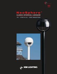
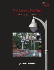
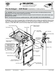
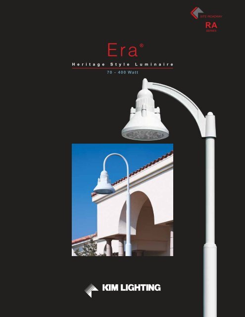
SITE /ROADWAYRASERIES<strong>Era</strong> ®H e r i t a g e S t y l e L u m i n a i r e70 - 400 Watt
<strong>Era</strong> ® <strong>Era</strong> ®Heritage Style Cutoff LuminairesTable of ContentsRelativity 2-3Style and Performance 4Integrated Design 6Design Features 8-9Optical System Features 10-11Mounting Configurations 12-13LuminaireOrdering Information 16-17Luminaire Specifications 18Option Specifications 19Options for Wall Mounting 20Integrated Pole OrderingInformation / Specifications 22-27Wind Map 28Proportion Guide 29Lamp and Electrical Guide 30-31ApplicationEngineering Services 31Inspired by the growth of the“Heritage Style” in design, the <strong>Era</strong>adds a new dimension to applyingthe superior performance of <strong>Kim</strong>optical systems.Optically identical to other <strong>Kim</strong>Site / Roadway systems, the <strong>Era</strong>offers an alternative to rectilinearshapes, without compromisingperformance.A wide range of integratedpole designs further expandsapplication flexibility.SITE / AREAPARKING STRUCTUREROADWAYARCHITECTURAL FLOODACCENTLANDSCAPEMAILING ADDRESS:P.O. BOX 60080CITY OF INDUSTRY, CA91716-0080BUSINESS ADDRESS:16555 EAST GALE AVENUECITY OF INDUSTRY, CA 91745U.S.A.PHONE 626 / 968 - 5666FAX 626 / 369-2695ENTIRE CONTENTS© COPYRIGHT 2010 KIM LIGHTING, INC.ALL RIGHTS RESERVEDREPRODUCTION IN WHOLE OR IN PARTWITHOUT PERMISSION IS STRICTLY PROHIBITED.U.S. PATENT D430,687www.kimlighting.comPrinted in U.S.A.5503310306Version 1.1 (11/10)
KIM LIGHTING 1
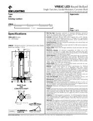
9999<strong>Kim</strong> <strong>Lighting</strong>’s Theory of RelativityThe Relationship of Outdoor <strong>Lighting</strong> to Site and ArchitectureRA25 Large <strong>Era</strong> ® RA17 Small <strong>Era</strong> ® VRB Vandal Resistant Bollard LTV Lightvault ®RA25As Distance to Architecture Decreases, Luminaire Height and Scale Also DecreasesLuminaire design and style remain constant to unify the lighting schemeRA17RA17SITE / ROADWAY ZONEParking lots and roadways require luminaires on 20' - 40' poles to efficiently lightthese large areas. Therefore, this lighting becomes dominant and sets the designand style for all other lighting as you progress towards the building.PEDESTRIAN ZONEAs you leave the parking lot and transition topedestrian areas, poles should decrease inheight to 10' - 16'. In addition, luminaires shoulddecrease in scale, and can have more decorativefeatures to be appreciated at the pedestrian level.2 KIM LIGHTING
AFL Architectural FloodlightWF Wall Forms ®WF Wall Forms ® WD Wall Director ®KIM LIGHTING’S THEORY OF RELATIVITYThe purpose of this guideline is to bring a cohesive look to outdoorlighting, maximizing lighting efficiency while preserving thearchitectural experience. Simply stated, the <strong>Kim</strong> Theory of Relativitysays “Poles belong in parking lots. And, once you leave the parkinglot, the outdoor lighting should become less and less conspicuousuntil it becomes an integral part of the architecture.” In addition, theluminaire style and geometry should remain consistent. If thisguideline is utilized, the outdoor lighting will enhance the site andarchitecture, bringing unity to the outdoor lighting scheme.WFVRBWFLTVAFLLANDSCAPE / PATH ZONENear the building, luminaires should beginto disappear, blending into the landscapeand hardscape elements.BUILDING / PERIMETER ZONENo pole mounted luminaires should ever be used near the building, as they willdominate the architecture. The only exception would be the use of decorativeluminaires to delineate entrances to the structure. Building mounted, architecturallycompatible fixtures should be almost invisible.KIM LIGHTING 3
Style and PerformanceAesthetics without CompromiseApproachUnlike most <strong>Kim</strong> product innovations that have a singular designtheme, <strong>Era</strong> ® is unique. We wanted to develop a luminaire that wasequally at home in either a traditional or contemporary setting; aninternational style fixture capable of establishing a visual unity withmany architectural themes. To accomplish this, <strong>Era</strong> combines basicdesign elements of both traditional and contemporary luminaires,skillfully orchestrated into a cohesive product design with appealingproportions and elegant detailing.<strong>Era</strong> incorporates <strong>Kim</strong>’s most up-to-date optical systems, with fourhorizontal lamp reflectors and two vertical lamp reflectors. Sacrificingperformance to include style of this caliber is no longer required.1W Wall Mount arm notincluded and must beordered separately.See p. 20 for ordering.PerformanceIn every respect, <strong>Era</strong> is optically equal to any <strong>Kim</strong> Site / Roadwayluminaire. The reflectors used are the same as those available in theextensive <strong>Kim</strong> Site / Roadway product line. Incorporating fullyrotatable orientation and sealed optical chambers, <strong>Era</strong> offers analternative to rectilinear designs without sacrificing illuminationperformance.Robust ComponentsCastings and extrusions are used to produce precise and durabledetailing. Tight fitment and rigid construction insure clean componentattachment and tight sealing against intrusion of contaminants.4 KIM LIGHTING
KIM LIGHTING 5
Integrated DesignComplementary DetailingIntegration<strong>Era</strong> design approaches alldetailing as integral pieces ofthe whole. From the use ofits clean bell shape for theOptical Housing and exposedcooling surfaces on the BallastHousing, to the detailing of themounting arms and poles, <strong>Era</strong>is complete.Combining proven mechanicalfeatures with a highly styledpackage without sacrificingeither performance or aestheticdesign is a difficult task. <strong>Era</strong>answers this challenge, withflexibility to satisfy a wide rangeof architectural tastes.The luminaire, mounting arms, andpoles were developed with shareddetailing and complementarymating components. Thisapproach produces a completedesign that is robust in style andmechanical integrity.HA01S/HA01LPost Top Crook ArmHA02S/HA02LSide Mount Crook ArmHA03S/HA03LPost Top Swept Cast Arm1W Wall MountRA17 shown with HA02SWwall mount option. Wall mountarm is not included and mustbe ordered separately. Seepage 20 for ordering.6 KIM LIGHTING
KIM LIGHTING 7
Design FeaturesPrecision and DurabilityDie-Cast Aluminum ComponentsThe <strong>Era</strong> housing and door frame are die-cast, low copper (
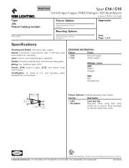
Sealed Optical SystemThe optical compartment is completely sealed from outside andinside including wire entries to the socket. The tempered clearglass lens is sealed by molded silicone gaskets at the opticalcompartment. By eliminating the intrusion of moisture, dust, andinsects, the efficiency of the optical system is maintained. Thisassures maximum light output between standard maintenanceintervals.Optional Glow RingThe optional glow ring receives illumination from a sealedwindow in the optical system. This produces just the rightamount of accent light, while maintaining the integrity of thesealed optical chamber.HousingSelf-RetainedScrewSealed Die-castReflector ModuleTemperedClear Glass LensSiliconeGasketCast AluminumLens FrameVentilated Ballast CompartmentThe ballast housing of the <strong>Era</strong> luminaire draws ventilation air fromaround the sealed optical assembly to maintain the lowestpossible operating temperature.BallastHousingCooling AirSealed OpticalChamberKIM LIGHTING 9
Optical System FeaturesHorizontal or Vertical LampSee the <strong>Kim</strong> Site / Roadway Optical Systems Catalog for complete details and explanation of optical system features.Horizontal LampAvailable in Type II, Type III, Type IV, and Type V Squaredistributions. This flat lens system provides full cutoff control andvery good uniformity.Sealed optics and performance reflector technology allow thishorizontal lamp optical system to maximize lamp output. An optionalhouseside shield is available for Types II, III, and IV distributions.HorizontalLampFlat LensType II Type III Type IV Type VOptional Convex LensAn optional convex lens offers increased lens presence, a subtleimprovement in uniformity and increased effectiveness of housesideshielding.OptionalConvex LensVertical LampAvailable in Asymmetric and Symmetric distributions in widerange. Provides vertical lamp performance in a compact luminaireprofile with excellent uniformity.The reflector utilizes <strong>Kim</strong>’s split beam reflector technology,optimizing lamp output and life (see below). An optional housesideshield is available for the Asymmetric distribution.VerticalLampConvex LensSplit Beam ReflectorGeometryWide-beam vertical lampreflectors will redirect light backinto the lamp unless properlydesigned. <strong>Kim</strong> reflectors areprecision engineered to avoidthis by using split-beamreflector geometry.AsymmetricF3Reflected light does not passthrough the lamp envelope,which otherwise will reducelamp life and efficiency.SymmetricF5Split beams of reflected lightpass freely and efficientlyout of the luminaire.10 KIM LIGHTING
Adaptability and ControlRotatable OpticsAll asymmetric reflectors are field rotatable in 90° increments. Thisallows design flexibility in producing very high illumination levelsfor special applications or for maintaining a consistent fixtureorientation throughout the site. To facilitate field rotation, eachreflector is labeled to show the orientation of the light pattern.Cutoff ControlLuminaires with good cutoff characteristics produce less lightpollution and distribute a greater portion of their output intousable lighting zones. This is not only more efficient, itproduces a more conscientious and environmentally friendlylighting design.HorizontalLampType IIType IIIType IVVerticalLampAsymmetricF3Rotatable reflectors offer a degree of refinement in fixture orientationwhen the architecture and site demand perfection.When the twin-mountedluminaires are used for sitelighting using Types II, III or IVdistributions, the combinedeffect from the twin mount is arectangular light pattern.To change the orientation of therectangular pattern, younormally change the orientationof the twin mount. Analternative to this is shown atright, where the fixtureorientation remains constantand the internal reflectors rotateto change the orientation of therectangular light pattern. Thiscan maintain identical fixtureorientations throughout the site.For applications demandinghigh light levels, such as tenniscourts and automobiledealerships, reflectors can berotated in parallel to double thelight levels. Houseside shieldscan be added to the fixtures forreducing spill light intounwanted areas behind theluminaires. See page 19.KIM LIGHTING 11
Mounting ConfigurationsCrook ArmsHA01S/HA01LPost Top Crook ArmExtruded Crook ArmHA02S/HA02LSide Mount Crook ArmExtruded Crook ArmThe luminaire head is bolted tothe crook arm with two largestainless steel bolts.The luminaire head is bolted tothe crook arm with two largestainless steel bolts.The crook arm slip fits and isbolted into the pole top.The crook arm is securely boltedto the pole under decorativecovers.The pole step transition isreinforced and fully welded.The pole step transition isreinforced and fully welded.Available ConfigurationsAvailable Configurations1A1W 1A 2BThe pole base is doublewelded and includes a fullcast cover.3Y4CThe pole base is doublewelded and includes a fullcast cover.12 KIM LIGHTING
Swept ArmHA03S/HA03LPost Top Swept Cast ArmHeavy Cast ArmThe luminaire head is bolted tothe crook arm with two largestainless steel studs.The cast arm is attached to acast pole-top fitter with largestainless steel bolts.The pole step transition isreinforced and fully welded.Available Configurations1A3Y2B4CThe pole base is doublewelded and includes a fullcast cover.KIM LIGHTING 13
14 KIM LIGHTING
KIM LIGHTING 15
Luminaire Ordering Information<strong>Era</strong> ® SeriesRA1770 to 175 WattRA25150 to 400 WattOrdering Example:For Standard Fixture and Pole1 Mounting:2 Fixture:Cat. No. designates RA fixtureand light distribution.See the <strong>Kim</strong> Site/RoadwayOptical Systems Catalog fordetailed information on reflectordesign and application.HorizontalLamp3 Electrical Module:VerticalLampPMH = Pulse Start Metal HalideMH = Metal HalideHPS = High Pressure SodiumLamp Lamp LineWatts Type Volts400 HPS 2774 Finish:Super TGIC powder coatpaint over titanated zirconiumconversion coating.5 Optional Glow Ring:Pole & ArmMounting Fixture Electrical Module Finish Options Pole Optional Arm Finish1A /RA173/150PMH277/ LG/A-33/ HSAS14-534188A / HA01S-TM1/ LG1 2 3 4 5-10 11 12-14Plan View:Horizontal LampSee pages 22 - 27Omit for 1W Wall Mount.Cat. No.: 1A 2B 3Y 4C 1WEPA 17": 0.8 1.6 2.4 2.8 n/aEPA 25": 1.5 3.0 4.5 5.2 n/aWallMountNOTE: 1A, 2B, 3Y, and 4C mounting arms are part of the Pole Assembly (pages 22 - 27) or Slipfitter Mount(page 19). 1W Wall Mount arm not included and must be ordered separately. See page 20 for styles andordering information.Flat LensFull CutoffLight Distribution: Type I Type II Type III Type IV Type VForward Throw SquareCat. No.: 17" RA171 RA172 RA173 RA174 RA17525" RA251 RA252 RA253 RA254 RA255Vertical LampConvex LensCutoffLight Distribution: Asymmetric SymmetricSquareCat. No.: 17" RA17F3 RA17F525" RA25F3 RA25F5RA17 17" HousingRA25 25" HousingPulse Start Metal Halide High Pressure Sodium Pulse Start Metal Halide High Pressure Sodium100PMH120100PMH208100PMH240100PMH277100PMH347100PMH480Cat. No.: GR175PMH120 1175PMH208 1175PMH240 1175PMH277 1175PMH347 1175PMH480 170HPS12070HPS20870HPS24070HPS27770HPS34770HPS480100HPS120100HPS208100HPS240100HPS277100HPS347100HPS480150HPS120150HPS208150HPS240150HPS277150HPS347150HPS480150PMH120150PMH208150PMH240150PMH277150PMH347150PMH4801175PMH lamp not for use in horizontal lamp reflectors.175PMH120 1175PMH208 1175PMH240 1175PMH277 1175PMH347 1175PMH480 1250PMH120250PMH208250PMH240250PMH277250PMH347250PMH480400PMH120400PMH208400PMH240400PMH277400PMH347400PMH480Diffuse tempered glass securely held between the Ballast Housingand the Reflector Housing with stainless steel fasteners and siliconegaskets.150HPS120150HPS208150HPS240150HPS277150HPS347150HPS480250HPS120250HPS208250HPS240250HPS277250HPS347250HPS480400HPS120400HPS208400HPS240400HPS277400HPS347400HPS480NOTE: Due to the Energy Independence and Security Act (EISA) of 2007, <strong>Kim</strong> <strong>Lighting</strong> can no longer supply probestart metal halide ballasts with its luminaires, effective January 1, 2009. Contact <strong>Kim</strong> <strong>Lighting</strong> for availability ofreplacement ballasts for warranty service claims.(Visit www.aboutlightingcontrols.org or the Library of Congress website for more details).Color: Black Dark Bronze Light Gray Stealth Gray Platinum Silver White Custom ColorsCat. No.: BL DB LG SG PS WH CCConsultrepresentativefor custom colors.GlowRing6 Optional Photocell:One per fixture required.Line Volts: 120V 208V 240V 277V 480V 347VCat. No.: A-30 A-31 A-32 A-33 A-34 A-357 Optional Convex GlassLens:For Horizontal Lamp OpticalSystems.Cat. No.: CGLTempered convex glass lens replaces standard flat lens.For horizontal lamp Type II, Type III, Type IV, and Type Vdistributions. Changes light distribution from Full Cutoff to Cutoff.NOTE: Convex lens is standard on all Vertical Lamp Optical Systems.ConvexLens16 KIM LIGHTING
8 Optional PolycarbonateLens:Cat. No.: LSPolycarbonate Lens replaces standard tempered glass lens.250 watt maximum. May be used with 400HPS in outdoor locationswhere ambient air temperature during fixture operation will notexceed 85°F. Changes light distribution on horizontal lamp modelsfrom Full Cutoff to Cutoff. See “CAUTION” on page 19.Polycarbonate Lens9 Optional HousesideShield:10 Optional Fusing:11 Poles:Cat. No.: HSCat. No.: HSCRecommended for use with clear lamps only. Effectiveness isreduced for coated lamps. Not for use with Type V (horizontallamp) or symmetric (vertical lamp) light distributions.For use with all fixtures with convex glass lens. Not for use withType V or symmetric light distributions.Line Volts: 120V 208V 240V 277V 347V 480VCat. No.: SF DF DF SF SF DFSee pages 22 - 27 for complete ordering and specification information.HS forflat lensSingle FuseHSC forconvex lens orpolycarbonatelens12 Optional SlipfitterArm Mounting forPoles by others:See page 19 for completedetails and configurationsavailable.NOTE: Arm assemblies for<strong>Kim</strong> poles are shown in Polessection.RA17 Post Top Crook Arm Side Mount Crook Arm Post Top Swept Cast ArmConfiguration: 1SA HA01S-TM 1SA HA02S-TM1 1SA HA03S-TM1and Cat. No.: 2SB HA02S-TM2 2SB HA03S-TM2Requires 2" (2C" O.D.) 3SY HA02S-TM3 3SY HA03S-TM3Steel Tenon 4SC HA02S-TM4 4SC HA03S-TM4RA25 Post Top Crook Arm Side Mount Crook Arm Post Top Swept Cast ArmConfiguration: 1A HA01L-TM 1A HA02L-TM1 1A HA03L-TM1and Cat. No.: 2B HA02L-TM2 2B HA03L-TM2Requires 2K" (2E" O.D.) 3Y HA02L-TM3 3Y HA03L-TM3Steel Tenon 4C HA02L-TM4 4C HA03L-TM413 Optional Support Arm:Drawings not to scalePost Top Side Pole Post Top Side Pole Side Pole S-Shaped Side PoleCrook Arm Crook Arm Swept Cast Arm Swept Cast Arm Up Cast Arm Neo-Classic ArmRA17 RA25 RA17 RA25 RA17 RA25 RA17 RA25 RA17 RA25 RA17 RA25Cat. No.: HA01S HA01L HA02S HA02L HA03S HA03L HA11S HA11L HA12S HA12L HA14S HA14LEPA for Fixture and ArmMounting: RA17 RA25 RA17 RA25 RA17 RA25 RA17 RA25 RA17 RA25 RA17 RA251SA/1A 1.1 1.8 1.3 1.9 1.3 1.9 1.5 2.3 1.4 2.0 1.7 2.62SB/2B – – 2.6 3.8 2.6 3.8 3.0 4.8 2.8 4.0 3.4 5.23SY/3Y – – 3.5 5.1 3.4 5.0 3.8 5.8 3.6 5.2 4.2 6.44SC/4C – – 3.9 5.9 3.7 5.5 4.1 6.3 3.9 5.7 4.5 6.9Side Pole Ribbon Side Pole Ribbon Side Pole Ribbon Side Pole Ribbon Side Pole RibbonArm w/ Top Scroll Arm w/ Top Gusset Arm w/ Top Brace Arm w/ Top Brace Arm w/ Top Brace& Bottom Scroll & Bottom GussetRA17 RA25 RA17 RA25 RA17 RA25 RA17 RA25 RA17 RA25Cat. No.: HA31S HA31L HA33S HA33L HA35S HA35L HA37SHA37L HA38S HA38LEPA for Fixture and ArmMounting: RA17 RA25 RA17 RA25 RA17 RA25 RA17 RA25 RA17 RA251SA/1A 1.7 2.6 1.8 2.8 1.6 2.6 1.8 2.8 2.0 3.02SB/2B 3.3 5.2 3.6 5.6 3.4 5.2 3.6 5.6 4.0 6.03SY/3Y 4.0 6.2 4.4 6.8 4.3 6.6 4.5 6.9 4.9 7.44SC/4C 4.3 6.7 4.7 7.3 4.6 7.1 4.8 7.4 5.2 7.9NOTE: Refer to <strong>Kim</strong> <strong>Lighting</strong>’s Arms & Poles Selection Guide for dimensions and details.See p. 20 for wall mounting feature.14 Optional Arm Finial:Cat. No.: HAF2Traditional style finial avaialble to close off mounting hub oppositethe fixture. Available only on selected <strong>Era</strong> arms. Refer to <strong>Kim</strong> Armsand Poles Selection Guide for a complete selection of heritagestyle finials.Arm FinialsKIM LIGHTING 17
Luminaire Specifications<strong>Era</strong> ® ModelsDimensionsRA176"16K"RA17with optionalGlow Ringand Convex LensRA25RA25with optionalGlow Ringand Convex Lens17K"1"1L"22"23K"17"8"25"Housing: The Ballast Housing is a one piece die-cast, low copper(
Option SpecificationsSee pages 16-17 for complete ordering informationWall Mounting: Cast aluminum wall mounting plate pre-attaches towall with bolts (by others). A cast cover with crook attachmentshangs on mounting plate during field wiring and fastening. Splicecover supplied. See photo on page 4. 1W Wall Mount arm notincluded. See page 20 for ordering.RA17RA2534K"50D"C L 25"7K"39"C L7K"15K"12"C L17I"C L17I"Glow Ring: Diffuse tempered glass securely held between theBallast Housing and Reflector Housing with stainless steel fastenersand silicone gaskets. Extruded aluminum spacers extend BallastHousing to Reflector Housing connections. See photo on page 9.Photocell ControlGlow RingPhotocell Control: Factory installed fully gasketed sensor.Convex Glass Lens: The F" thick clear convex tempered glasslens replaces the standard flat glass lens in horizontal lamp fixtures.Provides increased lens presence and provides a subtle improvementin uniformity where pole spacing is extreme.NOTE: Convex Lens is standard on all Vertical Lamp Optical Systems.Polycarbonate Lens: One piece vacuum formed, clear, UV stabilizedconvex polycarbonate, fully gasketed, replacing the standardtempered glass lens. 250 watt maximum. May be used with 400 wattHPS in locations where ambient air temperature during fixtureoperation will not exceed 85°F.CAUTION: Use only when vandalism is anticipated to be high. Usefullife is limited by UV discoloration from sunlight and metal halide lamps.Houseside Shield: (Types II, III, IV, and Asymmetric distributionsonly). The cutoff horizontal reflectors are available with stampedaluminum louvers that pass streetside light and block housesidelight, and a blackened panel added to the reflector to reducehouseside reflections. The vertical reflectors and horizontal reflectorswith the optional convex glass lens are available with a formedaluminum shield that passes streetside light and blocks housesidelight, and a blackened panel added to the reflector to reducehouseside reflections.Fusing: High temperature fuse holders factory installed. Fuse is included.Slipfitter Mounts for Poles by others:For steel tenons onlyCast aluminum tenonadapter, bolted toextruded and formedarm. Secured by fourC" stainless steel setpoint allen screws.Pole Top TenonRA17 - 7"RA25 - 7N"Cast aluminum tenonadapter, bolted toextruded and formedarm. Secured by thrubolt and four C"stainless steel setpoint allen screws.Pole Top TenonHouseside Shield for flat lensCH*RA17 - 26"RA25 - 37"CH*RA17 - 34"RA25 - 46" RA17 - 17L"RA25 - 23N"Cast aluminum tenonadapter and arm.Secured by four C"stainless steel setpoint allen screws.Pole Top TenonPole supplied by others Pole supplied by others Pole supplied by othersConvex Glass Lens orPolycarbonate LensHouseside Shield for convex lensor polycarbonate lensHA01S fits 2" steel pipe-size tenonHA01L fits 2K" steel pipe-size tenonHA02S fits 2" steel pipe-size tenonHA02L fits 2K" steel pipe-size tenonHA03S fits 2" steel pipe-size tenonHA03L fits 2K" steel pipe-size tenon*NOTE: CH and SH Detailing and Arm Spacing Dimensions match corresponding pole arm designs, see pages 22 - 26.SH*RA17 - 22"RA25 - 28"KIM LIGHTING 19
Wall Mounting OptionsHA02LW Large Side Crook Arm Wall MountHA11LW Swept Cast Arm Wall MountHA12LW S-Shaped Up Cast Arm Wall Mount7K"(191 mm)8D"(219 mm)8D"(219 mm)17E"(454 mm)27"(686 mm)27"(686 mm)HA02SW Small Side Crook Arm Wall MountHA11SW Swept Cast Arm Wall MountHA12SW S-Shaped Up Cast Arm Wall Mount7K"(191 mm)7"(178 mm)7"(178 mm)15K"(394 mm)22"(559 mm)22"(559 mm)HA14LW Neo-Classic Arm Wall Mount8D"(219 mm)HA31LW Ribbon Arm with Top Scroll Wall Mount8D"(219 mm)HA33LW Ribbon Arm with top GussetWall Mount8D"(219 mm)27"(686 mm)27"(686 mm)27"(686 mm)HA14SW Neo-Classic Arm Wall Mount7"(178 mm)HA31SW Ribbon Arm with Top Scroll Wall Mount7"(178 mm)HA33SW Ribbon Arm with top GussetWall Mount7"(178 mm)22"(559 mm)22"(559 mm)22"(559 mm)NOTE: Wall mount arm is not included and must be ordered separately.20 KIM LIGHTING
KIM LIGHTING 21
Pole Ordering Information and SpecificationsHSAS Stepped Aluminum Pole & Single Post Top Crook ArmOrdering Example:For Standard HA01S / HA01L PolePole Cat. No. and Mounting Finish OptionHSAS10-534188A / DB / DR1-2 3 41 Pole Catalog Numbers:For RA17 Luminaires onlyALLOWABLE POLE EPA*CHCDX2XX1CSY2Pole StepY1Hand HolePoleCatalogNumber X X1 X2 Y1 Y2Wall ThicknessBolt Circle Dia.HSAS10-534188 10' 6.5' 3.5' 5" 3.4" .188" 8K" 34" 20" 1D" 3.2" L"x15"+3" 12" 3" 25.7 23.5 19.1 15.8 13.2 11.2 9.5HSAS12-534188 12' 8' 4' 5" 3.4" .188" 8K" 34" 20" 1D" 3.2" L"x15"+3" 12" 3" 20.6 18.8 15.2 12.5 10.3 8.7 7.3HSAS14-534188 14' 9.3' 4.7' 5" 3.4" .188" 8K" 34" 20" 1D" 3.2" L"x15"+3" 12" 3" 16.9 15.3 12.3 10.0 8.2 6.8 5.7HSAS16-534188 16' 10.5' 5.5' 5" 3.4" .188" 8K" 34" 20" 1D" 3.2" L"x30"+4" 12" 3" 14.1 12.7 10.0 8.1 6.5 5.3 4.4HSAS20-534188 19.5' 13' 6.4' 5" 3.4" .188" 8K" 34" 20" 1D" 3.2" L"x30"+4" 12" 3" 9.6 8.6 6.6 5.1 4.0 3.1 2.4For RA25 Luminaires onlyPoleCatalogNumber X X1 X2 Y1 Y2Wall ThicknessBolt Circle Dia.NOTE: All allowable pole and fixture EPAs (Effective Projected Area, which is Fixture Area x Drag Factor) arederived from the AASHTO standard (American Association of State Highway and Transportation Officials).Responsibility lies with the specifier for correct pole selection based on local codes and standards for the joblocation (See page 28).1Thickness at Y1 section, Y2 section is .188".Arm assemblies are included.CH / Crook HeightCS/ Crook SpacingCD / Crook Dia.Anchor BoltProjectionCH / Crook HeightCS/ Crook SpacingCD / Crook Dia.Anchor BoltProjectionAnchor BoltsBase Cover Dia.Conduit Opening Dia.90100110120130140150ALLOWABLE POLE EPA*HSAS20-64188 19.5' 13' 6.4' 6" 4" .188" 10K" 46" 30" 2F" 3.2" L"x30"+4" 14" 5" 15.2 13.9 11.0 8.7 7.1 5.9 4.9HSAS25-64188 25' 16.7' 8.3' 6" 4" .188" 10K" 46" 30" 2F" 3.2" L"x30"+4" 14" 5" 9.5 8.6 6.5 4.9 3.7 2.9 2.31HSAS30-64250 30' 20' 10' 6" 4" .250" 10K" 46" 30" 2F" 3.2" L"x30"+4" 14" 5" 9.3 8.4 6.2 4.5 3.4 2.6 2.0Anchor BoltsBase Cover Dia.Conduit Opening Dia.90100110120130140150Base Cover2 MountingArrangements:Plan View:Mounting Cat. No.: AEPA: RA17 0.8RA25 1.5*NOTE: ALLOWABLE POLE EPA for jobsite wind conditions must be equal to or greater than fixture mount EPA.22 KIM LIGHTING
HSASStepped Aluminum Pole& Single Post Top Crook Arm3 Pole Finish:Super TGIC powder coatpaint over Titanated Zirconiumconversion coating.4 Optional DuplexReceptacle:Color: Black Dark Bronze Light Gray Platinum Silver White Custom ColorsCat. No.: BL DB LG PS WH CCConsult representativefor custom colors.Mounted opposite the handhole in a cast aluminum box, internally welded and sealed with a gasketedself-closing cover and locking bracket.DR Duplex Receptacle rated 15A., 125V.DR-GFI Duplex Receptacle with Ground Fault Circuit Interrupter rated 15A., 125V.SpecificationsPlan ViewBase CoverLongitudinalreference line.Orient parallelto curb or walkway.Leveling Nutand Washer45°Bolt CircleDiameterAnchor BoltProjectionConduit OpeningPresswoodTemplatePole Construction: Seamless round extruded aluminumtube of alloy 6063-T6, welded to top and bottom ofaluminum base casting of alloy 356. Base has a twopiece cast aluminum full cover of 319 alloy and issecured by stainless steel screws.Handhole: 18" up from base, with a gasketed cover andground lug.Mounting Accessories: Four galvanized anchor boltsprovided complete with eight nuts, eight flat washers,and a presswood template.Strength: Poles shall withstand steady winds as listed inchart (see opposite page) when luminaires are mountedper fixture installation instructions.CAUTION: Do not install poles without luminaires orstrength guarantee is voided. Any unauthorizedaccessories secured to pole shall void strengthguarantee.Finish: Super TGIC thermoset polyester powder coatpaint applied over a titanated zirconium conversioncoating. Standard colors are Black (BL), Dark Bronze(DB), Light Gray (LG), Platinum Silver (PS), andWhite (WH). Custom colors are available and subjectto additional charges, minimum quantities and longerlead times.Base DetailGrout must be packed under pole base toinsure full contact with footing and preventloosening of leveling nuts.Concrete footing tobe designed byothers.Provide a channel through the grout fordrainage from the pole interior.KIM LIGHTING 23
Pole Ordering Information and SpecificationsHSAS Stepped Aluminum Pole & Side Mount Crook Arm(s)Ordering Example:For Standard HA02S / HA02L PolePole Cat. No. and Mounting Finish OptionHSAS10-534188B / DB / DR1-2 3 41 Pole Catalog Numbers:For RA17 Luminaires onlyALLOWABLE POLE EPA*CHCDPoleCatalogNumber X X1 X2 Y1 Y2Wall ThicknessBolt Circle Dia.CH / Crook HeightCS/ Crook SpacingCD / Crook Dia.HSAS10-534188 10' 6.5' 3.5' 5" 3.4" .188" 8K" 26" 25" 1D" 3.2" L"x15"+3" 12" 3" 25.7 23.5 19.1 15.8 13.2 11.2 9.5HSAS12-534188 12' 8' 4' 5" 3.4" .188" 8K" 26" 25" 1D" 3.2" L"x15"+3" 12" 3" 20.6 18.8 15.2 12.5 10.3 8.7 7.3HSAS14-534188 14' 9.3' 4.7' 5" 3.4" .188" 8K" 26" 25" 1D" 3.2" L"x15"+3" 12" 3" 16.9 15.3 12.3 10.0 8.2 6.8 5.7HSAS16-534188 16' 10.5' 5.5' 5" 3.4" .188" 8K" 26" 25" 1D" 3.2" L"x30"+4" 12" 3" 14.1 12.7 10.0 8.1 6.5 5.3 4.4HSAS20-534188 19.5' 13' 6.4' 5" 3.4" .188" 8K" 26" 25" 1D" 3.2" L"x30"+4" 12" 3" 9.6 8.6 6.6 5.1 4.0 3.1 2.4Anchor BoltProjectionAnchor BoltsBase Cover Dia.Conduit Opening Dia.90100110120130140150X2CSFor RA25 Luminaires onlyALLOWABLE POLE EPA*Y2Pole StepPoleCatalogNumber X X1 X2 Y1 Y2Wall ThicknessBolt Circle Dia.CH / Crook HeightCS/ Crook SpacingCD / Crook Dia.Anchor BoltProjectionAnchor BoltsBase Cover Dia.Conduit Opening Dia.90100110120130140150HSAS20-64188 19.5' 13' 6.4' 6" 4" .188" 10K" 37" 36" 2F" 3.2" L"x30"+4" 14" 5" 15.2 13.9 11.0 8.7 7.1 5.9 4.9XY1HSAS25-64188 25' 16.7' 8.3' 6" 4" .188" 10K" 37" 36" 2F" 3.2" L"x30"+4" 14" 5" 9.5 8.6 6.5 4.9 3.7 2.9 2.31HSAS25-64250 25' 16.7' 8.3' 6" 4" .250" 10K" 37" 36" 2F" 3.2" L"x30"+4" 14" 5" 13.9 12.7 9.8 7.6 6.1 5.0 4.11HSAS30-64250 30' 20' 10' 6" 4" .250" 10K" 37" 36" 2F" 3.2" L"x30"+4" 14" 5" 9.3 8.4 6.2 4.5 3.4 2.6 2.02HSAS30-64400 30' 20' 10' 6" 4" .400" 10K" 37" 36" 2F" 3.2" L"x30"+4" 14" 5" 14.7 13.3 10.1 7.9 6.2 5.0 4.1NOTE: All allowable pole and fixture EPAs (Effective Projected Area, which is Fixture Area x Drag Factor) arederived from the AASHTO standard (American Association of State Highway and Transportation Officials).Responsibility lies with the specifier for correct pole selection based on local codes and standards for the joblocation (See page 28).X1Hand Hole1Thickness at Y1 section, Y2 section is .188".2Pole reinforced, to 40" above base, to .400", remaining Y1 section is .250", Y2 section is .188".Arm assemblies are included.Base Cover2 MountingArrangements:Plan View:Mounting Cat. No.: A B Y CEPA: RA17 0.8 1.6 2.4 2.8RA25 1.5 3.0 4.5 5.2*NOTE: ALLOWABLE POLE EPA for jobsite wind conditions must be equal to or greater than fixture mount EPA.24 KIM LIGHTING
HSASStepped Aluminum Pole& Side Mount Crook Arm(s)3 Pole Finish:Super TGIC powder coatpaint over titanated zirconiumconversion coating.4 Optional DuplexReceptacle:Color: Black Dark Bronze Light Gray Platinum Silver White Custom ColorsCat. No.: BL DB LG PS WH CCConsult representativefor custom colors.Mounted opposite the handhole in a cast aluminum box, internally welded and sealed with a gasketedself-closing cover and locking bracket.DR Duplex Receptacle rated 15A., 125V.DR-GFI Duplex Receptacle with Ground Fault Circuit Interrupter rated 15A., 125V.SpecificationsPlan ViewBase CoverLongitudinalreference line.Orient parallelto curb or walkway.Leveling Nutand Washer45°Bolt CircleDiameterAnchor BoltProjectionBase DetailConduit OpeningPresswoodTemplatePole Construction: Seamless round extruded aluminumtube of alloy 6063-T6, welded to top and bottom ofaluminum base casting of alloy 356. Base has a twopiece cast aluminum full cover of 319 alloy and issecured by stainless steel screws.Pole Cap: A domed cast aluminum pole cap shall beprovided.Handhole: 18" up from base, with a gasketed cover andground lug.Mounting Accessories: Four galvanized anchor boltsprovided complete with eight nuts, eight flat washers,and a presswood template.Strength: Poles shall withstand steady winds as listed inchart (see opposite page) when luminaires are mountedper fixture installation instructions.CAUTION: Do not install poles without luminaires orstrength guarantee is voided. Any unauthorizedaccessories secured to pole shall void strengthguarantee.Finish: Super TGIC thermoset polyester powder coatpaint applied over a Titanated Zirconium conversioncoating. Standard colors are Black (BL), Dark Bronze(DB), Light Gray (LG), Platinum Silver (PS), andWhite (WH). Custom colors are available and subjectto additional charges, minimum quantities and longerlead times.Grout must be packed under pole base toinsure full contact with footing and preventloosening of leveling nuts.Concrete footing tobe designed byothers.Provide a channel through the grout fordrainage from the pole interior.KIM LIGHTING 25
Pole Ordering Information and SpecificationsHSAS Stepped Aluminum Pole & Post Top Swept Cast Arm(s)Ordering Example:For Standard HA03S/ HA03L PolePole Cat. No. and Mounting Finish OptionHSAS10-534188B / DB / DR1-2 3 41 Pole Catalog Numbers:For RA17 Luminaires onlyALLOWABLE POLE EPA*SHX2ASY2PoleCatalogNumber X X1 X2 Y1 Y2HSAS10-534188 10' 6.5' 3.5' 5" 3.4" .188" 8K" 22" 23K" 3.2" L"x15"+3" 12" 3" 25.7 23.5 19.1 15.8 13.2 11.2 9.5HSAS12-534188 12' 8' 4' 5" 3.4" .188" 8K" 22" 23K" 3.2" L"x15"+3" 12" 3" 20.6 18.8 15.2 12.5 10.3 8.7 7.3HSAS14-534188 14' 9.3' 4.7' 5" 3.4" .188" 8K" 22" 23K" 3.2" L"x15"+3" 12" 3" 16.9 15.3 12.3 10.0 8.2 6.8 5.7HSAS16-534188 16' 10.5' 5.5' 5" 3.4" .188" 8K" 22" 23K" 3.2" L"x30"+4" 12" 3" 14.1 12.7 10.0 8.1 6.5 5.3 4.4HSAS20-534188 19.5' 13' 6.4' 5" 3.4" .188" 8K" 22" 23K" 3.2" L"x30"+4" 12" 3" 9.6 8.6 6.6 5.1 4.0 3.1 2.4For RA25 Luminaires onlyWall ThicknessBolt Circle Dia.SH / Swept HeightAS/ Arm SpacingAnchor BoltProjectionAnchor BoltsBase Cover Dia.Conduit Opening Dia.90100110120130140150ALLOWABLE POLE EPA*Pole StepPoleCatalogNumber X X1 X2 Y1 Y2Wall ThicknessBolt Circle Dia.SH / Swept HeightAS/ Arm SpacingAnchor BoltProjectionAnchor BoltsBase Cover Dia.Conduit Opening Dia.90100110120130140150HSAS20-64188 19.5' 13' 6.4' 6" 4" .188" 10K" 28" 30" 3.2" L"x30"+4" 14" 5" 15.2 13.9 11.0 8.7 7.1 5.9 4.9XHSAS25-64188 25' 16.7' 8.3' 6" 4" .188" 10K" 28" 30" 3.2" L"x30"+4" 14" 5" 9.5 8.6 6.5 4.9 3.7 2.9 2.31HSAS25-64250 25' 16.7' 8.3' 6" 4" .250" 10K" 28" 30" 3.2" L"x30"+4" 14" 5" 13.9 12.7 9.8 7.6 6.1 5.0 4.11HSAS30-64250 30' 20' 10' 6" 4" .250" 10K" 28" 30" 3.2" L"x30"+4" 14" 5" 9.3 8.4 6.2 4.5 3.4 2.6 2.02HSAS30-64400 30' 20' 10' 6" 4" .400" 10K" 28" 30" 3.2" L"x30"+4" 14" 5" 14.7 13.3 10.1 7.9 6.2 5.0 4.1Y1NOTE: All allowable pole and fixture EPAs (Effective Projected Area, which is Fixture Area x Drag Factor) arederived from the AASHTO standard (American Association of State Highway and Transportation Officials).Responsibility lies with the specifier for correct pole selection based on local codes and standards for the joblocation (See page 28).X1Hand Hole1Thickness at Y1 section, Y2 section is .188".2Pole reinforced, to 40" above base, to .400", remaining Y1 section is .250", Y2 section is .188".Arm assemblies are included.Base Cover2 MountingArrangements:Plan View:Mounting Cat. No.: A B Y CEPA: RA17 0.8 1.6 2.4 2.8RA25 1.5 3.0 4.5 5.2*NOTE: ALLOWABLE POLE EPA for jobsite wind conditions must be equal to or greater than fixture mount EPA.26 KIM LIGHTING
HSASStepped Aluminum Pole& Post Top Swept Cast Arm(s)3 Pole Finish:Super TGIC powder coatpaint over titanated zirconiumconversion coating.4 Optional DuplexReceptacle:Color: Black Dark Bronze Light Gray Platinum Silver White Custom ColorsCat. No.: BL DB LG PS WH CCConsult representativefor custom colors.Mounted opposite the handhole in a cast aluminum box, internally welded and sealed with a gasketedself-closing cover and locking bracket.DR Duplex Receptacle rated 15A., 125V.DR-GFI Duplex Receptacle with Ground Fault Circuit Interrupter rated 15A., 125V.SpecificationsPlan ViewBase CoverLongitudinalreference line.Orient parallelto curb or walkway.Leveling Nutand Washer45°Bolt CircleDiameterAnchor BoltProjectionConduit OpeningPresswoodTemplatePole Construction: Seamless round extruded aluminumtube of alloy 6063-T6, welded to top and bottom ofaluminum base casting of alloy 356. Base has a twopiece cast aluminum full cover of 319 alloy and issecured by stainless steel screws.Handhole: 18" up from base, with a gasketed cover andground lug.Mounting Accessories: Four galvanized anchor boltsprovided complete with eight nuts, eight flat washers,and a presswood template.Strength: Poles shall withstand steady winds as listed inchart (see opposite page) when luminaires are mountedper fixture installation instructions.CAUTION: Do not install poles without luminaires orstrength guarantee is voided. Any unauthorizedaccessories secured to pole shall void strengthguarantee.Finish: Super TGIC thermoset polyester powder coatpaint applied over a titanated zirconium conversioncoating. Standard colors are Black (BL), Dark Bronze(DB), Light Gray (LG), Platinum Silver (PS), andWhite (WH). Custom colors are available and subjectto additional charges, minimum quantities and longerlead times.Base DetailGrout must be packed under pole base toinsure full contact with footing and preventloosening of leveling nuts.Concrete footing tobe designed byothers.Provide a channel through the grout fordrainage from the pole interior.KIM LIGHTING 27
Wind MapUnited StatesEPA InformationAll allowable pole and fixture EPAs (Fixture Area x Drag Factor) are derived from the AASHTO standard (American Association ofState Highway and Transportation Officials). Responsibility lies with the specifier for correct pole selection based on local codes andstandards for the job location.To obtain more information on AASHTOStandards for <strong>Lighting</strong> Equipment contact:American Association of State Highwayand Transportation Officials:444 N. Capitol Street, NW, Suite 249Washington, DC 20001(202) 624-5800www.aashto.org85901001101201309090130140150140Special Wind Region(Consult Local Authorities)90 140100 130110120140150NOTES:• Values are based on 50 year mean recurrence interval.• Hawaii has an 105 mph wind velocity.• Puerto Rico has a 125 mph wind velocity.• Caution must be exercised in determining wind velocities in specialwind areas such as:Mountainous RegionsAreas surrounding the Great Lakes or other largebodies of water or open land.Areas subject to extreme wind conditions, such as hurricanes,typhoons, cyclones, and tornadoes.Areas adjacent to airports.Any specific area with a known or suspected abnormally highintermittent wind condition caused by geography, adjacentstructures, or other specific local conditions that may not berecorded in National Weather Service records.• Allowable pole EPA for jobsite wind conditions must be equal to orgreater than fixture EPA. Responsibility lies with the specifier for correctpole selection based on AASHTO wind map and job location.• The Wind Map is intended only as a general guide. Always consultlocal authorities to determine maximum wind velocities, gustingand unique wind conditions for each specific application.CAUTION:• Wind speeds and listed EPAs are for ground mounted installations.Poles mounted on structures (such as bridges and buildings) mustconsider coefficient of height factors beyond this general guide.• Extreme Wind Events: Hurricanes, Typhoons, Cyclones, orTornadoes expose poles to flying debris, wind shear, and otherunpredictable aerodynamic forces not indicated by the windvelocity ratings.• Pole Strength Limited Warranty: Standard, unmodified <strong>Kim</strong> lightingPoles installed as recommended, undamaged by corrosion, or lackof maintenance, shall withstand steady wind conditions asprovided on each poles Allowable Pole EPA chart. Installation ofpoles without luminaires, or attachment of any unauthorizedaccessories to poles shall void this warranty.Ref: AASHTO 200128 KIM LIGHTING
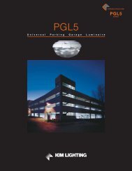
Proportion Guide70 to 400 Watt / 10' to 30' Poles32'RA25HSAS30-64250B30'28'26'This proportion diagram is intended to help visualizeand select the best <strong>Era</strong> system to satisfy aestheticrequirements. Remember, the pole height alsoaffects performance; the higher the fixture ismounted, the greater the light throw. If poles aremounted on concrete pedestals such as in parkinglots, the height of the pedestal must be considered inselecting the pole height.RA25HSAS25-64250B24'22'RA17HSAS20-534188B20'18'RA17HSAS16-534188A16'14'12'RA17HSAS10-534188A10'8'6'4'2'GRADEKIM LIGHTING 29
Lamp and Electrical GuideLampLampWattsANSIBallastTypeLife(Hours)InitialLumens 1VoltageOperatingAmps.OpenCircuitStartingAmps.Max.Amps.HIGH PRESSURE SODIUM70HPS 120 0.81 1.45 0.75 1.45ED-17 Clear 70 S-62 24000 6300 208 0.47 0.85 0.45 0.85Medium Base (RA17 only) 240 0.40 0.75 0.37 0.75277 0.35 0.65 0.35 0.65347 0.30 0.55 0.30 0.55480 4 0.21 0.36 0.21 0.36100HPS 120 1.15 2.20 1.30 2.20ED-17 Clear 100 S-54 24000 9500 208 0.67 1.25 0.75 1.25Medium Base (RA17 only) 240 0.58 1.10 0.65 1.10277 0.50 0.85 0.60 0.85347 0.39 0.70 0.45 0.70480 4 0.29 0.55 0.35 0.55150HPS 120 1.65 2.80 2.00 2.80E-23K Clear 150 S-55 24000 16000 208 0.95 1.60 1.15 1.60Mogul Base (RA25 only) 240 0.83 1.40 1.00 1.40ED-17 Clear 277 0.72 1.25 0.85 1.25Medium Base (RA17 only) 347 0.56 0.92 0.52 0.92480 4 0.42 0.70 0.50 0.70250HPS 120 2.50 1.70 1.65 2.50E-18 Clear 250 S-50 24000 29000 208 1.50 1.00 0.95 1.50Mogul Base (RA25 only) 240 1.30 0.85 0.80 1.30277 1.10 0.75 0.70 1.10347 0.93 0.70 0.60 0.93480 0.63 0.45 0.40 0.63400HPS 120 3.80 2.00 3.30 3.80E-18 Clear 400 S-51 24000 51000 208 2.20 1.20 1.80 2.20Mogul Base (RA25 only) 240 1.90 0.95 1.50 1.90277 1.70 0.85 1.40 1.70347 1.32 0.70 1.00 1.32480 0.97 0.55 0.75 0.97PULSE START METAL HALIDE100PMH 5 120 1.15 2.60 1.15 2.60ED-17 Clear 100 M-90 10000 7800 208 0.66 1.50 0.66 1.50Medium Base (RA17 only) 240 0.58 1.30 0.58 1.30277 0.50 1.15 0.50 1.15347 0.40 1.00 0.40 1.00480 4 0.31 0.62 0.25 0.62150MH 5 120 1.60 3.65 0.95 3.65ED-17 Clear 150 M-102 15000 14400 208 0.90 2.10 0.55 2.10Medium Base (RA17 only ) 240 0.80 1.80 0.50 1.80277 0.70 1.58 0.42 1.58347 0.55 1.25 0.65 1.25480 4 0.45 1.00 0.30 1.0030 KIM LIGHTING
5CAUTION: All manufacturers of metal halide lamps recommendturning them off for 15 minutes once per week when undercontinuous operation. This will reduce the risk of arc tube rupture atend of life. Also, color temperature may differ betweenmanufacturers of metal halide lamps. See lamp manufacturers’specification sheets.LampLampWattsANSIBallastTypeLife(Hours)InitialLumens 1VoltageOperatingAmps.OpenCircuitStartingAmps.Max.Amps.PULSE START METAL HALIDE 3175PMH 2 120 1.80 1.80 0.95 1.80ED-28 Clear 175 M-137 15000 17500 208 1.05 1.05 0.55 1.05Mogul Base (RA25 only) 240 0.90 0.90 0.45 0.90ED-17 Clear 277 0.80 0.80 0.40 0.80Medium Base (RA17 only) 347 0.65 0.65 0.30 0.65480 0.45 0.44 0.26 0.45250PMH 120 2.50 1.40 1.90 2.50ED-28 Clear 250 M-138 15000 26300 208 1.45 0.80 1.10 1.45Mogul Base (RA25 only) 240 1.25 0.70 0.96 1.25277 1.10 0.65 0.85 1.10347 0.90 0.50 0.62 0.90480 0.57 0.48 0.21 0.57400PMH 120 4.00 3.00 3.50 4.00ED-28 Clear 400 M-135 20000 44000 208 2.30 1.15 2.00 2.30Mogul Base (RA25 only) 240 2.00 1.00 1.75 2.00277 1.75 0.85 1.50 1.75347 1.40 0.70 1.20 1.40480 1.00 0.55 0.90 1.001All initial lumen values shown may vary, due to operating orientation (vertical / horizontal), and from one manufacturer to another. Consult lamp manufacturer’s datafor exact lumen and life data.2175W pulse rated lamps are for use in vertical lamp luminaires only.3Data provided is extracted from Venture Uni-Form product information.4480 volt with medium base lamp sockets may require approval by the local building code authority.NOTE: For lamp/ballast information outside of the U.S.A. and Canada, please consult your local <strong>Kim</strong> representative.WARNING: All fixtures must be grounded in accordance with local codes or the National Electrical Code. Failure to do so may result in seriouspersonal injury.Lamps by others.Application Engineering ServicesApplications Assistance<strong>Kim</strong> <strong>Lighting</strong> utilizes the latest computer technology and softwareto provide specifiers with reliable evaluations of lighting systemperformance. We can analyze a proposed luminaire layout orprovide recommendations based on performance criteria.Electronic copies of plans can be sent directly toyyeager@hubbell-ltg.com. Hard copies can be sent by fax at864-678-1743, or they can be mailed to Applications Dept,701 Millennium Blvd, Greenville, SC 29607.Photometric Files<strong>Kim</strong> <strong>Lighting</strong> .ies format photometric files are available for use inlighting calculation software. The complete IES File Library is onthe internet at www.kimlighting.com.KIM LIGHTING 31
<strong>Era</strong> ®Heritage Style LuminaireBecause of a continuing product improvementprogram, <strong>Kim</strong> <strong>Lighting</strong> reserves the right tochange specifications without notice.How may we serve you better?Let us know by visiting our web site at:www.kimlighting.comYour input is valuable to us.Hubbell<strong>Lighting</strong>, Inc.