

Transformer Moisture Management System ... - Drykeep USA
Transformer Moisture Management System ... - Drykeep USA
Transformer Moisture Management System ... - Drykeep USA

You also want an ePaper? Increase the reach of your titles
YUMPU automatically turns print PDFs into web optimized ePapers that Google loves.
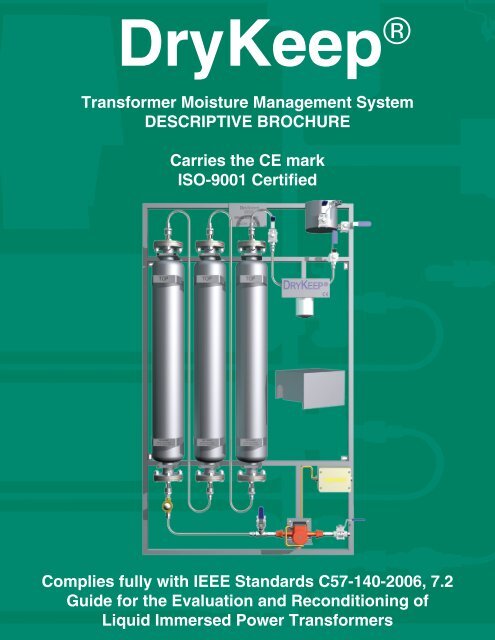
DryKeep ®<br />
<strong>Transformer</strong> <strong>Moisture</strong> <strong>Management</strong> <strong>System</strong><br />
DESCRIPTIVE BROCHURE<br />
Carries the CE mark<br />
ISO-9001 Certified<br />
Complies fully with IEEE Standards C57-140-2006, 7.2<br />
Guide for the Evaluation and Reconditioning of<br />
Liquid Immersed Power <strong>Transformer</strong>s
MODEL RT-3
DryKeep ® Descriptive Brochure January 2012 1 of 15<br />
1.1 INTRODUCTION<br />
Several factors shape the life expectancy of a transformer. One such factor, the moisture content<br />
within a transformer, has a significant detrimental impact on the aging of transformers. It is for<br />
this reason that the reduction of moisture or prevention of moisture increase in a transformer has<br />
captured the attention of all involved in transformer maintenance. Unlike the existing techniques,<br />
which remove moisture after it has already accumulated in the transformer, the DryKeep ® unit<br />
performs this function on an ongoing, proactive basis, effectively slowing down the aging<br />
process.<br />
The main advantage of the DryKeep ® unit lies within continuous moisture management, as<br />
opposed to the very rapid traditional drying methods. By implication, the DryKeep ® unit has a<br />
less dramatic impact on the transformer, as it can safely dry the oil while the transformer is still<br />
on load.<br />
The system is comprised of one or three (depending on the model) completely passive cylinders.<br />
Each cylinder contains a high technology adsorbent material designed to remove the dissolved<br />
water from the oil that passes through the cylinder. As moisture migrates from the transformer<br />
insulation to the oil it is gently removed by the DryKeep ® system on a continuous basis as the oil<br />
passes through the cylinders. The system is unique in that, unlike similar drying techniques, the<br />
moisture that is removed cannot be released back into the oil under normal service temperature<br />
changes, nor can it freeze under severe cold ambient conditions as the adsorbent material can<br />
only release the moisture when heated to 180° C.<br />
The RT 3 and RT 9 models are built on to a standard frame and the installation for both of these<br />
units is similar.<br />
DryKeep ®<br />
CAT #<br />
# OF<br />
CYLINDERS<br />
SUGGESTED<br />
TRANSFORMER<br />
SIZE<br />
WATER REMOVAL<br />
CAPACITY<br />
RT 3 1 LESS THAN 10MVA ± 3 LITRES<br />
RT 9 3 10 MVA AND UP ± 9 LITRES<br />
Each cylinder can remove three liters of moisture and the saturated cylinders are changed under<br />
load.<br />
1.2 APPLICATION OF THE DryKeep ® SYSTEM<br />
1.2.1 TRANSFORMERS<br />
New <strong>Transformer</strong>s<br />
After manufacture, the total moisture content in new transformers is typically less than 0.5%. The<br />
DryKeep ® will maintain this moisture content and eliminate moisture buildup.<br />
Repaired <strong>Transformer</strong>s<br />
After a major overhaul in a workshop, and after having undergone a vapor-phase treatment, the<br />
moisture content of a repaired transformer is similar to that of a new transformer (≥ 0.5%).<br />
Therefore, the application is the same as for new transformers.<br />
In-Service <strong>Transformer</strong>s<br />
<strong>Transformer</strong>s, irrespective of age, should be fitted with a DryKeep ® to reduce the moisture in the<br />
transformer and eliminate moisture buildup. <strong>Transformer</strong>s that have been in service for many<br />
years typically have high moisture content (2% and beyond). The objective is to reduce the<br />
moisture content of the paper insulation to an acceptable level and then maintain that level. This<br />
will substantially increase the life of the transformer. A transformer has to be assessed to<br />
determine its total moisture content and a moisture reduction plan must be established. Before<br />
installing DryKeep ®<br />
on the transformer(s), DryKeep <strong>USA</strong> will estimate the amount of moisture in
DryKeep ® Descriptive Brochure January 2012 2 of 15<br />
the paper insulation. We will request certain information regarding the transformer characteristics<br />
to determine the moisture content. We will advise how many changes of saturated cylinders will<br />
be required before reaching a predetermined safe level which is about 1.3% moisture by weight<br />
remaining in the paper. The transformers are dried down to a safe level to avoid re-clamping of<br />
the core and coil assembly as it is not always possible to re-clamp in the field. The dry-out<br />
process must be monitored periodically by assessing the moisture content of the transformer.<br />
The moisture content and size of the transformer will affect the number of cylinder replacements<br />
required and the total amount of time to dry out the transformer to a safe level.<br />
1.2.2 STORAGE TANKS CONTAINING TRANSFORMER OIL<br />
Installation of DryKeep ® is recommended to reduce moisture content to a sufficiently low level in<br />
storage tanks containing high levels of moisture (>2%), or to maintain moisture content and<br />
eliminate buildup in storage tanks with very little moisture content.<br />
1.3 DryKeep ® SYSTEM DESCRIPTION<br />
(Refer to section 6 below, which identifies the various main components of the DryKeep ® system)<br />
The DryKeep ® system complies fully with IEEE Standard C57-140- 2006, section 7.2 and is<br />
manufactured under an ISO 9001 quality management system.<br />
The system continuously circulates transformer oil and dries it through moisture adsorption by a<br />
molecular sieve granular adsorbent material contained in the cylinders. The transformer oil is<br />
circulated through the system without heating by a small electric pump and remains at the same<br />
temperature and pressure conditions as the transformer.<br />
The system can contain either one or three cylinders, depending on transformer size. Self-sealing<br />
hydraulic quick couplers are used to connect the cylinders to the pipe-work. Pipe connections<br />
are either screwed or welded. Screwed connections are factory sealed with a sealing agent<br />
(Locktite) that can be unscrewed if required. Welds are dye-penetrated and pressure tested for<br />
leaks. The cylinders, pipe-work, valves, de-aerator, and frame are manufactured from shot blasted<br />
300 series stainless steel, providing a matte gray finish. The material is durable and able to easily<br />
withstand extreme summer and winter temperatures (-40° C to 50° C ambient), as well as harsh<br />
coastal environmental conditions.<br />
The flow indicator is made of gunmetal with a brass cover ring and sight-glass. The particulate,<br />
spin-on oil filter prevents particle carry-over to the transformer but is too small to act as a sludge<br />
filter for the transformer. If a transformer contains sludge this must be removed with a prefiltration<br />
system.<br />
The centrifugal pump is an electrical canned rotor type. The pump and motor form an integral<br />
unit without shaft seal and requires only two gaskets for sealing. This prevents oil leaks to the<br />
environment. The pump cover is attached after installation. There are no pressure hazards as the<br />
pump is self-limiting in pressure and the system input and output are connected to the<br />
transformer, which is exposed to ambient atmospheric pressure. The DryKeep ® system is<br />
completely filled with incompressible low vapor pressure oil.<br />
The maximum operating temperature is 110° C. A typical flow rate of 24 gallons per hour has<br />
been measured depending on the viscosity of the oil.<br />
The DryKeep ® shares the same safety envelope as the transformer as it is installed onto or<br />
adjacent to the transformer. As such, safety precautions pertaining to oil contact with skin and<br />
eyes must be taken in accordance with safety data sheets and the required personal protection<br />
equipment must be used.
DryKeep ® Descriptive Brochure January 2012 3 of 15<br />
1.4 Dry Keep ® FLOW DIAGRAM<br />
The diagram below represents the oil flow directions of the DryKeep ® .<br />
VESSELS<br />
1.5 FEATURES<br />
CONNECTING PIPES<br />
� The cylinders are not pressure vessels<br />
� The operating pressure of 100kPa vacuum (1.2 Bar) is compounded from:<br />
- A static head of 5 meters to the top of the main tank of the transformer (=50<br />
kPa gauge)<br />
- Pump differential pressure (=70kPa)<br />
� Pump is rated at 1 mPa gauge (10 Bar)<br />
� Maximum pressure by volume ratio is 100 Bar. Liter<br />
� The flow indicator is designed for an operation pressure of 0.7mPa (7 Bar) and is<br />
pressure-tested at 1 mPa (10 Bar)<br />
� The quick-couplers are designed for 25mPa (250 Bar)<br />
2. INSTALLATION<br />
PUMP<br />
DE-AERATOR<br />
PARTICLE FILTER<br />
INLET<br />
OUTLET<br />
The DryKeep ® RT 3 and RT 9 system is dispatched filled with oil and fully assembled on the<br />
framework, together with all of the components. The installation thereof is fairly easy.<br />
For detailed installation instructions, please turn to Appendix A at the end of this brochure.<br />
SAFETY NOTE: It is recommended that the transformer be de-energized when installing the<br />
DryKeep ® system. Once in operation, the replacement of the saturated cylinders can be done<br />
with the transformer energized.
DryKeep ® Descriptive Brochure January 2012 4 of 15<br />
3. OPERATION AND MAINTENANCE<br />
The DryKeep ® frame, cylinders and pipe-work are 300 series stainless steel which requires<br />
minimal maintenance.<br />
Once the system is in operation, only periodic inspection is required to check for unforeseen oil<br />
leaks and normal operation of the system.<br />
Oil sampling and saturation assessments with moisture sensors are used to determine the<br />
condition of the molecular sieve in the cylinders. The frequency of sampling is recommended as<br />
follows:<br />
- The first sample should be taken prior to commissioning;<br />
- Thereafter, sampling should be taken after 1, 3, and 6 months have passed;<br />
- Thereafter, sampling should be done as dictated by normal company<br />
maintenance standards and policies.<br />
For detailed operations and maintenance, please refer to Appendix B at the end of this brochure.<br />
4. SATURATION OF CYLINDERS AND REPLACEMENT<br />
There are several methods of determining whether the cylinders are saturated and need to be<br />
replaced.<br />
- Karl Fischer titration testing comparing oil samples taken from the inlet bypass<br />
valve (BP1) and the outlet bypass valve (BP2) or the bleed valve (V5), all as<br />
shown in Section 6 below.<br />
- Portable moisture sensors such as the Doble Domino USS or Vaisala MM70 at<br />
the inlet and outlet bypass valves.<br />
- Permanently mounted moisture monitors taking readings from the inlet and<br />
outlet bypass valves.<br />
Normally, the moisture values between the inlet and outlet will largely differ. As the cylinder<br />
approaches saturation, the inlet and outlet moisture values will converge indicating it is time for<br />
cylinder replacement.<br />
For detailed instructions on cylinder replacement, please refer to Appendix C at the end of this<br />
brochure.<br />
5. THE EFFECT OF THE DryKeep ® ON THE RESULTS OF<br />
DISSOLVED GAS ANALYSIS (DGA)<br />
Dissolved Gas Analysis (DGA) is widely used as one of the tools to carry out condition monitoring<br />
on transformers and has become a useful early warning system to eliminate catastrophic failure.<br />
To ensure the integrity of DGA trending, the molecular sieve beads in the DryKeep ® cylinders are<br />
carefully selected for their preferential bonding with water molecules while excluding bonding<br />
with gas molecules.<br />
During the development of the DryKeep ® system, Eskom Research Institution (TSI) carried out an<br />
investigation on transformers ranging in size from 40 MVA to 500 MVA to determine if DryKeep ®<br />
had any appreciable effect on the interpretation of the DGA. Their conclusion stated that for a<br />
continuously gassing transformer, the action of the DryKeep ®<br />
can never mask the generation of<br />
gas and will not significantly affect a trending analysis of gas production rates.
DryKeep ® Descriptive Brochure January 2012 5 of 15<br />
6. LAYOUT OF THE DryKeep ® RT 9<br />
V1-Inlet Valve<br />
V2- Outlet Valve<br />
V3-Particle Filter Valve<br />
V4-Alternative Outlet Valve<br />
V5 -Bleed Valve<br />
BP1 & BP2-Bypass Valves (for moisture content sampling)
DryKeep ® Descriptive Brochure January 2012 6 of 15<br />
7. DryKeep ® Advantage over Temporary Portable<br />
Devices<br />
The life of a transformer is dependent on the condition of the cellulose insulation and the amount<br />
of moisture that is present in the oil and cellulose insulation system. Proactive measures to<br />
remove the moisture continuously allow the overall moisture level in the transformer to be<br />
controlled more effectively. Permanently installed online moisture dryout systems that gently<br />
remove moisture continuously are preferred to the more aggressive interactive systems that are<br />
used at prescribed intervals. Prevention is ultimately better than a cure. With chemical reactions<br />
always taking place inside a transformer that eventually produce moisture, and the natural affinity<br />
paper has for moisture, prevention is the key to maintaining the integrity of the transformer’s<br />
insulation system. A small investment for prevention can save a large cost for a later major<br />
intervention or “cure”. Ideally it is best to keep a transformer dry, hence the DryKeep ® Online<br />
<strong>Moisture</strong> <strong>Management</strong> system.<br />
However, I want to be absolutely sure I do not over-dry my transformer.<br />
Over-drying the insulation has been a concern of some operators, however, over-drying of a unit<br />
while using a DryKeep ® system is highly unlikely as the transformer insulation system will<br />
ultimately reach a state where there is very little or no transfer of moisture. The drier the<br />
insulation gets the more difficult it will be to remove the moisture. Thus at the outset, the<br />
DryKeep ® will remove a lot of moisture with little effort, but as the insulation dries out there is less<br />
moisture to remove and you reach a state whereby the insulation will no longer release moisture<br />
to the oil no matter how dry the oil may be. The insulation will hold onto the moisture and<br />
likewise, the oil will not give off any moisture. It must be remembered that the DryKeep ® will only<br />
remove the available moisture. The only other factors that will affect the system’s available<br />
moisture are temperature and vapour pressure. The vapour pressure remains fairly constant.<br />
To further ensure that over-drying cannot occur, the DryKeep ® <strong>Moisture</strong> <strong>Management</strong> system can<br />
be supplied with an optional Doble Domino or Vaisala instrument package at the inlet and outlet<br />
by-pass valves. The instruments are moisture-in-oil monitors that simultaneously measure the<br />
temperature and water activity (derivative of relative saturation). Each instrument has two (2) zero<br />
to 20mA analog outputs. Using a simple PLC, you can shut down the DryKeep ® after a specific<br />
ppm reading has been attained and have it restart after the moisture builds up again. Using the<br />
output data obtained from the Doble or Vaisala moisture probe located at the inlet of the DryKeep ®<br />
unit, you can program the PLC to activate a relay when the moisture level reaches 2 ppm or less.<br />
The relay will signal the pump motor to shut off. You then program the PLC to restart the pump<br />
motor after a certain timeframe that is determined by the size and age of the transformer. This<br />
time period can vary from say one month to 3 months. Once the pump restarts, the moisture<br />
monitors will start measuring again. If the transformer oil is still dry, the unit will switch off again<br />
and wait for the next window period to trigger the cycle. However, after restart, the PLC must be<br />
programmed to record several ppm values over a short period time before shutting down the<br />
motor as a single ppm reading is not reliable.
DryKeep ® Descriptive Brochure January 2012 7 of 15<br />
8 WARRANTY<br />
The warranty is valid for a period of twelve months from the date of installation or eighteen months<br />
from the date of shipment, whichever is the earlier.<br />
9. CONTACT US<br />
Headquarters:<br />
DryKeep ® <strong>USA</strong> division<br />
The Ardry Group<br />
195 Industrial Boulevard<br />
Rincon, GA 31326<br />
Tel: (912) 754-2474<br />
Fax: (912) 754-2482<br />
Ed Vance, Sales Manager, phone extension 190<br />
E-mail: edv@ardry.com<br />
Branch Sales office:<br />
DryKeep ® <strong>USA</strong><br />
5 Maggie May Way<br />
Cold Spring, NY 10516<br />
Tel: (845) 809-5726<br />
Joseph W. Carbery, President<br />
E-mail: joec@ardry.com<br />
www.drykeep.com
DryKeep ® Descriptive Brochure January 2012 8 of 15<br />
APPENDIX A<br />
INSTALLATION INSTRUCTIONS<br />
The DryKeep ® system is dispatched from the factory as a fully assembled system on its frame as<br />
shown in the Section 6 layout. It comes filled with transformer oil and the molecular sieve<br />
adsorbent beads. The unit can be mounted as received, or the cylinders can be removed prior to<br />
mounting to lighten the weight of the unit while the rest of the components are to be left on the<br />
framework.<br />
Mount unit at least 20” (500mm) above ground level.<br />
Mounting position should preferably be on the side of the main tank or the coolers / radiators.<br />
The DryKeep ® system must be mounted vertically (inlet valve and pump located at the bottom and<br />
de-aerator at the top).<br />
Fastening of the DryKeep ® frame to the transformer can be done by welding or bolting to the<br />
transformer.<br />
The system can also be mounted onto another structure close to the transformer such as a<br />
building wall or steel structure.<br />
NOTE: When installing the DryKeep ® system on a reactor, DryKeep ® should be mounted on a<br />
free standing frame or an adjacent structure due to excessive vibration interference from the<br />
reactor with the DryKeep ® pipe work and connections. If mounted directly to the reactor tank, we<br />
suggest using vibration dampers. Contact us for further details.<br />
FOR TRANSFORMERS THAT ARE IN SERVICE:<br />
(Refer to the DryKeep ® layout in Section 6 above and sample installation photos below)<br />
<strong>Transformer</strong> should be switched off and made safe before installation commences.<br />
Installation is flexible depending on the transformer design, however the simplest way to install<br />
the DryKeep ® system is to connect the bottom drain valve of the transformer to the DryKeep ®<br />
pump inlet valve V1 (as shown in the layout in Section 6). For added flexibility, DryKeep ® has two<br />
outlet valves that can be selected by the user. Whichever outlet valve is selected (either V2 or V4<br />
as shown in Section 6) will then be connected to the transformer fill valve. The required piping<br />
shall be ½” NPT stainless steel and/or flexible hose (not supplied).<br />
FOR TRANSFORMERS THAT ARE NOT IN SERVICE:<br />
For transformers under repair and/or not containing oil, and thus completely accessible,<br />
modifications can be made to the transformer tank to add an entry and exit fitting for the<br />
DryKeep ® system. The entry and exit fittings need to be diagonally apart from each other (i.e. if<br />
top left, then bottom right) to avoid re-circulating the just-dried oil. If this is not an option,<br />
DryKeep ® can still be installed on a transformer that is not in service the same way as described<br />
above for a transformer in service.<br />
ELECTRICAL CONNECTIONS:<br />
The installer must connect the chosen power supply to the supplied electrical junction box. The<br />
junction box is equipped with terminal blocks and a circuit breaker. The pump is a single phase<br />
120 V, 0.94A max or 220 V, 0.51A max, 60 Hz., or a 230 V, 50 Hz. 1.04A max at speed position three.<br />
The brown lead is the “source” or live line. The blue wire is the neutral and the yellow/green wire<br />
is the ground.
DryKeep ® Descriptive Brochure January 2012 9 of 15<br />
MECHANICAL CHECKS:<br />
The installer should check the tightness of all cylinder bolts (torque value of 65 lb-ft. or 88<br />
Newton/meters), and check that the quick couplers are secured.<br />
COMMISSIONING:<br />
Once the system is mounted, piped to the transformer, and an available power supply has been<br />
provided to the pump motor via the electrical junction box, the system is ready for<br />
commissioning.<br />
The following procedure must be adhered to in order to prevent air from entering the transformer:<br />
1. Ensure that the active outlet valve (either V2 or V4 as shown in the layout in Section 6) on<br />
the DryKeep ® system is closed.<br />
2. Open the inlet valve (V1) of the DryKeep ® system and start the pump.<br />
3. Slowly open the bleed valve (V5) on the de-aerator tank. It is recommended that the<br />
installer has a vessel on hand at this step to capture any oil that may come out of the<br />
bleed valve while it is open.<br />
4. Ensure that all the trapped air in the system escapes through the bleed valve.<br />
5. Close the bleed valve on the de-aerator tank (V5).<br />
6. Slowly open the active outlet valve (V2 or V4) of the DryKeep ® system.<br />
7. Open the bleed valve (V5) intermittently to remove air from the system that collects in the<br />
top of the de-aerator. Again, it is recommended that the installer has a vessel on-hand at<br />
this step to capture any oil that may come out of the bleed valve while it is open.<br />
8. Monitor the system closely for 20 minutes and check for oil leaks and oil flow through the<br />
flow indicator and for any abnormalities.<br />
Once installed and commissioned the system will operate continuously.<br />
Regular visual inspections must include:<br />
- Checking for leaks<br />
- Check if flow indicator turns<br />
- Check if pump is operating<br />
Troubleshooting:<br />
If a leak is detected on the cylinder flanges, check to ensure that the bolt torque is at 65 lb-ft (88<br />
Newton-meters.<br />
If the flow indicator is not turning but the pump is operating, first tighten all quick couplers to<br />
ensure that the annular ball valve has been released. If the flow indicator is still not turning,<br />
slightly loosen the flow indicator glass cover as it may be impeding the impeller rotation. If the<br />
flow indicator still does not turn, the particle oil filter cartridge could be blocked and may require<br />
replacement.<br />
If the pump is not operating, check for an electrical fault.
DryKeep ® Descriptive Brochure January 2012 10 of 15<br />
TYPICAL INSTALLATION AT THE TRANSFORMER DRAIN VALVE<br />
ALTERNATE INSTALLATION TO DRAIN VALVE
DryKeep ® Descriptive Brochure January 2012 11 of 15<br />
APPENDIX B<br />
OPERATION AND MAINTENANCE INSTRUCTIONS<br />
After commissioning of the DryKeep ® system, only periodic inspections are required to check for<br />
unforeseen oil leaks and normal operation.<br />
PERIODIC CHECKS:<br />
Check for any oil leaks – tighten bolts if required (cylinder flange bolt torque must be 65 lb-ft or 88<br />
Nm); tighten particle oil filter cartridge if leaking.<br />
Check for pump operation – an inoperative pump could be caused by an electrical defect.<br />
Check for flow at the flow indicator – lack of flow may indicate a blocked oil filter or pump not<br />
operating. Glass cover of flow indicator may be too tight, impeding the movement of the paddle<br />
wheel. Loosen glass very slightly.<br />
Check for tightness of all quick couplers. If not tight, the built-in annular ball valve may not open.<br />
TROUBLESHOOTING:<br />
The most probable conditions that could occur are a leak at a flange gasket, connection, or joint,<br />
clogging of the particle oil filter, or malfunctioning of the pump.<br />
If a leak is detected on the cylinder flanges, check to ensure that the bolt torque is at 65 lb-ft (88<br />
Newton-meters.<br />
If the flow indicator is not turning but the pump is operating, first tighten all quick couplers to<br />
ensure that the annular ball valve has been released. If the flow indicator is still not turning,<br />
slightly loosen the flow indicator glass cover as it may be impeding the impeller rotation. If the<br />
flow indicator still does not turn, the particle oil filter cartridge could be blocked and may require<br />
replacement.<br />
Particle Oil Filter Cartridge Replacement:<br />
To replace the particle oil filter cartridge, shut off the pump and close the V1 inlet and V2 or V4<br />
active outlet valve as well as the V3 valve below the de-aerator.<br />
Use a small bucket to reclaim any oil spills from the pipes during the filter change. Unscrew the<br />
cartridge counter-clockwise and dispose of oil in the cartridge by inverting it over the bucket.<br />
Dispose of the cartridge. Replace the cartridge by clockwise screwing on a new one. Wipe the<br />
cartridge and surrounding pipe-work clean of oil with a cloth. Open the V1 inlet valve and the V3<br />
valve underneath the de-aerator. Start the pump. Open the V5 bleed valve on the de-aerator,<br />
throttle and close after all air has escaped. Monitor the system closely for 20 minutes and check<br />
for oil leaks and flow through the flow indicator and for any abnormalities.<br />
NOTE: If the DryKeep ® has to be isolated for any reason, the inlet valve V1 should remain open<br />
and close the active outlet valve V2 or V4 and isolate the pump. The V1 inlet valve is left open to<br />
allow for thermal expansion of the oil inside the DryKeep ® .<br />
If a vacuum is to be applied to the transformer, the DryKeep ® must be isolated.
DryKeep ® Descriptive Brochure January 2012 12 of 15<br />
APPENDIX C<br />
CYLINDER REPLACEMENT INSTRUCTIONS<br />
Once the cartridges have been saturated with moisture they need to be replaced with new or<br />
regenerated cartridges. The following procedure must be followed:<br />
1. Isolate the electrical supply to the pump.<br />
2. Close inlet valve (V1) at the bottom of the DryKeep ® system<br />
3. Close the active outlet valve (V2 or V4) at the top of the DryKeep ® system.<br />
4. Starting from the left hand cylinder and working towards the right hand cylinder unscrew<br />
(by hand) the top and bottom quick couplers on each cylinder.<br />
5. Disengage the quick couplers by unscrewing and pulling apart in the sequence below:<br />
1 st - bottom of left-hand cylinder.<br />
2 nd - top of left-hand cylinder.<br />
3 rd - bottom of the center cylinder.<br />
Remove connecting pipe<br />
4 th - top of center cylinder.<br />
5 th - bottom of right hand cylinder.<br />
Remove connecting pipe<br />
6 th - top of the right hand cylinder.<br />
6. The quick couplers contain annular ball valves that are self-sealing on removal. Any<br />
cylinder can be removed by removing the clamps. Note that each cylinder weighs<br />
approximately 110 lbs (50kgs), so two persons are recommended for cylinder removal.<br />
Use the two lifting handles on each cylinder.<br />
7. Position the fresh cylinders onto the frame by using the lifting handles and clamps.<br />
8. Replace the pipes by engaging the quick couplers and manually tighten the couplers.<br />
9. The system is now ready to be re-commissioned. The following procedure must be<br />
followed to prevent air from entering the transformer:<br />
a. Open the inlet valve (V1) of the DryKeep ® system and start the pump by switching<br />
on the electrical supply.<br />
b. Slowly open the bleed valve (V5) on the de-aerator tank. It is recommended that the<br />
installer has a vessel on-hand at this step to capture any oil that may come out of<br />
the bleed valve while it is open.<br />
c. Ensure that all the trapped air in the system escapes through the bleed valve.<br />
d. Close the bleed valve on the de-aerator tank (V5).<br />
e. Slowly open the active outlet valve (V2 or V4) of the DryKeep ® system.<br />
f. Open the bleed valve (V5) intermittently to remove air from the system that collects<br />
in the top of the de-aerator. Again, it is recommended that the installer has a<br />
vessel on-hand at this step to capture any oil that may come out of the bleed valve<br />
while it is open.<br />
g. Monitor the system closely for 20 minutes and check for oil leaks and oil flow<br />
through the flow indicator and for any abnormalities.
DryKeep ® Descriptive Brochure January 2012 13 of 15<br />
DryKeep FREQUENTYLY ASKED QUESTIONS<br />
1. DOES DryKeep ® HAVE A MONOPOLY ON THE MOLECULAR SIEVE TECHNOLOGY?<br />
DryKeep ® does not have a monopoly on the Molecular Sieve Technology. The process is<br />
acknowledged by the IEEE <strong>Transformer</strong> Maintenance Committee as a viable method for drying out<br />
transformers. They would never acknowledge a system that was a sole source. (Refer to C57-140-<br />
2006, paragraph 7.2). DryKeep ® happens to be the leader in molecular sieve on-line continuous<br />
drying of both the oil and paper insulation. The success lies in DryKeep ® ’s low cost, low<br />
maintenance and non-invasive method of getting moisture out of the paper insulation where 98%<br />
of the moisture resides. DryKeep ® was developed and manufactured by South African<br />
government agencies, specifically the Nuclear Energy Corporation of South Africa (NECSA) and<br />
Rotek Engineering Division of ESKOM, the 5th largest power company in the world. DryKeep ® has<br />
been in service since 1997 and is installed on over 800 transformers worldwide. Many of the<br />
leading power companies in the world have adopted and even specified that all their new<br />
transformers must have DryKeep ® factory installed.<br />
2. WHEN A TRANSFORMER IS EQUIPPED WITH DRYKEEP, HOW LONG BEFORE THE<br />
MOISTURE LEVEL WILL START TO REDUCE?<br />
DryKeep ® starts reducing the moisture level immediately. How long it takes to dry out the<br />
insulation depends upon the size of the transformer and how wet it was before the DryKeep ® was<br />
installed. For example, a 20 mva transformer probably would dry out in 10 to 12 months. Once<br />
you dry it down to a safe level (~1.3%), you would only need to change the cylinders every 5 or 6<br />
years. Larger transformers could take up to 2 years to dry down to a safe level.<br />
3. HOW DO WE KNOW WHICH ONE OF THE CYLINDERS IS SATURATED?<br />
All 3 cylinders become saturated at the same time and are replaced as a group.<br />
4. HOW AND WHEN DO WE CHECK FOR CYLINDER(S) SATURATION?<br />
DryKeep® can be purchased with an optional moisture measurement instrument package,<br />
installed in a cabinet, which measures both the oil temperature and the parts per million moisture<br />
content of the oil at the inlet and outlet bypass valves of the DryKeep® unit. When the inlet and<br />
outlet ppm readings converge, the cylinders are saturated. Without the optional instrument<br />
package, the customer can use a test instrument, such as the Doble or Vaisala portable unit, to<br />
measure the ppm of moisture in oil at both the inlet and outlet bypass valves. Alternatively, take<br />
an oil sample at the inlet and outlet bypass valves of the DryKeep® and use the Karl Fischer<br />
titration test to determine the ppm moisture content. Always record the top oil temperature when<br />
taking samples for the titration test. Again, when the inlet and outlet ppm readings converge, the<br />
cylinders are saturated.<br />
5. WHAT DO WE DO WHEN THE CYLINDER(S) BECOME SATURATED?<br />
When the cylinder(s) are saturated, they are simply removed while the transformer remains under<br />
load and returned for regeneration. Please refer to Appendix C of this Descriptive Brochure for<br />
more details.<br />
6. HOW OFTEN DO WE NEED TO TAKE OIL SAMPLES/CHECK THE MOISTURE OF THE OIL?<br />
The frequency of oil sampling is recommended as follows:<br />
- The first sample should be taken prior to commissioning;<br />
- Thereafter, sampling should be taken after 1, 3, and 6 months have passed;<br />
- Thereafter, sampling should be done as dictated by normal company<br />
maintenance standards and policies.<br />
7. HOW CAN WE PROVE THAT DryKeep ® IS A COST-WORTHY INVESTMENT WHEN<br />
COMPARED TO A TRANSFORMER WITHOUT DryKeep ® ?
DryKeep ® Descriptive Brochure January 2012 14 of 15<br />
Think of DryKeep ® as an insurance policy for your transformer. Large utilities like ESKOM (South<br />
Africa) have repeatedly installed DryKeep ® on both new and older wet transformers. Experience<br />
has shown that by keeping the moisture in paper at a low level, the life of the insulation increased<br />
ten-fold. The relatively low cost of DryKeep ® compared to the cost of replacing an expensive<br />
transformer more than justifies the relatively small investment.<br />
8. CAN YOU ESTIMATE THE INCREASED LIFE TIME OF A TRANSFORMER (NEW AND OLD)<br />
EQUIPPED WITH DryKeep ® ?<br />
Each transformer will have a different life span based on the frequency and intensity of the<br />
maintenance, ambient temperatures, loading factor, and operating temperatures. We do know<br />
from tests performed by Rotek Engineering of South Africa showed that the life of the paper<br />
insulation is increased ten-fold when a transformer is equipped with DryKeep ® .<br />
9. THE MAINTENANCE INSTRUCTIONS OF DryKeep ® DON’T SPECIFY HOW FREQUENTLY<br />
THE MAINTENANCE PROCEDURE/INSPECTION SHOULD BE DONE SUCH AS ONCE A YEAR OR<br />
TWICE A YEAR...ETC.<br />
We cannot dictate how frequently the customer performs their routine maintenance.<br />
10. PLEASE ADVISE THE CHARACTERISTICS OF THE MOLECULAR SIEVE.<br />
Below is a general description of the product. We cannot divulge the actual size or coatings used<br />
in the manufacturing process. This is proprietary information.<br />
DryKeep ® Molecular Sieve Beads<br />
Molecular sieve beads combine the highly selective adsorption properties of Zeolites with high<br />
mechanical integrity due to advanced manufacturing and de-dusting technologies. After<br />
synthesis, each zeolite crystal is only a few microns across. To be of use in our fixed bed<br />
adsorption processes, it is necessary to form particles in a specific diameter. Expertise in<br />
molecular sieve beading has led to optimized bead properties for the DryKeep ® system. For<br />
regenerative applications like petrochemicals drying with zeolite adsorbents, special binders are<br />
applied; this gives our molecular sieves a high stability against contaminants in the feed stream,<br />
thus allowing a long unit lifetime.<br />
11. IS THE DryKeep ® SYSTEM INSTALLED BY THE CUSTOMER OR BY THE SUPPLIER?<br />
Installation is so simple that typically the customer easily does it themselves. Power companies<br />
prefer not to have strangers working inside their energized substations. They usually have their<br />
own workers do the installation. We provide detailed instructions with each DryKeep ® unit and are<br />
always available for site supervision during installation, or if necessary DryKeep ® <strong>USA</strong> can<br />
arrange for a contractor to do the installation.<br />
12. IS IT NECESSARY TO SHUT DOWN TRANSFORMER WHEN INSTALLING DryKeep ® ?<br />
It is advisable to shut off the transformer, especially when installing the return piping to the fill<br />
valve which is at top area of the transformer. It is not necessary to de-energize the transformer<br />
when replacing the saturated cylinders.<br />
13. HOW DO I KNOW WHEN TO REPLACE THE PARTICLE OIL FILTER?<br />
Most of our customers replace the particle filter when replacing the saturated cylinders or sooner<br />
if the transformer is very old and has dirty oil. Some customers change it during their routine<br />
inspections which occur mostly every 2 to 3 months.<br />
14. HOW WOULD YOU KNOW WHEN THE TRANSFORMER HAS BEEN DRIED DOWN TO THE<br />
SAFE LEVEL?<br />
Before installing DryKeep ® on the transformer(s), we will estimate the amount of moisture in the<br />
paper insulation. We will request information regarding the transformer characteristics that
DryKeep ® Descriptive Brochure January 2012 15 of 15<br />
enables us to determine the moisture content. This allows us to determine how many changes of<br />
saturated cylinders will be required before reaching a predetermined safe level of about 1.3%<br />
moisture by weight that should be left in the paper. The transformers are dried down to a safe<br />
level to avoid re-clamping of the core and coil assembly as it is not always possible to do in the<br />
field. To further ensure that over-drying cannot occur, DryKeep ® can be supplied with an optional<br />
moisture measurement instrument package and, by using a simple PLC, you can program it to<br />
shut down the DryKeep ® pump when the moisture reaches a predetermined level and have it<br />
restart after the moisture builds up again. Refer to Section 7 of this Descriptive Brochure for<br />
additional information.<br />
15. DO TRANSFORMERS NEED ANY ADDITIONAL MAINTENANCE IF EQUIPPED WITH<br />
DryKeep ® ?<br />
The transformer is not adversely affected in any way when DryKeep ® is installed. It is like any<br />
other transformer accessory such as a temperature or pressure gauge installed on a transformer.<br />
DryKeep ® extends the life of the paper insulation ten-fold. It allows the owner to operate it at<br />
higher temperatures and put greater loads on the transformer by maintaining the dielectric<br />
strength of the insulation system.<br />
16. WHAT ARE THE APPLICABLE STANDARDS FOR THE DryKeep ® PRODUCT?<br />
IEEE Standard C57-140-2006, 7.2 written by the IEEE <strong>Transformer</strong> Maintenance Sub-committee.<br />
DryKeep ® complies 100% with all the provisions. It is manufactured under ISO 9001 quality<br />
standards.
DRYKEEP ® <strong>USA</strong><br />
www.drykeep.com<br />
MARKETED & TECHNICALLY SUPPORTED BY:<br />
DryKeep ® <strong>USA</strong>, a division of the Ardry Group<br />
195 Industrial Boulevard<br />
Rincon, GA 31326<br />
Tel: (912) 754-2474<br />
Fax: (912) 754-2482<br />
Contact: Ed Vance<br />
E-mail: edv@ardry.com<br />
NEW YORK OFFICE:<br />
DryKeep ® <strong>USA</strong><br />
5 Maggie May Way<br />
Cold Spring, NY 10516<br />
Tel: (845) 809-5726<br />
Contact: Joe Carbery<br />
E-mail: joec@ardry.com