Installation
Installation
Installation

Create successful ePaper yourself
Turn your PDF publications into a flip-book with our unique Google optimized e-Paper software.
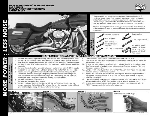
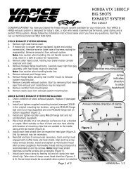
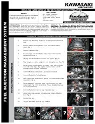
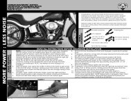
HARLEY-DAVIDSON ® TOURING MODELBIG RADIUSINSTALLATION INSTRUCTIONSPART# 26057MORE POWER : LESS NOISESTOCK EXHAUSTSYSTEM REMOVAL1. Remove both left and right saddlebags and set them aside. Remove right side cover.2. Loosen the pinch clamp bolt on the front end of muffler(s). NOTE: On OE two intoone right side only exhaust systems, there is no left side removal of mufflers required.3. Remove the two 5/16” bolts and washers that mount the muffler(s) to the saddlebagsupports.4. Remove the stock mufflers with sliding hangers and set them aside. NOTE: It may benecessary to use a penetrating lubricant to loosen the muffler from the head pipe.5. Locate and unplug the O2 sensor wires from the wiring harness (Grey and Blackconnectors located behind right side panel) and remove cable ties holding wiresto frame. Feed the end of the wires through the frame so they are free from themotorcycle. NOTE: Pay attention to wire routing for re-installation.6. Remove the right hand floor board.7. Remove both passenger floor boards.8. Loosen head pipe clamp connecting the left side muffler to the header and themount bracket on the backside of the oil pan. Remove the crossover section of headpipe and head pipe clamp (OE dual muffler systems only).TOOLSREQUIREDREAD ALL INSTRUCTIONS BEFORE BEGINNING INSTALLATIONCongratulations, you have purchased the finest exhaust system for yourmotorcycle on the market. Your Vance & Hines exhaust system is designedand crafted for maximum performance, a perfect fit, a great sound andunbeatable style. Please follow the installation instructions below and if youhave any questions, please call our technical support line at (562) 926-5291.Attention installer (if other than owner), please forward this instruction sheetto the owner of this product. These instructions contain valuable informationto the end user.Flat blade screwdriver5/16” Nutdriver1/2”, 9/16” & 14mm Combinationwrenches3/16” & 5/16” Allen wrench9. Loosen the heat shield clamps on both front and rear exhaust pipes.10. Remove the nut and carriage bolt holding the front head pipe to the bracket on thetransmission housing.11. Remove the two mounting nuts from each head pipe, located at the cylinder head.Carefully remove the head pipes and set them aside. This may be easier if the heatshields are loosened first.12. Using a 14mm wrench, carefully remove the O2 sensors from the stock head pipesand save for re-use with the new system.13. Replace the bracket on the transmission housing with new bracket (stamped 508-P)(supplied) and torque to 13-16 ft. lbs. Use ball end of Allen wrench to tightenindicated bolt (Figure 1).14. Carefully remove the exhaust port flanges and circlips from the stock exhaust systemusing snapring pliers. NOTE: If circlips look bent or twisted, replace them.15. Remove stock exhaust gaskets and replace them with included gaskets. V&H kit#22899 (see accessories) is available for future use.FIGURE 1 FIGURE 2 FIGURE 3 FIGURE 4Install 508-P BracketArrows indicate screw head directionInstall circlips and flangesFt./Lbs.Snapring pliersFt./Lb. Torque wrench3/8” Ratchet & Extentions,1/2” Socket,1/2” & 9/16” deepsockets, 1/4” & 3/8”Allen socketsInstall hoseclampsPage 1 of 4Mark mounting cliplocationsD717IN Rev. 1.2
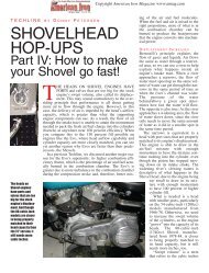
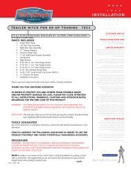
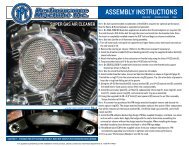
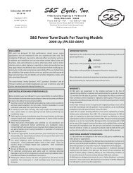
FIGURE 5 FIGURE 6 FIGURE 7 FIGURE 8MORE POWER : LESS NOISEFUELPAK VANCE & HINES EXHAUSTSYSTEM INSTALLATIONInstall nut platesAlign pipes to have a consistent gap1. Remove head pipes and heat shields from protective packaging. Place each heat shieldon a non-abrasive surface such as blanket or carpet. Using a felt tip pen, mark outsideedge of each heat shield to show location of mounting clips that hose clamps will loopthrough (Figure 2).2. Lay head pipes into heat shields and loosely install the #20 hose clamps (supplied) intomounting clips (Figure 3). NOTE: Muffler heat shields will be installed after pipes areon the motorcycle. Screw heads should be accessible when the system is installed onmotorcycle for adjustment purposes (Figure 3). Do not tighten at this time.3. Apply a small amount of anti-seize compound to the threads of the O2 sensors andinstall them into the new head pipes, (Grey connector into front headpipe, Blackconnector into rear headpipe). NOTE: Be careful not to get anti-seize on sensor tip, itmay affect sensor function.4. Install circlips and flanges from stock system onto both new head pipes (Figure 4).5. Using stock flange nuts, carefully install head pipes onto motorcycle. Do not tighten atthis time.6. Use the nut plates and 5/16” x 5/8” flange bolts (supplied) to attach the pipes to thebracket (Figure 5). Do not tighten at this time.7. Align pipes on motorcycle so the gap between the two muffler bodies is consistent fromfront to rear (Figure 6). Tighten the exhaust port flange nuts and the 5/16” x 5/8” flangehead bolts8. Using the #28 hose clamps (supplied) install the muffler heat shields beginning with theD308HC on the front head pipe followed by the D309HC on the rear head pipe. Screwheads should be accessible for adjusment purposes (Figure 4). Do not tighten at thistime.9. Adjust all heat shields for the best alignment at the seam where they meet (Figure 7)and tighten all the hose clamps.10. Install Spacer (593-P), on floor board support plate. Remove the left 3/8” capscrew onlyand place the spacer onto floor board support plate aligning the holes in the spacerwith those on the support plate. Re-install the 3/8” capscrew into the original holesecuring spacer. NOTE: You may use the 3/8”-16 x 1 1/2 bolt (supplied) to temporarilyhold spacer alignment while tightening the 3/8” capscrew.11. Install a 3/8” lock washer (supplied) on both of the 3/8”-16 bolts (supplied). Using thesebolts re-install the floor board using a 3/8”-16 x 3” bolt with TWO spacing washers(supplied) on the forward (right) mount and the 3/8”-16 x 1 1/2” bolt with ONE spacingwasher (supplied) on the rear (left) mount. NOTE: Spacing washers are located betweenthe floor board supports and floor board mount plate. On CVO Models, a 3/8”-16 x1-1/2” socket head cap screw (not supplied) should be used from the inside on the rightmount rather than the 3/8”-16 x 3” provided bolt.12. Re-install the right hand passenger floor board using the supplied relocator bracket(Stamped 579-P), low profile allen bolt and lock washer (supplied). NOTE: This bracketshould only be mounted in the highest possible position on the bike frame, and thefloorboard should be mounted in the upper two bracket holes (Figure 8).13. Re-install left hand passenger floor board. OPTIONAL KIT: If you would like to raisethe left hand passenger floor board to match the right please order Vance & Hines kitnumber 16931.14. Route O2 sensor wires away from hot areas of the motorcycle. Use the nylon cable ties(supplied) to secure the O2 sensor wires to the frame. Plug the O2 sensor wires backinto the wiring harness, grey into grey, black into black. Re-install the right side panel.15. Re-install saddlebags.16. Be sure to tighten all hardware before starting your motorcycle.17. After installation and before starting the motorcycle, completely clean pipes and mufflerswith cleaning solvent and a clean soft cloth that will not leave residue. NOTE: Anyresidue, oil, or fingerprints will stain the chrome when the metal heats up.EXHAUST CARE - HELPFUL HINTS TO AVOID DISCOLORATION OF EXHAUST SYSTEM1. When installing a new set of chrome pipes, make sure your hands are clean and free of oil.After installation, thoroughly clean pipes with a soft cloth and cleaning solvent that will leaveno residue (chrome wax / polish, glass cleaner, alcohol, ammonia, etc...) before starting themotorcycle.2. Avoid long periods of idling as this can cause discoloration.3. Intake leaks can cause the engine to run lean and overheat, this could lead to discoloration.4. Make sure there are no exhaust leaks at the junction of the exhaust pipes and cylinder head.We recommend replacing gaskets if they are worn.VANCE & HINES OPTIONAL ACCESSORIESFUEL MANAGEMENT:Take the guess work out of fuel injection with Fuelpak FuelManagement, P/N 61003. Contact your local dealer orcall (562) 921-0071 to order. Visit fuelpakfi.com for moreinformation.Fuelpak is intended for racing or off-highway use only, and isnot legal for sale or use in California on pollution-controlledvehicles.Check for good alignment at the seam#22899 HD 2010 Exhaust Gasket Kit (pair)Install 579-PPLEASE NOTE: Every effort is made for Vance & Hines Exhaust Systems to provide improved cornering clearance. However, due to design and space limitations on some motorcycle models, ground andcornering clearance may not be improved and in some cases may be reduced. Be sure to follow proper installation instructions.Page 2 of 4D717IN Rev. 1.2
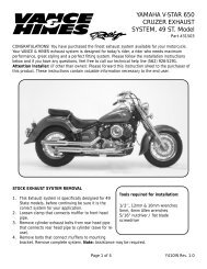
FUEL MANAGEMENTGET THE MOST OUT OF YOUR RIDING EXPERIENCE...AN AFTERMARKET EXHAUST SYSTEM IS ONLY YOUR FIRST STEP, NOW YOU NEED FUEL MANAGEMENT.NOW YOU NEED FUELPAK.MORE POWER : LESS NOISEYour fuel injected Harley-Davidson® is equipped with an ECU (electroniccontrol unit) that’s programmed to deliver fuel to the motor based on anair/fuel ratio for a stock air filter and stock exhaust system. When you installa performance exhaust system, your airflow changes, so you need afuel management system that adjusts your air/fuel ratio to matchthe changes. That fuel management system is Fuelpak. Fuelpakadds and takes away fuel, allowing for a more precise range ofrefinement in your air/fuel ratio. Get the perfect fuel managementcombination with your Vance & Hines exhaust system, get Fuelpak.For more information visit the tuning center at fuelpakfi.comNOTICE: Fuelpak is intended for racing or off-highway use only, and is not legalfor sale or use in California on pollution-controlled vehicles.Page 4 of 413861 ROSECRANS AVENUE / SANTA FE SPRINGS, CA 90670SALES: (562) 921-5388 / TECHNICAL: (562) 926-5291 / FAX: (562) 802-0110VANCEANDHINES.COMD717IN Rev. 1.2
![Powerdrive Left Side Drive 6 Speed Transmission [exploded view]](https://img.yumpu.com/45841241/1/190x245/powerdrive-left-side-drive-6-speed-transmission-exploded-view.jpg?quality=85)