XLS40e/50e/60e System Architecture - The Fire And Security ...
XLS40e/50e/60e System Architecture - The Fire And Security ...
XLS40e/50e/60e System Architecture - The Fire And Security ...
- No tags were found...

You also want an ePaper? Increase the reach of your titles
YUMPU automatically turns print PDFs into web optimized ePapers that Google loves.
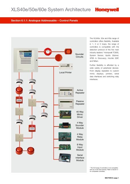
<strong>XLS40e</strong>, XLS<strong>50e</strong> and XLS<strong>60e</strong>Section 6.1.1: Analogue Addressable – Control Panels<strong>The</strong> XLS40, 50 and <strong>60e</strong> range ofintelligent fire alarm control panelshas been designed with opennessin mind. Affording connectionwith up to 5 of the industryleading detection protocols, 4of which are truly open protocol.Constructed around proven andreliable microprocessor technology,the series boasts a vast andcomprehensive range of peripheralsproviding a scalable approach toalmost all applications.l Multi Protocoll TC800l <strong>System</strong> Sensorl Apollo (Xplorer, XP95 andDiscovery)l Hochiki ESPl Nittanl Supports loop poweredSounder Beaconsl Modular conceptl Simple, robust designl Intuitive to usel Cost effective to maintainl Easy to expand – scalablel Network optionsOrder Codes<strong>XLS40e</strong> Single LoopControl Panel 722-101-001XLS<strong>50e</strong> One to Two LoopControl Panel 720-101-001XLS<strong>60e</strong> One to Five LoopControl Panel 721-101-001Loop Driver Card forTC800 (HBS) Protocol 795-070Loop Driver Card for<strong>System</strong> Sensor Protocol 795-068Loop Driver Card for ApolloDiscovery or XP95 Protocol 795-066Loop Driver Card for ApolloSeries 90 or XP95 Protocol 795-048Loop Driver Card forHochiki ESP protocol 795-058-005Loop Driver Card forNittan Protocol 795-044-001Semi Flush Mounting Kitfor <strong>XLS40e</strong> and XLS<strong>50e</strong> 797-061Semi Flush Mounting Kitfor XLS<strong>60e</strong> 797-062Loop driver cards ordered separately,compatible with <strong>XLS40e</strong>, XLS<strong>50e</strong> andXLS<strong>60e</strong> only. For further panel accessoriesplease contact Honeywell Building Solutions.Technical SpecificationModel <strong>XLS40e</strong> XLS<strong>50e</strong> XLS<strong>60e</strong>Loop Capacity 1 loop 1 to 2 loops expandable 1 to 5 loops expandableZonesOperating VoltageMax. PSU RatingStandby BatteriesPower Supply Input(s)Power Supply Output(s)WeightXLS<strong>60e</strong> Multi-protocol <strong>Fire</strong> Alarm Control PanelUp to 20 zones with individual LED indicatorsA maximum 200 can be programmed with up to180 software zones with no LED indication230V 50Hz ac (+10%, -15% voltage tolerance)Up to 80 Zones usingthe 795-077-020 & 795-077-060 zone indicationexpansion modules2.5 Amps totalComprising: Battery Charger: 0.7 Amps Internal & External Loads: 1.8 Amps24V sealed lead acid batteries24V and 7V ac (from integral mains transformer)24V dc nominal (26.5 – 19.5V dc)10 kg without batteries18.5 kg with 2 x 12Ah batteries19 kg without batteries38.2 kg with 2 x 24AhbatteriesOperating Temperature 0ºC to +40ºC 0ºC to +40ºC 0ºC to +40ºCHumidity (max) 85% (non-condensing) 85% (non-condensing) 85% (non-condensing)Relevant Standards EN 54 Parts 2 & 4 EN 54 Parts 2 & 4 EN 54 Parts 2 & 4Approvals LPCB pending LPCB LPCBDimensions (mm)<strong>XLS40e</strong> and XLS<strong>50e</strong>400400135XLS<strong>60e</strong>500500195SECTION 6: page
XLS<strong>60e</strong> Repeater PanelSection 6.1.1: Analogue Addressable – Control Panels<strong>The</strong> compact repeaters areremote units which enhance thedisplay and indicating facilitiesof the XLS40/50/<strong>60e</strong> controlpanels. <strong>The</strong>re are two typesof repeaters available, passivewith indications only and activewith both functional controlsand indication. Both repeatersdisplay the operational state ofthe control panel using the 80character LCD display and the 7LED status indicators.l Functional repeater fitted with:XLS<strong>60e</strong> Active Repeater PanelTechnical SpecificationModel Active PassiveOperating Voltage 18 to 32V dc 18 to 32V dcOperating Current 90mA (Quiescent) 120m (Alarm) 90mA (Quiescent) 120m (Alarm)Terminals Maximum cross section 2.5mm 2 Maximum cross section 2.5mm 2User ControlsLED indicatorsKeyswitch activated – <strong>System</strong> Reset,Sound Alarms, Silence/Resound, Mute,Accept and Self TestN/A<strong>Fire</strong>, Fault, Accepted, Disablement, Silenced, Comms Fail, PowerWeight 1.7 kg (approx) 1.7 kg (approx)Operating Temperature +5ºC to +45ºC +5ºC to +45ºCHumidity 10 to 93% (non-condensing) 10 to 93% (non-condensing)Relevant Standards N/A N/AApprovals N/A N/Allllll<strong>System</strong> ResetSound AlarmsMuteSilence/Re-sound AlarmsAcceptSelf testl Connection afforded via RS485peripheral data busl Affords connection of up to 31repeaters per systeml Backlit adjustable alphanumericdisplayl Discrete, aesthetic designDimensions (mm)253.516550Order CodesXLS<strong>60e</strong>/BR BasePassive Repeater 709-711-001XLS<strong>60e</strong>/FR BaseActive Repeater 709-611-001XLS<strong>60e</strong> Repeater Bezel forsemi-flush mounting 020-600-002Requires RS485 (795-004-001)communication module in Port D and anexternal power source.SECTION 6: page
XLS80e Control PanelSection 6.1.1: Analogue Addressable – Control PanelsAdvanced design and manufacturingtechniques together with Honeywell’s50 plus years of experience atthe forefront of the fire industry,ensure that the XLS80e sets newstandards in areas of functionality,flexibility, user friendliness andreliability. <strong>The</strong> XLS80e is the firstchoice when it comes to smartbuilding integration. Connectivitywith Enterprise Building Integrator(EBI) (see Section 8) affords totalcontrol over your building services.XLS80e Control PanelTechnical SpecificationLoop CapacityExpandable from 2 to 8 loop capacity. Up to 198 loop devices(up to 99 sensors and 99 modules) may be fitted to each analogue loopOutput voltage 22.5 to 26.4VMaximum load 0.5AZones255 fire zones per panelMax. PSU Rating7AWeightStandard 14 kg (approx) (no batteries),Extended – extra depth 20 kg, Back Box Extension – extra depth 5 kgOperating Temperature-5ºC to +45ºCRelative Humidity 5 to 95%Relevant Standards EN 54 Parts 2 & 4Approvals LPCB approved to EN 54 Parts 2 & 4l Seamless integration into EBIl Enhanced Loop Boards provideconnection of more than 512devices per control panell Supports Honeywell’sadvanced detection:l FILTREX – harshenvironment detectorl Loop powered aspiratingmodulel Intrinsically safe equipmentl Laser sensor point detectionl Loop powered sounderbeaconsl 24 and 72 hour standbyl Direct serial connection toXLSPAVA – Public Address andVoice Alarm systeml Peer to peer or master slavenetworkingOrder CodesTC800 protocol onlyXLS80e Two LoopControl Panel 020-692Dimensions (mm)XLS80e Four LoopControl Panel 020-693XLS80e Six LoopControl Panel 020-694XLS80e Eight LoopControl Panel 020-695XLS80e Standard Back BoxFlushing Bezel 020-038-002400XLS80e Loop Booster (boostsloop alarm current) 002-629-100XLS80e Printer kit 010-644-009500153A full range of 19-inch rackmounting assemblies addressesthe needs of more industrial typeinstallations.XLS80e RS485Communications Card 010-479Contact Honeywell Building Solutionsfor further information on available zoneconfigurations and other peripheralequipment.SECTION 6: page
Loop BoosterSection 6.1.1: Analogue Addressable – Control Panels<strong>The</strong> loop booster has beenspecifically designed to provideextra power to a loop in an alarmcondition (e.g. higher currentdevices such as sounders andbeacons). In the event thatmore, higher current devices areadded, the loop booster makesan attractive, cost affectivealternative to that of providingadditional control panels orcabling.Loop BoosterTechnical SpecificationLoop Current Quiescent(no faults)Loop Current Quiescent(maximum)Input voltage1.0mA6.7mA – in alarm the loop booster supplies current to the loop (peak 1.5A)230V ac, ±15%, 48-63HzMax. current consumption 1.6AWeight 3.5 kg (without batteries)Operating Temperature-5ºC to +45ºCRelative Humidity 5 to 95%Relevant Standards EN 54 Part 18ApprovalsLPCB pendingl Expands the capacity of ‘alarm’devices on a loopl Self-contained standbybatteriesl Using 2 x 12V 12 Ah SLAbatteries will provide up to72 hour standbyl Up to 1.5A can be supplied tothe loop in alarml Onboard local LED indicationl Fully monitored locally andfrom the control panelDimensions (mm)365Order CodesLoop Output Booster 002-629-100106Flush Mounting Kit for LoopBooster 020-599-002380SECTION 6: page
10 Reasons to Specify XLSSection 6.1.1: Analogue Addressable – Control PanelsEnterprise1Specialist2Direct3Open4TC8005Scalable6Reduce7Loop8Easy9Peace10Building Integrator (EBI)<strong>The</strong> XLS range of controllers are designed to interface seamlessly withEBI, which is a high performance integration package that gives theuser visibility and full control of the building systems: Intrusion, CCTV,<strong>Fire</strong>, Access Control and Environmental Controls.ApplicationsHoneywell Building Solutions has direct access to Honeywell ownedtechnologies that have been designed to specifically deal with ‘Specialist’applications: Public Address and Voice Alarm (PAVA), high sensitivitydetection, hazardous area detection and alarm indication and harshenvironment detection (areas of high levels of airborne contamination).AccessHoneywell owned technologies have a world wide proven track recordin the fire alarm industry so that the end user will always be dealingdirectly with the solution provider and not a third party distributor.Detection ProtocolOne of a few suppliers that can provide interconnection with openprotocol detection and alarm equipment by using the <strong>XLS40e</strong>, <strong>50e</strong>and <strong>60e</strong> control panels (e.g. <strong>System</strong> Sensor, Apollo, Hochiki or Nittandetection protocol).Detection ProtocolTC800 is a detection and alarm equipment protocol that has been specificallydeveloped for HBS worldwide and is the best way to ensure full compatibilitywith all Honeywell systems providing ongoing solution and support,managed from one point of contact – Honeywell Building Solutions.SolutionsUp to 99 panels (XLS40/50/<strong>60e</strong>) or 32 panels (XLS80e) can benetworked to control large or complex sites. New buildings orextensions are also easily accommodated onto an existing system.incidents and false alarms<strong>The</strong> COPTIR multi criteria device is unique to Honeywell and by utilisingthe following methods of combined detection: Carbon Monoxide,Infrared, Heat and optical smoke detection – four sensors in one – it isdesigned to limit the number of false alarms.Powered Sounder/StrobeLoop powered sounder/strobes save on cabling and interface costswhilst ensuring compliance with the Disability Discrimination Act 1995.to Use Interface<strong>The</strong> XLS80e has a 240 x 64 pixel, 6 line by 40 character displayproviding easily identifiable system messages. <strong>The</strong> intuitive on screenmenu allows the user to control and access important information.of MindEstablished, innovative market leader in fire detection, deliveringindustry leading solutions to ensure reliable detection of real fires andminimal false alarm activations.SECTION 6: page
Introduction to XLS Loop DevicesSection 6.1.2: Analogue Addressable – Detectors<strong>The</strong> XLS range of plug in analogue addressable smoke detectors combines state of the artdesign with micro-processor control and sophisticated processing circuitry to provide fast,efficient fire detection in a wide range of applications.All XLS detectors have two integral LEDs, which provide local visual indication of thesensor status. <strong>The</strong>se LEDs provide a dual function. In the event of an alarm, they areswitched ON continuously, and can also be programmed to either blink when polledby the panel or remain off during normal conditions. In addition to their integral LEDs,XLS detectors can be connected to a remote LED indicator.<strong>The</strong> individual loop address of each XLS detector can be easily set and read, usingthe rotary decade address switches located on the rear of each sensor. <strong>The</strong> useof decimal address codes significantly reduces the potential for incorrect addressselection.Each sensor base includes a tamper resistant option which, when activated, preventsthe removal of the sensor from its base without the use of a tool.Full circuit functionality can be easily confirmed on site by use of the sensor testswitch. This comprises a switch operated by a magnet near the side of the detector.Operation of this magnetic switch simulates the effect of smoke or heat on thedetector, and will generate an alarm response to the fire alarm control panel, makingsystem testing both convenient and simple.Drift compensation and smoothingDrift Compensation and Smoothing eliminate nuisance alarms and providea consistent progressive alarm sensitivity threshold throughout the periodbetween service intervals.Sensor valueEffects of Drift CompensationTime: yearsProcessed versus Unprocessed SignalsProcessedUnprocessedIn many instances thiswill result in an improvedeconomic performancethrough savings in thecost of maintenance byextending the detectorcleaning interval.Intelligent sensorsincorporate enhanceddigital signal processing,eliminating spuriouspeaks.Figure 1Honeywell's range of intelligent devicesuses decimal address switches to definea device’s address between 00 and 99(See Figure 1). This is a simple intuitivemethod, not requiring knowledgeof binary or purchase of specialisedequipment to set addresses.Differences in the protocol betweendetectors and modules allow themto have the same address withoutinterfering with each other, and normallyaddress 00 (the factory default setting)is not used within a system so that thepanel can identify if a device address hasnot been set: Hence a total of up to 198devices – 99 detectors and 99 modules(including call points, sounders, inputand output modules) may be connectedto a loop.PW4 µsAdjusted thresholdsAnalogue sensor valueLow fault thresholdMaintenance levels34 56 34 562 7 2 710 98 10 98TENSUNITSTime: hoursSECTION 6: page
COPTIR Multi-criteria SensorSection 6.1.2: Analogue Addressable – Detectors<strong>The</strong> COPTIR device has been specifically designed to meet two critical life safety issues:Reducing False Alarms and Speed of Response.This plug-in fire detector, availablein TC800 protocol only, combines 4separate sensing elements that workintelligently together as a single unit.l Carbon Monoxide (CO) sensing– using EC cell technology – formonitoring partially combustedproducts from a smouldering fire, forexamplel Infra Red (IR) sensing for measuringambient light levels and flamesignaturesl Optical smoke detectionl Heat detection<strong>The</strong> intelligent monitoring of these fourmajor elements of a fire enables theCOPTIR to respond far more quicklyto an actual fire and yet provide avery high immunity to nuisance alarms.<strong>The</strong> device normally operates at a highimmunity level, changing to become verysensitive to fires when the appropriatecharacteristics are sensed. In this waytransient nuisances are monitored andignored, reducing the false alarm rateand genuine fires are communicatedquicker.Based upon the signals, the sensor isconstantly adapting and is dynamicallyElements of a fireEvery fire has different elements, (particulateand gaseous) to be sensed: a true multi-criteriadevice must be able to sense all elements.changing in accordance with:l Sensor thresholdsl Sensor gainl Time delaysl Sensor combinationsl Sampling ratesl Averaging ratesIn the case of a sensor failure, COPTIRwill change the sensitivity of theremaining sensors as well as indicatinga fault condition.<strong>The</strong> IR light sensor helps the detectorrecognise specific situations such aswelding and makes adjustments rapidlyin order to further reduce the potentialfor false alarms.<strong>The</strong> thermal detection function fusesthermistor technology with a softwarecorrected linear temperature response. Inareas where the normal daytime activitiesare likely to create unwanted alarms, thedetector can be programmed to operate ina “Heat only” mode, automatically revertingto optical-thermal operation during theunoccupied period. <strong>The</strong> COPTIR is thusable to offer exceptional false alarmimmunity and excellent fire detection.Gas in a fireCO and CO 2is also emitted.CoptirPerformance test summarySummary of performance testing of COPTIRversus other technologies.100% 100%90% 90%80% 80%4,000 4,000120 12070% 70%3,500 3,500100 10060% 60%3,000 3,00050% 50%2,500 2,50080 8040% 40%2,000 2,00060 6030% 30%1,500 1,50040 4020% 20%1,000 1,00010% 10%500 50020 200% 0%TF1 TF1 TF2 TF2 TF3 TF3 TF4 TF4 TF5 TF5 TF6 TF60 00TF1 TF1 TF2 TF2TF3 TF3TF4 TF4 TF5 TF5 TF6 TF60BURNING WOODBURNING WOODBURNING WOODSMOULDERING WOODSMOULDERING WOODSMOULDERING WOODSMOULDERING COTTONSMOULDERING COTTONSMOULDERING COTTONBURNING POLYURETHANEBURNING POLYURETHANEBURNING POLYURETHANEFLAMING HEPTANEFLAMING HEPTANEFLAMING HEPTANEFLAMING ALCOHOLFLAMING ALCOHOLFLAMING ALCOHOLC0 2 PPMC0 2 PPMBURNING WOODBURNING WOODBURNING WOODSMOULDERING WOODSMOULDERING WOODSMOULDERING WOODSMOULDERING COTTONSMOULDERING COTTONSMOULDERING COTTONBURNING POLYURETHANEBURNING POLYURETHANEBURNING POLYURETHANEFLAMING HEPTANEFLAMING HEPTANEFLAMING HEPTANEFLAMING ALCOHOLFLAMING ALCOHOLFLAMING ALCOHOLC0 PPMC0 PPM100% 100%80% 80%60% 60%40% 40%20% 20%0% 0%Coptir CoptirPhoto-thermalIon Ion4.0%/ft 4.0%/ft2.7%/ft 2.7%/ft1.7%/ft 1.7%/ftWhite White particles particlesBlack Black particles particlesHeat HeatC0 2 C0 PPM 22 PPM C0 PPM C0 PPM Nuisance Nuisance <strong>Fire</strong> <strong>Fire</strong> Overall OverallSECTION 6: page 10
COPTIR Multi-criteria SensorSection 6.1.2: Analogue Addressable – Detectorsl Unique, true four sensor multicriteriadetectorl Fully integrated Infra RedSensing to support the firealarm decisionl CO gas sensing for fastestresponse to slow developingand smouldering firesl Highest immunity to unwantedalarmsl Available in TC800 protocoll Automatic drift compensationof smoke sensor and CO celll Twin LED indicators providing360º visibilityCOPTIRl Wide temperature rangel Built-in test switchTechnical SpecificationTypeOperating Voltage Range15 to 32V dcMaximum Standby Current200μA at 24V dc (no communications)Maximum Alarm Current7mA at 24V dcOperating Temperature Range-20ºC to +55ºCRelative Humidity15 to 90% (non-condensing)Max Wire Gauge for Terminals 2.5mm 2Weight176g (inc base)ColourIvoryMaterialBayblend FR110IR Limits 0-450 uW/cm 2CO Limits0-500 PPMRelevant StandardsEN 54 Parts 5 & 7, LPS1279ApprovalsLPCBl Stable communication withhigh noise immunityl Compatible with TC800 Looppowered sounder beacons toprovide one location for multicriteriadetection and alarmindicationDimensions (mm)102 66 (in B501 base)Order CodesTC800 Protocol onlyCOPTIR Multi-criteria sensor(IR, CO, Optical and Heat)TC850E1009Standard Sensor Base 14506414-007Standard Sensor Basewith Built-in Isolator 14506414-006Compatible with XLS80e only.SECTION 6: page 11
Smoke DetectorsSection 6.1.2: Analogue Addressable – Detectors<strong>The</strong> low profile, photoelectronicsensor is a plug insmoke detector combininga photo-optical sensingchamber with addressableanalogue communicationsand microprocessor control.Intelligent, drift compensationalgorithms allow the sensorto constantly adjust toits surroundings, therebyreducing false alarms due tocontamination.l Microprocessor precisioncontroll Automatic drift compensationl Enhanced signal processing forimproved stabilityl Extended temperature rangel Twin LED indicators providing360º visibilityl Attractive low profile stylel Available in TC800 or <strong>System</strong>Sensor ProtocolSmoke DetectorTechnical SpecificationTypePhotoelectric Smoke SensorMulti Criteria PhotoelectricSmoke / <strong>The</strong>rmal DetectorOperating Voltage Range 15 to 32V dc 15 to 32V dcMaximum Standby Current 200µA at 24V dc (no communications) 250µA at 24V dc (no communications)Maximum AverageStandby Current300µA (One Communication every 5 seconds with LED blink enabled)Maximum Alarm Current(LED On)7mA at 24V dc7mA at 24V dcApplication TemperatureRange-20ºC to +60ºC-20ºC to +60ºCShort duration & storage -30ºC to +80ºC -30ºC to +80ºCHumidity10 to 93% Relative Humidity (non-condensing)Max Wire Gauge forTerminals2.5mm 2 2.5mm 2Material Bayblend FR110 Bayblend FR110Weight 111g 111gColour Pantone Warm Grey 1C Pantone Warm Grey 1CRelevant Standards EN 54 Part 7 EN 54 Parts 5 & 7Approvals CPD, LPCB, VdS CPD, LPCB, VdSOrder CodesTC800 ProtocolPhotoelectric Smoke SensorTC806E1012M01Multi Criteria PhotoelectricSmoke / <strong>The</strong>rmal Detector TC840ME<strong>System</strong> Sensor ProtocolPhotoelectric Smoke Sensor Multi Criteria PhotoelectricSmoke / <strong>The</strong>rmal DetectorBases – for both protocols2251EM2251TEMStandard Sensor Base 14506414-007Standard Sensor Basewith Built-in Isolator 14506414-006Dimensions (mm)102 43SECTION 6: page 12
Audio and Visual Indication RangeSection 6.1.2: Analogue Addressable – Loop Powered Sounder BeaconsHoneywell presents the latest in proven audio visual technology with a comprehensive rangeof loop powered sounders, beacons and combined sounder beacon units. <strong>The</strong>se devices,available in either an integrated detector base or wall mounted version, have been designed tocater for almost any building application.<strong>The</strong> Loop Powered Audio and VisualIndication range provides:More Devices on a Loopl Reduced current consumptionincreases the amount of deviceson a loop without detriment toperformanceLower Installed Costl Total cost of installation includinglabour, cable and devicesSimplified Installation andSpecificationl Ease of design, specification andinstallation of systemsTechnological Innovationl Developing a ‘technology story’ and‘quantifiable USPs’. This enablesHoneywell to be positioned as aninnovator through the provision ofdifferentiated, systems technologiesand products to the marketWide Range of Devicesl Detector base-mount version,reduces the impact on aestheticswith its unobtrusive designl Wall mount version, designed to fitin, architecturally with a building’sdécorl Wide range of body and lenscolours, to suit the needs ofany ancillary fire alarm systemrequirementFeatures and BenefitsHigh PerformanceAllows more products on a loop. 32tones as standard on all products. Lowcurrent products providing high output:l Significant improvements in currentconsumption providing immediateoption to put more AV devices on aloopl More devices on a loop means lessloop. <strong>The</strong>refore, less associatedcabling and labour costsl Reduces the need for additionalproducts such as the loop boosterand associated product costs andinstallationl Low profile, Surface mounting kits &Weatherproof kits available on all wallmount productsCombined sounder/beacondetector base productsAllows all technologies to be installedat one point, in combination with multicriteriadetectors:l Single address for combinedsounder/beacon units softwareallows combined sounder/beaconsto have one address instead of twol One point of installationFully Approved to CPDFully approved to EN 54 PART 3 & CPDfor use in European UnionIsolated or non-isolated variantsFlexibility for system design:l Cost saving for on-goingmaintenance as building changesl Flexibility for system design atquotation stageAvailable in TC800 and <strong>System</strong>Sensor ProtocolMulti-controller compatibility:l TC800 Protocol fully validated with<strong>XLS40e</strong>, <strong>50e</strong>, <strong>60e</strong> and XLS80e(check for compatible control panelfirmware version)l <strong>System</strong> Sensor Protocol affordsconnection to third party panelmanufacturers for existing servicebusinessSECTION 6: page 14
Wall-mounted SounderSection 6.1.2: Analogue Addressable – Loop Powered Sounder BeaconsReceiving their power from theloop, the wall-mounted soundersmake an excellent alternative toconventionally powered devices.Volume control and toneselection (up to 32 different tonesavailable) can be achieved bysimply selecting the appropriateswitch on the reverse of thesounder.Intelligent Wall Mounted Red SounderTechnical SpecificationMax. wire gauge for screw terminals 2.5mm 2Shallow Base DepthDeep Base DepthIngress ProtectionSounder outputCurrent rating10mm40mmStandard IP44 Optional IP66See Sounder Output and Current Ratings tablefor wall-mounted sounders on page 20Relevant Standards EN 54 Part 3ApprovalsCPD, LPCBOrder CodesTC800 ProtocolDimensions (mm)112 68 111For TC800 models add SSDH- before the<strong>System</strong> Sensor Protocol order code<strong>System</strong> Sensor ProtocolIntelligent Wall MountedRed SounderIntelligent Wall MountedWhite SounderWMSOU-RR-P03WMSOU-WW-P03Intelligent Wall Mounted Red Sounderwith IsolationWMSOU-RR-P04Intelligent Wall Mounted White Sounderwith IsolationWMSOU-WW-P04Bases – fit all modelsDeep Profile Base RedDeep Profile Base Detector WhiteDeep Profile Base Bright WhiteDeep Waterproof Base (IP66) RedDeep Waterproof Base (IP66)Detector WhiteDeep Waterproof Base (IP66)Bright WhiteSDBRSDBDSDBWWDBRWDBDWDBWSECTION 6: page 15
Wall-mounted Sounder BeaconSection 6.1.2: Analogue Addressable – Loop Powered Sounder BeaconsWhere audible indication needsto be supplemented by visualmeans, the combined sounder/beacon device is ideally suited.It draws minimal currentenabling many devices to beconnected to a loop. A range ofcoloured lenses suits almost anyapplication.Order CodesTC800 ProtocolFor TC800 models add SSDH- before the<strong>System</strong> Sensor Protocol order code<strong>System</strong> Sensor ProtocolIntelligent Wall Mounted Sounder BeaconRed Body, Red Lens WMSST-RR-P03Intelligent Wall Mounted Sounder BeaconRed Body, Amber Lens WMSST-RA-P03Intelligent Wall Mounted Sounder BeaconRed Body, Clear Lens WMSST-RC-P03Intelligent Wall Mounted Sounder BeaconWhite Body, Red Lens WMSST-WR-P03Intelligent Wall Mounted Sounder BeaconWhite Body, Amber Lens WMSST-WA-P03Intelligent Wall Mounted Sounder BeaconWhite Body, Clear Lens WMSST-WC-P03Intelligent Wall Mounted SounderBeacon with isolationRed Body, Red Lens WMSST-RRx-P04Intelligent Wall Mounted SounderBeacon with isolationRed Body, Amber Lens WMSST-RAx-P04Intelligent Wall Mounted SounderBeacon with isolationRed Body, Clear Lens WMSST-RCx-P04Intelligent Wall Mounted SounderBeacon with isolationWhite Body, Red Lens WMSST-WR-P04Intelligent Wall Mounted SounderBeacon with isolationWhite Body, Amber Lens WMSST-WA-P04Intelligent Wall Mounted SounderBeacon with isolationWhite Body, Clear Lens WMSST-WC-P04Bases – fit all modelsDeep Profile Base RedSDBRDeep Profile Base Detector White SDBDDeep Profile Base Bright White SDBWDeep Waterproof Base (IP66) Red WDBRDeep Waterproof Base (IP66)Detector WhiteWDBDDeep Waterproof Base (IP66)Bright WhiteWDBWTechnical SpecificationMax. wire gauge for screw terminals 2.5mm 2Shallow Base Depth10mmDeep Base Depth40mmIngress ProtectionStandard IP44 Optional IP66Sounder outputSee Sounder Output and Current Ratings tableCurrent ratingfor wall-mounted sounders on page 20Relevant Standards EN 54 Part 3ApprovalsCPD, LPCBDimensions (mm)Intelligent Wall Mounted Sounder Beacon with Red Body and Red Lens112 68 111SECTION 6: page 16
Wall-mounted BeaconSection 6.1.2: Analogue Addressable – Loop Powered Sounder BeaconsWhere audible indication isinsufficient to alert occupantsto a fire condition, with a widerange of coloured lenses to suitalmost any application, the lowcurrent loop powered beaconwill provide a visual means ofidentification. In addition, if usedwith the IP66 mounting baseand gasket, this device couldbe used externally as a moreenvironmentally-friendly meansof communicating betweenbuildings.Intelligent Wall Mounted Beacon with Red LensTechnical SpecificationBeacon type non isolation with isolationVoltage 15 24 15 24Average Current /mA 2.67 1.70 2.87 1.88Max. wire gauge for screw terminals 2.5mm 2Shallow Base Depth10mmDeep Base Depth40mmIngress ProtectionStandard IP44 Optional IP66Relevant StandardsN/AApprovalsN/AOrder CodesTC800 ProtocolDimensions (mm)112 37 78For TC800 models add SSDH- before the<strong>System</strong> Sensor Protocol order code<strong>System</strong> Sensor ProtocolIntelligent Wall Mounted BeaconRed LensWMSTR-WR-P03Intelligent Wall Mounted BeaconAmber LensWMSTR-WA-P03Intelligent Wall Mounted BeaconClear LensWMSTR-WC-P03Intelligent Wall Mounted Beacon withisolation Red Lens WMSTR-WR-P04Intelligent Wall Mounted Beacon withisolation Amber Lens WMSTR-WA-P04Intelligent Wall Mounted Beacon withisolation Clear Lens WMSTR-WC-P04Bases – fit all modelsDeep Profile Base RedSDBRDeep Profile Base Detector White SDBDDeep Profile Base Bright White SDBWDeep Waterproof Base (IP66) Red WDBRDeep Waterproof Base (IP66)Detector WhiteWDBDDeep Waterproof Base (IP66)Bright WhiteWDBWSECTION 6: page 17
Detector Base-mounted SoundersSection 6.1.2: Analogue Addressable – Loop Powered Sounder Beacons<strong>The</strong> single address point givento both the beacon and thesounder allows more devices ona loop, as well as affording totalcontrol of your installation. Low,medium and high volume controlsettings, available on all of theaudio devices, provide flexibilitywith regard to compensating forambient noise levels.Intelligent Integrated Detector Base Sounder WhiteTechnical SpecificationMax. wire gauge for screw terminals 2.5mm 2Shallow Base Depth10mmDeep Base Depth40mmIngress ProtectionStandard IP44 Optional IP66Sounder outputSee Sounder Output and Current Ratings tableCurrent ratingfor base-mounted sounders on page 21Relevant Standards EN 54 Part 3ApprovalsCPD, LPCBOrder CodesTC800 ProtocolFor TC800 models add SSDH- before the<strong>System</strong> Sensor Protocol order code<strong>System</strong> Sensor ProtocolIntelligent Integrated Detector BaseSounder Red IBSOU-RR-P03Intelligent Integrated Detector BaseSounder WhiteIBSOU-WW-P03Intelligent Integrated Detector BaseSounder with isolationRed IBSOU-RR-P04Intelligent Integrated Detector BaseSounder with isolationWhiteIBSOU-WW-P04Bases – fit all modelsDeep Profile Base RedSDBRDeep Profile Base Detector White SDBDDeep Profile Base Bright White SDBWDeep Waterproof Base (IP66) Red WDBRDeep Waterproof Base (IP66)Detector WhiteWDBDDeep Waterproof Base (IP66)Bright WhiteWDBWDimensions (mm)112 69.23SECTION 6: page 18
Base-mounted Sounder and BeaconSection 6.1.2: Analogue Addressable – Loop Powered Sounder Beacons<strong>The</strong> single address point given toboth the beacon and the sounderallows more devices on a loop, aswell as affording total control ofthe installation. Low, medium andhigh volume control settings areavailable on all audio devices.Order CodesTC800 ProtocolIntelligent Integrated Detector Base Sounder Beacon with White Body and Red LensTechnical SpecificationMax. wire gauge for screw terminals 2.5mm 2Shallow Base DepthDeep Base DepthIngress ProtectionSounder outputCurrent ratingDimensions (mm)112 69.2310mm40mmStandard IP44 Optional IP66See Sounder Output and Current Ratings tablefor base-mounted sounders on page 21Relevant Standards EN 54 Part 3ApprovalsCPD, LPCBFor TC800 models add SSDH- before the<strong>System</strong> Sensor Protocol order code<strong>System</strong> Sensor ProtocolIntelligent Integrated Detector BaseSounder BeaconRed Body, Red Lens IBSST-RR-P03Intelligent Integrated Detector BaseSounder BeaconRed Body, Amber Lens IBSST-RA-P03Intelligent Integrated Detector BaseSounder BeaconRed Body, Clear Lens IBSST-RC-P03Intelligent Integrated Detector BaseSounder BeaconWhite Body, Red Lens IBSST-WR-P03Intelligent Integrated Detector BaseSounder Beacon WhiteBody, Amber LensIBSST-WA-P03Intelligent Integrated Detector BaseSounder BeaconWhite Body, Clear Lens IBSST-WC-P03Intelligent Integrated Detector BaseSounder Beacon with isolationRed Body, Red Lens IBSST-RR-P04Intelligent Integrated Detector BaseSounder Beacon with isolationRed Body, Amber Lens IBSST-RA-P04Intelligent Integrated Detector BaseSounder Beacon with isolationRed Body, Clear Lens IBSST-RC-P04Intelligent Integrated Detector BaseSounder Beacon with isolationWhite Body, Red Lens IBSST-WR-P04Intelligent Integrated Detector BaseSounder Beacon with isolationWhite Body, Amber Lens IBSST-WA-P04Intelligent Integrated Detector BaseSounder Beacon with isolationWhite Body, Clear Lens IBSST-WC-P04Bases – fit all modelsDeep Profile Base RedDeep Profile Base Detector WhiteDeep Profile Base Bright WhiteDeep Waterproof Base (IP66) RedDeep Waterproof Base (IP66)Detector WhiteDeep Waterproof Base (IP66)Bright WhiteSDBRSDBDSDBWWDBRWDBDWDBWSECTION 6: page 19
Sounder Output and Current RatingsSection 6.1.2: Analogue Addressable – Loop Powered Sounder BeaconsWall-mountedNoPatternNominalFrequency1 A 554/440Cycle2Hz (100ms/400ms)Sounder (S) Combined Sounder Beacon (SB) Both S & SBCurrent(mA) @ 24VCurrent(mA) @ 15VCurrent(mA) @ 24VCurrent(mA) @ 15VOutput(dBA) @ 1m ±3dBHIGH MED LOW HIGH MED LOW HIGH MED LOW HIGH MED LOW HIGH MED LOW5.37 2.14 1.56 8.99 2.93 2.24 8.83 5.60 5.02 14.75 8.69 8.00 100 92 892 A 800/970 1Hz 5.81 3.32 1.34 9.22 5.34 1.87 9.27 6.78 4.80 14.98 11.10 7.63 99 94 843 A 800/970 2Hz 5.97 3.38 1.28 8.98 5.27 1.99 9.43 6.84 4.74 14.74 11.03 7.75 99 94 844 A 2400/2900 3Hz 5.53 2.62 1.41 9.77 4.37 2.15 8.99 6.08 4.87 15.53 10.13 7.91 97 90 825 A 2500/3100 2Hz 5.30 2.57 1.38 9.78 4.48 2.05 8.76 6.03 4.84 15.54 10.24 7.81 96 89 816 A 988/645 2Hz 4.88 2.93 1.42 8.14 4.64 1.88 8.34 6.39 4.88 13.90 10.40 7.64 99 94 847 C 660 4.31 2.55 1.27 6.47 3.72 1.67 7.77 6.01 4.73 12.23 9.48 7.43 98 94 858 C 970 4.95 2.99 1.29 8.40 4.97 1.83 8.41 6.45 4.75 14.16 10.73 7.59 99 94 849 C 1200 6.26 2.65 1.59 9.65 5.01 3.10 9.72 6.11 5.05 15.41 10.77 8.86 97 92 8610 C 2850 5.19 2.48 1.49 9.86 4.16 2.04 8.65 5.94 4.95 15.62 9.92 7.80 98 91 8411 C 4000 5.31 2.46 1.76 9.43 4.09 2.73 8.77 5.92 5.22 15.19 9.85 8.49 94 87 8412 I 66013 I 66014 I 66015 I 970SECTION 6: page 200.05Hz6.5s on, 13s off0.277Hz 1.8s on,1.8s off3.33Hz 150ms on,150ms off0.8Hz 0.25s on,1s off4.17 2.49 1.24 6.49 3.73 1.76 7.63 5.95 4.70 12.25 9.49 7.52 98 93 844.14 2.47 1.18 6.47 3.72 1.71 7.60 5.93 4.64 12.23 9.48 7.47 93 89 802.68 1.77 0.99 3.96 2.44 1.19 6.14 5.23 4.45 9.72 8.20 6.95 95 91 813.57 2.15 1.01 5.88 3.45 1.49 7.03 5.61 4.47 11.64 9.21 7.25 84 79 7016 I 970 0.5Hz 1s on, 1s off 4.86 2.96 1.26 8.38 4.94 1.79 8.32 6.42 4.72 14.14 10.70 7.55 91 86 7617 I 2850 1Hz 5.12 2.43 1.43 9.70 4.12 2.03 8.58 5.89 4.89 15.46 9.88 7.79 89 82 7518 I 97019 I 95020 I 285021 S 400–120022 S 1200–5001Hz 500ms on,500ms off4.82 2.92 1.27 8.31 4.90 1.80 8.28 6.38 4.73 14.07 10.66 7.56 90 85 750.22Hz (0.5s on,0.5s off) rptx3, 4.68 2.82 1.26 7.85 4.49 1.80 8.14 6.28 4.72 13.61 10.25 7.56 90 86 771.5s off4Hz 150ms on,100ms off3.96 1.84 1.20 6.79 3.16 1.54 7.42 5.30 4.66 12.55 8.92 7.30 96 89 81(0.5s on,0.5s off)*3, 1.5s off5.83 2.55 1.72 9.25 3.80 2.62 9.29 6.01 5.18 15.01 9.56 8.38 92 86 810.99Hz 1s on,0.01s off6.22 3.14 2.20 9.93 4.63 2.90 9.68 6.60 5.66 15.69 10.39 8.66 100 94 8923 S 2400–2850 7Hz 5.73 2.68 1.54 9.88 4.72 2.18 9.19 6.14 5.00 15.64 10.48 7.94 97 89 8224 S 500–1200 (0.5s off, 3.5s on) 6.81 3.52 2.16 10.08 4.83 3.13 10.27 6.98 5.62 15.84 10.59 8.89 96 90 8525 S 800–970 50Hz 4.72 2.83 1.35 8.00 4.80 1.80 8.18 6.29 4.81 13.76 10.56 7.56 99 94 8426 S 800–970 7Hz 5.29 3.08 1.36 8.42 4.98 1.85 8.75 6.54 4.82 14.18 10.74 7.61 99 94 8427 S 800–970 1Hz 6.70 4.04 1.65 8.67 6.16 2.71 10.16 7.50 5.11 14.43 11.92 8.47 99 94 8428 S 2400–2850 50Hz 5.34 2.68 1.57 9.58 4.37 2.11 8.80 6.14 5.03 15.34 10.13 7.87 96 89 8129 S 500–1000 7Hz 5.32 2.65 1.39 8.62 4.22 1.84 8.78 6.11 4.85 14.38 9.98 7.60 100 94 8530 S 500–1200–5000.166Hz rise 1s,stable 4s, fall 1s6.19 3.00 1.89 10.05 5.31 2.92 9.65 6.46 5.35 15.81 11.07 8.68 98 92 8731 S 800–1000 2Hz 5.73 3.22 1.38 8.77 5.21 1.94 9.19 6.68 4.84 14.53 10.97 7.70 99 94 8432 S 2400–2850 1Hz 5.73 2.68 1.42 10.09 4.52 2.13 9.19 6.14 4.88 15.85 10.28 7.89 95 88 80Pattern codes: A – Alternating, C – Continuous, I – Intermittent, S –Sweep<strong>The</strong> current values shown in the above table should be increased by 0.19mA for the isolator version.All values are typical. Constant sound output with varying voltage is due to output being driven by fixed output switching supply.
Sounder Output and Current RatingsSection 6.1.2: Analogue Addressable – Loop Powered Sounder BeaconsBase-mountedNoPatternNominalFrequency1 A 554/440Cycle2Hz (100ms/400ms)Sounder (S) Combined Sounder Beacon (SB) Both S & SBCurrent(mA) @ 24VCurrent(mA) @ 15VCurrent(mA) @ 24VCurrent(mA) @ 15VOutput(dBA) @ 1m ±3dBHIGH MED LOW HIGH MED LOW HIGH MED LOW HIGH MED LOW HIGH MED LOW6.25 1.81 1.32 10.40 2.23 1.57 9.71 5.27 4.78 16.16 7.99 7.33 92 83 792 A 800/970 1Hz 4.92 2.72 1.23 8.90 4.04 1.54 8.38 6.18 4.69 14.66 9.80 7.30 92 86 763 A 800/970 2Hz 5.15 2.67 1.17 7.58 3.70 1.55 8.61 6.13 4.63 13.34 9.46 7.31 93 86 764 A 2400/2900 3Hz 6.33 2.63 1.29 10.44 4.36 1.52 9.79 6.09 4.75 16.20 10.12 7.28 83 75 635 A 2500/3100 2Hz 6.46 2.69 1.26 10.77 4.53 1.57 9.92 6.15 4.72 16.53 10.29 7.33 82 74 616 A 988/645 2Hz 4.61 2.59 1.27 7.26 2.82 1.40 8.07 6.05 4.73 13.02 8.58 7.16 92 84 767 C 660 3.88 2.30 1.10 10.24 2.30 1.33 7.34 5.76 4.56 16.00 8.06 7.09 90 83 778 C 970 4.90 2.67 1.16 10.12 3.14 1.32 8.36 6.13 4.62 15.88 8.90 7.08 94 86 769 C 1200 4.79 2.41 1.46 8.28 2.67 1.46 8.25 5.87 4.92 14.04 8.43 7.22 89 80 7410 C 2850 5.65 2.44 1.29 10.81 4.02 1.49 9.11 5.90 4.75 16.57 9.78 7.25 84 76 6311 C 4000 5.61 2.56 1.60 10.27 4.24 2.05 9.07 6.02 5.06 16.03 10.00 7.81 95 88 8112 I 66013 I 66014 I 66015 I 9700.05Hz6.5s on, 13s off0.277Hz 1.8s on,1.8s off3.33Hz 150ms on,150ms off0.8Hz 0.25s on,1s off3.57 1.61 1.12 5.59 2.11 1.31 7.03 5.07 4.58 11.35 7.87 7.07 89 82 773.53 1.59 1.15 5.56 2.09 1.37 6.99 5.05 4.61 11.32 7.85 7.13 85 78 732.28 1.48 0.91 3.52 1.48 1.01 5.74 4.94 4.37 9.28 7.24 6.77 87 79 743.51 1.57 0.99 6.11 2.37 1.14 6.97 5.03 4.45 11.87 8.13 6.90 78 72 6316 I 970 0.5Hz 1s on, 1s off 4.88 1.99 1.16 8.28 3.14 1.32 8.34 5.45 4.62 14.04 8.90 7.08 86 78 6917 I 2850 1Hz 5.59 2.40 1.20 10.57 3.98 1.35 9.05 5.86 4.66 16.33 9.74 7.11 77 69 6018 I 97019 I 95020 I 285021 S 400–120022 S 1200–5001Hz 500ms on,500ms off4.75 2.00 1.15 8.24 3.10 1.32 8.21 5.46 4.61 14.00 8.86 7.08 86 78 690.22Hz (0.5s on,0.5s off) rptx3, 4.84 1.95 1.03 8.28 3.04 1.31 8.30 5.41 4.49 14.04 8.80 7.07 83 76 681.5s off4Hz 150ms on,100ms off4.23 1.90 1.00 7.71 3.07 1.14 7.69 5.36 4.46 13.47 8.83 6.90 81 73 61(0.5s on,0.5s off)*3, 1.5s off3.17 1.72 1.27 5.04 2.68 1.55 6.63 5.18 4.73 10.80 8.44 7.31 81 74 700.99Hz 1s on,0.01s off5.09 2.42 1.52 6.27 2.82 1.73 8.55 5.88 4.98 12.03 8.58 7.49 89 83 7723 S 2400–2850 7Hz 5.96 2.65 1.32 10.48 4.40 1.47 9.42 6.11 4.78 16.24 10.16 7.23 79 72 5924 S 500–1200 (0.5s off, 3.5s on) 5.15 2.26 1.57 7.64 3.01 1.79 8.61 5.72 5.03 13.40 8.77 7.55 86 80 7425 S 800–970 50Hz 4.54 2.63 1.19 6.42 3.17 1.34 8.00 6.09 4.65 12.18 8.93 7.10 90 84 7426 S 800–970 7Hz 4.60 2.59 1.17 7.14 3.33 1.45 8.06 6.05 4.63 12.90 9.09 7.21 90 84 7427 S 800–970 1Hz 5.46 2.82 1.29 8.22 3.78 1.61 8.92 6.28 4.75 13.98 9.54 7.37 89 84 7428 S 2400–2850 50Hz 5.75 2.60 1.37 10.44 4.19 1.54 9.21 6.06 4.83 16.20 9.95 7.30 79 72 5929 S 500–1000 7Hz 4.88 2.41 1.23 6.18 3.18 1.37 8.34 5.87 4.69 11.94 8.94 7.13 90 85 7530 S 500–1200–5000.166Hz rise 1s,stable 4s, fall 1s4.80 2.37 1.45 8.16 3.19 1.75 8.26 5.83 4.91 13.92 8.95 7.51 89 81 7531 S 800–1000 2Hz 4.89 2.65 1.18 7.59 3.69 1.62 8.35 6.11 4.64 13.35 9.45 7.38 90 84 7432 S 2400–2850 1Hz 5.86 2.61 1.29 10.70 4.27 1.46 9.32 6.07 4.75 16.46 10.03 7.22 78 71 58Pattern codes: A – Alternating, C – Continuous, I – Intermittent, S –Sweep<strong>The</strong> current values shown in the above table should be increased by 0.19mA for the isolator version.All values are typical. Constant sound output with varying voltage is due to output being driven by fixed output switching supply.SECTION 6: page 21
Manual Call PointsSection 6.1.3: Analogue Addressable – Manual Call PointsProduct Benefitsl Unique ‘Plug & Play’ installationconceptl Total ‘Flex-Ability’ in the choiceof operating elementl Anti-Tamper facilityl Enhanced aesthetics andcompact designl Fully approved to the lateststandardsl Backward compatibilityl IP67 optionl Available in TC800 or <strong>System</strong>Sensor ProtocolOrder CodesTC800 ProtocolFlush Glass Element Flush Flexible Element SSDH500KAC-FGSSDH500KAC-FFIsolated Flush Glass ElementSSDH500KAC-IFGIsolated Flush Flexible ElementSSDH500KAC-IFFSurface Glass Element SSDH500KAC-SGSurface Flexible Element SSDH500KAC-SFSurface IP67 Glass Element WR6649WIsolated Surface Glass ElementSSDH500KAC-ISGIsolated Surface Flexible ElementSSDH500KAC-ISF<strong>System</strong> Sensor ProtocolFlush Glass Element MCP5A-RP01FG-01Flush Flexible Element MCP5A-RP01FF-01Isolated Flush Glass ElementMCP5A-RP02FG-01Isolated Flush Flexible ElementMCP5A-RP02FF-01Surface Glass Element MCP5A-RP01SG-01Surface Flexible ElementMCP5A-RP01SF-01Surface IP67 Glass Element WR6648WIsolated Surface Glass Element MCP5A-RP02SG-01Isolated Surface Flexible ElementMCP5A-RP02SF-01Accessories – for both protocolsPack of ten Spare Glass (EN 54) KG1 X 10Pack of ten Spare Test Keys SC070Transparent Protective HingedCover SealPS200EN 54 Flexible Operating Element PS210 X 1Contact Honeywell Building Solutions forfurther information concerning HoneywellCall Point accessories.Technical SpecificationType Indoor Call Points IP67 Call PointsCable Termination 0.5-2.5mm 2 0.5-2.5mm 2Maximium Voltage 30V dc 30V dcStandby Current400μA @ 24V dc (non-isolation)500μA @ 24V dc (isolation)200μA @ 24V dc (non-isolation)Operating Current7.6mA @ 24V dc (non-isolation)7.6mA @ 24V dc (isolation)7.6mA @ 24V dc (non-isolation)Humidity 0 to 95% (non-condensing) 0 to 95% (non-condensing)Operating Temperature -10ºC to +55ºC -10ºC to +55ºCIngress Protection IP24D IP67DMaterial PC/ABS PC/ABSWeight 0.11 kg Flush 0.16 kg Surface 0.46 kg SurfaceColour Red, Ral 3001 Red, Ral 3001Relevant Standards EN 54 Part 11 EN 54 Part 11Approvals LPCB LPCBDimensions (mm)Indoor Call Point938927.5 32IP67 Call Point124Indoor Call Point124 602087SECTION 6: page 22
Beam GuideSection 6.1.4: Analogue Addressable – AncillariesPRINCIPLES OF OPERATION<strong>The</strong>re are two basic types of projected lightbeam detectors, both of which operateon the principle of light obscuration: alight beam is projected across the areato be protected, and is monitored forobscuration due to smoke (See figure 1).<strong>The</strong>re are two basic types:An End-to-End type detector has separatetransmitter and receiver units, mounted ateither end of the area to be protected. Abeam of infrared light is projected from thetransmitter towards the receiver, and thesignal strength received is monitored.End-to End type detectors require powerto be supplied both to the transmitterand the receiver ends of the detector.This leads to longer wiring runs, and thusgreater installation costs than the reflectivetype device.Reflective or Single-Ended type detectorshave all the electronics, including thetransmitter and receiver mounted in thesame housing. <strong>The</strong> beam is transmittedtowards a specially designed reflectormounted at the far end of the area to beprotected, and the receiver monitors theattenuation of the returned signal.Up to 25m heightCombined Emitter /Receiver UnitBeamattenuatedby smokeplumeUp to 100M<strong>The</strong> detector is typically calibrated to anumber of preset sensitivity levels basedon the attenuation of the beam seenby the receiver. <strong>The</strong> sensitivity setting isselected based on the beam range andsite environment.Unlike point type optical smoke detectors,the response of beam smoke detectorsis generally less sensitive to the typeand colour of smoke. <strong>The</strong>refore, a beamsmoke detector may be well suited toapplications unsuitable for point opticalsmoke detectors, such as applicationswhere the anticipated fire would produceblack smoke. Beam smoke detectorsdo however require visible smoke andtherefore may not be as sensitive as iondetectors in some applications.Since the sudden and total obscurationof the light beam is not a typical smokesignature, the detector will normally seethis as a fault condition, rather than analarm. This minimizes the possibility ofan unwanted alarm due to the blockageof the beam by a solid object, suchas a sign or ladder, being inadvertentlyplaced in the beam path. This “beamblocked” fault threshold will typically be setby the manufacturer at a sensitivity levelexceeding 7 to 10dB.Figure 1: Operation of Reflective Type Optical Beam Smoke DetectorReflectorVery small, slow changes in the qualityof the light source are also not typical ofa smoke signature. <strong>The</strong>se changes mayoccur because of environmental conditionssuch as dust and dirt accumulationon the transmitter and / or receivers’optical assemblies. <strong>The</strong>se changes aretypically allowed for by automatic driftcompensation. When the detector isfirst turned on and put through its setupprogramme, it assumes the light signallevel at that time as a reference point for anormal condition. As the quality of the lightsignal degrades over time, due to dustbuild up, the detector will compensate forthis change. <strong>The</strong> rate of compensationis limited to ensure that the detector willstill be sensitive to slow or smoulderingfires. When the detector can no longercompensate for the loss of signal (as withan excessive accumulation of dirt) thedetector will signal a trouble condition.Suitable ApplicationLike point smoke detectors, beam smokedetectors are inappropriate for outdoorapplications. Environmental conditionssuch as temperature extremes, rain,snow, sleet, fog, and dew can interferewith the proper operation of the detectorand cause nuisance alarms. In addition,outdoor conditions make smoke behaviourimpossible to predict and thus will affectthe detector’s response to a fire.SECTION 6: page 23
Beam GuideSection 6.1.4: Analogue Addressable – AncillariesTESTING AND MAINTENANCEMaintenanceAs dust builds upon a beam detectors’optical components, its sensitivitywill increase leading to an increasedsusceptibility to nuisance alarms. Mostmodern beam detectors such as theseinclude algorithms to compensate forthis gradual build up of dirt and reducemaintenance whilst retaining constantsensitivity. However, the detector lensesand reflector will still need to be cleanedperiodically. <strong>The</strong> maintenance interval willbe dependant on site conditions – thedirtier the site, the more frequent cleaningwill be required.Manufacturer’s instructions’ should bereferred to for cleaning procedures, howevera fairly typical maintenance method is toclean the detector lenses and reflectorwith a damp soft cloth and a mild soap.Solvents should not normally be used.Note: Before carrying out any maintenanceon the detector, notify the relevantauthorities that the fire detection systemis undergoing maintenance, and thatthe system is therefore temporarily outof service. Disable the relevant zone toprevent unwanted alarms.Figure 3: Beam Detector Functional TestingFunctional TestingFollowing installation, or any routinemaintenance work, beam detectors shouldundergo functional testing.<strong>The</strong> normal means of testing a beamdetector is to place a filter in the pathof the beam to reduce the amount ofreceived light below the detector thresholdand thus produce an alarm.With the Honeywell beam detector, agraduated scale is marked on the reflector.To test the sensitivity, a suitable piece ofopaque material is used to block off asection of the reflector corresponding tothe sensitivity, checking that the detectorreacts as expected.Thresholdincreases tocompensate forincreased chamberclean air value10 15 20 25 30 35 40 45 50 55 60 65By their nature, most beam detectorsare mounted in high inaccessible areas,often requiring the use of a cherry pickeror similar machinery to reach them. Itcan therefore be an expensive and timeconsuming procedure to test them.<strong>The</strong> Honeywell beam detectors haveovercome this problem by incorporatinga unique automatic test feature. Oncommand from a remote station, a servocontrolled calibrated filter is moved in frontof the receiver, simulating the effect ofsmoke on the beam. If the correct signalreduction in the returned light is detectedthen the detector will enter the alarmcondition, otherwise a fault is returned.<strong>The</strong> Asuretest function meets the periodicmaintenance and testing requirementsof most local standards, testing boththe electronics and optics of the unitinstallation.Chamber ValueSmoke required toreach alarmthreshold reduces -detector sensitivityincreasesTimeClean AirValueUncompensatedAlarm ThresholdUncompensatedChamber ValueCompensatedThresholdFigure 2: Dust Build up and Drift CompensationSECTION 6: page 24
Beam DetectorsSection 6.1.4: Analogue Addressable – Ancillaries<strong>The</strong>se detectors are addressablereflector-type linear optical beamsmoke detectors designed to beconnected directly to the loop,available in TC800 or <strong>System</strong>Sensor Protocol. <strong>The</strong> self testfeature affords remote testing, inaccordance with the standards,saving time and money byreducing the need for specialheight access equipment.Analogue Reflective Beam DetectorTechnical SpecificationOperating Voltage Range 0.5-2.5mm 2Typical Standby Current2mA @ 24V dc (No communications, LED off)Maximum Alarm Current8.5mA (LED on)Application TemperatureRange-30ºC to +55ºCRelative Humidity0 to 95% (non condensing)Ingress ProtectionIP54Weight1.77 kgMax Wire Gauge forTerminals2.0mm 2ColourWhite trim, black boxMaterialLens cover – Lexan, Backbox – NorylReflector200 x 230mm (5-70m range, supplied as standard)Relevant Standards EN 54 Parts 12 & 17ApprovalsCPD, LPCB, BOSEC, VdSl Well suited for protectingbuildings with large open spaces:warehouses, atriums etcl Mechanical filter option tofacilitate remote testing – savestime and money with regard toservicingl Easy alignment – savinginstallation timeDimensions (mm)84190254Order CodesTC800 ProtocolAnalogue Reflective Beam Detectorwith Self Test Function TC847A1004EUR<strong>System</strong> Sensor ProtocolAnalogue Reflective Beam Detectorwith Self Test FunctionAccessories – for both protocolsHeater Kit (beam) to reducebuild up of condensate6500SBEAMHKHeater Kit (30-70m range Reflector Panel)to reduce build up of condensateBEAMHKRLong Range Reflector Kit(70-100m range)BEAMLRKMulti-mount Accessory for ceiling or wallmounting (adjusts angle up and down orside to side)BEAMMMKSurface Mount Accessory (back box to beused with the BEAMMMK) BEAMSMKRemote Test Key Switch 6500RTS-KEYSECTION 6: page 25
Duct DetectorSection 6.1.4: Analogue Addressable – Ancillaries<strong>The</strong> duct housing samples aircurrents passing through theduct and gives dependableperformance for shutdown offans, blowers, and air conditioningsystems locally or across theloop, preventing the spreadof toxic smoke and fire gasesthrough the protected area.l Available in two loop poweredversions:llExtra low voltage, cleancontacts outputs forswitching local devices– DH500ACDC-ENo external contacts– DH500l 24V AC/DC operation– DH500ACDC-El For use with TC800 or <strong>System</strong>Sensor protocoll Continuous sensitivitymonitoring from the panell Analogue addressable photoheads with twist-in/twist-outremovall Air velocity rating from 2.5 m/sto 20 m/sl Clear polycarbonate coverfor easy visual inspection ofsampling tube filtersOrder CodesFor use with TC800 or <strong>System</strong>Sensor ProtocolDuct Sensor Housing with B501 Intelligentdetector base*DH500Duct Sensor Housing with (separatelypowered) change over contacts (not mainsrated) with B501 Intelligent detector base*(TC800) 14506873-011(<strong>System</strong> Sensor)DH500ACDC-EPhotoelectric Sensor(TC800) TC806E1012M01(<strong>System</strong> Sensor)2251EMAccessories – for both protocols10 foot Sampling Tube ST-105 foot Sampling Tube ST-53 foot Sampling Tube ST-31.5 foot Sampling Tube ST-1.5* Sensor purchased separately.Contact Honeywell Building Solutions forfurther information concerning moduleaccessories.Technical SpecificationType DH500 DH500ACDC-E / 14506873-011Requires separate PowerSupply UnitNo YES =>500mA (see note 1)Operating Voltage Range 15 to 32V dc 20 to 30V dc 20.6 to 26.4V acMaximum Standby CurrentMaximum Alarm Current(LED On)Dimensions (mm)200μA at 24V dc(no communications)7mA at 24V dc26mA @ 24V dc65mA RMS @ 24V ac87mA @ 24V dc182mA RMS @ 24V acContact Rating N/A 10A @ 30V dc (resistive)Application TemperatureRange0ºC to +49ºC 0ºC to +49ºCRelative Humidity 10 to 93% (non-condensing) 10 to 93% (non-condensing)Weight 2.0 kg (inc packing) 2.0 kg (inc packing)Duct air velocity 2.5m/s to 20m/s 2.5m/s to 20m/sRelevant StandardsNo European Standard at present– designed in accordance with UL 268ANo European Standard at present– designed in accordance with UL 268AApprovals N/A N/ANote 1: AC/DC @ 300mA RMS102368127Duct DetectorSECTION 6: page 26
Interface ModulesSection 6.1.4: Analogue Addressable – AncillariesSingle and multi-way interfacesare available within the samemechanical package, reducingboth the cost of installation andthe mounting space required.<strong>The</strong>ir unique mechanical designallows each module to bemounted in either a wall box,on a DIN rail or within any typeof enclosure. Irrespective of themounting methods chosen, theaddress switch is both visibleand accessible for selection.Single Output ModuleTechnical SpecificationType Isolator Single Output Single Input Dual Input RelayOperating Voltage 15 to 30V dc 15 to 30V dc 15 to 30V dc 15 to 30V dc 15 to 30V dcMaximum StandbyCurrent200µAat 24V dc310µA at 24V dcno communications510µA at 24V dc, onecommunication every 5 secondswith LED blink enabled340µA at 24V dc,no communications660µA at 24V dc, onecommunication every 5 secondswith LED blink enabledFault Detection Delay 100 to 400ms – – – –Maximum OnResistanceOperatingTemperature RangeRelative Humidity0.13Ω at 15V – – – –-20ºC to +60ºC -20ºC to +60ºC -20ºC to +60ºC -20ºC to +60ºC -20ºC to +60ºC5 to 95% (non-condensing)Ingress Protection IP30 IP30 IP30 IP30 IP30Weight 62g 62g 100g 110g 110gMaximum WireGauge for TerminalsRelevant Standards2.5mm 2 2.5mm 2 2.5mm 2 2.5mm 2 2.5mm 2EN 54 Part 17,CEA GEI 1-052EN 54 Part 17,CEA GEI 1-052EN 54 Part 17,CEA GEI 1-052EN 54 Part 17,CEA GEI 1-052EN 54 Part 17,CEA GEI 1-052Approvals VdS VdS VdS VdS VdSl Common mechanical platformfor box, panel and DIN railmount versionsl Tri-colour LEDsl Built-in short circuit isolatorsl Decade address switchesvisible and selectable in twoplanesl Wide angle LED visibilityDimensions (mm)9423 93Order CodesTC800 ProtocolIsolator ModuleSingle Output ModuleSingle Input ModuleDual Input ModuleDual Input, Single Output(Relay) Module<strong>System</strong> Sensor ProtocolIsolator ModuleSingle Output ModuleSingle Input ModuleDual Input ModuleDual Input, Single Output(Relay) ModuleTC811E1023TC810E1032TC809E1043TC809E1050TC809E1068M200XEM201EM210EM220EM221ESECTION 6: page 27
240V Relay ModulesSection 6.1.4: Analogue Addressable – Ancillaries<strong>The</strong> relay module is a looppowereddevice controlling anunsupervised double pole (onenormally open, one normallyclosed) output suitable formanaging 240V ac loads. <strong>The</strong>output relay is a bi-stable device,latching in the on or off state oncommand from the control panel.It is available in two versions:boxed, wall mount and 35mm‘Top Hat’ DIN rail mount.l Boxed, wall mount and DIN railmount optionl Mains rated contactsl Tri-colour LEDsRelay Module for surface mountingRelay Module for DIN rail mountingl Available in TC800 or <strong>System</strong>Sensor protocoll Built-in short circuit isolatorsl Decade address switchesTechnical SpecificationType Surface mounting DIN rail mountingOperating Voltage 15 to 30V dc 15 to 30V dcMaximum StandbyCurrentMaximum AlarmCurrentRelay SpecificationsOperatingTemperature Range275µA at 24V dc (no communications) 275µA at 24V dc (no communications)445µA at 24V dc, One communicationevery 5 seconds with LED blink enabled5A at 30V dc, 5A at 250V ac,resistive load-20ºC to +60ºC445µA at 24V dc, One communicationevery 5 seconds with LED blink enabled5A at 30V dc, 5A at 250V ac,resistive load-20ºC to +60ºCRelative Humidity 5 to 95% (non-condensing) 5 to 95% (non-condensing)Weight 195g 140gMaximum Wire Gaugefor Terminals1.5mm 2 2.5mm 2Relevant Standards EN 54 Part 17, CEA GEI 1-052 EN 54 Part 17, CEA GEI 1-052Approvals VdS VdSDimensions (mm)134125Order CodesTC800 Protocol240V Relay Modulefor surface mounting240V Relay Modulefor DIN rail mounting<strong>System</strong> Sensor Protocol240V Relay Modulefor surface mounting240V Relay Modulefor DIN rail mountingTC810E1040TC810E1057M201E-240M201E-240-DINContact Honeywell Building Solutions forfurther information concerning moduleaccessories.139 407648SECTION 6: page 28
Conventional Zone Monitor ModuleSection 6.1.4: Analogue Addressable – Ancillaries<strong>The</strong> Conventional Zone MonitorModule provides an interfacebetween a zone of conventionaldetectors and an intelligentsignalling loop. <strong>The</strong> modulemonitors the conventional zoneand transmits the zone state(normal, open or short fault andalarm) to the panel.Conventional Zone Monitor ModuleTechnical SpecificationMax Power applied to Conventional zone from loop.Cap. EOL only1.3mA (no communication)Communication Line Standby CurrentCap. EOL only288µA max @ 24V (no communication)Communication Line Standby CurrentCap. EOL only1.5mA max (communication every 5 secs)Maximum conventional zone current limit15mAExternal power supply voltage 18-32VMaximum series resistance50ΩMax LED current @ 24VDCGreen 6.6mA Red 2.2mA Yellow 8.8mAInitial power up time3 secondsOperating Temperature Range-20ºC to +60ºCRelative Humidity5 to 95% (non-condensing)Weight110gWire Gauge for Terminals 0.5mm 2 – 2.5mm 2Relevant Standards EN 54 Part 17, CEA GEI 1-052ApprovalsLPCBl Built-in isolationl Monitors open circuit and shortcircuit faultsl TRI – Colour Status LEDl Available in TC800 or <strong>System</strong>Sensor protocoll Zone powered from commsline or 24V PSUl Remote reset of conventionalzonel Compatible with:l 100, 400 and EC seriesdetectorsl 1151EIS and 545EIS ISdetectorsl 6500 and 6500S opticalbeam detectorsl Monitoring of external powersupplyl External fault inputDimensions (mm)9423 93Order CodesTC800 ProtocolConventional ZoneMonitor Module<strong>System</strong> Sensor ProtocolTC841E1019Conventional ZoneMonitor ModuleM210E-CZIf using conventional IS detectors, pleaseuse either the TC841E1002 or the M512ME(refer to section 6.2.3 for further information)SECTION 6: page 29
Specialist SolutionsSection 6.2: Specialist SolutionsHoneywell Building Solutions recognises that one solution does not fit all applications andthat the risk to life and property can hinge upon the specialist nature of particular areasof a building.Honeywell Building Solutions is fully capable of delivering a solution tailored to the needs of almost any application:High sensitivity applicationsHarsh environment detectionHazardous area detection andalarm indicationFor installations that require productsto function under potentially explosiveatmospheres, Honeywell BuildingSolutions has the expertise to provideintrinsically safe systems, to ensure totalcoverage throughout, without detrimentto the increased risk environment.<strong>The</strong> Filtrex detector can be used inconjunction with our TC800 or <strong>System</strong>Sensor protocol controllers to extendcover into areas of high ambient dustlevels, which would ordinarily be limitedto heat detection cover, reducing therisk to business by increasing the levelof coverage.Early warning of a potential fire conditionhas rarely been as important as it is withinareas of sensitive processes or businesscritical applications (e.g. a computerroom) where by a business could becritically affected by the loss of importantcustomer information and data back-up.Honeywell Building Solutions recognisethis and can provide in-house and thirdparty systems designed specifically tomeet the needs of very early detectionapplications.SECTION 6: page 30
Laser Detector OverviewSection 6.2: Specialist Solutions<strong>The</strong> most sensitive point detector in the world uses a laser instead of LEDs to sense smoke.This high sensitivity laser based intelligent smoke sensor from Honeywell Building Solutionsprovides ultimate protection by detecting the earliest particles of combustion.This is achieved by combining a patentedoptical chamber with the latest in laserdiode and precision optics technology,which enhances the sensitivity of thedevice. <strong>The</strong> chamber is also linked tosophisticated processing circuitry thatincorporates smoothing filters to helpeliminate transient environmental noiseconditions, which can be the cause ofunwanted alarms.<strong>The</strong> result is a very sensitive but stablesensor that can achieve sensitivities of0.006% to 0.6% per metre obscurationand provides up to 100 times moresensitivity than a standard photoelectricsmoke sensor. With its quick responseand pinpoint accuracy, this uniquesensor is ideally suited to environmentalapplications where there is substantial costfor downtime or a significant investmentin installed equipment has been made,e.g. Electronics Manufacturer CleanRooms, Telecommunication Rooms,Computer Rooms.<strong>The</strong> sensor’s performance is improvedeven further by the inclusion ofspecial drift compensation algorithms,which compensate for the build upof contamination in the sensingchamber. <strong>The</strong>re are three stages of driftcompensation, ‘low level alert’, ‘high levelalert’ and ‘maintenance urgent’. <strong>The</strong> ‘lowand high level alert’ signals are used toidentify that the sensor has accumulatedsignificant amounts of airborne particlesand requires maintenance, whilst the‘maintenance urgent’ signal indicatesthat the sensor has reached the end ofits compensation range.SECTION 6: page 31
Laser DetectorSection 6.2.1: Specialist Solutions – High Sensitivity Detectionl Extremely high sensitivity ‘laser’based smoke sensorl Superior early warningperformancel Effective response to both fastflaming and slow smoulderingfiresl Available in TC800 or <strong>System</strong>Sensor protocoll When used with the aspiratingmodule, it makes an idealcost affective solution for anaspirating application (e.g.computer room)l Automatic drift compensationl Three levels of fault warning forcontaminationl Stable communication withhigh noise immunityl Nine sensitivity levels (0.07-6.56%/m)l Twin LED indicators providing360º visibilityl Rotary decade addressswitchesl Tamper resistantl Built-in test switchLaser DetectorTechnical SpecificationOperating Voltage Range15 to 32V dcMaximum Standby Current230µA at 24V dc (no communications)Maximum Average Standby Current330µA (one flash every 99 Communications)Application Temperature Range-10º to +55ºCRelative Humidity10 to 93% (non-condensing)Weight0.12 kgMax Wire Gauge for Terminals 2.5mm 2ColourPantone Warm Grey 1CMaterialBayblend FR110Relevant Standards EN 54 Part 7ApprovalsLPCBDimensions (mm)102 42Order CodesTC800 ProtocolLaser Detector<strong>System</strong> Sensor ProtocolTC846A1005Laser Detector 7251Bases – for both protocolsStandard Sensor Base 14506414-007Standard Sensor Basewith Built-in Isolator 14506414-006SECTION 6: page 32
Aspirating DetectorSection 6.2.1: Specialist Solutions – High Sensitivity DetectionAspirating DetectorTechnical SpecificationType Single Channel Aspirating Unit Dual Channel Aspirating UnitOperating Voltage Range 18 to 30V dc 18 to 30V dcMaximum Standby Current 100μA (no communications) 100μA (no communications)Current DrawApplication TemperatureRange80 to 500mA depending on pipe lengthand fan speed-10ºC to +55ºC80 to 500mA depending on pipe lengthand fan speed-10ºC to +55ºCHumidity 10 to 93% (non condensing) 10 to 93% (non condensing)Ingress Protection IP50 (IP65 optional) IP50 (IP65 optional)Maximum Pipe Length 75m 50m per channelPipe Diameter 20mm to 26.7mm (3/4” BSP) 20mm to 26.7mm (3/4” BSP)Pipe Hole Diameter 3mm at start & 6mm at end of pipe 3mm at start & 6mm at end of pipePipe Hole Spacing 7.5m 7.5mMax Wire Gauge forTerminals0.4mm 2 to 2.0mm 2 0.4mm 2 to 2.0mm 2Weight 1.9 kg 2.17 kgRelevant Standards PR EN 54-20, CEA4022 PR EN 54-20, CEA4022Approvals VdS VdS<strong>The</strong> aspirating system has beendesigned to take advantage ofHoneywell’s unique laser sensorto provide a compact, and costeffective aspirating solution.Available in a single or dual channelunit, the device is connecteddirectly to the loop affording aneffective way of providing veryearly warning detection for highvalue and enterprise critical areas.It is also an effective methodof affording detection for large,open areas or areas that areinaccessible or difficult to reachsuch as under-floor cable voids incomputer rooms.l Integrated into the main firedetection systeml Can be used in a stand alonemode with volt-free outputs forfire and fault alarmsl Configurable sensitivity from0.065% – 6.5% OBS/Ml Integral display with userprogrammable functionsl In-line air filterl Local indication of airflowmanagement statusl Adjustable airflow speed withvisual monitorl Optional IP65 waterproofenclosurel Design application forconfiguring the pipeworkDimensions (mm)258 145Order CodesTC800 Protocol194Single Channel LaserAspiration DetectorDual Channel LaserAspiration Detector<strong>System</strong> Sensor ProtocolSingle Channel LaserAspiration DetectorDual Channel LaserAspiration DetectorTC866E1001TC866E2009A211E-LSRA222E-LSRAll models are inclusive of the laser sensor.SECTION 6: page 33
Filtrex OverviewSection 6.2.2: Specialist Solutions – Harsh Environments<strong>The</strong> Filtrex analogue optical detector from Honeywell Building Solutions is the only point smokedetector specifically designed for use in dusty environments.<strong>The</strong> biggest drawback with all smokedetectors is that if the air entering thedetection chamber contains significantamounts of dust or water mist, it isunable to differentiate between smokeand other particulate matter. It reacts tothe dust particles or water droplets asthough they were smoke, causing falsealarms and adding to the overall life costof the system, through maintenance andunplanned visits.During extensive site testing, it wasfound that textile factories and papermills were amongst some of thoseapplications at the greatest risk of falsealarms when using traditional pointsmoke detectors, leaving some buildingowners with the risk of disruption totheir business. In buildings that wouldexperience high levels of false alarms,building owners were forced into optingfor a lower levels of automatic detectionin the form of slower responding heatdetectors – until now.<strong>The</strong> new Filtrex analogue opticaldetector has been developed toaddress this particular specialisedmarket. <strong>The</strong> detector is fitted with two32 micron filters to prevent the ingressof dust and water particles. <strong>The</strong> innerfilter is permanently installed during themanufacturing process, the externalfilter is removable for replacement by theuser. <strong>The</strong> filters allow smoke particlesthrough while excluding the much largerdust particles and water droplets.l <strong>The</strong> only point smoke detectorspecifically designed for use in dustyenvironmentsl Reduces false alarms caused byairborne particulates (e.g. dust andwater)l Reduces cost of maintenancel User replaceable filterlFilter monitored by monitoring airflow and alerting the control panelbefore it becomes blocked to smokeparticulatesl Can be used in high air velocityapplications (20m/s) as air flow iscontrolled by an integral fanMaintenance intervals in dustyatmospheres should be much extendedbecause, with no dust entering thechamber, false alarms due to settlingdust are eliminated. <strong>The</strong> external filter isremoved for cleaning with a simple tooland the system stays on line during thecleaning process, again ensuring thatprotection is maintained.<strong>The</strong> Filtrex intelligent optical detectoris the first model in the family to bereleased and great interest has beenshown by the Industrial sector. <strong>The</strong>benefits of providing early detectionin harsh environments at low cost arean attractive alternative to the moreestablished products already servingthis specialised, but widespreadmarketplace.SECTION 6: page 34
FiltrexSection 6.2.2: Specialist Solutions – Harsh Environments<strong>The</strong> Filtrex Smoke Detectorprovides early warningsmoke detection in difficultenvironments where traditionalsmoke detectors are notpractical. Using a small airintake fan and a high densityreplaceable filter, air and smokeare drawn into a photoelectricsensing chamber while dust isremoved.Filtrex DetectorTechnical SpecificationOperating Voltage Range (detector)15 to 32V dcOperating Voltage Range (fan)15 to 30V dcCurrent Consumption Detector250µA at 24V dc (without communication)6mA standby 123mA maximumAir Delivery <strong>System</strong>60mA typical when checking for smoke 27mA average80mA typical when checking for proper airflowOperating Temperature-10ºC to +55ºCRelative Humidity10 to 93% (non-condensing)Weight214gRelevant Standards EN 54 Part 7ApprovalsCPD, LPCBl High density filter removesparticulate down to 34 micronsl Air delivery system isseparately powered and fullysupervisedl Filter is easily replacedl Approved for use in highairflow (20m/s)l Optional remote LEDl Rotary decade addressswitchesl Twin alarm LEDs provide 360ºvisibilityl Compatible with the XLS80eonlyDimensions (mm)155 31Order CodesTC800 ProtocolFiltrex DetectorTC844A1015Filtrex Sensor Base 14507371-008Water Resistant Cover for FILTREX SensorBase (14507371-008) B524FTXE-WRCFiltrex 1st stage Filter Mesh for(TC844A1015) (replaceable withoutremoving detector)RF-FTXFiltrex 2nd stage Filter Mesh (32 UM) for(TC844A1015) (sensor has to be removedto replace this filter)F37-04-01SECTION 6: page 35
Intrinsically Safe OverviewSection 6.2.3: Specialist Solutions – Intrinsically Safe Hazardous Area DetectionUtilising our expertise in intrinsic safety and explosion proof engineering, Honeywell BuildingSolutions can offer you a solution comprising of intrinsically safe and explosion proofequipment integrated together to undertake the most demanding of fire alarm solutions.Our systems have been designedfor those who work in demandingenvironments, where precision, reliabilityand user-friendliness are of the utmostimportance. Our solutions currentlyserve customers that work in potentiallyexplosive environments especiallyin the chemical, pharmaceutical,petrochemical, oil and gas industries.Intrinsically safe devices form an integralpart of our life safety offering with a rangeof devices available in both Conventionaland Analogue Addressable.SECTION 6: page 36
I.S. Conventional DetectionSection 6.2.3: Specialist Solutions – Intrinsically Safe Hazardous Area Detection<strong>The</strong> range of conventionaldetection has been specificallydesigned to provide a costeffective alternative to theplacement of addressablesensors. Alternatively, if used inconjunction with a conventionalzone monitor, (TC841E1002or M512ME) the conventionaldetection can be used tocommunicate instances of alarmto an analogue addressablesystem (<strong>XLS40e</strong> XLS<strong>50e</strong> XLS<strong>60e</strong>or XLS80e).Ionisation SensorTechnical SpecificationType Ionisation Sensor <strong>The</strong>rmal SensorOperating Voltage(measured after galvanic seperation)<strong>The</strong>rmal Sensor15 to 32V dc 15 to 32V dcStandby Current (maximum) 30mA 100mAOperating Temperature Range -10ºC to +40ºC -10ºC to +40ºCRelative Humidity 10 to 93% (non-condensing) 10 to 93% (non-condensing)Intrinsic Safety Rating EEx ia IIB T5 EEx ia IIB T5Weight 110g (excluding base) 277gRelevant Standards EN 54 Part 7 EN 54 Part 5Approvals CPD, LPCB, BASEEFA, VdS CPD, LPCB, BASEEFA, VdSl Rate of rise heat sensorl Ionisation smoke sensorl Twin LEDs provide 360° visiblealarm indicationl Remote LED capabilityl Latching alarm feature – resetby a momentary powerinterruptionl Magnetic test switch facilityl Ionisation – EN54 part 7 andBASEEFA approvedl <strong>The</strong>rmal – EN54 part 5 ClassA1R and BASEEFAl Tamper resistantDimensions (mm)Ionisation Sensor<strong>The</strong>rmal Sensor102 43 102 60Order CodesIntrinsically Safe Ionisation Sensor (B401base purchased separately) 1151EISEIntrinsically Safe <strong>The</strong>rmal Sensor (58°C)Rate of Rise (B401 base purchasedseparately)5451EISE400 Series Standard Sensor Base B401Galvanic Barrier for use with conventionaland addressable devices (<strong>System</strong> Sensoror TC800 protocol)YZ2221Control panel manufacturers’ advicemust be sought for appropriate galvanicseparation.Ensure no head removal or end of linedevice is fitted within the detector base.SECTION 6: page 37
I.S. Conventional Manual Call PointSection 6.2.3: Specialist Solutions – Intrinsically Safe Hazardous Area DetectionAn Intrinsically Safe indoor callpoint for installation in hazardousareas. <strong>The</strong>se call points aremanufactured to protect againstother hazards, as defined inparagraph 1.2.7 of annex II ofthe ATEX Directive 94/9/EC.<strong>The</strong>y are intended for indooruse within Intrinsically Safe (I.S.)systems using suitable zenerbarriers.l Unique ‘Plug & Play’ installationconceptl Total ‘Flex-Ability’ in the choiceof operating elementl Anti-Tamper facilityl Enhanced aestheticsl Fully approved to the lateststandardsl Backward compatibilityOrder CodesIndoor Flush Mounted470 Ohm resistor, Break Glass ElementMCP1A-R470FG-01IS470 Ohm resistor, Flexible ElementMCP1A-R470FF-01IS24V Changeover contacts, Break GlassElementMCP3A-R000FG-01IS24V Changeover contacts, FlexibleElementMCP3A-R000FF-01ISIndoor Surface Mounted470 Ohm resistor, Break Glass ElementMCP1A-R470SG-01IS470 Ohm resistor, Flexible ElementMCP1A-R470SF-01IS24V Changeover contacts, Break GlassElementMCP3A-R000SG-01IS24V Changeover contacts, FlexibleElementMCP3A-R000SF-01ISWaterproof IP6724V Changeover contacts, Break GlassElement, IP67 ratedWRIS4001470 Ohm resistor, Break Glass Element,IP67 ratedWRIS4072F/facing large LED + 2 resistors 0.5 watt,Break Glass Element, IP67 rated WRIS4061Galvanic Barrier for use with conventionaland addressable devices (<strong>System</strong> Sensoror TC800 protocol)YZ2221Intrinsically Safe Indoor Call PointTechnical SpecificationCable Termination 0.5-2.5mm 2Maximium Voltage30V dcMaximum current500mAMaximum Power1WIntrinsic Safety RatingsEA1 G.EEx IIC T4Humidity0 to 95% (non-condensing)Ambient Temperature Range-30ºC to +70ºCIngress ProtectionIP24DMaterialPC/ABSWeight0.11 kg Flush 0.16 kg SurfaceColour Red, Ral 3001Relevant Standards EN 54 Part 11ApprovalsATEX, LPCB and SIRAControl panel manufacturers’ advice must be sought for appropriate galvanic separation.Dimensions (mm)89 27.5 3293SECTION 6: page 38
I.S. Addressable Optical Smoke SensorSection 6.2.3: Specialist Solutions – Intrinsically Safe Hazardous Area Detection<strong>The</strong> analogue addressablephotoelectric sensor is a plugin, intrinsically safe smokesensor combining an opticalsensing chamber with analogueaddressable communications.As an intrinsically safe sensor, ithas been designed specifically toprovide fire protection for mosthazardous environments, andhas therefore been engineered sothat it cannot become a source ofignition in areas where potentiallyexplosive atmospheres are likelyto arise.Technical SpecificationOperating Voltage15 to 32V dcStandby Current (maximum)30µA at 24V dcOperating Temperature Range -10ºC to 55ºCRelative Humidity10 to 93% (non-condensing)Intrinsic Safety RatingsEEx ia IIB T5Weight0.11 kg (excluding base)Relevant Standards EN 54 Part 7ApprovalsCPD, LPCB, BASEEFAl Low profile designl Reliable analogue addressablecommunicationsl Rotary decade addressswitchesl Tamper Resistantl Twin LED indicators provide360º visibilityl Built in test switchl Suitable for use in up toZone 0 environmentsl Compatible with the <strong>XLS40e</strong>XLS<strong>50e</strong> XLS<strong>60e</strong> and XLS80eDimensions (mm)70 32Order CodesIntrinsically Safe Photoelectric Sensor,use standard sensor base, do not useisolator baseTC842B1007EStandard Sensor Base 14506414-007Protocol Translator for AnalogueAddressable IS deviceIST200EDIN Rail Metal Bracket Conventional (500series) compatible with IST200 protocoltranslatorM500DIN2Galvanic Barrier for use with conventionaland addressable devices (<strong>System</strong> Sensoror TC800 protocol)YZ2221Control panel manufacturers’ advicemust be sought for appropriate galvanicseparation.SECTION 6: page 39
NotesSECTION 6: page 40