airless paint sprayer service/operation manual - Airlessco
airless paint sprayer service/operation manual - Airlessco
airless paint sprayer service/operation manual - Airlessco
- No tags were found...

Create successful ePaper yourself
Turn your PDF publications into a flip-book with our unique Google optimized e-Paper software.
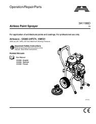
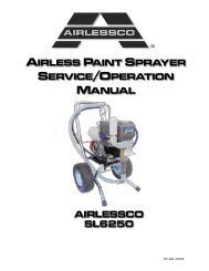
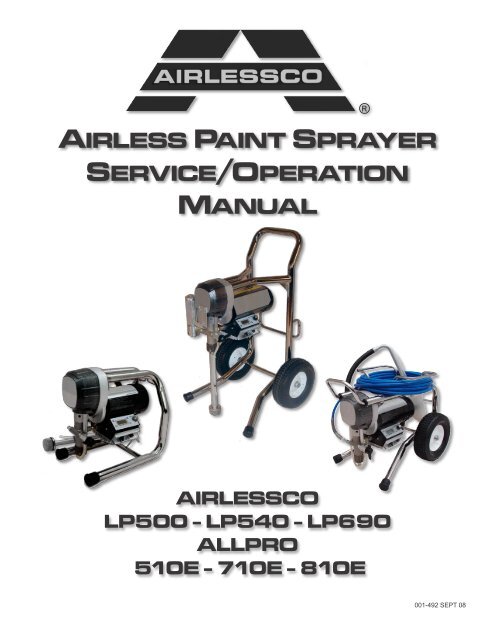
AIRLESS PAINT SPRAYERSERVICE/OPERATIONMANUAL®AIRLESSCOLP500 - LP540 - LP690ALLPRO510E - 710E - 810E001-492 SEPT 08
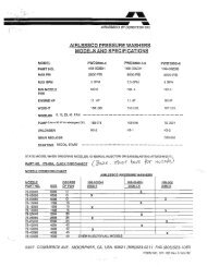
INTRODUCTIONCARRY FRAMEHI-BOY FRAMEYour new <strong>Airlessco</strong> or ALLPRO <strong>airless</strong> <strong>paint</strong> <strong>sprayer</strong>is designed to meet the demands of the professional<strong>paint</strong>ing contractor as well as the homeowner. The famous<strong>Airlessco</strong> slow-stroking stainless steel piston pump deliversextra long life for the piston, packings, valve seats andballs. The patented Triple-Life packing system is externallyadjustable, extending packing life and reducing repackingcosts. Its large high-torque electric motor runs slowerreducing heat. The motor is fan cooled and totally enclosedto reduce brush wear and to prevent the ignition of <strong>paint</strong>fumes in the motor.LO-BOY FRAMELP500510ELP540710ELP690810EMax Pressure 3000 PSI 3000 PSI 3000 PSIOutput (FreeFlow) 0.60 GPM 0.75 GPM 0.85 GPMOutput (At Pressure) 0.50 GPM 0.57 GPM 0.62 GPMTip Size (1 Gun) 0.023 in. 0.027 in. 0.029 in.Motor DC TEFC0.6 HPDC TEFC0.9 HPDC TEFC0.9 HPWARNINGHANDLE THIS UNIT AS YOU WOULD A LOADED FIREARM!HIGH PRESSURE SPRAY CAN CAUSE EXTREMELYSERIOUS INJURY. OBSERVE ALL WARNINGS!MANUAL NOTATIONSWARNING - Alerts user to avoid or correct conditions thatcould cause bodily injury.CAUTION - Alerts user to avoid or correct conditions thatcould cause damage to or destruction of equipment.IMPORTANT - Alerts users to steps or procedures that areessential to proper equipment repair and maintenance.NOTE - Identifies essential procedures or extra information.BEFORE OPERATING THIS UNIT, READ AND FOLLOWALL SAFETY WARNINGS AND INSTRUCTIONS RELATEDTO THE USAGE OF THIS EQUIPMENT ON PAGES 2, 3 & 4.READ, LEARN, AND FOLLOW THE PRESSURE RELIEFPROCEDURE ON PAGE 8 OF THIS MANUAL.All Service Procedures to be performed by an Authorized <strong>Airlessco</strong> Service Center ONLY.NO MODIFICATIONS or alterations of any AIRLESSCO Equipment or part is allowed.1
WARNINGS - CONTINUEDAVOID COMPONENT RUPTUREThis <strong>sprayer</strong> operates at 3000 psi (205 bar). ALWAYS besure that all components and accessories have a maximumworking pressure of at least 3000 psi to avoid rupturewhich can result in serious bodily injury including injectionand property damage.NEVER leave a pressurized <strong>sprayer</strong> unattended to avoidaccidental <strong>operation</strong> of it which could result in seriousbodily injury.ALWAYS follow the PRESSURE RELIEF PROCEDUREwhenever you stop spraying and before adjusting,removing or repairing any part of the <strong>sprayer</strong>.NEVER alter or modify any part of the equipment to avoidpossible component rupture which could result in seriousbodily injury and property damage.NEVER use weak or damaged or non-conductive <strong>paint</strong>hose. Do not allow kinking or crushing of hoses or allow itto vibrate against rough or sharp or hot surfaces. Beforeeach use, check hoses for damage and wear and ensureall fluid connections are secure.REPLACE any damaged hose. NEVER use tape or anydevice to mend the hose.NEVER attempt to stop any leakage in the line or fittingswith your hand or any part of the body. Turn off the unitand release pressure by following PRESSURE RELIEFPROCEDURE.ALWAYS use approved high pressure fittings andreplacement parts.ALWAYS ensure fire extinquishing equipment is readilyavailable and properly maintained.WARNING: Do not use halogenated solvents in this system.The prime valve, 2 gun manifold and most <strong>airless</strong> guns havealuminum parts and may explode. Cleaning agents, coatings,<strong>paint</strong>s or adhesives may contain halogenated hydrocarbonsolvents. DON"T TAKE CHANCES! Consult your materialsuppliers to be sure. Some of the most common of thesesolvents are: Carbontetrachloride, Chlorobenzene, Dichloroethane,Dichloroethyl Ether, Ethylbromide, Ethylchloride,Tethrachloethane. Alternate valves and guns are available ifyou need to use these solvents.PREVENT STATIC SPARKED FIRE/ EXPLOSIONSALWAYS be sure all equipment and objects being sprayedare properly grounded.ALWAYS ground <strong>sprayer</strong>, <strong>paint</strong> bucket and object beingsprayed. See "grounding" on page 3 for detailed groundinginformation. Vapors created when spraying can be ignitedby sparks. To reduce the risk of fire, always locate the<strong>sprayer</strong> at least 20 feet (6 m.) away from the spray area.DO NOT plug in or unplug any electrical cords in the sprayarea, which can create sparks, when there is any chance ofigniting vapors still in the air. Follow the coating & solventmanufacturers safety warnings and precautions.Use only conductive fluid hoses for <strong>airless</strong> applications. Besure gun is grounded through hose connections. Checkground continuity in hose & equipment. Overall (end toend) resistance of unpressurized hose must not exceed 29megohms for any coupled length or combination of hoselength. Use only high pressure <strong>airless</strong> hoses with staticwire approved for 3000 psi.FLUSHINGReduce the risk of injection injury, static sparking orsplashing by following the specific cleaning procedure onpage 5.ALWAYS follow the PRESSURE RELIEF PROCEDUREon page 8.ALWAYS remove the spray tip before flushing. Hold ametal part of the gun firmly to the side of a metal pail anduse the lowest possible fluid pressure during flushing.NEVER use cleaning solvents with flash points below 140degress F. Some of these are: acetone, benzene, ether,gasoline, naphtha. Consult your supplier to be sure.NEVER SMOKE IN THE SPRAYING/CLEANING AREA.IMPORTANT: United States Government safety standardshave been adopted under the Occupational Safety & HealthAct. These standards, particularly the General Standards,Part 1910, & the Construction Standards, part 1926 shouldbe consulted.WHEN SPRAYING & CLEANING WITH FLAMMABLE PAINTS OR THINNERS:41. When spraying with flammable liquids, the unit must be located a minimum of 25 feet away from the spraying area ina well ventilated area. Ventilation must be sufficient enough to prevent the accumulation of vapors.2. To eliminate electrostatic discharge, ground the spray unit, <strong>paint</strong> bucket and spraying object. Use only highpressure <strong>airless</strong> hoses approved for 3000 psi which is conductive.3. Remove spray tip before cleaning gun and hose. Make contact of gun with bucket and spray without the tip in a wellventilated area, into the grounded steel bucket.4. Never use high pressure in the cleaning process. USE MINIMUM PRESSURE.5. Do not smoke in spraying/cleaning area.
FLUSHING1. NEW SPRAYER 5. STORAGEYour unit was factory tested in an oil solution which was leftin the pump. Before using oil-base <strong>paint</strong>, flush with mineralspirits only.Before using water-base <strong>paint</strong> flush with mineral spirits,followed by soapy water, then a clean water flush.2. CHANGING COLORSFlush with a compatible solvent such as mineral spirits orwater.3. CHANGING FROM WATER-BASE TOOIL-BASE PAINTFlush with soapy water, then mineral spirits.4. CHANGING FROM OIL-BASE TOWATER-BASE PAINTFlush with mineral spirits, followed by soapy water, then aclean water flush.HOW TO FLUSHFIG. 1 FIG. 2REMOVE SPRAY TIPPRESSURE CONTROL KNOBOil-base <strong>paint</strong>: Flush with mineral spirits.Water-base <strong>paint</strong>: Flush with water, then mineral spirits andleave the pump, hose and gun filled with mineral spirits.For longer storage, use mixture of mineral spirits and motoroil (half & half). Shut off the <strong>sprayer</strong>, follow PRESSURERELIEF PROCEDURE on page 8 to relieve pressure andmake sure prime valve is left open.6. START UP AFTER STORAGEBefore using water-base <strong>paint</strong>, flush with soapy water andthen a clean water flush.When using oil-base <strong>paint</strong>, flush out the mineral spirits withthe material to be sprayed.FIG. 3 FIG. 4CLOSED(Pressure)PRIME VALVEOPEN(Priming & Pressure ReliefMAINTAIN FIRM METAL TO METAL CONTACTBETWEEN GUN AND CONTAINERHIGH PRESSUREFlushing Procedure1. Be sure the gun safety latch is engaged and there isno spray tip in the gun. Refer to Fig. 1. Refer to yourseparate instruction <strong>manual</strong> provided with your gun on itssafety features and how to engage safety latch.2. Pour enough clean, compatible solvent into a large,empty metal pail to fill the pump and hoses.3. Place the suction tube into the pail or place the pailunder the pump.4. Turn pressure control knob to low. Refer to Fig. 2.5. Open the prime valve to the open - "Priming Position".This will allow an easy start. Refer to Fig. 3.6. Turn the engine ON/OFF switch to ON.7. Point the gun into the metal pail and hold a metal part ofthe gun firmly against the pail Refer to fig.4.8. Disengage the gun safety latch and squeeze the trigger.At the same time, slowly turn the pressure control knobclockwise just enough to move liquid at low pressure.9. Allow the pump to operate until clean solvent comesfrom the gun.WARNING: To reduce the risk of static sparking, whichcan cause fire or explosion, always hold a metal part ofthe gun firmly against the metal pail when flushing. Thisalso reduces splashing. Refer to Fig 4.10. Release the trigger and engage the gun safety latch.11. If you are going to start spraying, place the pump orsuction tube into the supply container. Release thegun safety latch and trigger the gun into another empty,metal container, holding a metal part of the gun firmlyagainst the metal pail (Fig. 4), forcing the solvent fromthe pump and hose. When <strong>paint</strong> starts coming from gun,turn pressure control knob to minimum pressure, placeprime valve in prime (open) position and engage the gunsafety latch.12. If you are going to store the <strong>sprayer</strong>, remove the suctiontube or pump from the solvent pail force the solvent fromthe pump and hose. Engage the gun safety latch andrefer to the "Storage" Procedure above. Step 5.13. Whenever you shut off the <strong>sprayer</strong> follow PRESSURERELIEF PROCEDURE warning on page 8.5
SETTING UP1. CONNECT THE HOSE AND GUNa. Remove the plastic cap plug from the outlet and screw aconductive or grounded 3000 psi spray hose ontofluid outlet.b. Connect an <strong>airless</strong> spray gun to the other end of thehose, but do not install the spray tip yet!NOTE: Do not use thread sealer on swivel unions as theyare made to self seal.2. FILL THE PACKING NUT/WET CUPFIG. 5Fill the Packing Nut/WetCup with 5 drops of<strong>Airlessco</strong> Throat SealOil (TSO).3. ELECTRICAL SERVICEBe sure the electrical <strong>service</strong> is 120 VAC, 15 ampminimum, and that the outlet you use is properly grounded.NOTE: FOR GENERATOR POWER, A MINIMUMOF 7000 WATT GENERATOR WITH VOLTAGEREGULATION MUST BE USED.4. GROUNDINGWARNING: To reduce the risk of static sparking, fire or explosionwhich can result in serious bodily injury and propertydamage, always ground the <strong>sprayer</strong> and system componentsand the object being sprayed, as instructed in the safety warningsection of this <strong>manual</strong>.5. FLUSH THE SPRAYERFollow “Flushing Procedure” on page 5 of this <strong>manual</strong>.STARTING UP1. LEARN THE FUNCTIONS OF THECONTROLS.PRIME/PRESSURE (PR) RELIEF VALVE is used toprime pump and to relieve pressure from gun, hose and tip.Prime/Pressure Relief ValvePRESSURE CONTROL KNOB is used toadjust pressure. Turn clockwise (CW) toincrease pressure and counterclockwise(CCW) to decrease pressure.FIG. 6PRIME/PRESSURE RELIEFVALVE (PRIME/PR VALVE):Used to relieve pressure fromgun/hose/tip and to primethe unitwhen in OPEN position. (It is inopen position when there is awider gap between valve handleand cam body). Learn and followthe PRESSURE RELIEF PROCE-DURE on page 8 of this <strong>manual</strong>.When in closed position (veryslight gap) the system is pressurizedand ready to spray.(Prime/PR Valve) Used to relieve pressurefrom gun, hose & tip and to primethe unitwhen in OPEN position. (It is in open positionwhen there is a wider gap between valvehandle and cam body.)When in CLOSED position,there is only avery slight gapbetween handle & body. Whenclosed the system ispressurized. Handle as aloaded firearm!PRESSURE CONTROL KNOB:used to adjust pressure only.Turn clockwise to increasepressure and counterclockwiseto decrease pressure.6When you turn the valve handle and the gap between the valve handle and the cam bodybecomes wider - this means the valve is in the open position. It is in the closed positionwhen the gap becomes very small.ON/OFF SWITCHFUSE
STARTING UP2. PREPARE THE MATERIALa. Prepare the material according to the materialmanufacturer's recommendations.b. Place the suction tube into the material container.3. STARTING THE SPRAYERa. Prime/PR Valve must be "OPEN" in the primingposition.b. When you have ensured that the gun safety latch isengaged, attach tip and safety guard.c. Turn the engine ON/OFF switch to the "ON"position.d. Turn Pressure Control Knob clockwise to prime thepump.e. After the pump is primed, turn Prime/PR Valve to the"Closed" position.f. Turn Pressure Control Knob to the desired spraypressure.g. Disengage the gun safety latch and you are ready tospray.4. ADJUSTING THE PRESSUREa. Turn the Pressure Control Knob Clockwise to increasepressure and counterclockwise to decrease pressure.b. Always use the lowest pressure necessary to completelyatomize the material.NOTE: OPERATING THE SPRAYER AT HIGHERPRESSURE THAN NEEDED, WASTES MATERIAL,CAUSES EARLY TIP WEAR, AND SHORTENSSPRAYER LIFE.c. If more coverage is needed, use a larger tip rather thanincreasing the pressure.WARNINGTo stop the unit in an emergency, turn the engine off. Thenrelieve the fluid pressure in the pump and hose as instructedin the PRESSURE RELIEF PROCEDURE.5. WHEN SHUTTING OFF THE SPRAYERa. Whenever you stop spraying, even for a short break,follow the PRESSURE RELIEF PROCEDURE.b. Clean the tip & gun as recommended in the seperateGun Manual supplied with the gun.c. Flush the <strong>sprayer</strong> at the end of each work day, if thematerial you are spraying is water-based, or if it couldharden in the <strong>sprayer</strong> overnight. See "Flushing". Use acompatible solvent to flush, then fill the pump and hoseswith an oil based solvent such as mineral spirits.d. For long term shutdown or storage, refer to the"Flushing" section of this <strong>manual</strong>.WARNINGBe sure to relieve pressure in the pump after filling with<strong>Airlessco</strong> Pump Conditioner.AVOIDING TIP CLOGSThere is an easy way to keep the outside of the tip clean frommaterial build up:Every time you stop spraying, for even a minute, lock the gunand submerge it into a small bucket of thinner suitable for thematerial sprayed.Thinner will dissolve the buildup of <strong>paint</strong> on the outside of tip,tip guard and gun much more effectively if the <strong>paint</strong> doesn'thave time to dry out completely.d. Check the spray pattern. The tip size and angledetermines the pattern width and flow rate.WARNINGFOLLOW THE "PRESSURE RELIEF PROCEDURE".To reduce the risk of injection, never hold your hand, body,fingers or hand in a rag in front of the spray tip when cleaningor checking for a cleared tip. Always point the gun toward theground or into a waste container when checking to see if thetip is cleared or when using a self-cleaning tip.WARNINGWhen you spray into the <strong>paint</strong> bucket, always use thelowest spray pressure and maintain firm metal to metal contactbetween gun and container.7
PRESSURE RELIEF PROCEDURE!IMPORTANT!TO AVOID POSSIBLE SERIOUS BODY INJURY, ALWAYS FOLLOW THIS PROCEDURE WHENEVER THESPRAYER IS SHUT OFF, WHEN CHECKING IT, WHEN INSTALLING, CHANGING OR CLEANING TIPS,WHENEVER YOU STOP SPRAYING, OR WHEN YOU ARE INSTRUCTED TO RELIEVE THE PRESSURE.1. Engage the gun safety latch. Refer to the separateinstruction <strong>manual</strong> provided with your gun on its safetyfeatures and how to engage safety latch.2. Turn the unit off.3. Disengage the gun safety latch and trigger the gun torelieve residual fluid pressure.HOLD METAL PART OF THE GUN IN CONTACT WITHGROUNDED METAL PAIL. USE MINIMUM PRESSURE !4. Turn Prime/Pressure Relief Valve (PRValve) to the open (priming) position torelieve residual fluid pressure.THERE WILL BE A WIDER GAP BETWEEN VALVEHANDLE AND CAM BODY WHEN IN OPEN POSITION.IN THE CLOSED POSITION THERE IS ONLY A VERYSLIGHT GAP.NOTE: THE VALVE HANDLE CAN MOVE BOTHCLOCKWISE AND COUNTER CLOCKWISE AND CANFACE DIFFERENT DIRECTIONS.5. Re-engage gun safety latch and closePrime/Pressure Relief Valve.DAILY MAINTENANCEIf the SPRAY TIP OR HOSE IS CLOGGED, follow Step1 through 5 above. Expect <strong>paint</strong> splashing into the bucketwhile relieving pressure during Step 4.If you suspect that pressure hasn't been relieved due todamaged Prime/Pressure Relief Valve or other reason,engage the gun safety latch and take your unit to anauthorized <strong>Airlessco</strong> Service Center.1. Keep the displacement pump packing nut/wet cup lubricated with <strong>Airlessco</strong> TSO (Throat Seal Oil) at all times. TheTSO helps protect the rod and the packings.2. Inspect the packing nut daily. Your pump has a patented Triple Life Packing System. Packing life will be extended aminimum of three times if the following "Packing Adjustment" procedure is followed:IF SEEPAGE OF PAINT INTO THE PACKING NUT AND/OR MOVEMENT OF THE PISTON UPWARD IS FOUND(WHILE NOT SPRAYING), THE PACKING NUT SHOULD BE TIGHTENED ENOUGH TO STOP LEAKAGE ONLY,BUT NOT ANY TIGHTER. OVERTIGHTENING WILL DAMAGE THE PACKINGS AND REDUCE THE PACKING LIFE.8
AIRLESS SPRAY GUN OPERATIONSPRAYAttach spray gun to <strong>airless</strong> unit and tighten fittings securely.Set the gun safety latch. (Also may be called gun safetylock, or trigger lock)FIG. 7GUN SAFETY LATCHIN LOCKED POSITIONGUN SAFETYLATCH* The gun safety latch should always be set when the gunis not being triggered.Read all warnings and safety precautions supplied with thespray gun and in product <strong>manual</strong>.MAJOR COMPONENTS OF SPRAY GUN AND REVERSIBLE SPRAY TIPFIG. 8 FIG. 9O-RING GASKETREVERSIBLESPRAY TIPTIP GUARDGUN SAFETYLATCH OR LOCKHANDLE(FILTER INSIDE)METAL SEATRELEASEDREV-TIPREV-GUARDTRIGGER GUARDSPRAY TIP ASSEMBLY1. Be sure PRESSURE RELIEF PROCEDURE is followedbefore assembling tip and housing to the gun.2. Lock gun safety latch.3. Insert REV-TIP cylinder into theREV-GUARD (guard housing assembly).4. Guide metal seat into REV-GUARD (guardhousing assembly) through retaining nut & turn until itseats against the cylinder.5. Insert O-Ring gasket on metal seat so it fits in thegrooves.6. Finger tighten REV-GUARD retaining nut on gun.7. Turn guard in the desired position.8. Completely tighten the retaining nut.FIG. 10RETAINING NUTREV-GUARDGUARD HOUSING ASSEMBLYG Thread 7/8" 561-002F Thread 11/16" 561-001REV-TIP CYLINDERPart # 561-XXXO-RING GASKETPart # 561-026METAL SEATPart # 561-029CLEANING SPRAY GUNImmediately after the work is finished, flush the gun outwith a solvent. Brush pins with solvent and oil them lightlyso they will not collect dried <strong>paint</strong>.CLEANING FILTER IN GUN HANDLETo clean the filter, use a brush dipped in an appropriatesolvent. Change or clean filters at least once a day. Sometypes of latex may require a filter change after four hours of<strong>operation</strong>.TO REMOVE CLOGS FROM SPRAY TIP1. Lock gun safety latch.2. Turn REV-TIP handle 180 degrees.3. Disengage trigger lock & trigger gun into pail.4. If the REV-TIP handle appears locked (resiststurning), loosen the retaining nut. The handle will nowturn easily.5. Engage gun safety latch & return handle to thespray position.RETAINING NUTCLOGGED FLAT TIPREVERSE TOUNPLUGSpray Position ShownShould the spray tip become clogged, relieve pressurefrom hose by following the PRESSURE RELIEFPROCEDURE. Secure gun with the safety latch, takeoff guard, take out the tip, soak in appropriate solvent &clean with a brush. (Do not use a needle or sharp pointedinstrument to clean the tip. The tungsten carbide is brittleand can chip.)9
AIRLESS SPRAY GUNFIG. 11678910*54111*2*3*1213141516PARTS LIST FIGURE 11Item No. Part No. Description201 120-530 Gun Seat Assembly2 120-535 Gasket-Seat19173 120-520 Needle Assembly4 120-529 Gun Seat Adapter5 120-562 Trigger Guard186 120-539119-055119-054Pivot Trigger Pin (008 Gun)Bolt (Prolight Gun)Nut (Prolight Gun)7 120-509120-109Gun Head (008 Gun)Gun Head (Prolight Gun)8 120-540 Actuator Pin (2)9 120-536 Gun Plate10* 120-038 Nut11 120-056 Plastic Washer12 120-538 Gun Trigger Lock13 120-055 Wave Washer14 120-049 Retaining Ring15 120-082 Handle Seal16 120-090CX Gun Filter-Coarse120-090FXGun Filter-Fine17 120-088 Spring18 120-099120-106Gun Handle Assy (008 Gun)Gun Handle Assy (Prolight Gun)19 120-506 Gun Trigger (008 Gun)20 120-542 Gun Trigger (Prolight Gun)* 120-534 Gun Repair Kit10
AIRLESS SPRAY GUN TROUBLESHOOTINGDEFECTS CAUSE CORRECTIONCoarse spray Low pressure Increase the pressureExcessive fogging(overspray)High pressureMaterial too thinPatten too wide Spray angle too large Use smaller spray angle tipReduce the pressure to satisfactory pattern distrabutionUse less thinnerPattern too narrow Spray angle too small Use larger spray angle tip (if coverage is OK, try tip in samenozzle group)too much material Nozzle too largeMaterial too thinPressure too highUse smaller nozzleReduce pressuretoo little material Nozzle too small Use next larger nozzleMaterial too thickthin distribution in centerof pattern “horns”Thick skin of workCoating fails to close &smooth overSpray pattern irregular,deflectedCraters or pock marks,bubbles on workClogged screensExcess <strong>paint</strong> builds ontip guardDrips, spits from tipTip clogs continuallyWorn tipWrong tipMaterial too viscousApplication too heavyMaterial too viscousOrifice cloggedTip damagedSolvent balanceExtraneous material in <strong>paint</strong>Course pigmentsPoorly milled pigments(<strong>paint</strong> pigments glocculate)Spray gun too close tosurfacePressure setting too highValve seat and/or ball in gunhead damaged or wornDebris in <strong>paint</strong>Gun filter missingCoarse filter meshChange to new tipUse nozzle with narrow spray angleThin cautiouslyReduce pressure and/or use tip in next smaller nozzle groupThin cautiouslyClean carefullyReplace with new tipUse 1 to 3% “short solvents remainder “long” solvents(this is most likely to happen with material of low viscosity,lacquers, etc.)Clean screenUse coarse screen if orifice size allows.Use courser screen, larger orifice tips. Obtain ball milled<strong>paint</strong>. If thinner has been added, test to see if a coverscreen. Incompatible drop placed on top of <strong>paint</strong> mixes orflattens out on the <strong>paint</strong> mixture & thinners on the surface. Ifnot, try different thinner in fresh batch of <strong>paint</strong>.Hold gun further from surface sprayedReduce pressure settingService spray gun, replace valve assemblyThouroughly strain the <strong>paint</strong> before useDo not operate without inlet strainerTEST THE PATTERNGOOD, FULLSPOTTY PATTERN, INCREASE PRESSURE11
FIELD TROUBLESHOOTINGPROBLEM CAUSE SOLUTIONUnit doesn’t primeUnit primes but has pooror no pressureUnit does not maintaingood spraying pressureUnit does not run.Airleak due to:•Loose suction nut• Worn o-rings• Hole in suction hoseStuck or fouled ballsPressure set too lowFilter(s) are cloggedOutlet valve fouled/wornPrime/pressure relief valvebypassingPackings and/or piston wornBlown spray tipPackings and/or pistons wornUpper seat wornBlown FuseElectrical Faliure• tighten suction nut• replace o-ring (106-018) on suction seat & o-ring (106-017)below suction seat• replace suction hose• <strong>service</strong> inlet and outlet valves• turn up pressure• clean or replace gun filter, inlet filter, and/or manifold filter• <strong>service</strong> outlet valve• clean or replace prime valve (100-180)• tighten packing nut• repack unit• replace spray tip• repack unit• replace upper seat• replace fuse20A Slow Blow (331-328)• see electrical troubleshootingMANIFOLD FILTER (111-200-99)FIG. 1312345678910PARTS LIST FIGURE 13Item No. Part No. Description1 111-202 Base2 301-356 Spring3 106-007 O-Ring4 111-204 Filter 60 Mesh5 111-203 Support6 111-201 Base7 100159 Swivel8 100-129 Plug 3/8” (2)9 100-109 Nipple 3/8”M x 1/4”M10 100-028 Plug 1/4”14
PACKING REPLACEMENT PROCEDURESDISASSEMBLY OF THE FLUID PUMPREFER TO FIGURE 17 & 181. Disconect the Fluid Pump as instructed on page 15.2. Unscrew & remove the packing nut.3. Push the piston rod down through the packings & out ofthe pump.4. Now push the packing removal tool up throughthe pump& remove from the top bringing packings, spacer &springs along with it, leaving fluid body empty.*Make sure all old packings & glands have beenremoved from fluid pump.5. Clean inside of fluid body.6. Disassemble all parts & clean for reassembly. Discardany old packings.7. Lubricate leather packing in lightweight oil for 10 minutesprior to reassembly.REASSEMBLYREFER TO FIGURE 171. Take lower male gland & place it down on theflat side.2. Take three of the lower polyethylene packings & two ofthe leather packings & place onto the male gland inthefollowing order with the inverted side downPOLYETHYLENE, LEATHER, POLYETHYLENE,LEATHER, POLYETHYLENE.3. Take the female adaptor, which is inverted on both sides, & place it on top of your assembled lower packings.4. Follow step 2 with your packings inverted side up.5. Take the second lower male gland and place it on topof your assembled packings with the rounded sidedown.6. Take assembled glands & packings (13 pieces) & slideonto the lower half of the piston.7. Take the spacer & slide over the top of the piston(itdoesn’t matter which direction it sits, falling onto lowerpackings.8. Take three Belleville Springs & slide over the top of thepiston in the following order:• First spring, curve facing down• Second spring, curve facing up• Third spring, curve facing down9. Take the upper male gland & place it roundedside up.10. Take three upper polyethylene packings & two leatherpackings & assemble with inverted side down, onto the male gland in the following order: polyethylene,leather, polyethylene, leather, polyethylene.11. Take upper female gland & place on top of assembledupper packings with the inverted side down.12. Take assembled upper glands & packings (7 pieces) &slide on over the top of the piston, making sure invertedsides are down.( ((13. Take the packing holder & replace the white O-ring &the black O-ring with new ones from the packing kit.14. Slide the packing holder over the top of the upperpackings so they fit inside.15. Lubricate inside of the fluid pump body & the outside ofthe packings with a light weight oil.16. Slide assembly into fluid pump body.TO KEEP PACKINGS SECURED IN CORRECTPOSITION, HOLD THE PUMP BODY UPSIDE DOWN& PUSH THE COMPLETED ASSEMBLY UPWARDSINTO THE PUMP BODY. ONCE PLACED INSIDE, TILTPUMP BODY BACK UP TO KEEP ALL PIECES IN.17. Tighten packing nut onto the top of the fluid pumpbody & tighten until you feel slight resistance against theBelleville Springs. Using the Packing Adjustment Tool,tighten another 3/4 of a turn.!8. Reinstall Fluid Pump as instructed on page 15.FIG. 17212019181716151413111210PARTS LIST ON FOLLOWING PAGE252422231232145678917
PACKING REPLACEMENT PROCEDURESFIG. 1819*201418*25*2124*22*417*16*1*15*13*2*113*12*523*1*7*6*PARTS LIST FIGURE 17 & 18Item No. Part No. Description1* 331-014 Male Gland2* 331-016 Packing Polyethylene3* 331-308 Female Adaptor4 331-011 Fluid Pump Body5 331-029 Suction Ball Guide6* 331-030 Suction Ball7* 106-011 O-Ring8 331-409331-292Suction Seat (Carry & Lo-Boy)Suction Seat (Hi-Boy)9 331-034 Suction Nut10 331-314 Outlet Seat Retainer11 331-026 Outlet Seat12* 331-100 O-Ring13* 331-027 Outlet BallPARTS LIST FIGURE 17 & 18 CONT.Item No. Part No. Description14 331-708 Piston15* 331-018 Spacer16* 331-025 Belleville Springs17* 331-022 Male Gland18* 331-023 Packing Polyethylene19* 331-021 Female Gland20 331-019 Packing Holder21 331-037 Packing Nut22* 331-307 Packing Leather23* 331-306 Packing Leather24* 106-009 White O-Ring25* 106-010 Black O-Ring* 331-210 Packing Kit18
GEAR AND PUMP ASSEMBLYFIG 19121213SERVICING GEAR BOX ASSEMBLY1. Remove fluid pump as per "Fluid Pump Disconnect"procedures on page 15.2. Remove frame from the gearbox by loosening the fourmounting screws.3. Refer to Figure 19. Separate cover assembly from boxby removing bolts from front of cover & back of box &shoulder bolts from front of cover & back of box.4. Lay unit on its back and disassemble gearbox.5. Inspect bearings, Crosshead Assembly, Gearcrank &sleeve bearing inside cover assembly for wear/damage.Replace worn/damaged parts.6. If gear grease needs replacing, replace with gear grease(Part No. 331-132).7. Clean mating surfaces of cover and box thoroughly.Use Part No. 105-331 BLUE XS ADVANCED RTVSILICONE INSTANT GASKET.8. Reassemble in reverse order.GEARBOX SLEEVE BEARINGREPLACEMENTFIG 201231014 15 16 1711987456123MOTORPARTS LIST FIGURE 19Item No. Part No. Description1 100-381 Bolt (2)2 100-380 Shoulder Bolt (2)3 331-088 Retaining Ring4 331-117 Sleeve5 331-062 Retaining Spring6 331-209331-236Pump Assy (Carry and Lo-Boy)Pump Assy (Hi-Boy)7 115-019 Hose Connector (1/4NPSXNPT)8 119-028 Pin9 331-061 Sleeve Bearing10 100-318 Bolt (2)11 331-074 Tube Spacer12 331-111 Shield13 331-234 Cover14 331-046 Bearing15 331-038 Crosshead Assy16 331-406331-407331-593331-59017 331-047 BearingWARNINGDO NOT OPERATEWITHOUT COVERGUARD IN PLACEGear Crank (510E)Gear Crank (LP 500)Gear Crank (LP 540/710E)Gear Crank (LP 690/810E)*NOTE: Can be ordered separately, but is included withMotor Ass'y.PARTS LIST FIGURE 20Item No. Part No. Description1 331-061 Sleeve Bearing2 331-103 Washer (2)3 331-197 Screw (2)NOTE: WHEN REPLACING ITEM (1), COVER OUTSIDEOF SLEEVE WITH CLEAR SILICONE PRIOR TOINSERTING INTO COVER ASSEMBLY19
CARRY FRAME MODELSFIG. 2119 201, 2, 3181741615145671312111098PARTS LIST FIGURE 21Item No. Part No. Description1 331-785 Fan2 331-786 Fan Cover3 117-090 Fan Cover Screws (3)4 117-044 Knob5 331-321 Terminal Box6 331-787 Bolt (.6HP)7 111-037 Heatsink Screw (4)8 100-382 Screw (2)9 106-500 Sensor Seal10 331-294-99 SensorPARTS LIST FIGURE 21 CONTItem No. Part No. Description11 100-003 Swivel12 100-180 Prime Valve13 331-048 Rubber Boot (2)14 100-318 Bolt (2)15 115-019 Hose Connector (1/4”)16 331-074 Tube Spacer (2)17 331-111 Shield18 331-234 Cover19 331-401 Frame20 119-048 Screw (4)20
LO-BOY MODELSFIG. 2228 29 30 31 32 3326 27251, 2, 3456724232282120191817161514131211109PARTS LIST FIGURE 22Item No. Part No. Description1 331-785 Fan2 331-786 Fan Cover3 117-090 Fan Cover Screws (3)4 117-129 Screw (2)5 119-033 Nut (2)6 331-477 Cup Support7 331-476 Cup Assembly8 143-029 Collar (2)9 113-019 10” Wheel (2)10 305-039 Spacer (2)11 331-337 Rubber Edge (2) (690)12 117-044 Knob13 111-037 Heatsink Screws (4)14 331-321 Terminal Box15 331-048 Rubber Boot (2)16 106-500 Sensor Seal17 331-294-99 SensorPARTS LIST FIGURE 22 CONTItem No. Part No. Description18 100-003 Swivel19 100-180 Prime Valve20 100-318 Bolts (2)21 115-019 Hose Connector (1/4”)22 331-074 Tube Spacer (2)23 331-111 Shield24 331-234 Cover25 331-174 Handle26 119-032 Screw (2)27 331-176 Bushing (2)28 331-365 Frame Assy39 119-048 Screw (4)30 331-788 Bolt (.9HP)31 331-222 Pin (2)32 331-175 Spacer (2)33 331-795 Motor Cover21
HI-BOY MODELSFIG. 2324, 25, 2620 21 22 2319181234517161511614121379810PARTS LIST FIGURE 23Item No. Part No. Description1 331-795 Motor Cover2 331-788 Bolt (.9HP)3 331-337 Rubber Edge (690)4 117-044 Knob5 331-321 Terminal Box6 111-037 Heatsink Screws7 143-029 Collar (2)8 113-019 10” Wheel (2)9 113-030 Spacer (2)10 331-048 Rubber Boot11 106-500 Sensor Seal12 331-294-99 Sensor13 100-003 SwivelPARTS LIST FIGURE 23 CONTItem No. Part No. Description14 100-180 Prime Valve15 331-074 Tube Spacer (2)16 100-318 Bolt (2)17 115-019 Hose Connector (1/4”)18 331-111 Shield19 331-336 Pail Hook20 331-234 Cover21 100-373 Screw (2)22 331-273 Frame23 119-048 Screw (4)24 331-785 Fan25 331-786 Fan Cover26 331-090 Fan Cover Screw22
SUCTION ASSEMBLIESLO-BOY AND CARRY CHASSIS (331-238) HI-BOY CHASSIS (331-284)FIG. 24FIG. 25179231015456428367PARTS LIST FIGURE 24Item No. Part No. Description1 331-290 Suction Hose Assy2 331-217 Inlet Strainer3 331-035 Suction Elbow4 331-034 Suction Nut5 106-020 PTFE O-Ring6 331-231 Bypass Hose Assy7 331-425 Bypass Hose8 331-090R Fitting9 111-016 Nylon Tie10 331-135 Spring ClipPARTS LIST FIGURE 25Item No. Part No. Description1 331-090R Fitting2 331-034 Suction Nut3 331-292 Suction Seat Assy4 301-348 Bypass Hose Assy5 116-103 Spring Clip6 331-400 Inlet Tube7 141-008 Inlet Strainer23
PRESSURE CONTOL ASS'Y CALIBRATION24NOTE: ANYTIME A SENSOR OR PRESSURE CONTROL ASSEMBLY (BOARD) OR BOTH ARE REPLACED, THEFOLLOWING CALIBRATIONS MUST BE PERFORMED.NOTE: PRESSURE CONTROL ASSEMBLIES (BOARDS) ARE NOW BEING EQUIPPED WITH A GREENGROUNDING WIRE ATTACHED. CONTECT THE GROUNDING WIRE TO TERMINAL BOX USING THE SAMESCREW THAT HOLDS THE GROUNDING WIRE FROM THE POWER CORD.1. ZERO CALIBRATION1. Place prime/pressure relief valve in the prime (open)position.2. Set the pressure control knob to the minimum setting(CCW).3. Remove the screws and lower the pressure controlassembly.4. Remove any jumper on the "P-ZR" terminal. Note: ThisJumper is no longer used.5. Turn machine "ON" and ensure it is not cycling.6. If the yellow light on the electrical board is ON and youhave "0000" on the LCD display, the Zero Calibrationis complete no further adjustment is necessary. If thelight is ON and there are numbers on the display, usean insulated screwdriver to turn the "ZERO" trimpotcounter-clockwise until the light goes out. Then turnit clockwise until the yellow light comes on, continueto turn the trimpot and the numbers will reduce untillthe LCD shows "0000." The Zero Calibration is nowcomplete. If you adjust beyond "0000" the numbers willstart to increase.If the digital display shows "- - -" and no yellow light, youshould turn the Zero trimpot clockwise until theyellow light is on, continue turning until "0000" is shown.The goal is to see "0000" on the digital display, this iswhen you have Zero Calibration (Relying on theyellow light is no longer used.)2. PRESSURE CALIBRATION1. Complete the ZERO calibration, as per "ZEROCALIBRATION" prior to commencing this calibration.2. Attach a 50', 1/4" <strong>airless</strong> hose, <strong>airless</strong> gun with 0.017 tipand a 5000 psi glycerin filled pressure gauge to pump.3. Place the suction tube into a bucket of Coro-chek andwater.4. Turn prime/pressure relief valve to the prime (open)position.5. Turn pressure control knob clockwise until machinestarts to prime.6. Place the prime/pressure relief valve in the pressure(closed) position.7. While watching pressure gauge, slowly adjust thepressure trimpot (clockwise to increase and counterclockwise to decrease) until the maximum staticpressure is 3000 psi, with the pressure control knobfully clockwise. Trigger the gun several times to ensurepressure returns to 3000 psi .3. LCD DISPLAY CALIBRATIONIF SO EQUIPED1. Complete the "ZERO CALIBRATION" and "PRESSURECALIBRATION" procedures prior to commencing thiscalibration.2. Turn pressure control knob up until system pressure isabove 2500 psi (as indicated on glycerin filled pressuregauge) and the machine is not cycling.3. Use an insulated screwdriver to adjust the LCD Settrimpot. Turn trimpot CCW until it clicks, then adjust tomatch pressure against pressure gauge reading.4. Move the pressure control knob to different settings andtrigger the gun several times to ensure that theLCD continues to match the pressure gauge reading.4. PHASE LIMIT CALIBRATIONFORMERLY KNOWN AS THE LOW VOLTAGE ORMASTER VOLTAGE CALIBRATION1. Attach a 50', 1/4" <strong>airless</strong> hose, <strong>airless</strong> gun with .017tip and a 5000 psi glycerin filled pressure gauge to thepump.2. Place the suction tube into a bucket of anti-freeze andwater.3. Turn pump on and turn up pressure control until themachine starts to prime.4. Place the prime/pressure relief valve in the pressure(closed) position.5. Pressurize pump to 600 psi.6. Trigger the gun several times noting the deadband (theamount of pressure drop before the pump rebuilds to setpressure).7. If deadband is greater than 100 psi, adjust the phaselimit trimpot so that the deadband is less than 100psi and the pressure increase after the gun trigger isreleased is less than 200 psi. These pressures areguidelines and may vary slightly from pump to pump.8. Reattach pressure control assembly to unit.
ELECTRICAL SYSTEMFIG. 2664752BLACK/BROWNGREENBLACKWHITE/BLUEBLACKA2 A1 L1BLKBK&WTREDRED9L2813S1 S2LCD ZEROINHIBITSWITCHPRESSUREON-SLLCD SETPHASE LIMITPOTP-ZRSENSORDISPLAYPARTS LIST FIGURE 26Item No. Part No. Description1331-168301-101Electrical Cord 110VElectrical Cord 230V2 331-185 Strain ReliefPOWERREDLIGHTZEROYELLOWLIGHT3 331-138 Screw4 331-311 Toggle Switch155331-328331-1656 331-312 Fuse HolderFuse 20A Slow Blow 110VFuse 12A Slow Blow 230V111210147331-490331-492331-491331-4930.6HP Motor 110V(LP500/510E)0.6HP Motor 230V0.9HP Motor 110V(LP540/LP670/710E/810E)0.9HP Motor 230V138331-315-99331-396-99Pressure Control Assy 110VPressure Control Assy 230V9 117-207 Jumper10 331-294-99 Sensor11 331-297 Potentiometer12 331-184 Spacer13 117-044 Knob14331-377331-397LCD Display (PSI)LCD Display (BAR)15 117-452 Ground Wire25
REPLACEMENT OF ELECTRICAL COMPONENTSWARNING: ALWAYS UNPLUG THE ELECTRICAL CORD BEFORE SERVICING MACHINE!NOTE: ANYTIME THE PRESSURE CONTROL ASSEMBLY, SENSOR, OR BOTH ARE REPLACED,PERFORM THE CALIBRATIONS.PRESSURE CONTROL ASSEMBLY(ELECTRICAL CONTROL BOARD)1. Unplug machine's power cord.2. Remove four screws heatsink housing.3. Disconnect all leads from pressure control assembly.4. Reassemble in reverse order.SENSOR1. Remove the four screws, heatsink, and lower thepressure control assembly.2. Disconnect swivel from sensor by holding sensor with7/8” wrench and loosening swivel with 11/16” wrench.3. Disconnect sensor lead from the board. Carefully pullsensor lead out of the terminal box and remove sensor.4. Reassemble in reverse order.POTENTIOMETER1. Lower pressure control assembly as described above.2. Disconnect potentiometer lead from pressure controlassembly.3. Use a 1/16" allen wrench, loosen set screw in thepotentiometer knob and remove knob and spacer.5. Using a 1/2" wrench or deep socket, remove the nut fromthe potentiometer shaft assembly.5. Pull entire potentiometer assembly out of terminal box.6. Replace in reverse order.LIQUID CRYSTAL DISPLAY (LCD)1. Lower pressure control assembly as described above.2. Unscrew the four nuts (6/32") and remove LCD Displayassembly.3. If unable to loosen the four nuts, hold them and unscrewthe four screws. Then remove the LCD DisplayAssembly. If the display is removed in thismanner, the mylar label must be replaced.4. Reassemble in reverse order, while making surethat the four spacers and the fourwashers are in place.Tighten the four nuts handtight and seal with blue loctite.DO NOT overtighten the nuts as this will damage thedisplay.FIGURE 277 1 263426ON-OFF TOGGLE SWITCH1. Lower the pressure control assembly as describedabove.2. Disconnect the two wires on the toggle switch3. Use a 9/16" wrench to loosen the nut on the toggleswitch shaft.4. Reassemble in reverse order.FUSE HOLDER1. Lower pressure control assembly as described above.2. Disconnect the two wires on the holder.3. Remove holder cover and fuse.4. Use 11/16" wrench to remove the nut from the holdershaft.5. Reassemble in reverse order.PARTS LIST FIGURE 27Item No. Part No. Description1 100-362 Screw (4)2 101-270 Mylar Label - Clear3 331-360 Window4 117-281 Spacer (4)5 117-126 Nut (4)6 331-377331-397331-304-99331-355-99LCD Display (PSI)LCD Display (BAR)LCD Display Kit (PSI)LCD Display Kit (BAR)7 120-046 Washer (4)5
TROUBLESHOOTING - MACHINE DOES NOT STARTControl SettingsFusePower SourcePower SourceThermal OverloadCausePressure Control Assembly (Board)MotorSensorPressure Control Knob(Potentiometer)Pressure Control Assembly (Board)StepsSTEP 1: After making sure that the machine is plugged into the wall, verify thatthe on-off switch is in the ON position and that the pressure control knob isturned all the way to the right (clockwise for maximum pressure).STEP 2: Using your multi-meter, test the fuse for continuity or replace with anew fuse. If the fuse reads good, move on to step three.STEP 3: Using a Phillips Head screwdriver, remove the four screws holdingthe pressure control assembly. Locate the red light on the board indicating thatthere is power (it will be red.) If the light is OFF proceed to step four. If the lightis ON go to step six.STEP 4: Locate the L1 and L2 terminals on the board, and then using yourmulti-meter check to make sure you have 110 volts AC across the two terminals(the cord wires will still be attached). If there is no voltage at these leads, thereis no power getting to the machine. Check your power source (outlet, circuitfuse, extension cord, and power cord). If you have AC voltage at the L1 and L2terminals, go to step 5.STEP 5: Disconnect the two red motor leads (S1 & S2) and test for continuitybetween them. No continuity means that the thermal coupler has opened dueto excessive motor heat. If the motor is still hot to the touch, allow it to cool andthen retest. If the motor is cool and there is not continuity on the red leads,contact <strong>Airlessco</strong> Technical Support to repair/replace the thermal coupler.Continuity shows that the motor's thermal coupler has not tripped. Proceed tostep six.STEP 6: If everything checks out in steps one through five and the powerindicating light is still out, replace the pressure control assembly.STEP 7: Remove the motor brush covers and turn the machine on. Set thepotentiometer (POT) at maximum pressure and check for DC voltage acrossboth brush terminals. You should read greater than 80 volts DC. IF YOU DONOT HAVE DC VOLTAGE GO TO STEP EIGHT. If you have DC voltage,turn the machine off and unplug it from the wall. Check to make sure that thebrushes are making good contact with the armature. Replace the brushes ifthey are less than 1/2" long. If the brushes are good, replace the motor.STEP 8: Plug another sensor into the board and perform the zero calibrationprocedure. If the machine starts to run, the sensor was bad. If there is noreplacement sensor available, use a multi-meter to test the resistance acrossthe red and black wires of the sensor (be sure to test at the plug). You shouldread 1.5 - 3.5k ohms. A faulty sensor usually reads no continuity (open). If thesensor passes all the tests move to step nine.STEP 9: Plug another potentiometer (POT) into the control board. If themachine starts, the old POT is bad. When a replacement POT is not available,remove the POT lead (with the machine turned off) from the control board andtest the resistance between the red and black wires (be sure to test at the plug).The resistance should read between 8-12k ohms if it is outside of this rangereplace the POT.STEP 10: If you have DC voltage at the motor brushes and all of thecomponents check out fine in steps eight and nine, replace the pressure controlassembly.27
28NOTES
NOTES29
AIRLESSCO ACCESSORIESQuick Flush■ The only clean water flushing system■ Cuts <strong>sprayer</strong> clean-up time in half!■ Connects to standard garden hoseto backflush <strong>sprayer</strong> through gun■ Includes "F" and "G" adapters towork with all brands of gunPart # 170-005PAINT HOPPERFor use on small jobs where <strong>paint</strong> iskept in smaller than 5 gallon containers.Threads onto pick-up tube of carry orLoBoy framed <strong>Airlessco</strong> <strong>sprayer</strong>s.331-775 6 Liter Paint HopperPUMP CONDITIONERShould be used on piston pumpsbetween uses to prevent <strong>paint</strong> fromdrying on the piston & causing packingwear.010-001 Display of 48 - 1 oz. bottles010-009 1 quart bottle010-019 1 Gallon bottleCase quantity: 12 on quarts, 4 on gallonsPAINT STRAINERSPre-filter your <strong>paint</strong> using strainerbags. One dozen per pack.100-064 Used to cover suction filter100-065 5 Gallon strainerHOSE COVER4 mil poly protects your<strong>airless</strong> hose from <strong>paint</strong> andabrasion damage. Comes in 1000'roll with perforations each 50'.100-219 Hose Cover Roll100-426 Case of 6 RollsHIGH PRESSURE AIRLESS HOSEStrong yet flexible, for <strong>airless</strong> <strong>sprayer</strong>s up to 3300 PSIPart No: Hose Description100-012 3/16” Whip Hose, 4 Ft.100-040 1/4” Whip Hose, 3 Ft.100-204 1/4” Whip Hose, 5 Ft.100-199 3/8” Whip Hose, 6 Ft.100-011 1/4” Hose, 50 Ft.100-023 3/8” Hose, 50 Ft.100-037 1/2” Hose, 50 Ft.100-010 1/4" Hose Connector100-009 3/8" Hose ConnectorFor a complete listing of all available accessories seethe <strong>Airlessco</strong> Accessories Catalog, Part # 001-357.STAY CLEAN Spray protectant for machineto prevent <strong>paint</strong> from stickingto it. Keeps your <strong>sprayer</strong>looking new for years!114-030 20 oz. canCase quantity: 12 cansTHROAT SEAL OILUsed in the wet cup of a piston pumpto prevent <strong>paint</strong> from drying on the piston& causing damage to the upperpacking. Use with all piston pumps.188-187 6 oz. Bottle188-392 1 qt. BottleXTEND-A-POLE SYSTEMStandard Tip ExtensionSwivel ExtensionADAPTERSBare PoleSTANDARD TIP EXTENSION, “G” Thread032-170 6” Long032-171 12” Long032-172 18” Long032-173 24” LongSWIVEL EXTENSION, “G” Thread032-184 36” LongBARE POLEAdd Tip Extension or Swivel Extension tocreate desired length032-053 24” Long032-054 36” LongSWIVEL “G” THREAD032-035-55 7/8" x 14 Swivel90° Pole to Gun Adapter032-042Gun Nut “F” Thread 11/16-16032-010Gun Nut “G” Thread 7/8-14032-011"F to G" Gun adapter to attachGraco ® tips to <strong>Airlessco</strong> guns.032-012