GS-S-x Internal Wall Mounted NO2, O2 & SO2 Sensors - Sontay
GS-S-x Internal Wall Mounted NO2, O2 & SO2 Sensors - Sontay
GS-S-x Internal Wall Mounted NO2, O2 & SO2 Sensors - Sontay

You also want an ePaper? Increase the reach of your titles
YUMPU automatically turns print PDFs into web optimized ePapers that Google loves.
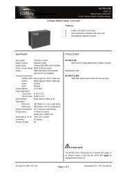
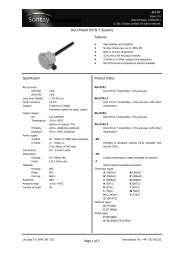
<strong>GS</strong>-S-xDate of Issue: 26/10/2012Issue Number: 5.0Page 1 of 3<strong>GS</strong>-S-x<strong>Internal</strong> <strong>Wall</strong> <strong>Mounted</strong> NO 2 , O 2 & SO 2 <strong>Sensors</strong>Features:Benefit:4-20mA outputWide supply voltage range (10 to 30Vdc)Excellent long term stabilityTamperproof lidTechnical OverviewThe <strong>GS</strong>-S-x series of wall mounting Nitrogen Dioxide (NO 2), Oxygen (O 2) and Sulphur Dioxide (SO 2) sensors are4-20mA current loop powered devices, with various sensing ranges of gas concentrations.The sensor has a normal working life of 2 years in air, and needs to be powered up within 6 months ofpurchase.Tel: +44 (0) 1732 861200. - E-mail: sales@sontay.com. - Web: www.sontay.com.© 2012 <strong>Sontay</strong> Limited. All rights reserved
<strong>GS</strong>-S-xDate of Issue: 26/10/2012Issue Number: 5.0Page 2 of 3Specification:Output ranges:<strong>GS</strong>-S-ND10 0-10ppm<strong>GS</strong>-S-OX25 0-15 to 25%<strong>GS</strong>-S-SD20 0-20ppmOutput4-20mASupply voltage10 to 30VdcResolution:<strong>GS</strong>-S-ND10
<strong>GS</strong>-S-xDate of Issue: 26/10/2012Issue Number: 5.0Page 3 of 3Installation:Antistatic precautions must be observed when handling these sensors. The PCB contains circuitry that can bedamaged by static discharge.1. Select a location which will give a representative sample of the prevailing space condition. The <strong>GS</strong>-S is notsuitable for external mounting.Avoid mounting the sensor in direct sunlight.2. It is recommended that the unit be mounted with the cable entry at the bottom.3. Remove the front cover by removing the tamperproof screw and twist the lid and separating from the main body.4. Using the base of the housing as a template mark the hole centres. Drill two pilot holes at 85mm (3.35“) centres inthe surface to which the sensor is to be mounted.5. Fix the sensor to the wall using appropriate screws, the housing is designed to make it easy for an electricalscrewdriver to be used if desired.6. Feed the cable through the gland and terminate at the terminal block. Leaving some slack inside the housing,tighten the cable gland onto the cable.7. Replace the lid after the electrical connections have been made, and re-fit the tamperproof screw.Connections:+Red:Black:10 to 30Vdc4-20mA outputWhilst every effort has been made to ensure the accuracy of this specification, <strong>Sontay</strong> cannot accept responsibility for damage, injury,loss or expense from errors or omissions. In the interest of technical improvement, this specification may be altered without notice.Tel: +44 (0) 1732 861200. - E-mail: sales@sontay.com. - Web: www.sontay.com.© 2012 <strong>Sontay</strong> Limited. All rights reserved