Intersil ISL6520ACBZ datasheet: pdf
Intersil ISL6520ACBZ datasheet: pdf
Intersil ISL6520ACBZ datasheet: pdf

Create successful ePaper yourself
Turn your PDF publications into a flip-book with our unique Google optimized e-Paper software.
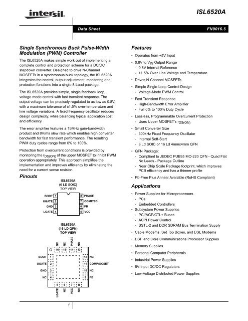
®ISL6520AData SheetFN9016.5Single Synchronous Buck Pulse-WidthModulation (PWM) ControllerThe ISL6520A makes simple work out of implementing acomplete control and protection scheme for a DC/DCstepdown converter. Designed to drive N-ChannelMOSFETs in a synchronous buck topology, the ISL6520Aintegrates the control, output adjustment, monitoring andprotection functions into a single 8-Lead package.The ISL6520A provides simple, single feedback loop,voltage-mode control with fast transient response. Theoutput voltage can be precisely regulated to as low as 0.8V,with a maximum tolerance of ±1.5% over-temperature andline voltage variations. A fixed frequency oscillator reducesdesign complexity, while balancing typical application costand efficiency.The error amplifier features a 15MHz gain-bandwidthproduct and 8V/ms slew rate which enables high converterbandwidth for fast transient performance. The resultingPWM duty cycles range from 0% to 100%.Protection from overcurrent conditions is provided bymonitoring the r DS(ON) of the upper MOSFET to inhibit PWMoperation appropriately. This approach simplifies theimplementation and improves efficiency by eliminating theneed for a current sense resistor.PinoutsBOOT 1UGATEGND23LGATE 4ISL6520A(6 LD SOIC)TOP VIEWISL6520A(16 LD QFN)TOP VIEW8 PHASE7 COMP/SD6 FB5 VCCFeatures• Operates from +5V Input• 0.8V to V IN Output Range- 0.8V Internal Reference- ±1.5% Over Line Voltage and Temperature• Drives N-Channel MOSFETs• Simple Single-Loop Control Design- Voltage-Mode PWM Control• Fast Transient Response- High-Bandwidth Error Amplifier- Full 0% to 100% Duty Cycle• Lossless, Programmable Overcurrent Protection- Uses Upper MOSFET’s r DS(ON)• Small Converter Size- 300kHz Fixed Frequency Oscillator- Internal Soft-Start- 8 Ld SOIC or 16 Ld 4mmx4mm QFN• QFN Package:- Compliant to JEDEC PUB95 MO-220 QFN - Quad FlatNo Leads - Package Outline- Near Chip Scale Package footprint, which improvesPCB efficiency and has a thinner profile• Pb-Free Plus Anneal Available (RoHS Compliant)Applications• Power Supplies for Microprocessors- PCs- Embedded Controllers• Subsystem Power Supplies- PCI/AGP/GTL+ Buses- ACPI Power Control- SSTL-2 and DDR SDRAM Bus Termination Supply• Cable Modems, Set Top Boxes, and DSL ModemsBOOTUGATEGNDNC1234NCNCPHASENC16 15 14 131211109NCCOMP/OCSETNCFB• DSP and Core Communications Processor Supplies• Memory Supplies• Personal Computer Peripherals• Industrial Power Supplies• 5V-Input DC/DC Regulators• Low-Voltage Distributed Power Supplies5 6 7 8LGATENCVCCNC1
ISL6520AOrdering InformationPARTNUMBERPARTMARKINGTEMP.RANGE(°C) PACKAGE PKG. DWG. #ISL6520ACB* 6520 ACB 0 to +70 8 Ld SOIC M8.15<strong>ISL6520ACBZ</strong>*(Note)<strong>ISL6520ACBZ</strong>A*(Note)6520 ACBZ 0 to +70 8 Ld SOIC(Pb-free)6520 ACBZ 0 to +70 8 Ld SOIC(Pb-free)M8.15M8.15ISL6520AIB* 6520 AIB -40 to +85 8 Ld SOIC M8.15ISL6520AIBZ*(Note)6520 AIBZ -40 to +85 8 Ld SOIC(Pb-free)M8.15ISL6520ACR* 65 20ACR 0 to +70 16 Ld 4x4mm QFN L16.4x4ISL6520ACRZ*(Note)65 20ACRZ 0 to +70 16 Ld 4x4mm QFN(Pb-free)L16.4x4ISL6520AIR* 65 20AIR -40 to +85 16 Ld 4x4mm QFN L16.4x4ISL6520AIRZ *(Note)ISL6520EVAL165 20AIRZ -40 to +85 16 Ld 4x4mm QFN(Pb-free)Evaluation BoardL16.4x4*Add “-T” suffix for tape and reel.NOTE: <strong>Intersil</strong> Pb-free plus anneal products employ special Pb-free material sets; molding compounds/die attach materials and 100% matte tin plate termination finish,which are RoHS compliant and compatible with both SnPb and Pb-free soldering operations. <strong>Intersil</strong> Pb-free products are MSL classified at Pb-free peak reflowtemperatures that meet or exceed the Pb-free requirements of IPC/JEDEC J STD-020.2 FN9016.5
ISL6520AAbsolute Maximum RatingsSupply Voltage, V CC . . . . . . . . . . . . . . . . . . . . . . . . . . . . . . . . +6.0VAbsolute Boot Voltage, V BOOT . . . . . . . . . . . . . . . . . . . . . . . +15.0VUpper Driver Supply Voltage, V BOOT - V PHASE . . . . . . . . 7.0V (DC)8.0V (