AUTOTRONICS LABORATORY (Automotive ... - Consult-Exim
AUTOTRONICS LABORATORY (Automotive ... - Consult-Exim
AUTOTRONICS LABORATORY (Automotive ... - Consult-Exim
- No tags were found...

Create successful ePaper yourself
Turn your PDF publications into a flip-book with our unique Google optimized e-Paper software.
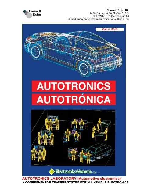
<strong>Consult</strong>-<strong>Exim</strong> Bt.1025 Budapest Törökvész út 58.Tel: 394-1811 Fax: 392-7118E-mail: info@consultexim.hu www.consultexim.hu<strong>AUTOTRONICS</strong> <strong>LABORATORY</strong> (<strong>Automotive</strong> electronics)A COMPREHENSIVE TRAINING SYSTEM FOR ALL VEHICLE ELECTRONICS
<strong>Consult</strong>-<strong>Exim</strong> Bt.1025 Budapest Törökvész út 58.Tel: 394-1811 Fax: 392-7118E-mail: info@consultexim.hu www.consultexim.hu
ADVANCED <strong>AUTOTRONICS</strong> <strong>LABORATORY</strong><strong>Consult</strong>-<strong>Exim</strong> Bt.1025 Budapest Törökvész út 58.Tel: 394-1811 Fax: 392-7118E-mail: info@consultexim.hu www.consultexim.hu
<strong>Consult</strong>-<strong>Exim</strong> Bt.1025 Budapest Törökvész út 58.Tel: 394-1811 Fax: 392-7118E-mail: info@consultexim.hu www.consultexim.huINTRODUCTIONModern vehicles rely increasingly on electronics for all aspects of their performance, and so electronics is avital part of the training for automotives technicians. <strong>AUTOTRONICS</strong> (<strong>Automotive</strong> Electronics) is simply aconvenient name for this important subject, covering all areas where electronic technology is used in motorvehicles. New subjects are arisen from the production programmes of the car industry, already involved in atransformation of the electrical control system used in cars. New service devices have beenintroduced and many of the older mechanical controls have been replaced with electrical or electronic onesfor some years now. Using innovatory technologies like microelectronics, telematics, software offers highersafety and comfort, besides improving energy saving and reducing pollution levels for a betterenvironment care. The following areas are those where electronics is of key importance:• Electronic ignition and injection with lower emissions• High Pressure Diesel engine control• Electronic braking control ABS and EBD for higher safety• Traction and stability control in order to improve drivability• Multiplex network wiring to enhance reliability• Dual zone air conditioning for better comfort• Satellite guidance systems• Standard computer diagnosis for customer service efficiencyThis situation has led to a major change in the skill and professional profiles, involving not only theautomotive production industry, but also all those involved in the related “maintenance area”, as follows:• Independent automotive repair and maintenance centre• Quick service shops• Aftermarket applications for equipments upgrade• Emissions and safety inspection performed by authoritiesThe <strong>Automotive</strong> Technician must continually adapt knowledge and know-howELETTRONICA VENETA & IN.EL., a world leading company in education, has designed and produced amulti-purpose computerized laboratory based on advanced and integrated educational solutions whichcomprehensively fulfils all the needs in this field, for all types and models of vehicles. The systems andtraining equipment are suitable for theoretical study, experiments and practical work, for training courses (ofone or more years), as well as for specialization and up-dating courses. Some of the equipment isparticularly suitable for classroom demonstrations.The industrial solutions designed by Elettronica Veneta & IN.EL. s.p.a. for education in<strong>AUTOTRONICS</strong> provide the users with the necessary tools for developing a comprehensive trainingprocess for the technicians in this field. It also offers the advantage of extending and/orcomplete courses of electronics-electrotechnicsmechanics, so that the trainees are up to date andneeded in the labour market.• Introductory training in general electronics and electronic components, related particularly to theautomotive industry.• Basic concepts of the operation of the main mechanical components and systems of cars are studied bymeans of software simulations designed for use under Windows.• Complete analysis of all the electric/electronic systems for controlling engine and transmissions in cars,including troubleshooting and setting up.• Use of the most advanced diagnostic systems applied in workshops on cars with the most sophisticatedtechnology.
<strong>Consult</strong>-<strong>Exim</strong> Bt.1025 Budapest Törökvész út 58.Tel: 394-1811 Fax: 392-7118E-mail: info@consultexim.hu www.consultexim.huThese aims can be achieved through:• A computerized interactive laboratory with experiment modules equipped with circuits and devices, for thestudy of general electronics and of actual and characteristic automotive components. Thanks to itsconfiguration this laboratory is an effective way to study the operating principles of the main sensors,transducers and actuators for the control of the engine and car’s movement. Other modules for the study ofgeneral electronics, digital electronics and microprocessors are also available for introductory courses ofelectronics, which can precede the explanation of specific autotronics topics.• A set of software packages which simulate the operation of mechanical and electrical systems, withspecific interactive software for each experiment module.• A complete set of training packages. Each package reproduces a specific electrical/electronic unit orsystem of the car, with actual components, so that tests and measurements can easily be carried out.In fact the whole electric and electronic system of a car is subdivided into various training packages,so that each system can be examined under real operational conditions.• The “training car”: a commercial car (models and features upon request), equipped with a PC-controlledsystem of fault insertion supported by an interactive software for stimulating and guiding students introubleshooting.• A complete set of computerized diagnostic tests for use onthe “training car”
There are 10 separate, «basic» (B) and «expansion» (E), packages :<strong>Consult</strong>-<strong>Exim</strong> Bt.1025 Budapest Törökvész út 58.Tel: 394-1811 Fax: 392-7118E-mail: info@consultexim.hu www.consultexim.huA01B : Internal combustion engines and checks• Four-stroke engine• Diesel engine• Timing diagram• ValveTimingA01E : expansion• Wankel engine• «Boxer» engine• Two-stoke engine• V-type engine• Balancing shafts• Hydraulic tappet• Adjustable camshaftA02B : gasoline (petrol) engines• Diaphragm pump• Roller pump• Downdraught carburetor• Single-Jetronic injectionA02E : expansion• ECOTRONIC carburettor• Air sensor with pump for• K-Jetronic injection• KE-Jetronic injection• L-Jetronic injection• MULTEC injection• Injectors and electronic injectorsA03B : Diesel engines fuel supply• Double delivery pump• Vane pump• Injector holder• Centrifugal speed governor for line pumpA03E : expansion• Multistage centrifugal blower• Spiral supercharger• Roots supercharger• Spark lead device for injection pump withdistributor• Speed governor for injection pump with distributor• Injection pump with electronic-controlled distributorA04B : clutch and manual transmission• Clutch with spiral spring• Four-gear transmissionA04E : expansion• Clutch• Clash gear transmission• Five-gear transmissionA05B : synchronization and automatictransmission• Synchronizing gear• Simple set of crown wheelsA05E : expansion• Transmission synchronization• Check of automatic transmission• Automatic transmission with pressure controA06B : cooling and lubrication• Centrifugal pump• Gear pumpA06E : expansion• Radiator cap• Thermostatic expansion valve• Visco- fan• Rotary pumpA07B : axles and wheel geometry• Sprung axles• Unsprung axles• Mac Pherson suspensions• Steering geometryA07E : expansion• Adjustable double-arm suspensions• Multi-link suspensions• Hydraulic-pneumatic suspension• Electronic control of shock absorber• Electronic power steeringA08B: hydraulic brakes• Double-servo drum brake• Disk brake with floating gage• Tandem brakeA08E : expansion• Brake booster• Solenoid valve for ABS• Braking controlA09B : pneumatic brakes• Single-cylinder air compressor• Pressure regulator• 4-circuit protection valve• Diaphragm-protection bellowsA09E : expansion• Two-circuit valve of service brake• Solenoid valve• Braking control• Pneumatic/electronic pressure-contro valve• Solenoid valve for ABSA10B : electric system• Ignition distributor• Ignition distributor with spark lead and lag• Centrifugal spark lead deviceA10E : expansion• Pulse generation• Starter motor• Three-phase AC generator• Collectorl
<strong>Consult</strong>-<strong>Exim</strong> Bt.1025 Budapest Törökvész út 58.Tel: 394-1811 Fax: 392-7118E-mail: info@consultexim.hu www.consultexim.hu
<strong>Consult</strong>-<strong>Exim</strong> Bt.1025 Budapest Törökvész út 58.Tel: 394-1811 Fax: 392-7118E-mail: info@consultexim.hu www.consultexim.huE.V. laboratories for Autotronics are conceived for the technicians’ training on all types of cars.
<strong>Consult</strong>-<strong>Exim</strong> Bt.1025 Budapest Törökvész út 58.Tel: 394-1811 Fax: 392-7118E-mail: info@consultexim.hu www.consultexim.huINTERACTIVE EXPERIMENTLABORATORIES for <strong>AUTOTRONICS</strong>The interactive experiment laboratory consists of a set of workstations.Each work-station includes:• Module holder Box - Power supply unit - Control unit -Experiment modulesConfigurationThe system configuration is very flexible to user requirements, so that laboratories with different functionsand performances can be prepared:Individual work-stations (self-learning mode):– theoretical and experimental study are developed withexperiment modules– insertion of faults and variations in the modules are controlledmanually: Control unit SIS1/EV– theoretical and experimental study are developed with experiment modules-insertion of faults andvariations in the modules are controlled by a microprocessor system:Control unit SIS2/EV– theoretical and experimental study being developed with experiment modules– insertion of faults and variations in the modules are carried out with a Personal Computer fitted with anappropriate interface card: Control unit SIS3/EV
<strong>Consult</strong>-<strong>Exim</strong> Bt.1025 Budapest Törökvész út 58.Tel: 394-1811 Fax: 392-7118E-mail: info@consultexim.hu www.consultexim.huInterconnected work-stations with a central monitoringstation for the Lecturer– Individual work-stations using the control unit SIS2/EV can be connected to the lecturer’s PersonalComputer, which enables him to organize all the learning activities of the student groups– Individual work-stations, each with the control unit SIS3/EV and a Personal Computer, equipped with thesoftware for an experiment, can be connected via a data network to a main console for the lecturer. Thisfully computerized classroom provides the ability to organize and control the entire learning process (C.B.T.– Computer Based Training)
<strong>Consult</strong>-<strong>Exim</strong> Bt.1025 Budapest Törökvész út 58.Tel: 394-1811 Fax: 392-7118E-mail: info@consultexim.hu www.consultexim.huPOWER SUPPLY UNIT mod. PS1-PSU/EVIt provides the d.c. voltage necessary to power the experiment modules and the control units mod. SIS1/EV,SIS2/EV and SIS3/EV. It consists in a container that creates an ergonomic unit with the module-holder boxmod. BOX/EV. On the silk screen front plate, there are the terminals and the LEDs for taking and display theoutput voltages. These are available on DIN connectors set on the rear side of the power supply. The powersupply unit is universal , as it is proper to power all kinds of modules produced by Elettronica Veneta &IN.EL. S.p.A. (Catalogues no. 20-A, 21-A, 33-A, 34-A)The supplied voltages are:• Output S1: +30Vdc – 4ARectified, filtered voltage protected with fuse. Voltage indicator LED• Output S2: 24Vac – 4A Protection with fuse Voltage indicator LED• Output S3: +5Vdc - 2A• Output S4: +12Vdc – 2A, -12Vdc – 1AStabilized voltage, electronically protected from short-circuits and overloads.Voltage indicator LED• Output S5: 1.3Vdc - 24Vdc, 1AStabilized voltage, electronically protected from short-circuits and overloads.Voltage indicator LED• Output on DIN connector: 24Vac – 0 – 24Vac, 0.5A Voltage protected with fuse(The outputs S1 and S2 provide 4A singularly and 2A if used simultaneously)• Power supply: 115/230 Vac, ±10%, 50/60 Hz• Max power: 150 VA• Dimensions: 415x185x195 mm• Weight: 3 KgMODULE-HOLDER BOX mod. BOX/EVSupport for housing the experiment modules and the individual control units mod. SIS1/EV, SIS2/EV andSIS3/EV.The modules and the individual control units can be fixed to the frame by using a “Plug-in” system.• Dimensions: 415x400x110 mm• Weight: 1Kg
<strong>Consult</strong>-<strong>Exim</strong> Bt.1025 Budapest Törökvész út 58.Tel: 394-1811 Fax: 392-7118E-mail: info@consultexim.hu www.consultexim.huMANUAL SYSTEM WITH CONTROL UNITMOD. SIS1/EVThe unit mod. SIS1/EV includes 24 switches for modifying each module circuits and for fault insertion.It is installed into the module holder box mod. BOX/EV by means of a plug-in system, together with themodules. The unit is fitted with a special universal connector for connection to any of the modules.Self-learning / laboratory modeThis unit is used for setting up work-stations for the student who, following the manuals supplied with themodules, can develop the various experiments. Faults and circuits variations can be inserted manually.Each student works independently on his own work-station. The experiment modules are connected to thecontrol unit mod. SIS1/EV, through which the faults, or the circuit variations are inserted manually. Themanuals supplied with the modules guide the student through all operations.Each station uses the power supply unit mod. PS1-PSU/EV and the module holder box mod. BOX/EV.Different student units in the same room enable a traditionaltype laboratory atmosphere to be created,where control and interaction with the lecturer are important complementary factors in optimizing learning.
<strong>Consult</strong>-<strong>Exim</strong> Bt.1025 Budapest Törökvész út 58.Tel: 394-1811 Fax: 392-7118E-mail: info@consultexim.hu www.consultexim.huSYSTEM WITH MICROPROCESSOR CONTROL UNITMOD. SIS2/EVThe unit mod. SIS2/EV consists of a CPU Z80, RAM and EPROM, 25-key keypad, liquid crystal display,circuits for faults insertion and also for variations to the parameters used in the experiment modules and RS-232 interface for connection to the lecturer’s PC.It is installed into the module holder box mod. BOX/EV by means of a plug-in system, together with themodules. The unit is fitted with a special universal connector, for connection to any module and it is poweredby the unit mod. PS1-PSU/EV.Self-learning modeThe unit mod. SIS2/EV is used to set up work-stations, where the student performs practical exercises withthe help of the manuals and under microprocessor control. Interaction is through a keypad and display fromwhich the student can:– select the required lesson code– answer the questions– obtain circuits variations– check the time taken to complete answers.Laboratory modeThe use of different units mod. SIS2/EV enables a complete laboratory to be set up, with work-stations forthe Lecturer and the students (up to a maximum of 32). Each student works independently on his workstationunder the control of the unit mod. SIS2/EV. A station using a PC, is also provided for the lecturer forthe automatic collection of the students’ results (using control software mod. SW-X/EV).The experiment modules are connected to the control unit mod. SIS2/EV, through which the faults areinserted or the variations to circuits are made automatically.MINIMUM CONFIGURATION REQUIRED FORTHE MULTIMEDIA PERSONAL COMPUTER:• Pentium IV• 256 MB RAM• HD 40 GB• CD-ROM/DVD-ROM• Serial and parallel interface• Windows 98/2000/XP• Internet EXPLORER 5.0.• Network board.CLASS CONTROL Software mod. SW-X/EVThe software at the lecturer’s station is used for collecting and processing the students’ answers.Using the software, the lecturer can manage various classes, collect the results from the students’ stationsautomatically and keep a constant check on the level of learning attained by eachstudent. This software is the same as that used in the interactive multimedia system with control unitmod. SIS3/EV but the section mod. SIS2/EV is used.
<strong>Consult</strong>-<strong>Exim</strong> Bt.1025 Budapest Törökvész út 58.Tel: 394-1811 Fax: 392-7118E-mail: info@consultexim.hu www.consultexim.huThe experiment modules are the fundamental units of the system mod. IPES/EV. With them the student candevelop all the different types of work in the course, including the insertion of faults and variations to thecircuits. This provides a sound and efficient educational system. The modules contain a set of circuits whichhave already been set up, and are connected to the individual control units mod. SIS1/EV, SIS2/EV andSIS3/EV with the connector provided. The modules are individually inserted in the module holder boxmod. BOX/EV, and are powered by the unit mod. PS1-PSU/EV using a special universal connector.Each module is supplied with a manual which guides the student through the theory, the experiments andtroubleshooting. The complete list of modules is featured below, together with the relevant topics, includingall the electronics sectors covered by the system IPES/EV.
<strong>Consult</strong>-<strong>Exim</strong> Bt.1025 Budapest Törökvész út 58.Tel: 394-1811 Fax: 392-7118E-mail: info@consultexim.hu www.consultexim.huMod. MCM1/EV is one of the experiment modules in theInteractive Practical Electronics System - IPES.These modules take the learner, a step at a time,through one unit of electronics or telecommunications.They include both the necessary theory and practicalwork, which includes measurements, questions, insertionof circuit variations and faults. Laboratories can be set upwith great flexibility, devised to meet differentrequirements. Options range from the manual, standaloneunits, up to the fully computerized classroom. Eachmodule comprises a set of circuits and associatedexperiments. The module is connected to a control unit(mod. SIS1/EV, SIS2/EV or SIS3/EV). The control unitenables the level of learning to be assessed, and it alsocontrols fault insertions and circuit variations.The module is fitted in module holder box mod. BOX/EV.The unit mod. PS1-PSU/EV supplies the power.The manual provided guides the user through the theory,theexperiments and the analysis of circuit variations andtroubleshooting.MODULE MCM1/EVThe module provides all the theory for the fundamentallaws of dc and ac circuits. It contains all the componentsneeded to set up circuits for each particular subject.Different sections of the various circuits can be selectedusing jumper connections.BASIC ELECTRICITY IModule MCM1/EVLearning objectives• Electricity, units and symbols• The e.m.f. and the potential difference• The effects of the electrical current on the humanbody, safety measures• DC current, switches and relays• Power supplies and measuring instruments:voltmeter, amp-meter, ohmmeter, the multimeter• Ohm’s law• Series and parallel resistive circuits: current, voltageand resistance measurements• Kirchhoff’s laws: voltage, current and resistancecircuit calculation• Thevenin’s theorem: equivalent e.m.f. and seriesresistance calculation• Norton’s theorem: equivalent current and parallelresistance calculation• Superposition theorem• Rheostats and potentiometers• Power in DC• Power transferGeneral features• Printed circuit with protective treatment and silkscreen mimic diagram• System for quick fastening to module holder boxmod. BOX/EV• Dimensions: 386x24x40 mmElectrical characteristics• Fault simulation• Test and interconnection points, Ø 2 mm• Rapid modifications to circuits using jumpers• 37-pin connector to the control unit• 8-wire connector to the power supply unit mod. PS1-PSU/EV• Power supply: ±12Vdc - 0.5 A , 1.3-24Vdc – 0-2A varTheoretical experimental manualsThe module is supplied with a series of manuals asfollows:Student manual• A section dedicated to the theoretical treatment ofthe topics and to a description of the circuits• A section which acts as a guide to the user for thepractical experiments and taking measurements• A section on analyzing variations to the circuit, andon troubleshooting the programmed faultsLecturer’s guide• Wiring diagrams and description of operation• List of the correct answers to the questionsSoftware SW-D-MCM1/EVThis includes a series of lessons covering the topicsrequired for the practical circuits of this module.It is used with the control unit mod. SIS3/EV andprovides - through a multimedia graphical interface -the development of theoretical, experimental andpractical learning, including variations to the circuitand the automatic insertion of faults.
<strong>Consult</strong>-<strong>Exim</strong> Bt.1025 Budapest Törökvész út 58.Tel: 394-1811 Fax: 392-7118E-mail: info@consultexim.hu www.consultexim.huMod. MCM2/EV is one of the experiment modules in theInteractive Practical Electronics System - IPES.The IPES system takes the learner, a step at a time,through one unit of electronics or telecommunications.They include both the necessary theory and practicalwork, which includes measurements, questions, insertionof circuit variations and faults. Laboratories can be set upwith great flexibility, devised to meet differentrequirements. Options range from the manual, standaloneunits, up to the fully computerized classroom. Eachmodule comprises a set of circuits and associatedexperiments. The module is connected to a control unit,which is common for all modules: SIS1/EV, SIS2/EV orSIS3/EV. The control unit enables the level of learning tobe assessed, and it also controls fault insertions andvariations to the circuit.The module is fitted in module holder box mod. BOX/EV.The unit mod. PS1-PSU/EV supplies the power.The manual provided guides the user through the theory,theexperiments and the analysis of circuit variations andtroubleshooting.MODULE MCM2/EVThe module examines the behavior of the basiccomponents in ac circuits and the use of dc motors. Itcontains the components required to set up circuits foreach of the topics covered: inductance, capacitance,transformer, DC motor.Software SW-D-MCM2/EVThis includes a series of lessons covering the topicsrequired for thepractical circuits of this module.It is used with the control unit mod. SIS3/EV andprovides - through amultimedia graphical interface - the development oftheoretical,experimental and practical learning, including variationsto the circuitand the automatic insertion of faults.BASIC ELECTRICIY IIModule MCM2/EVLearning objectives• Magnetic fields• Electrical and electromagnetic fields• The capacitive effect and the capacitors: the energystorage, the current as a function of the voltageapplied to a capacitor• The inductive effect and the inductors: internalresistance measurement and experimental test of aninductor• AC resistive and capacitive circuits: the impedanceas a function of the frequency. Verifying the voltageand current phase shift in a condenser.• AC inductive circuits: the voltage and current phaseshift in an inductance, voltage and current withsinusoidal input. The reactance calculation of a coil.• The RLC circuit: the concept of circuit impedance,current and voltage measurement in RC, RL and RLCcircuits• Series and parallel resonance: the resonantfrequency measurement in parallel and series circuits,the Q factor of a series resonant circuit• AC power: active, reactive and apparent power.• The transformer: no-load and under load tests. Thetransformer ratio measurement• The autotransformer• DC electrical motors: the speed as a function of theapplied armature voltage, and the current as afunction of the applied load.• The electrical motor as an electrical generator.General features• Printed circuit with protective treatment and silkscreen mimic diagram• System for quick fastening to module holder boxmod. BOX/EV• Dimensions: 386x248x40 mmElectrical characteristics• Fault simulation• Test and interconnection points, Ø 2 mm• Rapid modifications to circuits using jumpers• 37-pin connector to the control unit• 8-wire connector to the power supply unit mod. PS1-PSU/EV• Power supply: ±12Vdc - 0.5 A, 1.3-24Vdc – 0-2 Avar, +5Vdc - 2A, 2x24Vac- 0.5ATheoretical-experimental manualsThe module is supplied with a series of manuals asfollows:Student manual• A section dedicated to the theoretical treatment ofthe topics and to a description of the circuits• A section which acts as a guide to the user for thepractical experiments and taking measurements• A section on analyzing variations to the circuit, andon troubleshooting the programmed faultsLecturer’s guide• Wiring diagrams and description of operation• List of the correct answers to the questions
<strong>Consult</strong>-<strong>Exim</strong> Bt.1025 Budapest Törökvész út 58.Tel: 394-1811 Fax: 392-7118E-mail: info@consultexim.hu www.consultexim.huELECTROMAGNETISMModule MCM2A/EVMod. MCM2A/EV is one of the experiment modules in theInteractive Practical Electronics System - IPES.These modules take the learner, a step at a time, throughone unit of electronics or telecommunications. They includeboth the necessary theory and practical work, whichincludes measurements, questions, insertion of circuitvariations and faults. Laboratories can be set up with greatflexibility, devised to meet different requirements. Optionsrange from the manual, stand-alone units, up to the fullycomputerized classroom. Each module comprises a set ofcircuits and associated experiments. The module isconnected to a control unit (mod. SIS1/EV, SIS2/EV orSIS3/EV) that enables the level of learning to be assessed,and it also controls fault insertions and variations to thecircuit. The module is fitted in module holder box mod.BOX/EV. The unit mod. PS1-PSU/EV supplies the power.The manual provided guides the user through the theory,the experiments and the analysis of circuit variations andtroubleshooting.MODULE MCM2A/EVThe module includes a set of electromagnetic elements forevaluating the magnetic effects of current andexperimenting the effects of electromagnetic induction.Learning objectives• Permanent magnets and ferromagnetic metals• Curie point• Magnetic field and spectrum• Magnetic permeability• Induced flux and measurement units• Electromagnetic induction, self-inducedelectromagnetic force• VDR suppressor used for eliminating disturbancesgenerated by CEMF (counter electromotive force)• Inductive reactance factor, phase angle• Mutual inductance in transformers, radio coils• Solenoids and magnets for relays, pick-up, dropout• The transformer• DC motors, voltage, current, speed, sense ofrotation• Hall effect sensors for speed measurement• Stepper motor: full step and half step drive withunipolar current,calculation of the number of steps• Application examples of the stepper motor.General features• Printed circuit with protective treatment and silkscreen mimic diagram• System for quick fastening to module holder boxmod. BOX/EV• Dimensions: 386x248x40 mmOther hardware features in this module• Fault simulation• Test and interconnection points, Ø 2 mm• Rapid modifications to circuits using jumpers• 37-pin connector to the control unit• 8-wire connector to the power supply unit mod.PS1-PSU/EV• Power supply: ±12Vdc - 0.5 ATheoretical-experimental manualsThe module is supplied with a series of manuals asfollows:Student manual• A section dedicated to the theoretical treatment ofthe topics and to a description of the circuits• A section which acts as a guide to the user for thepractical experiments and taking measurements• A section on analyzing variations to the circuit, andon troubleshooting the programmed faultsLecturer’s guide• Wiring diagrams and description of operation• List of the correct answers to the questionsSoftware SW-D-MCM2A/EVThis includes a series of lessons covering the topicsrequired for the practical circuits of this module.It is used with the control unit mod. SIS3/EV andprovides - through a multimedia graphical interface -the development of theoretical, experimental andpractical learning, including variations to the circuitand the automatic insertion of faults.
<strong>Consult</strong>-<strong>Exim</strong> Bt.1025 Budapest Törökvész út 58.Tel: 394-1811 Fax: 392-7118E-mail: info@consultexim.hu www.consultexim.huMod. MCM3/EV is one of the experiment modules inthe Interactive Practical Electronics System - IPES.These modules take the learner, a step at a time,through one unit of electronics or telecommunications.They include both the necessary theory and practicalwork, which includes measurements, questions,insertion of circuit variations and faults. Laboratoriescan be set up with great flexibility, devised to meetdifferent requirements. Options range from the manual,stand-alone units, up to the fully computerizedclassroom.Each module comprises a set of circuits and associatedexperiments. The module is connected to a control unit(mod. SIS1/EV, SIS2/EV or SIS3/EV) that enables thelevel of learning to be assessed, and it also controlsfault insertions and variations to the circuit.The module is fitted in module holder box mod.BOX/EV. The unit mod. PS1-PSU/EV supplies thepower.The manual provided guides the user through thetheory, theexperiments and the analysis of circuit variations andtroubleshooting.MODULE MCM3/EVThis module analyses the basic semiconductor-typedevices and their most common applications. Itcontains the components required to set up circuits foreach of thetopics covered: diodes, UJT, PUT, SCR, TRIAC, DIAC.Software mod. SW-D-MCM3/EVThis includes a series of lessons covering the topicsrequired for the practical circuits of this module.It is used with the control unit mod. SIS3/EV andprovides - through a multimedia graphical interface - thedevelopment of theoretical,experimental and practical learning, including variationsto the circuit and the automatic insertion of faults.ELECTRONIC DEVICES ANDCIRCUITS I Module MCM3/EVLearning objectives• Introduction to semiconductors: the conductibilitymechanism, semiconductors doping, majority andminority charge carriers.• P-N junction: diffusion and field currents, potentialbarrier.• P-N juction: direct and inverse polarization• The avalanche effect• The Zener effect• Diodes characteristics: direct and inverse conduction,the diode current as a function of the applied voltage,the V-I curve detection• Rectifiers: center-tapped secondary transformer, fullwave, Graetz bridge connection• Smoothing filters: capacitive and inductive filters,filters with LC, CLC and CRC configurations.• Voltage doubler• Clamping circuits: no-load and under load tests• Clipping circuits• Zener diode: differential resistance, output voltagestabilization according to the applied load and with theinput voltage variation.• UJT transistor: triangle and square wave generator• PUT: applications, frequency divider circuit.• SCR: holding current, device triggering and turnoff viaanode-gate and anode-cathode connections, triggeringcurve.• DIAC and TRIAC: DIAC characteristics, impulsegenerator, TRIAC bidirectional conductionGeneral features• Printed circuit with protective treatment and silkscreen mimic diagram• System for quick fastening to module holder box mod.BOX/EV• Dimensions: 386x248x40 mmOther hardware features in this module• Fault simulation• Test and interconnection points, Ø 2 mm• Rapid modifications to circuits using jumpers• 37-pin connector to the control unit• 8-wire connector to the power supply unit mod. PS1-PSU/EV• Power supply: ±12Vdc - 0.5 A, 1.3-24Vdc – 0-2 A var,2x24Vac- 0.5ATheoretical-experimental manualsThe module is supplied with a series of manuals asfollows:Student manual• A section dedicated to the theoretical treatment of thetopics and to a description of the circuits• A section which acts as a guide to the user for thepractical experiments and taking measurements• A section on analyzing variations to the circuit, and ontroubleshooting the programmed faultsLecturer’s guide• Wiring diagrams and description of operation• List of the correct answers to the questions
<strong>Consult</strong>-<strong>Exim</strong> Bt.1025 Budapest Törökvész út 58.Tel: 394-1811 Fax: 392-7118E-mail: info@consultexim.hu www.consultexim.huELECTRONIC DEVICES ANDCIRCUITS II Module MCM4/EVLearning objectives• NPN and PNP transistors: operation and fundamentalequations• Transistor static gain• Main curves: the collector and emitter currents relation• The JFET: (Field effect transistors), main curves,mutual characteristic and transconductance.• The MOSFET: MOSFET depletion, MOSFETenhancement, MOSFET and JFET comparison.• Amplifier with JFET, constant current generator andsmall signals amplifier.• Optoelectronic components: photorresistor ,photodiode, phototransistor, resistance/lumino sity andcurrent/luminosity curves.• Temperature transducers: resistance/tempera turecurve.• Transistor connections: common-emitter, commoncollectorand common-base amplifiers• Transistor biasing: circuit and output curve, graphicaland analytical methods for selecting the biasingcomponents.• Transistor operating areas• Bias circuit with only one power supply• Amplifiers classes, A,B and C• The Q point stabilization: thermal effects, stabilizationwith emitter resistance and with collector-baseresistance.• Stability parameters: the Vbe effect, beta gain effect,stabilization effect on the signals.General features• Printed circuit with protective treatment and silkscreen mimic diagram• System for quick fastening to module holder box mod.BOX/EV• Dimensions: 386x248x40 mmOther hardware features in this module:• Fault simulation• Test and interconnection points, Ø 2 mm• Rapid modifications to circuits using jumpers• 37-pin connector to the control unit• 8-wire connector to the power supply unit mod. PS1-PSU/EV• Power supply: ±12Vdc - 0.5 A, 1.3-24Vdc – 0-2A var,2x24Vac-0.5AMod. MCM4/EV is one of the experiment modules inthe Interactive Practical Electronics System - IPES.These modules take the learner, a step at a time,through one unit of electronics or telecommunications.They include both the necessary theory and practicalwork, which includes measurements, questions,insertion of circuit variations and faults. Laboratoriescan be set up with great flexibility, devised to meetdifferent requirements. Options range from the manual,stand-alone units, up to the fully computerizedclassroom. Each module comprises a set of circuits andassociated experiments. The module is connected to acontrol unit, which is common for all modules (SIS1/EV,SIS2/EV or SIS3/EV) that enables the level oflearning to be assessed, and it also controls faultinsertions and variations to the circuit.The module is fitted in module holder box mod.BOX/EV. The unit mod. PS1-PSU/EV supplies thepower. The manual provided guides the user throughthe theory, the experiments and the analysis of circuitvariations and troubleshooting.MODULE MCM4/EVThe module examines the features and biasingmethods of semiconductor devices.It comprises the components required to set up circuitsfor each of the topics covered: diodes, transistors,FETs, phototransistors, photodiodes, PTC, and NTCdevices.Theoretical-experimental manualsThe module is supplied with a series of manuals asfollows:Student manual• A section dedicated to the theoretical treatment of thetopics and to a description of the circuits• A section which acts as a guide to the user for thepractical experiments and taking measurements• A section on analyzing variations to the circuit, and ontroubleshooting the programmed faultsLecturer’s guide• Wiring diagrams and description of operation• List of the correct answers to the questionsSoftware SW-D-MCM4/EVThis includes a series of lessons which cover the topicsrequired for this module practical circuits. This is usedwith the control unit mod.SIS3/EV and provides - through a multimedia graphicalinterface – the development of theoretical, experimentaland practical learning, including variations to the circuitand the automatic insertion of faults.
<strong>Consult</strong>-<strong>Exim</strong> Bt.1025 Budapest Törökvész út 58.Tel: 394-1811 Fax: 392-7118E-mail: info@consultexim.hu www.consultexim.huLearning objectives• Small signal parameters: transistor equivalent circuitsfor commonemitter, common-collector and common-baseconfigurations; the “h” parameters definition andvariations.• The common-emitter characteristics with the “h”parameters• The bias parameters calculations• Measurement of the gain and the input capacity.• Input and output resistance measurement• Emitter followers• Double load amplifier: characteristics with the “h”parameters, voltage gain and phase shift, measurementof the input resistance Rit• RC coupling: selecting the number of stages, couplingtypes.• Transformer coupling: biasing, characteristics with the“h” parameters.• Direct coupling: characteristics with the “h” parameters.• Darlington connection: characteristics with the “h”parameters, saturation voltage.• Cascode and Bootstrap connections: characteristicswith the “h” parameters,• Differential amplifier: biasing, CMRR (Common ModeRejection Ratio), differential gain.• Class A amplifiers: output power, conversion efficiency.• Class B amplifiers: single-ended (with double andsingle feeder), push-pull configuration, power balance,cross-distortion• Complementary symmetry amplifiers: single and doublefeeder.• Class C amplifiers: with resistive load, matched.General features• Printed circuit with protective treatment and silk screenmimic diagram• System for quick fastening to module holder box mod.BOX/EV• Dimensions: 386x248x40 mmELECTRONIC DEVICES ANDCIRCUITS III Module MCM5/EVMod. MCM5/EV is one of the experiment modules inthe Interactive Practical Electronics System - IPES.The IPES system takes the learner, a step at a time,through one unit of electronics or telecommunications.They include both the necessary theory and practicalwork, which includes measurements, questions,insertion of circuit variations and faults.Laboratories can be set up with great flexibility,devised to meet different requirements. Options rangefrom the manual, stand-alone units, up to the fullycomputerized classroom. Each module comprises aset of circuits and associated experiments.The module is connected to a control unit, which iscommon for all modules (SIS1/EV, SIS2/EV orSIS3/EV) that enables the level of learning to beassessed, and it also controls fault insertions andvariations to the circuit.The module is fitted in moduleholder box mod. BOX/EV. The unit mod. PS1-PSU/EVsupplies the power. The manual provided guides theuser through the theory, the experiments and theanalysis of circuit variations and troubleshooting.MODULE MCM5/EVThe module analyses all the main types of transistoramplifier circuit. It contains the components requiredto set up circuits for each of the topics covered:diodes, transistors, inductances and transformers.Theoretical-experimental manualsThe module is supplied with a series of manuals asfollows:Student manual• A section dedicated to the theoretical treatment ofthe topics and to a description of the circuits• A section which acts as a guide to the user for thepractical experiments and taking measurements• A section on analyzing variations to the circuit, andon troubleshooting the programmed faultsLecturer’s guide• Wiring diagrams and description of operation• List of the correct answers to the questionsSoftware SW-D-MCM5/EVThis includes a series of lessons covering the topicsrequired for the practical circuits of this module.It is used with the control unit mod. SIS3/EV andprovides - through a multimedia graphical interface -the development of theoretical,experimental and practical learning, includingvariations to the circuit and the automatic insertion offaults.Other hardware features in this module:• Fault simulation• Test and interconnection points, Ø 2 mm• Rapid modifications to circuits using jumpers• 37-pin connector to the control unit• 8-wire connector to the power supply unit mod. PS1-PSU/EV• Power supply: ±12Vdc - 0.5 A, 1.3-24Vdc – 0-2 A var
<strong>Consult</strong>-<strong>Exim</strong> Bt.1025 Budapest Törökvész út 58.Tel: 394-1811 Fax: 392-7118E-mail: info@consultexim.hu www.consultexim.huMod. MCM6/EV is one of the experiment modules in theInteractive Practical Electronics System - IPES.The IPES system takes the learner, a step at a time,through one unit of electronics or telecommunications.They include both the necessarytheory and practical work, which includes measurements,questions, insertion of circuit variations and faults.Laboratories can be set up with great flexibility, devisedto meet different requirements. Options range from themanual, stand-alone units, up to the fully computerizedclassroom. Each module comprises a set of circuits andassociated experiments. The module is connected to acontrol unit, which is common for all modules (SIS1/EV,SIS2/EV or SIS3/EV) that enables the level oflearning to be assessed, and it also controls faultinsertions and variations to the circuit.The module is fitted in module holder box mod. BOX/EV.The unit mod. PS1-PSU/EV supplies the power.The manual provided guides the user through the theory,the experiments and the analysis of circuit variations andtroubleshooting.MODULE MCM6/EVThe module examines oscillating circuits, monostable,bistable and astable multivibrators. It contains thecomponents required to set up circuits for each of thetopics covered: diodes, transistors and inductances.General features• Printed circuit with protective treatment and silk screenmimic diagram• System for quick fastening to module holder box mod.BOX/EV• Dimensions: 386x248x40 mmELECTRONIC DEVICES ANDCIRCUITS IV Module MCM6/EVLearning objectives• RC and Wien bridge oscillators: phase shift oscillatoror RC, collector resistance variation.• Colpitts oscillator: oscillating frequency as a functionof L and C and the feeding voltage.• Hartley oscillator: collector and emitter feedbackmode• Meissner oscillator.• Quartz oscillator: frequency stability, quartzequivalent circuit, JBT quartz oscillator, oscillatingfrequency as a function of the feeding voltage.• Astable multivibrators• Monostable multivibrators:control circuit,performance with square wave input signal,synchronization impulses frequency, outputimpulse width.• Bistable multivibrators: control circuit andpropagation time, frequency divider, max.commutation frequency• Schmitt trigger : parameters selection, outputvoltages, VTH and VTL threshold voltages, circuitresponse to triangular and sinusoidalwaves, commutation speed.Other hardware features in this module:• Fault simulation• Test and interconnection points, Ø 2 mm• Rapid modifications to circuits using jumpers• 37-pin connector to the control unit• 8-wire connector to the power supply unit mod. PS1-PSU/EV• Power supply: ±12Vdc - 0.5 A, 1.3-24Vdc – 0-2 A varTheoretical-experimental manualsThe module is supplied with a series of manuals asfollows:Student manual• A section dedicated to the theoretical treatment ofthe topics and to a description of the circuits• A section which acts as a guide to the user for thepractical experiments and taking measurements• A section on analyzing variations to the circuit, andon troubleshooting the programmed faultsLecturer’s guide• Wiring diagrams and description of operation• List of the correct answers to the questionsSoftware SW-D-MCM6/EVThis includes a series of lessons covering the topicsrequired for the practical circuits of this module.It is used with the control unit mod. SIS3/EV andprovides - through a multimedia graphical interface -the development of theoretical,experimental and practical learning, includingvariations to the circuit and the automatic insertion offaults.
<strong>Consult</strong>-<strong>Exim</strong> Bt.1025 Budapest Törökvész út 58.Tel: 394-1811 Fax: 392-7118E-mail: info@consultexim.hu www.consultexim.huOPERATIONAL AMPLIFIERSModule MCM7/EVLearning objectives• Typical parameters: gain, offset, CMRR, input andoutput impedance, slew rate, bandwidth for gain=1.• Inverting amplifier• Non-inverting amplifier• Adder amplifier• Difference amplifier• Integrator amplifier• Differentiator amplifier• Comparator amplifier• Logarithmic amplifier• Monostable multivibrator• Astable multivibrator• Sine oscillator• Waveform generator• Voltage/frequency converter• Low-pass filter• High-pass filter• Band-pass filterGeneral features• Printed circuit with protective treatment and silk screenmimic diagram• System for quick fastening to module holder box mod.BOX/EV• Dimensions: 386x248x40 mmOther hardware features in this module:• Fault simulation• Test and interconnection points, Ø 2 mm• Rapid modifications to circuits using jumpers• 37-pin connector to the control unit• 8-wire connector to the power supply unit mod. PS1-PSU/EV• Power supply: ±12Vdc - 0.5 ASoftware SW-D-MCM7/EVThis includes a series of lessons covering the topicsrequired for thepractical circuits of this module.It is used with the control unit mod. SIS3/EV andprovides - through amultimedia graphical interface - the development oftheoretical,experimental and practical learning, including variationsto the circuitand the automatic insertion of faults.Mod. MCM7/EV is one of the experiment modules inthe Interactive Practical Electronics System - IPES.The IPES system takes the learner, a step at a time,through one unit of electronics or telecommunications.They include both the necessary theory and practicalwork, which includes measurements, questions,insertion of circuit variations and faults.Laboratories can be set up with great flexibility,devised to meet different requirements. Options rangefrom the manual, stand-alone units, up to the fullycomputerized classroom. Each module comprises aset of circuits and associated experiments.The module is connected to a control unit, which iscommon for all modules (SIS1/EV, SIS2/EV orSIS3/EV) that enables the level of learning to beassessed, and it also controls fault insertions andvariations to the circuit. The module is fitted in moduleholder box mod. BOX/EV. The unit mod. PS1-PSU/EVsupplies the power. The manual provided guides theuser through the theory, the experiments and theanalysis of circuit variations and troubleshooting.MODULE MCM7/EVThe module analyses the parameters and numerouspossible configurations of operational amplifiers. Itcontains the components required to set up circuits foreach of the topics covered: diodes, transistors and opamps.Theoretical-experimental manualsThe module is supplied with a series of manuals asfollows:Student manual• A section dedicated to the theoretical treatment ofthe topics and to a description of the circuits• A section which acts as a guide to the user for thepractical experiments and taking measurements• A section on analyzing variations to the circuit, andon troubleshooting the programmed faultsLecturer’s guide• Wiring diagrams and description of operation• List of the correct answers to the questions
<strong>Consult</strong>-<strong>Exim</strong> Bt.1025 Budapest Törökvész út 58.Tel: 394-1811 Fax: 392-7118E-mail: info@consultexim.hu www.consultexim.huLearning objectives• Typical parameters of the logic families: current andvoltage characteristics, dissipated power, fan-in, fan-out,noise margin, propagation and transition times.• TTL logic family: electrical features, ON/OFF state,commutation, ECL sub-family• CMOS logic family: complementary output stage, HC andHCT CMOS series.• TTL-CMOS interface• CMOS-TTL interface• Boolean algebra: classes, logic prepositions, postulatesand theorems, logic functions• Combinational logic circuits: function minimization,Karnaugh maps • Flip-Flops (FF), sequential circuits: latchRS-FF, RS with clock FF, JKFF, JK Master –Slave FF, D type FF, T type FF, clockgenerator with logic ports.• Shift-registers: the SN 74LS95 IC• Coders and Decoders: decimal-BCD coder, BCD-decimaldecoder • Display driver and 7-segment display: BCD-7segment decoder, LED visualization devices, 7 segmentdisplay.• Adders, comparators and BCD selectors: binary adder,adders cascade-connection, 1-bit and 4-bit comparators,BCD preselectors.Theoretical-experimental manualsThe module is supplied with a series of manuals as follows:Student manual• A section dedicated to the theoretical treatment of thetopics and to a description of the circuits• A section which acts as a guide to the user for thepractical experiments and taking measurements• A section on analyzing variations to the circuit, and ontroubleshooting the programmed faultsLecturer’s guide• Wiring diagrams and description of operation• List of the correct answers to the questionsSoftware SW-D-MCM8/EVThis includes a series of lessons covering the topicsrequired for the practical circuits of this module.It is used with the control unit mod. SIS3/EV and provides -through a multimedia graphical interface - the developmentof theoretical, experimental and practical learning, includingvariations to the circuit and the automatic insertion of faults.DIGITAL ELECTRONICS IModule MCM8/EVMod. MCM8/EV is one of the experiment modulesin the Interactive Practical Electronics System(IPES). These modules take the learner, a step at atime, through one unit of electronics ortelecommunications. They include both thenecessary theory and practical work, which includesmeasurements, questions, insertion of circuitvariations and faults. Laboratories can be set upwith great flexibility, devised to meetdifferent requirements. Options range from themanual, stand-alone units, up to the fullycomputerized classroom. Each module comprises aset of circuits and associated experiments.The module is connected to a control unit, which iscommon for all modules (SIS1/EV, SIS2/EV orSIS3/EV) that enables the level of learning to beassessed, and it also controls fault insertions andvariations to the circuit. The module is fitted inmodule holder box mod. BOX/EV. The unitmod. PS1-PSU/EV supplies the power.The manual provided guides the user through thetheory, the experiments and the analysis of circuitvariations and troubleshooting.MODULE MCM8/EVThe module deals with the study of digital circuitsstarting from basic logic, and proceeding tocombinational and sequential logic networks.It contains the components required to set upcircuits for each of the topics covered: TTL andCMOS integrated circuits, diodes, 7-segmentdisplays and BCD selectors.General features• Printed circuit with protective treatment and silkscreen mimic diagram• System for quick fastening to module holder boxmod. BOX/EV• Dimensions: 386x248x40 mmOther hardware features in this module:• Fault simulation• Test and interconnection points, Ø 2 mm• Rapid modifications to circuits using jumpers• 37-pin connector to the control unit• 8-wire connector to the power supply unit mod.PS1-PSU/EV• Power supply: ±12Vdc - 0.5 A, +5Vdc - 2A
<strong>Consult</strong>-<strong>Exim</strong> Bt.1025 Budapest Törökvész út 58.Tel: 394-1811 Fax: 392-7118E-mail: info@consultexim.hu www.consultexim.huMod. MCM9/EV is one of the experiment modules inthe Interactive Practical Electronics System - IPES.The IPES system takes the learner, a step at a time,through one unit of electronics or telecommunications.They include both the necessary theory and practicalwork, which includes measurements, questions,insertion of circuit variations and faults. Laboratoriescan be set up with great flexibility, devised to meetdifferent requirements. Options range from the manual,stand-alone units, up to the fully computerizedclassroom. Each module comprises a set of circuits andassociated experiments. The module is connected to acontrol unit, which is common for all modules (SIS1/EV,SIS2/EV or SIS3/EV) that enables the level oflearning to be assessed, and it also controls faultinsertions and variations to the circuit.The module is fitted in module holder box mod.BOX/EV. The unit mod. PS1-PSU/EV supplies thepower. The manual provided guides the user throughthe theory, the experiments and the analysis of circuitvariations and troubleshooting.MODULE MCM9/EVThe module deals with some typical applications ofdigital circuits. It contains the components required toset up circuits for each of the topics covered: TTL andCMOS integrated circuits, diodes, 7-segmentdisplays and BCD selectorsDIGITAL ELECTRONICS IIIModule MCM9/EVLearning objectives• Multiplexer : applications, the SN 74LS153 I.C.• Demultiplexer: IN/OUT circuit, the SN 74LS155 I.C.,use as binarydecimal decoder.• Asynchronous and Synchronous counters: module-10counters, the 7490 counter.• Traffic light simulator: the 74LS90 counter, LEDinterface.• Counter/frequency meter• Digital transmission/reception systems: the NRZ code• Manchester code coding/decoding• Bi-phase code coding/decoding• 1-bit differential code coding/decodingGeneral features• Printed circuit with protective treatment and silkscreen mimic diagram• System for quick fastening to module holder box mod.BOX/EV• Dimensions: 386x248x40 mm• Additional modules (optional boards) are available forother applicationsOther hardware features in this module:• Fault simulation• Test and interconnection points, Ø 2 mm• Rapid modifications to circuits using jumpers• 37-pin connector to the control unit• 8-wire connector to the power supply unit mod. PS1-PSU/EV• Power supply: ±12Vdc - 0.5 ATheoretical-experimental manualsThe module is supplied with a series of manuals asfollows:Student manual• A section dedicated to the theoretical treatment of thetopics and to a description of the circuits• A section which acts as a guide to the user for thepractical experiments and taking measurements• A section on analyzing variations to the circuit, and ontroubleshooting the programmed faultsLecturer’s guide• Wiring diagrams and description of operation• List of the correct answers to the questionsSoftware SW-D-MCM9/EVThis includes a series of lessons covering the topicsrequired for the practical circuits of this module.It is used with the control unit mod. SIS3/EV andprovides - through a multimedia graphical interface - thedevelopment of theoretical, experimental and practicallearning, including variations to the circuit and theautomatic insertion of faults.
<strong>Consult</strong>-<strong>Exim</strong> Bt.1025 Budapest Törökvész út 58.Tel: 394-1811 Fax: 392-7118E-mail: info@consultexim.hu www.consultexim.huMod. Z1/EV is one of the experiment modules in theInteractive Practical Electronics System - IPES.The IPES system takes the learner, a step at a time,through one unit of electronics or telecommunications. Theyinclude both the necessary theory and practical work, whichincludes measurements, questions, insertion of circuitvariations and faults. Laboratories can be set up with greatflexibility, devised to meet different requirements. Optionsrange from the manual, stand-alone units, up to the fullycomputerized classroom. Each module comprises a set ofcircuits and associated experiments. The module isconnected to a control unit, which is common for allmodules (SIS1/EV, SIS2/EV or SIS3/EV) that enables thelevel of learning to be assessed, and it also controls faultinsertions and variations to the circuit.The module is fitted in module holder box mod. BOX/EV.The unit mod. PS1-PSU/EV supplies the power.The manual provided guides the user through the theory,the experiments and the analysis of circuit variations andtroubleshooting.General features• Printed circuit with protective treatment and silk screenmimic diagram• System for quick fastening to module holder box mod.BOX/EV• Dimensions: 386x248x40 mm• Additional modules (optional boards) are available forother applications.8-BIT MICROPROCESSORModule Z1/EVMODULE Z1/EVThe module mod. Z1/EV is an educational systembased on the Z80 version of a microprocessor. It isdesigned for an introductory study ofmicroprocessor and of 8-bit systems in particular.The module includes all the componentscharacteristic of this kind of system (Z80microprocessor, RAM and EPROM, keyboard anddisplay, serial and parallel interfaces, analogueinputs and outputs and a fault control system).The system is equipped with a considerable numberof digital and analogue interfaces, thus enabling itsapplication to different sectors. The machine codeinstructions representing, the program to bedeveloped, are usually inserted from the keyboardand shown on the module display.When the applications to be developed are toocomplex, the system can be connected to aPersonal Computer by creating aDevelopment system with the following phases:• Program insertion into the PC in Assembler usinga text Editor• Program compiling and linking for the machinecode transformation made by microprocessor• Program transfer via serial or parallel interface intothe RAM of the microprocessor system• Program debug phase directly on themicroprocessor module with the module hardwaresources• Transfer of the perfectly operating and completelyPC tested program to an Eprom programmer for thedefinitive programming of the Eprom and itsinsertion into the proper base of themicroprocessor systemLearning objectives• Programming 8-bit microprocessor systems.• Monitor program instructions and commands.• Analysis of the hardware structure• Memory devices (RAM-EPROM)• Expansion of the signals of the data and addressbus : interfacing and programming.• Bus signals monitoring• Interfacing with serial external devices: Z80-SIO,structure and programming, RS232 serial interfaceapplication.• Interfacing with parallel external devices: Z80-PIO,structure and programming, application with 2parallel bidirectional programmable ports.• Keyboard and 7-segment display management.• Analogue-to-digital and digital-to-analogueconverters• Troubleshooting in microprocessor system• Preprogrammed available routines• Programming examples.
<strong>Consult</strong>-<strong>Exim</strong> Bt.1025 Budapest Törökvész út 58.Tel: 394-1811 Fax: 392-7118E-mail: info@consultexim.hu www.consultexim.huOther hardware features in this module:• Z80 microprocessor, 2.5 MHz• 4-KB EPROM system• 4-KB EPROM user• 2-KB RAM (expandable to 4 KB)• Keyboard with 20 function and 16 hexadecimal keys• 6-digit display (7-segments)• Buzzer• Tape-recorder interface• PIO interface (2 ports, 8 bits)• SIO interface (RS-232)• Expansion BUS interface• Analogue output: 8-bit D/A converter• Analogue input: 8-bit A/D converter• Device for fault insertion (up to 8 faults, with lockingkey)• 6 logic probes for troubleshooting• Monitor program in EPROM with the followingcommands:– viewing and editing the content of the registers andmemory– introduction of breakpoints in the programs– loading and saving programs in assembler via PC.• Fault simulation• Test and interconnection points, Ø 2 mm• Rapid modifications to circuits using jumpers• 37-pin connector to the control unit• 8-wire connector to the power supply unit mod. PS1-PSU/EV• Power supply: ±12Vdc - 0.5 A, +5Vdc – 2AOptions• EPROM programmer• EPROM eraser• Prototype unitTheoretical-experimental manualsThe module is supplied with a series of manuals asfollows:Student manual• A section dedicated to the theoretical treatment of thetopics and to a description of the circuits• A section which acts as a guide to the user for thepractical experiments and taking measurements• A section on analyzing variations to the circuit, and ontroubleshooting the programmed faultsLecturer’s guide• Wiring diagrams and description of operation• List of the correct answers to the questionsDEVELOPMENT SOFTWAREProgram for editing, compiling, linking and paralleltransmission from Personal Computer to moduleZ10/EVSoftware SW-D-Z1/EVThis includes a series of lessons covering the topicsrequired for the practical circuits of this module.It is used with the control unit mod. SIS3/EV andprovides - through a multimedia graphical interface - thedevelopment of theoretical, experimental and practicallearning, including variations to the circuitand the automatic insertion of faults.
<strong>Consult</strong>-<strong>Exim</strong> Bt.1025 Budapest Törökvész út 58.Tel: 394-1811 Fax: 392-7118E-mail: info@consultexim.hu www.consultexim.huMod. Z10/EV is one of the experiment modules in theInteractive Practical Electronics System - IPES.The IPES system takes the learner, a step at a time,through one unit of electronics or telecommunications.They include both the necessary theory and practicalwork, which includes measurements, questions,insertion of circuit variations and faults.Laboratories can be set up with great flexibility, devisedto meet different requirements. Options range from themanual, stand-alone units, up to the fully computerizedclassroom. Each module comprises a set of circuits andassociated experiments. The module is connected to acontrol unit, which is common for allmodules (SIS1/EV, SIS2/EV or SIS3/EV) that enablesthe level of learning to be assessed, and it also controlsfault insertions and variations to the circuit.The module is fitted in module holder box mod.BOX/EV. The unit mod. PS1-PSU/EV supplies thepower. The manual provided guides the user throughthe theory, the experiments and the analysis of circuitvariations and troubleshooting.MICROCONTROLLERModule Z10/EVMODULE Z10/EVThe microcontroller is a microprocessor containing alldevices (CPU, EPROM, RAM, I/O devices) necessaryto a complete system. This enables whole systems withminimum hardware configurations. This favored theiruse in low cost and largely used fields (remotecontrols, controls systems, etc.).The usedmicrocontroller has an Eprom where the program to bedeveloped is loaded; this component version is used todevelop the applications because it enables the samecomponent to be reprogrammed many times. In theindustry, OTP (ONCE TIME PROGRAMMABLE)versions are used for mass production.The module implements all typical developmentoperations, with special care to the educationalaspects. The microcontroller applications can bedeveloped as follows:• Programs insertion into the PC in Assembler using aText editor• Program compiling and linking for machine codetransformation by the microcontroller• Program debug phase directly on the microprocessormodule with the same module hardware• Program erasing in a second microcontroller in use(Eprom erasing device of the module) to avail of aready component to be reprogrammed with thechanges and corrections detected in thedebug phaseLearning objectives• System programming with microcontrollers• The ST62E25 microcontroller, blocks diagram• Programming: registers, stack, EPROM memory,RAM memory.• Addressing modes: inherent, direct, indirectimmediate, relative to Program Counter, extended, bitdirected,test bit and jump.• Instruction set• Software tools: edit, assembler, linker.• Input/output ports: features, options, IN/OUT addressprogramming, applications.• Programming and use of the A/D conversion,management and use of the interruptions.• The D/A converter: programming and use.• Reset control: power-on reset, watchdog reset• Control of the WAIT and STOP state• Timer: operational modes, programming and use.• Serial Communications: standard RS232transmission/ reception, interface and programming.General features• Printed circuit with protective treatment and silkscreen mimic diagram• System for quick fastening to module holder box mod.BOX/EV• Dimensions: 386x248x40 mm• Additional modules (optional boards) are available forother application
<strong>Consult</strong>-<strong>Exim</strong> Bt.1025 Budapest Törökvész út 58.Tel: 394-1811 Fax: 392-7118E-mail: info@consultexim.hu www.consultexim.huOther hardware features in this module:• Microcontroller: ST62E25• Maximum clock frequency: 8MHz• User EPROM: 3876 bytes• User RAM: 64 bytes• Interface for PC programming• Digital input line• Digital output lines• Analog input lines (8-bit A/D converter with 16 inputs)• Analog output line with D/A converter• Display, LED and keys• RS-232 serial interface• 10 faults• Software: assembler for microcontroller and transferprogram• Fault simulation• Test and interconnection points, Ø 2 mm• Rapid modifications to circuits using jumpers• 37-pin connector to the control unit• 8-wire connector to the power supply unit mod. PS1-PSU/EV• Power supply: ±12Vdc - 0.5 A, +5Vdc – 2AOptional items• EPROM programmer• EPROM eraser• prototype unitTheoretical-experimental manualsThe module is supplied with a series of manuals asfollows:Student manual• A section dedicated to the theoretical treatment of thetopics and to a description of the circuits• A section which acts as a guide to the user for thepractical experiments and taking measurements• A section on analyzing variations to the circuit, and ontroubleshooting the programmed faultsLecturer’s guide• Wiring diagrams and description of operation• List of the correct answers to the questionsDEVELOPMENT SOFTWAREProgram for editing, compiling, linking and paralleltransmission from Personal Computer to moduleZ10/EVSoftware SW-D-Z10/EVThis includes a series of lessons covering the topicsrequired for the practical circuits of this module.It is used with the control unit mod. SIS3/EV andprovides - through a multimedia graphical interface - thedevelopment of theoretical, experimental and practicallearning, including variations to the circuitand the automatic insertion of faults.
<strong>Consult</strong>-<strong>Exim</strong> Bt.1025 Budapest Törökvész út 58.Tel: 394-1811 Fax: 392-7118E-mail: info@consultexim.hu www.consultexim.huMod. MCM10/EV is one of the experiment modules in theInteractive Practical Electronics System - IPES.The IPES system takes the learner, a step at a time, throughone unit of electronics or telecommunications. They includeboth the necessary theory and practical work, which includesmeasurements, questions, insertion of circuit variations andfaults. Laboratories can be set up with great flexibility, devisedto meet different requirements. Options range from themanual, stand-alone units, up to the fully computerizedclassroom. Each module comprises a set of circuits andassociated experiments. The module is connected to a controlunit, which is common for all modules (SIS1/EV, SIS2/EV orSIS3/EV) that enables the level of learning to be assessed,and it also controls fault insertions and variations to the circuit.The module is fitted in module holder box mod. BOX/EV. Theunit mod. PS1-PSU/EV supplies the power. The manualprovided guides the user through the theory, theexperiments and the analysis of circuit variations andtroubleshooting.MODULE MCM10/EVThe module introduces the components generally used inindustrial applications: timers, regulators, optic and displaycomponents. It contains the components required to set upcircuits for each of the topics covered: diodes, transistors,phototransistors, TTL and CMOS integrated circuits, LCDdisplays and 7-segment displays.INDUSTRIAL ELECTRONICS IModule MCM10/EVLearning objectives• Fixed voltage regulation: fundamentalparameters, load change, input voltage variation,input ripple rejection, current regulator as afunction of the load, output voltage as a functionof the load current regulator.• Variable output regulators: output voltage andreference voltage ratio, input ripple rejectio,current regulator as a function of the applied load.• The 555 timer: monostable and astableconfigurations, PWM modulator.• LCD characteristics• LCD display driver• Optoisolators: correspondence factor,parameters of the optical coupling system.• Infrared reception/transmission: circuitapplicationsGeneral features• Printed circuit with protective treatment and silkscreen mimic diagram• System for quick fastening to module holder boxmod. BOX/EV• Dimensions: 386x248x40 mmOther hardware features in this module:• Fault simulation• Test and interconnection points, Ø 2 mm• Rapid modifications to circuits using jumpers• 37-pin connector to the control unit• 8-wire connector to the power supply unit mod.PS1-PSU/EV• Power supply: ±12Vdc - 0.5 A, +5Vdc – 2ATheoretical-experimental manualsThe module is supplied with a series of manualsas follows:Student manual• A section dedicated to the theoretical treatmentof the topics and to a description of the circuits• A section which acts as a guide to the user forthe practical experiments and takingmeasurements• A section on analyzing variations to the circuit,and on troubleshooting the programmed faultsLecturer’s guide• Wiring diagrams and description of operation• List of the correct answers to the questionsSoftware SW-D-MCM10/EVThis includes a series of lessons covering thetopics required for the practical circuits of thismodule. It is used with the control unit mod.SIS3/EV and provides - through amultimedia graphical interface - the developmentof theoretical, experimental and practicallearning, including variations to the circuitand the automatic insertion of faults.
<strong>Consult</strong>-<strong>Exim</strong> Bt.1025 Budapest Törökvész út 58.Tel: 394-1811 Fax: 392-7118E-mail: info@consultexim.hu www.consultexim.huLearning objectives• Diodes rectifying: operation with resistive load, with RC, RLloads, rectified output current and voltage, ripple.• SCR controlled rectifying: firing circuit, Zener diodes,operation with resistive and RL load.• PWM modulation: application circuits.• MOSFET H-bridge: channel N and P MOSFET driver• Voltage series regulation: application circuits• Switching-type voltage regulator: Flyback and Forwardtypes, application circuits.General features• Printed circuit with protective treatment and silk screenmimic diagram• System for quick fastening to module holder box mod.BOX/EV• Dimensions: 386x248x40 mmOther hardware features in this module:• Fault simulation• Test and interconnection points, Ø 2 mm• Rapid modifications to circuits using jumpers• 37-pin connector to the control unit• 8-wire connector to the power supply unit mod. PS1-PSU/EV• Power supply: ±12Vdc - 0.5 A, 1.3-24Vdc – 0-2 A varTheoretical-experimental manualsThe module is supplied with a series of manuals as follows:Student manual• A section dedicated to the theoretical treatment of the topicsand to a description of the circuits• A section which acts as a guide to the user for the practicalexperiments and taking measurements• A section on analyzing variations to the circuit, and ontroubleshooting the programmed faultsLecturer’s guide• Wiring diagrams and description of operation• List of the correct answers to the questionsSoftware SW-D-MCM11/EVThis includes a series of lessons covering the topics requiredfor the practical circuits of this module.It is used with the control unit mod. SIS3/EV and provides -through a multimedia graphical interface - the development oftheoretical, experimental and practical learning, includingvariations to the circuit and the automatic insertion of faults.POWER ELECTRONICSModule MCM11/EVMod. MCM11/EV is one of the experimentmodules in the Interactive Practical ElectronicsSystem - IPES. The IPES system takes thelearner, a step at a time, through one unitof electronics or telecommunications. Theyinclude both the necessary theory and practicalwork, which includes measurements, questions,insertion of circuit variations and faults.Laboratories can be set up with great flexibility,devised to meet different requirements. Optionsrange from the manual, stand-aloneunits, up to the fully computerized classroom.Each module comprises a set of circuits andassociated experiments. The module isconnected to a control unit, which is common forall modules (SIS1/EV, SIS2/EV or SIS3/EV) thatenables the level of learning to be assessed, andit also controls fault insertions and variations tothe circuit. The module is fitted in module holderbox mod. BOX/EV. The unit mod. PS1-PSU/EVsupplies the power. The manual provided guidesthe user through the theory, the experiments andthe analysis of circuit variations andtroubleshooting.MODULE mod. MCM11/EVThe module deals with power rectifiers andvoltage regulators. It contains the componentsrequired to set up circuits for each of thetopics covered: diodes, transistors, SCRs,MOSFETs, phototransistors, CMOS integratedcircuits.
<strong>Consult</strong>-<strong>Exim</strong> Bt.1025 Budapest Törökvész út 58.Tel: 394-1811 Fax: 392-7118E-mail: info@consultexim.hu www.consultexim.huLIGHT AND TEMPERATURECONTROL Module MCM12/EVLearning objectives• Light sensors: photorresistor, photodiode, phototransistor.• Conditioning signal circuits for photorresistor, photodiode,phototransistor.• Temperature sensors: NTC thermistor, PTC thermistor andthermal resistance• Conditioning signal circuits for NTC thermistor, PTCthermistor and thermal resistance• The automatic control: reference signal, error calculus,power amplifier.• PID control: proportional, integral and derivative actions,combined PID actions.• The ON/OFF controller• The automatic control: blocks diagram, open-loop control,closedloop control, sensitivity, precision, response time,stability.• Automatic light control: open loop control and closed loopcontrol with PID controller.• Automatic temperature control: open loop control and closedloop control with PID controllerGeneral features• Printed circuit with protective treatment and silk screenmimic diagram• System for quick fastening to module holder box mod.BOX/EV• Dimensions: 386x248x40 mmOther hardware features in this module:• Fault simulation• Test and interconnection points, Ø 2 mm• Rapid modifications to circuits using jumpers• 37-pin connector to the control unit• 8-wire connector to the power supply unit mod. PS1-PSU/EV• Power supply: ±12Vdc - 0.5 A, 1.3-24Vdc – 0-2 A varts.Mod. MCM12/EV is one of the experimentmodules in the Interactive Practical ElectronicsSystem - IPES. The IPES system takes thelearner, a step at a time, through one unitof electronics or telecommunications. Theyinclude both the necessary theory and practicalwork, which includes measurements, questions,insertion of circuit variations and faults.Laboratories can be set up with great flexibility,devised to meet different requirements. Optionsrange from the manual, stand-alone units, up tothe fully computerized classroom. Each modulecomprises a set of circuits and associatedexperiments. The module is connected to acontrol unit, which is common for allmodules (SIS1/EV, SIS2/EV or SIS3/EV) thatenables the level of learning to be assessed, andit also controls fault insertions and variations tothe circuit. The module is fitted in module holderbox mod. BOX/EV. The unit mod. PS1-PSU/EVsupplies the power. The manual provided guidesthe user through the theory, the experiments andthe analysis of circuit variations andtroubleshooting.MODULE MCM12/EVThis module deals with the various types ofsensors and P.I.D. control systems. It containsthe components required to set up circuits foreach of the topics covered: diodes, transistors,phototransistors and integrated circuits.Theoretical-experimental manualsThe module is supplied with a series of manualsas follows:Student manual• A section dedicated to the theoretical treatmentof the topics and to a description of the circuits• A section which acts as a guide to the user forthe practical experiments and takingmeasurements• A section on analyzing variations to the circuit,and on troubleshooting the programmed faultsLecturer’s guide• Wiring diagrams and description of operation• List of the correct answers to the questionsSoftware SW-D-MCM12/EVThis includes a series of lessons covering thetopics required for the practical circuits of thismodule. It is used with the control unit mod.SIS3/EV and provides - through a multimediagraphical interface - the development oftheoretical, experimental and practical learning,including variations to the circuit and theautomatic insertion of fault
<strong>Consult</strong>-<strong>Exim</strong> Bt.1025 Budapest Törökvész út 58.Tel: 394-1811 Fax: 392-7118E-mail: info@consultexim.hu www.consultexim.huDC & SYNCHRONOUS – STEPPERMOTOR Module MCM13/EVLearning objectives• The DC permanent magnet motor: torque, speed andpower, the DC tachometer, application circuits.• Speed automatic control for DC motors: tachometersignal conditioning, set-point, error signal, PI control,amplifier, current control.• The synchronous motor with rotating inductor:application circuits• Stepping motor: unipolar full step and half-step driver.• Steps generation sequence: BCD-decimal decoder,motor wounds driver amplifier.General features• Printed circuit with protective treatment and silk screenmimic diagram• System for quick fastening to module holder box mod.BOX/EV• Dimensions: 386x248x40 mmOther hardware features in this module:• Fault simulation• Test and interconnection points, Ø 2 mm• Rapid modifications to circuits using jumpers• 37-pin connector to the control unit• 8-wire connector to the power supply unit mod. PS1-PSU/EV• Power supply: ±12Vdc - 0.5 A, +5Vdc – 2ATheoretical-experimental manualsThe module is supplied with a series of manuals asfollows:Student manual• A section dedicated to the theoretical treatment of thetopics and to a description of the circuits• A section which acts as a guide to the user for thepractical experiments and taking measurements• A section on analyzing variations to the circuit, and ontroubleshooting the programmed faultsLecturer’s guide• Wiring diagrams and description of operation• List of the correct answers to the questionsMod. MCM13/EV is one of the experiment modules inthe Interactive Practical Electronics System - IPES.The IPES system takes the learner, a step at a time,through one unit of electronics or telecommunications.They include both the necessary theory and practicalwork, which includes measurements, questions,insertion of circuit variations and faults.Laboratories can be set up with great flexibility,devised to meet different requirements. Options rangefrom the manual, stand-alone units, up to the fullycomputerized classroom. Each module comprises aset of circuits and associated experiments.The module is connected to a control unit, which iscommon for all modules (SIS1/EV, SIS2/EV orSIS3/EV) that enables the level of learning to beassessed, and it also controls fault insertions andvariations to the circuit. The module is fitted in moduleholder box mod. BOX/EV. The unit mod. PS1-PSU/EVsupplies the power. The manual provided guides theuser through the theory, the experiments and theanalysis of circuit variations and troubleshooting.MODULE MCM13/EVThe module analyses dc, synchronous and steppingmotors. It contains the components required to set upcircuits for each of the topics covered: diodes,transistors, integrated circuits, dc and steppingmotors.Software SW-D-MCM13/EVThis includes a series of lessons covering the topicsrequired for the practical circuits of this module.It is used with the control unit mod. SIS3/EV andprovides – through a multimedia graphical interface -the development of theoretical, experimental andpractical learning, including variations to the circuitand the automatic insertion of faults.
<strong>Consult</strong>-<strong>Exim</strong> Bt.1025 Budapest Törökvész út 58.Tel: 394-1811 Fax: 392-7118E-mail: info@consultexim.hu www.consultexim.huEXPERIMENT MODULESThe experiment modules are the basic units of the interactive experimental laboratory for Autotronics. Inusing them, the student performs all the exercises in the course, including technical explanation, insertion offaults and variations to the circuits. This provides a sound and highly effective educationalsystem. The modules contain a set of circuits which have already been set up, and can be connected to theindividual control units SIS1/EV, SIS2/EV and SIS3/EV with the connector provided. The modules areindividually inserted in the module holder box mod. BOX/EV and are directly supplied with power from themod. PS1-PSU/EV unit (powering the whole set of modules) through a special universal connector.Each module is supplied with a coursebook which guides the student through the theory, the experimentsand fault-finding. The complete list of modules, including the relevant topics which cover all the autotronicssector, is shown on the following page.
<strong>Consult</strong>-<strong>Exim</strong> Bt.1025 Budapest Törökvész út 58.Tel: 394-1811 Fax: 392-7118E-mail: info@consultexim.hu www.consultexim.huGeneral features• Printed circuit with protective scratch-proof treatmentand silkscreen- printed mimic diagram• Rear part of printed circuit protected with a plastic panel• System for quick fastening to the module holder boxmod. BOX/EV• 2 mm Interconnection and test points• Power supply: 5 VDC – 2 A, ± 12 VDC - 0.5 A (Powersupply unit PS1-PSU/EV)• 37-pin connector for connection to the Control Unit• 8-wire/270° connector for connection to the powersupply unit mod. PS1-PSU/EV• Dimensions: 386x248x40 mmHardware features• Potentiometric air-flow transducer with adjustable rangeof 0 to 10 KW• Warning light of minimum opening of butterfly valve• Pressure transducer of 0 to 2 bar• Linearity 0.15%• External unit for generating pressure, consisting of ametallic support with cylinder, adjusting knob, transducerand pressure gauge with scale of 0 to 2.5 bar• Dimensions of external unit: 330x120x120 mmCoursebooksThe module comes with a coursebook which includes:– a section which provides a theoretical treatment of thetopics and describes the circuit – a section which acts asa guide to the learner for the practical experiments andfor taking measurements, adjustments and calibrations ofelectrical devices and electronic circuits – a section onlocating the programmed faultsOPTIONSEducational software mod. SW-D-AT1/EVThis can be used with the Control unit SIS3/EV and itprovides the development of theoretical, experimentaland practical learning, including the insertion of faults,using the PC.Set of instruments for analysis and diagnosis– Unit equipped with function generator, multimeter andfrequencymeter– Dual-trace oscilloscopeEXPERIMENT MODULEmod. AT01/EV Engine load sensorsThe mod. AT01/EV module is one of the experimentmodules in the Interactive Autotronics Laboratory.These modules provide the learner with a goodunderstanding of the operating principles ofsubsystems and devices found in the electrical andelectronic systems of modern cars.The circuits in these modules are not for any onespecific model or make of car, but they doreproduce the functions and performances of thesubsystems and devices used by theleading manufacturers of automotive components.Each module comprises a set of preassembledcircuits, with relevant mimic diagram, and isconnected (through an appropriate connector) to theControl Unit, which is common for all modules (mod.SIS1/EV, SIS2/EV or SIS3/EV). The control unitcontrols fault insertion and the variations to the circuit.This configuration allows the desired learningmode to be chosen: options range from an individualunit to the fully computerized classroom with teachercontrol. Each module is fitted into the module holderbox mod. BOX/EV by means of a plug-in system. Aunique connector provides the connection to thepower supply unit mod. PS1-PSU/EV, which iscommon to all modules. The coursebook providedguides the learner through the theory, experimentsand troubleshooting.EXPERIMENT MODULE mod. AT01/EVEngine load sensorsThis module gives a theoretical and experimentalstudy of the pressure and air-flow sensors used inelectronic injection systems of cars.Learning objectives• Characteristic features of engine load transducers• Definition of characteristic parameters• Electronic injection• Stoichiometric air-fuel ratio• Piezoelectric pressure transducer of the feedingmanifold• Resistive transducer of the air flow in the manifold• Conditioning of sensors• Electronic components• Characteristic curves• Linearity of transducers• Position of sensors in the engine system• Fault-findingOther Autotronics modules:• Sensors and car transducers of :Modules: AT02/EV-AT03/EV-AT04/EV-AT05/EV• Actuators for control systems:Modules: AT06/EV-AT07/EV-AT08/EV-AT09/EV• Engine control:Modules: AT10/EV-A-T11/EV• Instruments and auxiliary circuits:Modules: AT14/EV-AT15/EV-AT16/EV-AT17/EV
Electronics modules suitable for an introductorystudy to Autotronics.Other modules compatible with those of the previous set(power supply mod. PS1-PSU/EV, module holder boxmod. BOX/EV and control units SIS1, SIS2 or SIS3), areavailable as a study course forthe following areas:• Basic electricity• Semiconductor devices• Linear electronics• Digital electronics• Industrial electronics• Microprocessors<strong>Consult</strong>-<strong>Exim</strong> Bt.1025 Budapest Törökvész út 58.Tel: 394-1811 Fax: 392-7118E-mail: info@consultexim.hu www.consultexim.hu
<strong>Consult</strong>-<strong>Exim</strong> Bt.1025 Budapest Törökvész út 58.Tel: 394-1811 Fax: 392-7118E-mail: info@consultexim.hu www.consultexim.huEXPERIMENT MODULEmod. AT01/EV Engine load sensorsThe mod. AT02/EV module is one of the experimentmodules in the Interactive Autotronics Laboratory.These modules provide the learner with a goodunderstanding of the operating principles of subsystemsand devices found in the electrical and electronicsystems of modern cars. The circuits in thesemodules are not for any one specific model or makeof car, but they do reproduce the functions andperformances of the subsystems and devices usedby the leading manufacturers of automotivecomponents. Each module comprises a set ofpreassembled circuits, with relevant mimic diagram, andis connected (through an appropriate connector) to theControl Unit, which is common for all modules (mod.SIS1/EV, SIS2/EV or SIS3/EV). The control unit controlsfault insertion and the variations to the circuit. Thisconfiguration allows the desired learning mode to bechosen: options range from an individual unit to the fullycomputerized classroom with teacher control. Eachmodule is fitted into the module holder box mod. BOX/EVby means of a plug-in system. A unique connectorprovides the connection to the power supply unit mod.PS1-PSU/EV, which is common to all modules. Thecoursebook provided guides the learner through thetheory, experiments and troubleshooting.EXPERIMENT MODULE mod. AT02/EVSpeed and position sensorsThis module gives the theoretical and experimentalanalysis of speed and position sensors of the engineused in electronic injection systems for cars.Learning objectives• R.p.m. measurement of the drive shaft• Inductive proximity sensor for flywheel• Variable reluctance• Measuring/processing the engine r.p.m.• Hall effect• Hall effect applied to position sensors• Synchronization of ignition• Position of Top Dead Center• Conditioning of sensors• TroubleshootingGeneral features• Printed circuit with protective scratch-proof treatmentand silkscreen- printed mimic diagram• Rear part of printed circuit protected with a plasticpanel• System for quick fastening to the module holder boxmod. BOX/EV• Interconnection and test points of 2 mm• Power supply: 5 VDC – 2 A, ± 12 VDC - 0.5 A(Power supply unit mod. PS1-PSU/EV)• 37-pin connector for connection to the Control Unit• 8-wire/270° connector for connection to the powersupply unit mod. PS1-PSU/EV• Dimensions: 386x248x40 mmHardware features• Inductive transducer: Passive electromagneticpickup Winding resistance: 680 WInductance at 1000 Hz: 295 mH• Hall-effect transducer:Operate point: 420 GaussRelease point: 300 Gauss• Speed adjustable from 0 to 6000 rpm• 20-point bargraph LED for displaying rpm• LED for displaying the Top Dead Center• External unit provided with 20-teeth flywheel, notchfor detecting the TDC, motor, inductive sensor andHall-effect sensor• PWM control of engine speed• Dimensions of external unit: 155x125x120 mmCoursebooksThe module comes with a coursebook which includes:– a section which provides a theoretical treatment ofthe topics and describes the circuit– a section which acts as a guide to the learner for thepractical experiments and for taking measurements,adjustments and calibrations of electrical devices andelectronic circuits– a section on locating the programmed faultsOPTIONSEducational software mod. SW-D-AT2/EVThis can be used with the Control unit SIS3/EV and itprovides the development of theoretical, experimentaland practical learning, including the insertion of faults,using a PC.Set of instruments for analysis and diagnosis– Unit equipped with function generator, multimeterand frequency-meter– Dual-trace oscilloscopeOther Autotronics modules:• Car sensors and transducers :Modules: AT01/EV-AT03/EV-AT04/EV-AT05/EV• Actuators used in control systems:Modules: AT06/EV-AT07/EV-AT08/EV-AT09/EV• Engine control:Modules: AT10/EV-A-T11/EV• Instruments and auxiliary circuits:Modules: AT14/EV-AT15/EV-AT16/EV-AT17/EV
Set of electronics modules for an introductory studyto Autotronics.Other modules compatible with those of the previous set(power supplymod. PS1-PSU/EV, module holder box mod. BOX/EVand control unitsSIS1, SIS2 or SIS3), are available as a study course forthe following areas:• Basic electricity• Semiconductor devices• Linear electronics• Digital electronics• Industrial electronics• Microprocessors<strong>Consult</strong>-<strong>Exim</strong> Bt.1025 Budapest Törökvész út 58.Tel: 394-1811 Fax: 392-7118E-mail: info@consultexim.hu www.consultexim.hu
<strong>Consult</strong>-<strong>Exim</strong> Bt.1025 Budapest Törökvész út 58.Tel: 394-1811 Fax: 392-7118E-mail: info@consultexim.hu www.consultexim.huThe mod. AT02/EV module is one of the experimentmodules in the Interactive Autotronics Laboratory.These modules provide the learner with a goodunderstanding of the operating principles of subsystemsand devices found in the electrical and electronic systemsof modern cars. The circuits in these modules are notfor any one specific model or make of car, butthey do reproduce the functions and performances ofthe subsystems and devices used by the leadingmanufacturers of automotive components. Each modulecomprises a set of preassembled circuits, with relevantmimic diagram, and is connected (through an appropriateconnector) to the Control Unit, which is common for allmodules (mod. SIS1/EV, SIS2/EV or SIS3/EV). Thecontrol unit controls fault insertion and the variations to thecircuit. This configuration allows the desired learning modeto be chosen: options range from an individual unit to thefully computerized classroom with teacher control. Eachmodule is fitted into the module holder box mod. BOX/EVby means of a plug-in system. A unique connectorprovides the connection to the power supply unit mod. PS1-PSU/EV, which is common to all modules. The coursebookprovided guides the learner through the theory,experiments and troubleshooting.EXPERIMENT MODULE mod. AT02/EVSpeed and position sensorsThis module gives the theoretical and experimental analysisof speed and position sensors of the engine used inelectronic injection systems for cars.Learning objectives• R.p.m. measurement of the drive shaft• Inductive proximity sensor for flywheel• Variable reluctance• Measuring/processing the engine r.p.m.• Hall effect• Hall effect applied to position sensors• Synchronization of ignition• Position of Top Dead Center• Conditioning of sensors• TroubleshootingEXPERIMENT MODULEmod. AT02/EV Speed and positionsensors for the engineGeneral features• Printed circuit with protective scratch-prooftreatment and silkscreen- printed mimic diagram• Rear part of printed circuit protected with a plasticpanel• System for quick fastening to the module holderbox mod. BOX/EV• Interconnection and test points of 2 mm• Power supply: 5 VDC – 2 A, ± 12 VDC - 0.5 A(Power supply unit mod. PS1-PSU/EV)• 37-pin connector for connection to the Control Unit• 8-wire/270° connector for connection to the powersupply unit mod. PS1-PSU/EV• Dimensions: 386x248x40 mmHardware features• Inductive transducer: Passive electromagneticpickup Winding resistance: 680 WInductance at 1000 Hz: 295 mH• Hall-effect transducer:Operate point: 420 GaussRelease point: 300 Gauss• Speed adjustable from 0 to 6000 rpm• 20-point bargraph LED for displaying rpm• LED for displaying the Top Dead Center• External unit provided with 20-teeth flywheel,notch for detecting the TDC, motor, inductivesensor and Hall-effect sensor• PWM control of engine speed• Dimensions of external unit: 155x125x120 mmCoursebooksThe module comes with a coursebook whichincludes:– a section which provides a theoretical treatment ofthe topics and describes the circuit– a section which acts as a guide to the learner forthe practical experiments and for takingmeasurements, adjustments andcalibrations of electrical devices and electroniccircuits– a section on locating the programmed faultsOPTIONSEducational software mod. SW-D-AT2/EVThis can be used with the Control unit SIS3/EV andit provides the development of theoretical,experimental and practical learning,including the insertion of faults, using a PC.Set of instruments for analysis and diagnosis– Unit equipped with function generator, multimeterand frequency-meter– Dual-trace oscilloscope
Other Autotronics modules:• Car sensors and transducers :Modules: AT01/EV-AT03/EV-AT04/EV-AT05/EV• Actuators used in control systems:Modules: AT06/EV-AT07/EV-AT08/EV-AT09/EV• Engine control:Modules: AT10/EV-A-T11/EV• Instruments and auxiliary circuits:Modules: AT14/EV-AT15/EV-AT16/EV-AT17/EVSet of electronics modules for an introductory study toAutotronics.Other modules compatible with those of the previous set(power supplymod. PS1-PSU/EV, module holder box mod. BOX/EV andcontrol unitsSIS1, SIS2 or SIS3), are available as a study course for thefollowing areas:• Basic electricity• Semiconductor devices• Linear electronics• Digital electronics• Industrial electronics• Microprocessors<strong>Consult</strong>-<strong>Exim</strong> Bt.1025 Budapest Törökvész út 58.Tel: 394-1811 Fax: 392-7118E-mail: info@consultexim.hu www.consultexim.hu
<strong>Consult</strong>-<strong>Exim</strong> Bt.1025 Budapest Törökvész út 58.Tel: 394-1811 Fax: 392-7118E-mail: info@consultexim.hu www.consultexim.huThe mod. AT03/EV module is one of the experimentmodules in the Interactive Autotronics Laboratory.These modules provide the learner with a goodunderstanding of the operating principles of subsystemsand devices found in the electrical and electronicsystems of modern cars. The circuits in thesemodules are not for any one specific model or makeof car, but they do reproduce the functions andperformances of the subsystems and devices usedby the leading manufacturers of automotivecomponents. Each module comprises a set ofpreassembled circuits, with relevant mimic diagram, andis connected (through an appropriate connector) to theControl Unit, which is common for all modules (mod.SIS1/EV, SIS2/EV or SIS3/EV). The control unit controlsfault insertion and the variations to the circuit. Thisconfiguration allows the desired learning mode to bechosen: options range from an individual unit to the fullycomputerized classroom with teacher control. Eachmodule is fitted into the module holder boxmod. BOX/EV by means of a plug-in system. A uniqueconnector provides the connection to the power supplyunit mod. PS1-PSU/EV, which is common to all modules.The coursebook provided guides the learner through thetheory, experiments and troubleshooting.EXPERIMENT MODULE mod. AT03/EV<strong>Automotive</strong> temperature sensorsThe module gives a theoretical and experimentalanalysis of temperature sensors used in automotiveelectronic control systems.Learning objectives• Technology: static sensors and thermal microswitches• Positive Temperature Coefficient (PTC) thermistors• CURIE temperature• Negative Temperature Coefficient (NTC) thermistors• Measuring interfaces with a resistance bridge• Measuring sequence with analog-to-digital converterand display with LED• Characteristic curves• Thermal microswitch for connecting the engine-coolingfan• Hysteresis characteristics of the of thermalmicroswitches• Fault-findingEXPERIMENT MODULEmod. AT03/EV Temperature sensorsGeneral features• Printed circuit with protective scratch-proof treatmentand silkscreen- printed mimic diagram• Rear part of printed circuit protected with a plasticpanel• System for quick fastening to the module holder boxmod. BOX/EV• Interconnection and test points of 2 mm• Power supply: 5 VDC – 2 A, ± 12 VDC - 0.5 A(Power supply unit mod. PS1-PSU/EV)• 37-pin connector for connection to the Control Unit• 8-wire/270° connector for connection to the powersupply unit mod. PS1-PSU/EV• Dimensions: 386x248x40 mmHardware features• Temperature control unit included in the module andprovided with heating element, cooling fan, NTC andPTC thermistors and thermal microswitch• Switch for the heating element• Switch for the cooling fan• Warning lights indicating the heating/cooling states• Temperature indicated with LED• Temperature thresholds of the thermal microswitchfor fan control: 78 ºC - 85 ºCCoursebooksThe module comes with a coursebook which includes:– a section which provides a theoretical treatment ofthe topics and describes the circuit– a section which acts as a guide to the learner for thepractical experiments and for taking measurements,adjustments and calibrations of electrical devices andelectronic circuits– a section on locating the programmed faultsOPTIONSEducational software mod. SW-D-AT3/EVThis can be used with the Control unit SIS3/EV and itprovides the development of theoretical, experimentaland practical learning, including the insertion of faults,using a PC.Set of instruments for analysis and diagnosis– Unit equipped with function generator, multimeterand frequencymeter– Dual-trace oscilloscopeOther Autotronics modules:• Car sensors and transducers:Modules: AT01/EV-AT02/EV-AT04/EV-AT05/EV• Actuators used in control systems:Modules: AT06/EV-AT07/EV-AT08/EV-AT09/EV• Engine control:Modules: AT10/EV-A-T11/EV• Instruments and auxiliary circuits:Modules: AT14/EV-AT15/EV-AT16/EV-AT17/EVElectronics modules suitable for an introductionto Autotronics.Other modules compatible with those of the previousset (power supply mod. PS1-PSU/EV, module holderbox mod. BOX/EV and control units SIS1, SIS2 orSIS3), are available as a study course for thefollowing areas: • Basic electricity, • Semiconductordevices • Linear electronic• Digital electronics• Industrial electronics• Microprocessors
<strong>Consult</strong>-<strong>Exim</strong> Bt.1025 Budapest Törökvész út 58.Tel: 394-1811 Fax: 392-7118E-mail: info@consultexim.hu www.consultexim.huThe mod. AT04/EV module is one of the experimentmodules in the Interactive Autotronics Laboratory.These modules provide the learner with a goodunderstanding of the operating principles of subsystemsand devices found in the electrical and electronicsystems of modern cars. The circuits in thesemodules are not for any one specific model or makeof car, but they do reproduce the functions andperformances of the subsystems and devices usedby the leading manufacturers of automotivecomponents. Each module comprises a set ofpreassembled circuits, with relevant mimic diagram,and is connected (through an appropriate connector) tothe Control Unit, which is common for all modules(mod. SIS1/EV, SIS2/EV or SIS3/EV). The control unitcontrols fault insertion and the variations to the circuit.This configuration allows the desired learning mode tobe chosen: options range from an individual unit to thefully computerized classroom with teacher control. Eachmodule is fitted into the module holder box mod.BOX/EV by means of a plug-in system. A uniqueconnector provides the connection to the power supplyunit mod. PS1-PSU/EV, which is common to allmodules. The coursebook provided guides thelearner through the theory, experiments andtroubleshooting.EXPERIMENT MODULE mod. AT04/EVOxygen and fuel level sensorThe module enables the theoretical and experimentalanalysis of oxygen and fuel level sensors used inautomotive electronic control systems.Learning objectives• Operating principle and technology of oxygen sensors• Composition of exhaust gases• Function of lambda probe• Electrical parameters of lambda probes• Characteristics of the variable frequency signal sentby the lambda probe• Variation of l ratio versus the air-fuel mixture• Control systems of mixture ratio to reduce thepolluting emissions• Fuel level transducers• Characteristic curves• Detection of fuel reserve level• TroubleshootingEXPERIMENT MODULE mod.AT04/EV Oxygen and fuel level sensorsGeneral features• Printed circuit with protective scratch-proof treatmentand silkscreen- printed mimic diagram• Rear part of printed circuit protected with a plasticpanel• System for quick fastening to the module holder boxmod. BOX/EV• Interconnection and test points of 2 mm• Power supply: 5 VDC – 2 A, ± 12 VDC - 0.5 A(Power supply unit mod. PS1-PSU/EV)• 37-pin connector for connection to the Control Unit• 8-wire/270° connector for connection to the powersupply unit mod. PS1-PSU/EV• Dimensions: 386x248x40 mmHardware features• Simulator of lambda probe with selector forvalues l = 1and less than and more than 1• LED for displaying the selected l state• Test points for measuring the voltage and frequencyof the l probe signal• Fuel level transducer: variable resistance• Fuel level indicator: 0, _ , 1• Reserve leve signaling with warning lightCoursebooksThe module comes with a coursebook which includes:– a section which provides a theoretical treatment of thetopics and describes the circuit– a section which acts as a guide to the learner for thepractical experiments and for taking measurements,adjustments and calibrations of electrical devices andelectronic circuits– a section on locating the programmed faultsOPTIONSEducational software mod. SW-D-AT4/EVThis can be used with the Control unit SIS3/EV and itprovides the development of theoretical, experimentaland practical learning, including the insertion of faults,using a PC.Set of instruments for analysis and diagnosis– Unit equipped with function generator, multimeter andfrequencymeter– Dual-trace oscilloscopeOther Autotronics modules:• Car sensors and transducers:Modules: AT01/EV-AT02/EV-AT03/EV-AT05/EV• Actuators used in control systems:Modules: AT06/EV-AT07/EV-AT08/EV-AT09/EV• Engine control: Modules: AT10/EV-A-T11/EV• Instruments and auxiliary circuits:Modules: AT14/EV-AT15/EV-AT16/EV-AT17/EVElectronics modules suitable for an introduction toAutotronics. Other modules compatible with those ofthe previous set (power supply mod. PS1-PSU/EV,module holder box mod. BOX/EV and control unitsSIS1, SIS2 or SIS3), are available as a study course forthe following areas:• Basic electricity • Semiconductor devices• Linear electronics • Digital electronics• Industrial electronics • Microprocessors
<strong>Consult</strong>-<strong>Exim</strong> Bt.1025 Budapest Törökvész út 58.Tel: 394-1811 Fax: 392-7118E-mail: info@consultexim.hu www.consultexim.huGeneral features• Printed circuit with protective scratch-proof treatmentand silkscreen- printed mimic diagram• Rear part of printed circuit protected with a plasticpanel• System for quick fastening to the module holder boxmod. BOX/EV• Interconnection and test points of 2 mm• Power supply: 5 VDC – 2 A, ± 12 VDC - 0.5 A(Power supply unit mod. PS1-PSU/EV)• 37-pin connector for connection to the Control Unit• 8-wire/270° connector for connection to the powersupply unit mod. PS1-PSU/EV• Dimensions: 386x248x40 mmHardware features• External unit for simulating a collision with gasoperatedspring• LED indicating collision• Piezoelectric transducer with warning lights indicatingcombustion and ignition control• Double radial inertial switch with intervention thresholdat a deceleration of 12 g and collision warning lights• LED indicating fuel pump operationCoursebooksThe module is supplied with a coursebook whichincludes:– a section which provides a theoretical treatment of thetopics and describes the circuit– a section which acts as a guide to the learner for thepractical experiments and for taking measurements,adjustments and calibrations of electrical devices andelectronic circuits– a section on locating the programmed faultsOther Autotronics modules:• Car sensors and transducers:Modules: AT01/EV-AT02/EV-AT03/EV-AT04/EV• Actuators used in control systems:Modules: AT06/EV-AT07/EV-AT08/EV-AT09/EV• Engine control: Modules: AT10/EV-A-T11/EV• Instruments and auxiliary circuits:Modules: AT14/EV-AT15/EV-AT16/EV-AT17/EVEXPERIMENT MODULEmod. AT05/EVCombustion and shock sensorsThe mod. AT05/EV module is one of the experimentmodules in the Interactive Autotronics Laboratory.These modules provide the learner with a goodunderstanding of the operating principles of subsystemsand devices found in the electrical and electronicsystems of modern cars. The circuits in thesemodules are not for any one specific model or makeof car, but they do reproduce the functions andperformances of the subsystems and devices usedby the leading manufacturers of automotivecomponents. Each module comprises a set ofpreassembled circuits, with relevant mimic diagram,and is connected (through an appropriate connector) tothe Control Unit, which is common for all modules(mod. SIS1/EV, SIS2/EV or SIS3/EV). The control unitcontrols fault insertion and the variations to the circuit.This configuration allows the desired learning mode tobe chosen: options range from an individual unit to thefully computerized classroom with teacher control. Eachmodule is fitted into the module holder boxmod. BOX/EV by means of a plug-in system. A uniqueconnector provides the connection to the power supplyunit mod. PS1-PSU/EV, which is common to allmodules. The coursebook provided guides thelearner through the theory, experiments andtroubleshooting.EXPERIMENT MODULE mod. AT05/EVCombustion and shock sensorsThe module enables the theoretical and experimentalanalysis of the shock sensors used in airbag systems,and of the combustion sensors used in electronicignition control.Learning objectives• Technology and operation of combustion knocktransducers of engine pistons• Electronic ignition control• Unidirectional shock sensor for airbag systems• Intervention angle• Multidirectional shock sensor for stopping the fuelpump• Localizaton of sensors in the car• TroubleshootingElectronics modules suitable for an introduction toAutotronics.Other modules compatible with those of the previousset (power supply mod. PS1-PSU/EV, module holderbox mod. BOX/EV and control units SIS1, SIS2 orSIS3), are available as a study course for the followingareas: • Basic electricity • Semiconductor devices• Linear electronics • Digital electronics• Industrial electronics • MicroprocessorsOPTIONS Educational software mod. SW-D-AT5/EVThis can be used with the Control unit SIS3/EV and itprovides the development of theoretical, experimentaland practical learning, including the insertion of faults,using a PC.Set of instruments for analysis and diagnosis– Unit equipped with function generator, multimeter andfrequencymeter– Dual-trace oscilloscope
<strong>Consult</strong>-<strong>Exim</strong> Bt.1025 Budapest Törökvész út 58.Tel: 394-1811 Fax: 392-7118E-mail: info@consultexim.hu www.consultexim.huThe mod. AT06/EV module is one of the experimentmodules in the Interactive Autotronics Laboratory.These modules provide the learner with a goodunderstanding of the operating principles of subsystemsand devices found in the electrical and electronicsystems of modern cars. The circuits in thesemodules are not for any one specific model or makeof car, but they do reproduce the functions andperformances of the subsystems and devices usedby the leading manufacturers of automotivecomponents. Each module comprises a set ofpreassembled circuits, with relevant mimic diagram, andis connected (through an appropriate connector) to theControl Unit, which is common for all modules (mod.SIS1/EV, SIS2/EV or SIS3/EV). The control unit controlsfault insertion and the variations to the circuit. Thisconfiguration allows the desired learning mode to bechosen: options range from an individual unit to the fullycomputerized classroom with teacher control. Eachmodule is fitted into the module holder box mod. BOX/EVby means of a plug-in system. A unique connectorprovides the connection to the power supply unit mod.PS1-PSU/EV, which is common to all modules. Thecoursebook provided guides the learner through thetheory, experiments and troubleshooting.EXPERIMENT MODULE mod. AT06/EVElectronic injectors - Solenoid valvesThe module enables the theoretical and experimentalanalysis of the injectors used in electronic injectionsystems for cars. Furthermore it includes equipment forthe recovery of fuel vapours driven by the solenoid valve.Learning objectives• Operating principles of electronic injection• Advantages of electronic injection• Construction and operation of electronic injectors• Electrical and mechanical characteristics of injectors• Linear and switching control of electronic injectors• Study of the recovery system of fuel vapors, to reducethe pollution from exhaust gases• Characteristics of the solenoid valve for recovery of fuelvapors• Fault-findingOther Autotronics modules:• Car sensors and transducers: Modules: AT01/EV-AT02/EV-AT03/EV-AT04/EV-AT05/EV• Actuators used in control systems:Modules: AT07/EV-AT08/EV-AT09/EV• Engine control: Modules: AT10/EV-A-T11/EV• Instruments and auxiliary circuits:Modules: AT14/EV-AT15/EV-AT16/EV-AT17/EVEXPERIMENT MODULEmod. AT06/EV Electronic injectors –Solenoid valvesGeneral features• Printed circuit with protective scratch-proof treatmentand silkscreen- printed mimic diagram• Rear part of printed circuit protected with a plasticpanel• System for quick fastening to the module holder boxmod. BOX/EV• Interconnection and test points of 2 mm• Power supply: 5 VDC – 2 A, ± 12 VDC - 0.5 A(Power supply unit mod. PS1-PSU/EV)• 37-pin connector for connection to the Control Unit• 8-wire/270° connector for connection to the powersupply unit mod. PS1-PSU/EV• Dimensions: 386x48x40 mmHardware features• Electronic injector - solenoid valve of recirculation,included in the module• Electronic fuel injector with a stroke of 0.15 mm• Control of speed simulator using a potentiometer,from 0 to 6000 r.p.m.• Opening pulse of injector adjustable from 1.5 to 15ms• Power stage driven by Intelligent Power Switch(Smart Power)• Switch for fault simulation in injectors• Detection and LED display of fault states in injectors:short circuit, open circuit• LED display of ON states of the solenoid valve forrecovery of fuel vapoursCoursebooksThe module comes with a coursebook which includes:– a section which provides a theoretical treatment ofthe topics and describes the circuit– a section which acts as a guide to the learner for thepractical experiments and for taking measurements,adjustments and calibrations of electrical devices andelectronic circuits– a section on locating the programmed faultsOPTIONSEducational software mod. SW-D-AT6/EVThis can be used with the Control unit SIS3/EV and itprovides the development of theoretical, experimentaland practical learning, including the insertion of faults,using a PC.Set of instruments for analysis and diagnosis– Unit equipped with function generator, multimeterand frequencymeter– Dual-trace oscilloscopeElectronics modules suitable for an introductionto Autotronics.Other modules compatible with those of the previousset (power supply mod. PS1-PSU/EV, module holderbox mod. BOX/EV and control units SIS1, SIS2 orSIS3), are available as a study course forthe following areas:• Basic electricity • Semiconductor devices• Linear electronics • Digital electronics• Industrial electronics • Microprocessors
<strong>Consult</strong>-<strong>Exim</strong> Bt.1025 Budapest Törökvész út 58.Tel: 394-1811 Fax: 392-7118E-mail: info@consultexim.hu www.consultexim.huThe mod. AT07/EV module is one of the experimentmodules in the Interactive Autotronics Laboratory.These modules provide the learner with a goodunderstanding of the operating principles of subsystemsand devices found in the electrical and electronicsystems of modern cars. The circuits in thesemodules are not for any one specific model or makeof car, but they do reproduce the functions andperformances of the subsystems and devices usedby the leading manufacturers of automotivecomponents. Each module comprises a set ofpreassembled circuits, with relevant mimic diagram, andis connected (through an appropriate connector) to theControl Unit, which is common for all modules (mod.SIS1/EV, SIS2/EV or SIS3/EV). The control unit controlsfault insertion and the variations to the circuit. Thisconfiguration allows the desired learning mode to bechosen: options range from an individual unit to the fullycomputerized classroom with teacher control. Eachmodule is fitted into the module holder box mod. BOX/EVby means of a plug-in system. A unique connectorprovides the connection to the power supply unit mod.PS1-PSU/EV, which is common to all modules. Thecoursebook provided guides the learner through thetheory, experiments and troubleshooting.EXPERIMENT MODULE mod. AT07/EVRelaysThis module gives a theoretical and experimentalanalysis of the control functions of car systems,particularly of relays or remote controlswitches.Learning objectives• Car’s wiring: size of leads• Low-power and high-power cables• Use of relays for arranging the wiring• Analysis of control logic with relays• Stop after an unsuccessful start• Battery switching and double starting• Stopping the starter with engine running• Thermal time switch for cold start• TroubleshootingOPTIONSEducational software mod. SW-D-AT7/EVThis can be used with the Control unit SIS3/EV and itprovides the development of theoretical, experimentaland practical learning, including the insertion of faultsusing a PC.Set of instruments for analysis and diagnosis– Unit equipped with function generator, multimeter andfrequencymeter – Dual-trace oscilloscopeEXPERIMENT MODULEmod. AT07/EV RelaysGeneral features• Printed circuit with protective scratch-proof treatmentand silkscreen- printed mimic diagram• Rear part of printed circuit protected with a plasticpanel • System for quick fastening to the moduleholder box mod. BOX/EV• Interconnection and test points of 2 mm• Power supply: 5 VDC – 2 A, ± 12 VDC - 0.5 A(Power supply unit mod. PS1-PSU/EV)• 37-pin connector for connection to the Control Unit• 8-wire/270° connector for connection to the powersupply unit mod. PS1-PSU/EV• Dimensions: 386x248x40 mmHardware features• «Start» pushbutton for simulating the start• Simulation of engine state with three LEDs• LED display of electronic injector for cold start• Starting temperature adjustable by means ofpotentiometer• Simulation of engine with speed adjusted bypotentiometer• LED display of fuel pump starting• Checks carried out with 3 relays included in themodule• Simulation of starter motors by means of three 10-point LED displaysCoursebooksThe module is supplied with a coursebook whichincludes:– a section which provides a theoretical treatment ofthe topics and describes the circuit– a section which acts as a guide to the learner for thepractical experiments and for taking measurements,adjustments and calibrations of electrical devices andelectronic circuits– a section on locating the programmed faultsOther Autotronics modules:• Car sensors and transducers: Modules: AT01/EV-AT02/EV-AT03/EV-AT04/EV-AT05/EV• Actuators used in control systems:Modules: AT06/EV-AT08/EV-AT09/EV• Engine control:Modules: AT10/EV-A-T11/EV• Instruments and auxiliary circuits:Modules: AT14/EV-AT15/EV-AT16/EV-AT17/EVElectronics modules suitable for an introductionto Autotronics.Other modules compatible with those of the previousset (power supply mod. PS1-PSU/EV, module holderbox mod. BOX/EV and control units SIS1, SIS2 orSIS3), are available as a study course forthe following areas:• Basic electricity• Semiconductor devices• Linear electronics• Digital electronics• Industrial electronics• Microprocessors
<strong>Consult</strong>-<strong>Exim</strong> Bt.1025 Budapest Törökvész út 58.Tel: 394-1811 Fax: 392-7118E-mail: info@consultexim.hu www.consultexim.huThe mod. AT08/EV module is one of the experimentmodules in the Interactive Autotronics Laboratory.These modules provide the learner with a goodunderstanding of the operating principles of subsystemsand devices found in the electrical and electronicsystems of modern cars. The circuits in thesemodules are not for any one specific model or makeof car, but they do reproduce the functions andperformances of the subsystems and devices usedby the leading manufacturers of automotivecomponents. Each module comprises a set ofpreassembled circuits, with relevant mimic diagram, andis connected (through an appropriate connector) to theControl Unit, which is common for all modules (mod.SIS1/EV, SIS2/EV or SIS3/EV). The control unit controlsfault insertion and the variations to the circuit. Thisconfiguration allows the desired learning mode to bechosen: options range from an individual unit to the fullycomputerized classroom with teacher control. Eachmodule is fitted into the module holder boxmod. BOX/EV by means of a plug-in system. A uniqueconnector provides the connection to the power supplyunit mod. PS1-PSU/EV, which is common to all modules.The coursebook provided guides the learner through thetheory, experiments and troubleshooting.EXPERIMENT MODULE mod. AT08/EVStatic switchesThe module enables the theoretical and experimentalanalysis of the static switches used in electronic ignitionsystems for cars. Furthermore, it describes the wholeignition cycle.Learning objectives• Operating principles of ignition• Analysis of electronic ignition by means of electronicstatic switches• Driving the ignition coil from a transistor• Analysis of engine ignition phases• Top Dead Center (T.D.C.) amd spark lead• Ignition coil: primary and secondary windings• Ignition oscillograms• Contactless ignition• Ignition distribution• TroubleshootingEXPERIMENT MODULEmod. AT08/EV Static switches for ignitionGeneral features• Printed circuit with protective scratch-proof treatmentand silkscreen- printed mimic diagram• Rear part of printed circuit protected with a plasticpanel• System for quick fastening to the module holder boxmod. BOX/EV• Interconnection and test points of 2 mm• Power supply: 5 VDC – 2 A, ± 12 VDC - 0.5 A(Power supply unit mod. PS1-PSU/EV)• 37-pin connector for connection to the Control Unit• 8-wire/270° connector for connection to the powersupply unit mod. PS1-PSU/EV• Dimensions: 386x248x40 mmHardware features• Simulation of inductive sensor for engine position• Speed adjusting potentiometer• Control transistor of coil primary winding• Voltage transformer• Display of ignition of spark plugs by means of fourLEDs• Display of the dynamics of engine cycle: explosion,compression, intake, exhaust, by means of 4 x 4 LEDmatrixCoursebooksThe module comes with a coursebook which includes:– a section which provides a theoretical treatment ofthe topics and describes the circuit– a section which acts as a guide to the learner for thepractical experiments and for taking measurements,adjustments and calibrations of electrical devices andelectronic circuits– a section on locating the programmed faultsOPTIONSEducational software mod. SW-D-AT8/EVThis can be used with the Control unit SIS3/EV and itprovides the development of theoretical, experimentaland practical learning, including the insertion of faults,using a PC.Set of instruments for analysis and diagnosis– Unit equipped with function generator, multimeterand frequencymeter– Dual-trace oscilloscopeOther Autotronics modules:• Car sensors and transducers: Modules: AT01/EV-AT02/EV-AT03/EV-AT04/EV- AT05/EV• Actuators used in control systems:Modules: AT06/EV-AT07/EV-AT09/EV• Engine control: Modules: AT10/EV-A-T11/EV• Instruments and auxiliary circuits:Modules: AT14/EV-AT15/EV-AT16/EV-AT17/EVElectronics modules suitable for an introductionto Autotronics.Other modules compatible with those of the previousset (power supply mod. PS1-PSU/EV, module holderbox mod. BOX/EV and control units SIS1, SIS2 orSIS3), are available as a study course for the followingareas:• Basic electricity • Semiconductor devices• Linear electronics • Digital electronics• Industrial electronics • Microprocessors
<strong>Consult</strong>-<strong>Exim</strong> Bt.1025 Budapest Törökvész út 58.Tel: 394-1811 Fax: 392-7118E-mail: info@consultexim.hu www.consultexim.huThe mod. AT09/EV module is one of the experimentmodules in the Interactive Autotronics Laboratory.These modules provide the learner with a goodunderstanding of the operating principles of subsystemsand devices found in the electrical and electronic systemsof modern cars. The circuits in these modules are notfor any one specific model or make of car, butthey do reproduce the functions and performances ofthe subsystems and devices used by the leadingmanufacturers of automotive components. Each modulecomprises a set of preassembled circuits, with relevantmimic diagram, and is connected (through an appropriateconnector) to the Control Unit, which is common for allmodules (mod. SIS1/EV, SIS2/EV or SIS3/EV). Thecontrol unit controls fault insertion and the variations to thecircuit. This configuration allows the desired learning modeto be chosen: options range from an individual unit to thefully computerized classroom with teacher control. Eachmodule is fitted into the module holder box mod. BOX/EVby means of a plug-in system. A unique connectorprovides the connection to the power supply unit mod. PS1-PSU/EV, which is common to all modules. The coursebookprovided guides the learner through the theory,experiments and troubleshooting.EXPERIMENT MODULE mod. AT09/EVIgnition actuatorsThis module provides the theoretical and experimentalanalysis of the various ignition techniques and technologyused in gasoline engines. Moreover, it explains thetechnology of Smart Power solid state relays.Learning objectives• Operating principles of ignition• Traditional ignition• Transistor-operated ignition• Ignition distributors• Contactless ignition• Capacitor-discharge ignition• Fully electronic ignition• Technology and operation of Smart Power static relays• TroubleshootingElectronics modules suitable for an introduction toAutotronics.Other modules compatible with those of the previous set(power supply mod. PS1-PSU/EV, module holder box mod.BOX/EV and control units SIS1, SIS2 or SIS3), areavailable as a study course for the following areas:• Basic electricity • Semiconductor devices• Linear electronics • Digital electronics• Industrial electronics • MicroprocessorsEXPERIMENT MODULEmod. AT09/EV Ignition actuatorsGeneral features• Circuit with protective scratch-proof treatment andsilk-screenprinted mimic diagram• Rear part of printed circuit protected with a plasticpanel• System for quick fastening to the module holderbox mod. BOX/EV• Interconnection and test points of 2 mm• Power supply: 5 VDC – 2 A, ± 12 VDC - 0.5 A(Power supply unit mod. PS1-PSU/EV)• 37-pin connector for connection to the Control Unit• 8-wire/270° connector for connection to the powersupply unit mod. PS1-PSU/EV• Dimensions: 386x248x40 mmHardware features• Motor for simulating engine revolutions• Operation of remote control switch effected bymeans of the motor, for signalling the Top DeadCenter• Configuration of the sensor for detecting theengine phases (using an inductive or Hall-effecttransducer)• Test points for measuring the current in theprimary winding of ignition coil• Simulation of the static electronic ignitiondistribution, with four LEDs• Thyristor switching for capacitor-discharge ignition• Configuration of assemblies using jumpersCoursebooksThe module is supplied with a coursebook whichincludes:– a section which provides a theoretical treatment ofthe topics and describes the circuit– a section which acts as a guide to the learner forthe practical experiments and for takingmeasurements, adjustments andcalibrations of electrical devices and electroniccircuits– a section on locating the programmed faultsOPTIONSEducational software mod. SW-D-AT8/EVThis can be used with the Control unit SIS3/EV andit provides the development of theoretical,experimental and practical learning,including the insertion of faults, using a PC.Set of instruments for analysis and diagnosis– Unit equipped with function generator, multimeterand frequencymeter– Dual-trace oscilloscopeOther Autotronics modules:• Car sensors and transducers: Modules: AT01/EV-AT02/EV-AT03/EV-AT04/EV-AT05/EV• Actuators used in control systems:Modules: AT06/EV-AT07/EV-AT08/EV• Engine control: Modules: AT10/EV-A-T11/EV• Instruments and auxiliary circuits:Modules: AT14/EV-AT15/EV-AT16/EV-AT17/EV
<strong>Consult</strong>-<strong>Exim</strong> Bt.1025 Budapest Törökvész út 58.Tel: 394-1811 Fax: 392-7118E-mail: info@consultexim.hu www.consultexim.huGeneral features• Printed circuit with protective scratch-proof treatmentand silkscreen- printed mimic diagram• Rear part of printed circuit protected with a plastic panel• System for quick fastening to the module holder boxmod. BOX/EV• Interconnection and test points of 2 mm• Power supply: 5 VDC – 2 A, ± 12 VDC - 0.5 A(Power supply unit mod. PS1-PSU/EV)• 37-pin connector for connection to the Control Unit• 8-wire/270° connector for connection to the powersupply unit mod. PS1-PSU/EV• Dimensions: 386x248x40 mmHardware features• Adjusting the input sensors with potentiometers• Simulation with variation of one or more sensors• Injection mapping parameters stored in EPROM, on themodule• Display of the memory address holding the conditionsdefined by sensors, by using eight LEDs• Test point for measuring the injection timecorresponding to environmental conditionsCoursebooksThe module comes with a coursebook which includes:– a section which provides a theoretical treatment of thetopics and describes the circuit– a section which acts as a guide to the learner for thepractical experiments and for taking measurements,adjustments and calibrations of electrical devices andelectronic circuits– a section on locating the programmed faultsOPTIONSEducational software mod. SW-D-AT10/EVThis can be used with the Control unit SIS3/EV and itprovides the development of theoretical, experimentaland practical learning, including the insertion of faults,using a PC.Set of instruments for analysis and diagnosis– Unit equipped with function generator, multimeter andfrequencymeter– Dual-trace oscilloscopeOther Autotronics modules:• Car sensors and transducers:Modules: AT01/EV-AT02/EV-AT03/EV-AT04/EV-AT05/EV• Actuators used in control systems:Modules: AT06/EV-AT07/EV-AT08/EV-AT09/EV• Engine control: Modules: A-T11/EV• Instruments and auxiliary circuits:Modules: AT14/EV-AT15/EV-AT16/EV-AT17/EVEXPERIMENT MODULEmod. AT10/EV Engine cold startThe mod. AT10/EV module is one of the experimentmodules in the Interactive Autotronics Laboratory.These modules provide the learner with a goodunderstanding of the operating principles ofsubsystems and devices found in the electricaland electronic systems of modern cars. The circuitsin these modules are not for any one specificmodel or make of car, but they do reproduce thefunctions and performances of the subsystemsand devices used by the leading manufacturers ofautomotive components. Each module comprises aset of preassembled circuits, with relevant mimicdiagram, and is connected (through an appropriateconnector) to the Control Unit, which is common for allmodules (mod. SIS1/EV, SIS2/EV or SIS3/EV). Thecontrol unit controls fault insertion and the variationsto the circuit. This configuration allows the desiredlearning mode to be chosen: options range from anindividual unit to the fully computerized classroom withteacher control. Each module is fitted into the moduleholder box mod. BOX/EV by means of a plug-insystem. A unique connector provides the connectionto the power supply unit mod. PS1-PSU/EV,which is common to all modules. The coursebookprovided guides the learner through the theory,experiments and troubleshooting.EXPERIMENT MODULE mod. AT10/EVCold start controlThis module gives the theoretical and experimentalanalysis of the parameters for the optimumperformance of electronic injection.Learning objectives• Advantages of electronic injection• Cold-enrichment of fuel• Stored mapping of injection values• Analysis of the parameters influencing the injectiontime on starting the engine• Influence of external temperature• Influence of the pressure in intake manifold• Influence of engine r.p.m.• Influence of coolant temperature• Fault-findingElectronics modules suitable for an introductionto Autotronics.Other modules compatible with those of the previousset (power supply mod. PS1-PSU/EV, module holderbox mod. BOX/EV and control units SIS1, SIS2 orSIS3), are available as a study course forthe following areas:• Basic electricity• Semiconductor devices• Linear electronics• Digital electronics• Industrial electronics• Microprocessors
<strong>Consult</strong>-<strong>Exim</strong> Bt.1025 Budapest Törökvész út 58.Tel: 394-1811 Fax: 392-7118E-mail: info@consultexim.hu www.consultexim.huEXPERIMENT MODULEmod. AT11/EVElectronic ignition controlThe mod. AT11/EV module is one of the experiment modulesin the Interactive Autotronics Laboratory. These modulesprovide the learner with a good understanding of theoperating principles of subsystems and devices found in theelectrical and electronic systems of modern cars. The circuitsin these modules are not for any one specific model ormake of car, but they do reproduce the functions andperformances of the subsystems and devices used by theleading manufacturers of automotive components. Eachmodule comprises a set of preassembled circuits, withrelevant mimic diagram, and is connected(through an appropriate connector) to the Control Unit, whichis common for all modules (mod. SIS1/EV, SIS2/EV orSIS3/EV). The control unit controls fault insertion and thevariations to the circuit. This configuration allows the desiredlearning mode to be chosen: options range from an individualunit to the fully computerized classroom with teacher control.Each module is fitted into the module holder boxmod. BOX/EV by means of a plug-in system. A uniqueconnector provides the connection to the power supply unitmod. PS1-PSU/EV, which is common to all modules. Thecoursebook provided guides the learner through the theory,experiments and troubleshooting.EXPERIMENT MODULE mod. AT11/EVElectronic ignition controlThis module enables the theoretical and experimentalanalysis of the control techniques and parameters used inautomotive electronic ignition systems.Learning objectives• Analysis of the characteristics of electronic ignition systems• Influence of engine speed• Influence of engine temperature• Influence of the type of fuel• Mapping of spark leads• Combustion shock or knocking• Closed-loop control of ignition in combustion knock state• Fault-fin dingElectronics modules suitable for an introduction toAutotronics.Other modules compatible with those of the previous set(power supply mod. PS1-PSU/EV, module holder box mod.BOX/EV and control units SIS1, SIS2 or SIS3), are availableas a study course for the following areas:• Basic electricity • Semiconductor devices• Linear electronics • Digital electronics• Industrial electronics • MicroprocessorsGeneral features• Printed circuit with protective scratch-prooftreatment and silkscreen- printed mimic diagram• Rear part of printed circuit protected with aplastic panel• System for quick fastening to the module holderbox mod. BOX/EV• Interconnection and test points of 2 mm• Power supply: 5 VDC – 2 A, ± 12 VDC - 0.5 A(Power supply unit mod. PS1-PSU/EV)• 37-pin connector for connection to the ControlUnit• 8-wire/270° connector for connection to thepower supply unit mod. PS1-PSU/EV• Dimensions: 386x248x40 mmHardware features• Adjusting the sensors with potentiometers• Mapping of the ignition times stored in EPROM,on the module• Display of spark lead time on 2-digit 7-segmentdisplay• Key for simulating the combustion shock• Closed-loop control of ignition in combustionwith knock effectCoursebooksThe module is supplied with a coursebook whichincludes:– a section which provides a theoretical treatmentof the topics and describes the circuit– a section which acts as a guide to the learnerfor the practical experiments and for takingmeasurements, adjustments andcalibrations of electrical devices and electroniccircuits– a section on locating the programmed faultsOPTIONSEducational software mod. SW-D-AT11/EVThis can be used with the Control unit SIS3/EVand it provides the development of theoretical,experimental and practical learning,including the insertion of faults, using a PC.Set of instruments for analysis and diagnosis– Unit equipped with function generator,multimeter and frequencymeter– Dual-trace oscilloscopeOther Autotronics modules:• Car sensors and transducers:Modules: AT01/EV-AT02/EV-AT03/EV-AT04/EV-AT05/EV• Actuators used in control systems:Modules: AT06/EV-AT07/EV-AT08/EV-AT09/EV• Engine control: Modules: A-T10/EV• Instruments and auxiliary circuits:Modules: AT14/EV-AT15/EV-AT16/EV-AT17/EV
<strong>Consult</strong>-<strong>Exim</strong> Bt.1025 Budapest Törökvész út 58.Tel: 394-1811 Fax: 392-7118E-mail: info@consultexim.hu www.consultexim.huThe mod. AT14/EV module is one of the experiment modulesin the Interactive Autotronics Laboratory. These modulesprovide the learner with a good understanding of theoperating principles of subsystems and devices found in theelectrical and electronic systems of modern cars. The circuitsin these modules are not for any one specific model ormake of car, but they do reproduce the functions andperformances of the subsystems and devices used by theleading manufacturers of automotive components. Eachmodule comprises a set of preassembled circuits, withrelevant mimic diagram, and is connected(through an appropriate connector) to the Control Unit, whichis common for all modules (mod. SIS1/EV, SIS2/EV orSIS3/EV). The control unit controls fault insertion and thevariations to the circuit. This configuration allows the desiredlearning mode to be chosen: options range from an individualunit to the fully computerized classroom with teacher control.Each module is fitted into the module holder boxmod. BOX/EV by means of a plug-in system. A specialconnector provides the connection to the power supply unitmod. PS1-PSU/EV, which is common to all modules. Thecoursebook provided guides thelearner through the theory, experiments and fault-finding.EXPERIMENT MODULE mod. AT14/EVProcessing and displayThe module enables the theoretical and experimental analysisof thedisplay techniques and technology used to inform the driver ofthefunctioning and condition of his car.Learning objectives• Processing the signals• 7-segment display of car speed• Analog bargraph displays• Characteristics of LEDs• Characteristics of liquid crystals• Positive and negative back-lighted LCD• Fault-findingElectronics modules suitable for an introduction toAutotronics.Other modules compatible with those of the previous set(power supply mod. PS1-PSU/EV, module holder box mod.BOX/EV and control units SIS1, SIS2 or SIS3), are availableas a study course for the following areas:• Basic electricity • Semiconductor devices• Linear electronics • Digital electronics• Industrial electronics • MicroprocessorsEXPERIMENT MODULEmod. AT14/EV Display devicesGeneral features• Circuit with protective scratch-proof treatmentand silk-screenprinted mimic diagram• Rear part of printed circuit protected with aplastic panel• System for quick fastening to the module holderbox mod. BOX/EV• Interconnection and test points of 2 mm• Power supply: 5VDC – 2A, ± 12VDC - 0.5 A(Power supply unit mod. PS1-PSU/EV)• 37-pin connector for connection to the ControlUnit• 8-wire/270° connector for connection to thepower supply unit mod. PS1-PSU/EV• Dimensions: 386x248x40 mmHardware features• The variable speed is controlled by means of apotentiometer, and displayed on various devices:– four-digit 7-segment LED– positive LCD– negative LCD• Analog level control with LED bargraph• Display of the battery state, with three LEDs ofdifferent colour• LED matrix display of 5x7 points, withselectable lines and columnsCoursebooksThe module comes with a coursebook whichincludes:– a section which provides a theoretical treatmentof the topics and describes the circuit– a section which acts as a guide to the learnerfor the practical experiments and for takingmeasurements, adjustments and calibrations ofelectrical devices and electronic circuits– a section on locating the programmed faultsOPTIONSEducational software mod. SW-D-AT14/EVThis can be used with the Control unit SIS3/EVand it provides the development of theoretical,experimental and practical learning,including the insertion of faults, using a PC.Set of instruments for analysis and diagnosis– Unit equipped with function generator,multimeter and frequencymeter– Dual-trace oscilloscopeOther Autotronics modules:• Car sensors and transducers:Modules: AT01/EV-AT02/EV-AT03/EV-AT04/EV-AT05/EV• Actuators used in control systems:Modules:AT06/EV-AT07/EV-AT08/EV- AT09/EV• Engine control: Modules: AT10/EV-AT11/EV• Instruments and auxiliary circuits:Modules: AT15/EV-AT16/EV-AT17/EV
<strong>Consult</strong>-<strong>Exim</strong> Bt.1025 Budapest Törökvész út 58.Tel: 394-1811 Fax: 392-7118E-mail: info@consultexim.hu www.consultexim.huThe mod. AT15/EV module is one of the experimentmodules in the Interactive Autotronics Laboratory.These modules provide the learner with a goodunderstanding of the operating principles of subsystemsand devices found in the electrical and electronic systemsof modern cars. The circuits in these modules are notfor any one specific model or make of car, butthey do reproduce the functions and performances ofthe subsystems and devices used by the leadingmanufacturers of automotive components. Each modulecomprises a set of preassembled circuits, with relevantmimic diagram, and is connected (through an appropriateconnector) to the Control Unit, which is common for allmodules (mod. SIS1/EV, SIS2/EV or SIS3/EV). Thecontrol unit controls fault insertion and the variations to thecircuit. This configuration allows the desired learning modeto be chosen: options range from an individual unit to thefully computerized classroom with teacher control. Eachmodule is fitted into the module holder box mod. BOX/EVby means of a plug-in system. A unique connectorprovides the connection to the power supply unit mod. PS1-PSU/EV, which is common to all modules. The coursebookprovided guides the learner through the theory,experiments and fault-finding.EXPERIMENT MODULE mod. AT15/EVAuxiliary electronic circuits IThis module provides a theoretical and experimentalanalysis of the electronic control of the alternator. It alsoexplains the preheating of glow plugs and the starting ofDiesel engines.Learning objectives• Generation of electrical energy in the car• Three-phase alternator• Signals and phase shift• Electronic control of voltage• Control of Diesel engine starting phase with preheating ofglow plugs• Analysis of preheating timing of glow plugs• Fault-findingElectronics modules suitable for an introduction toAutotronics.Other modules compatible with those of the previous set(power supply mod. PS1-PSU/EV, module holder box mod.BOX/EV and control units SIS1, SIS2 or SIS3), areavailable as a study course for the following areas:• Basic electricity • Semiconductor devices• Linear electronics • Digital electronics• Industrial electronics • MicroprocessorsEXPERIMENT MODULEmod. AT15/EVAuxiliary electronic circuits IGeneral features• Printed circuit with protective scratch-prooftreatment and silkscreen- printed mimic diagram• Rear part of printed circuit protected with a plasticpanel• System for quick fastening to the module holderbox mod. BOX/EV• Interconnection and test points of 2 mm• Power supply: 5 VDC – 2 A, ± 12 VDC - 0.5 A(Power supply unit mod. PS1-PSU/EV)• 37-pin connector for connection to the Control Unit• 8-wire/270° connector for connection to the powersupply unit mod. PS1-PSU/EV• Dimensions: 386x248x40 mmHardware features• Potentiometer for controlling the car speed• Simulator of three-phase generator• Warning light of charging check• Voltage rectification• Load insertion• Display of control states of glow plugs (preheating,engine starting, protection), by means of threeLEDsCoursebooksThe module comes with a coursebook whichincludes:– a section which provides a theoretical treatment ofthe topics and describes the circuit– a section which acts as a guide to the learner forthe practical experiments and for takingmeasurements, adjustments and calibrations ofelectrical devices and electronic circuits– a section on locating the programmed faultsOPTIONSEducational software mod. SW-D-AT15/EVThis can be used with the Control unit SIS3/EV andit provides the development of theoretical,experimental and practical learning,including the insertion of faults, using a PC.Set of instruments for analysis and diagnosis– Unit equipped with function generator, multimeterand frequencymeter– Dual-trace oscilloscopeOther Autotronics modules:• Car sensors and transducers:Modules: AT01/EV-AT02/EV-AT03/EV-AT04/EV-AT05/EV• Actuators used in control systems:Modules:AT06/EV-AT07/EV-AT08/EV-AT09/EV• Engine control: Modules: AT10/EV-AT11/EV• Instruments and auxiliary circuits:Modules: AT14/EV-AT16/EV-AT17/EV
<strong>Consult</strong>-<strong>Exim</strong> Bt.1025 Budapest Törökvész út 58.Tel: 394-1811 Fax: 392-7118E-mail: info@consultexim.hu www.consultexim.huThe mod. AT16/EV module is one of the experimentmodules in the Interactive Autotronics Laboratory.These modules provide the learner with a goodunderstanding of the operating principles of subsystemsand devices found in the electrical and electronicsystems of modern cars. The circuits in thesemodules are not for any one specific model or makeof car, but they do reproduce the functions andperformances of the subsystems and devices usedby the leading manufacturers of automotivecomponents. Each module comprises a set ofpreassembled circuits, with relevant mimic diagram,and is connected (through an appropriate connector) tothe Control Unit, which is common for all modules(mod. SIS1/EV, SIS2/EV or SIS3/EV). The control unitcontrols fault insertion and the variations to the circuit.This configuration allows the desired learning mode tobe chosen: options range from an individual unit to thefully computerized classroom with teacher control. Eachmodule is fitted into the module holder box mod.BOX/EV by means of a plug-in system. A uniqueconnector provides the connection to the power supplyunit mod. PS1-PSU/EV, which is common to allmodules. The coursebook provided guides thelearner through the theory, experiments and faultfinding.EXPERIMENT MODULE mod. AT16/EVAuxiliary electronic circuits IIThis module provides the theoretical and experimentalanalysis of timing functions controlled by the driver, andachieved by means of electronic controlLearning objectives• Analysis of multi-speed control techniques ofwindscreen wipers• Directional and emergency flashers with doublefrequency blinking in case of a faulty lamp• Timer controlling the internal light of the cab whenclosing and opening the door• Control of dashboard luminosity with Pulse WidthModulation• Fault-findingEXPERIMENT MODULEmod. AT16/EV Auxiliary electronic circuits IIGeneral features• Printed circuit with protective scratch-proof treatmentand silkscreen- printed mimic diagram• Rear part of printed circuit protected with a plasticpanel• System for quick fastening to the module holder boxmod. BOX/EV• Interconnection and test points of 2 mm• Power supply: 5 VDC – 2 A, ± 12 VDC - 0.5 A(Power supply unit mod. PS1-PSU/EV)• 37-pin connector for connection to the Control Unit• 8-wire/270° connector for connection to the powersupply unit mod. PS1-PSU/EV• Dimensions: 386x248x40 mmHardware features• Windscreen wiper with three selectable speeds• Emergency flasher with four bulbs• Double frequency blinking for fault indication• Timing of internal light on closing and opening of thedoor switch• Control of dashboard luminosity by means ofpotentiometer• Control of the 2 dashboard lights, using a fixedfrequency signal, but with variable duty cycleCoursebooksThe module comes with a coursebook which includes:– a section which provides a theoretical treatment of thetopics and describes the circuit– a section which acts as a guide to the learner for thepractical experiments and for taking measurements,adjustments and calibrations of electrical devices andelectronic circuits– a section on locating the programmed faultsOPTIONSEducational software mod. SW-D-AT16/EVThis can be used with the Control unit SIS3/EV and itprovides the development of theoretical, experimentaland practical learning, including the insertion of faults,using a PC.Set of instruments for analysis and diagnosis– Unit equipped with function generator, multimeter andfrequencymeter– Dual-trace oscilloscopeOther Autotronics modules:• Car sensors and transducers: Modules: AT01/EV-AT02/EV-AT03/EV-AT04/EV-AT05/EV• Actuators used in control systems:Modules: AT06/EV-AT07/EV-AT08/EV-AT09/EV• Engine control: Modules: AT10/EV-AT11/EV• Instruments and auxiliary circuits:Modules: AT14/EV-AT15/EV-AT17/EVElectronics modules suitable for an introduction toAutotronics.Other modules compatible with those of the previousset (power supply mod. PS1-PSU/EV, module holderbox mod. BOX/EV and control units SIS1, SIS2 orSIS3), are available as a study course forthe following areas:• Basic electricity • Semiconductor devices• Linear electronics • Digital electronics• Industrial electronics • Microprocessors
<strong>Consult</strong>-<strong>Exim</strong> Bt.1025 Budapest Törökvész út 58.Tel: 394-1811 Fax: 392-7118E-mail: info@consultexim.hu www.consultexim.huGeneral features• Circuit with protective scratch-proof treatment and silkscreenprintedmimic diagram• Rear part of printed circuit protected with a plastic panel• System for quick fastening to the module holder box mod.BOX/EV• Interconnection and test points of 2 mm• Power supply: 5 VDC – 2 A, ± 12 VDC - 0.5 A(Power supply unit mod. PS1-PSU/EV)• 37-pin connector for connection to the Control Unit• 8-wire/270° connector for connection to the power supplyunit mod. PS1-PSU/EV• Dimensions: 386x248x40 mmHardware features• Display of door closing or opening, using LED indicators• Door-locking operation by means of the motor• Manual and automatic control of electric windows• Display of up/down movement of windows, using LEDindicators• Electric window controlled by motor, with bidirectionalmovementCoursebooksThe module comes with a coursebook which includes:– a section which provides a theoretical treatment of thetopics and describes the circuit– a section which acts as a guide to the learner for thepractical experiments and for taking measurements,adjustments and calibrations of electrical devices andelectronic circuits– a section on locating the programmed faultsOPTIONSEducational software mod. SW-D-AT17/EVThis can be used with the Control unit SIS3/EV and itprovides the development of theoretical, experimental andpractical learning, including the insertion of faults, using aPC.Set of instruments for analysis and diagnosis– Unit equipped with function generator, multimeter andfrequencymeter– Dual-trace oscilloscopeOther Autotronics modules:• Car sensors and transducers:Modules: AT01/EV-AT02/EV-AT03/EV-AT04/EV-AT05/EV• Actuators used in control systems:Modules: AT06/EV-AT07/EV-AT08/EV-AT09/EV• Engine control: Modules: AT10/EV-AT11/EV• Instruments and auxiliary circuits:Modules: AT14/EV-AT15/EV-AT16/EVEXPERIMENT MODULEmod. AT17/EVAuxiliary electronic circuits IIIThe mod. AT17/EV module is one of the experimentmodules in the Interactive Autotronics Laboratory.These modules provide the learner with a goodunderstanding of the operating principles ofsubsystems and devices found in the electricaland electronic systems of modern cars. Thecircuits in these modules are not for any onespecific model or make of car, but they doreproduce the functions and performances ofthe subsystems and devices used by theleading manufacturers of automotivecomponents. Each module comprises a set ofpreassembled circuits, with relevant mimic diagram,and is connected (through an appropriateconnector) to the Control Unit, which iscommon for all modules (mod. SIS1/EV, SIS2/EV orSIS3/EV). The control unit controls fault insertionand the variations to the circuit. This configurationallows the desired learning mode to be chosen:options range from an individual unit to the fullycomputerized classroom with teacher control. Eachmodule is fitted into the module holder boxmod. BOX/EV by means of a plug-in system. Aunique connector provides the connection to thepower supply unit mod. PS1-PSU/EV, which iscommon to all modules. The coursebook providedguides the learner through the theory, experimentsand fault-finding.EXPERIMENT MODULE mod. AT17/EVAuxiliary electronic circuits IIIThis module provides the theoretical andexperimental analysis of the components andsystems for the control of centralized door-locking.It also explains the electric control of powerwindows.Learning objectives• Functional description of the centralized doorlockingsystem• Control logic• Electronic components• Description of the control system for electricwindows• Control logic• Electronic components• Fault-findingElectronics modules suitable for an introductionto Autotronics.Other modules compatible with those of theprevious set (power supply mod. PS1-PSU/EV,module holder box mod. BOX/EV and control unitsSIS1, SIS2 or SIS3), are available as a studycourse for the following areas:• Basic electricity• Semiconductor devices• Linear electronics• Digital electronics• Industrial electronics• Microprocessors
<strong>Consult</strong>-<strong>Exim</strong> Bt.1025 Budapest Törökvész út 58.Tel: 394-1811 Fax: 392-7118E-mail: info@consultexim.hu www.consultexim.huSPECIALIZED EXPERIMENTMODULESEXPERIMENT MODULEmod. AT19/EV<strong>Automotive</strong> Multiplex NetworkThis module implements multi speed Control AreaNetwork (CAN) communication protocol in order toexperiment fault tolerant data transmission modes withtroubleshooting on physical layer.EXPERIMENT MODULEmod. AT20/EV<strong>Automotive</strong> Lambda probesThis module implements upper and lower catalystlambda probes in order to measure signal variationsand faulty states with troubleshooting.EXPERIMENT MODULEmod. AT21/EV<strong>Automotive</strong> sensorsThis module implements real sensors (Air mass,Throttle valve position, Knock state, Absolute pressure,NTC and PTC) in order to check signals and toexperiment faulty states with troubleshooting.EXPERIMENT MODULEmod. AT22/EV<strong>Automotive</strong> electrovalvesThis module implements real electrovalves (Fuelinjector, High pressure Diesel injector, EGR, Vapourcanister, Step by Step motor) order to check drivesignals and to experiment faulty states withtroubleshooting.EXPERIMENT MODULEmod. AT23/EV<strong>Automotive</strong> ignition sensorsThis module implements real sensors (ElectromagneticPick Up, Hall effect, Optical, Breaker switch) in order tocheck signals and to experiment faulty states withtroubleshooting.EXPERIMENT MODULEmod. AT24/EV<strong>Automotive</strong> air conditioning componentsThis module implements real components from dualzone air conditioning system (Air quality, Solar intensity,Gas R134a linear pressure, Inside, outside and frosttemperatures, Cool air and hot air mixture flap actuator)in order to check signals and to experiment faulty stateswith troubleshooting.
<strong>Consult</strong>-<strong>Exim</strong> Bt.1025 Budapest Törökvész út 58.Tel: 394-1811 Fax: 392-7118E-mail: info@consultexim.hu www.consultexim.hu<strong>LABORATORY</strong> INSTRUMENTSTo carry out all the experiments included, with the modules of the Interactive Experimental System, the mod.IU9/EV Instrument Unit is needed. This includes a dual-trace oscilloscope (minimum 20 MHz).INSTRUMENT UNIT mod. IU9/EVThis unit consists of a single holder including:– Function Generator– Frequency-meter– Digital Multimeter.The instruments are powered by a single connector supplied with the Unit.It can be placed over the Power SupplyUnit mod. PS1-PSU/EV.Technical specificationsFUNCTION GENERATOR– Waveforms: sine, triangular, square– Frequency: 0.1 Hz to 100 kHz- Amplitude: 0 to 20 Vpp- OFFSET:±10 V- Output impedance: 600 OhmFREQUENCY-METER– Functions: frequency, period, time, pulse counter- Range: 10 Hz to10 MHz-Impedance: 1 MW- Sensitivity: 100 mV-Two inputs: frequency-period and time-counter-Digital indicator: 8-digit LEDTime base: 0.01-0.1-1s.DIGITAL MULTIMETER– Numerical display: 3 1/2-digit LCD, max.– Indication 1999- Range selection: automatic- Automatic polarityindication- Automatic over-range indication- Vdc: 200 mV, 2 V, 20 V, 200 V and 500 V- Vac: 2 V, 20 V, 200 V and500 V- dc/ac current: 20 mA and 10 A- Ohmmeter: 200 W, 2 kW, 200 kW, 2 MW, 20 MW- Continuity test - Diode test.Dual-trace OSCILLOSCOPE available upon request
<strong>Consult</strong>-<strong>Exim</strong> Bt.1025 Budapest Törökvész út 58.Tel: 394-1811 Fax: 392-7118E-mail: info@consultexim.hu www.consultexim.hu
<strong>Consult</strong>-<strong>Exim</strong> Bt.1025 Budapest Törökvész út 58.Tel: 394-1811 Fax: 392-7118E-mail: info@consultexim.hu www.consultexim.hu<strong>LABORATORY</strong> MODE WITH AUDIO-VIDEO-KEYBOARDMOUSENETWORK MULTIMEDIA CLASSROOM NETCONTROLThe Laboratory features can be enhanced andoptimized by adding the MULTIMEDIA CLASSROOMNET CONTROL SYSTEM. The system includes anadvanced multimedia educational softwarethat gives greater flexibility to the learning , themonitoring and student aasistance, compared with thetraditional hardware systems; it manages the audio,video and keynoard exchange among the PersonalComputer of the class. It only requires the connection ofthe class Personal Computers via a classical LAN.The system features are:– The Teacher has total control of the Student PersonalComputers without leaving his desk.– Operations are easily selected, both for the Teacherand the Students, via software icons.– No Personal Computer memory resources or HardDisk are used.– Any PC can be used, independently of the resources.General Functions:– Teacher to Students Audio and Monitor interchange,among: Teacher and Students, Teacher and Studentsgroups (max. 8 groups), Teacher and all the class.– Student to Teacher monitor, keyboard, mouse andaudio interchange.– Possibility for the Teacher to correct the Students viaremote operation over any Student Personal Computer.– Possibility to subdivide the class in 8 independentgroups.– Files management: students, classes, Teachers withthe possibility to move and assign students by name,surname and group membership according to theTeacher– Audio-video transmission to an individual student, to agroup or all the class.– Videoconference from Teacher to Student, Teacher toa group, Teacher to all the class.– The Teacher has the possibility to inhibit the students’PCs.– Possibility for the Teacher for cyclic control (with timeselected by the Teacher) of the students’ video.Technical SpecificationsVIDEO – KEYBOARD-MOUSE FUNCTIONS:– Real time transmission of the video, voice and othermultimedia products from the Teacher PC to a singlestudent, a group or all the class. Integrated graphicpointer for helping the explanations.– Possibility to block/unblock the students’ mouses andkeyboards.– The Teacher has the possibility to cancel thestudents’video and to inhibit the keyboard and mouse ofa single student, a group or all the class for requiringtheir attention.– When sending the Teacher video to the students, it ispossible to use partially their screens, allowing aparallel practice to the Teacher instructions. A windowin the student screen is dedicated to theTeacher instructions and the rest of the screen is usedfor the student applications.– The Teacher can monitor the monitor of a singlestudent, a group or all the class (up to 8 studentscreens simultaneously).– The Teacher can use his own keyboard and mouse toremotely control any student PC, to help them in theiractivities. The Teacher can also select a student as amodel, and send the video and the voice of the selectedstudent to the other ones. The Teacher can allow anyselected student to use the Teacher’s PC.– CD, DVD… video files can be transmitted to selectedstudents, in full or partial screen. The transmission doesnot affect the PCs network speed.AUDIO FUNCTIONS– The Teacher can send in real time his voice, or anyaudio source, to a single student, a group or all theclass.– The Teacher can allow any student to send in realtime his voice, or any audio source , to a single student,a group or all the class. The Teacher can hear thestudents conversation in “transparent” mode.– The Teacher can group the students (max. 11groups) for simultaneous conversation.OTHER FUNCTIONS– The Teacher can send and run simultaneouslysoftware applications, text files, image files… to a singlestudent, a group or all the class. A dialogue window onthe student screens shows where the file is saved.– The Teacher can monitor the software applications ofa single student, a group or all the class. He can alsodecide, at any moment, to finish the activities.– The Teacher can allow or inhibit the access toInternet selecting some or all students.– The Teacher can open a specific Internet address,allow navigation to selected students and helping themin this specific site. By so doing, undesired sites cannotbe open by the students.
<strong>Consult</strong>-<strong>Exim</strong> Bt.1025 Budapest Törökvész út 58.Tel: 394-1811 Fax: 392-7118E-mail: info@consultexim.hu www.consultexim.huINTERACTIVE MULTIMEDIA SOFTWARE mod. SW-D/EVThis comprises different lessons for the modules mod. MCM/EV, each containing:– a series of video pages featuring theoretical explanation of a given topic, and a series of simulations– a guide to the exercises, showing the circuits, and with questions, practical exercises, automatic fault insertionand variations to the circuits.Using this software, the student can study and experiment independently, without need of additional literature.Minimum required configuration for the multimedia PersonalComputer:• Pentium IV• 256 MB RAM• HD 40 GB• CD-ROM/DVD-ROM• Serial and parallel interface• Windows 98/2000/XP• Internet EXPLORER 5.0.• Network board.The structure of the software, designed for use under Windows, presents a multimedia graphic interface whichenables high-definition images and graphics to be used, as well as a hyper-text organization of the topics.Simulations included in the theoretical section provide an understanding of the concepts, before going on to theexperimental part. In the subsequent practical section, the student can simply select options and answers to thequestions in an exercise, by using the mouse. The software can also create reports or produce documentaryinformation on laboratory tests, for subsequent assessment by the lecturer.
<strong>Consult</strong>-<strong>Exim</strong> Bt.1025 Budapest Törökvész út 58.Tel: 394-1811 Fax: 392-7118E-mail: info@consultexim.hu www.consultexim.huEach experiment module mod. MCM/EV provides a variable series of lessons. The lessons coverall the topics associated with these modules, i.e.:BASIC ELECTRICITY:Software SW-D-MCM1/EV, SW-D-MCM2EV, SW-D-MCM2A/EVLINEAR ELECTRONICS:Software SW-D-MCM3/EV, SW-D-MCM4/EV, SW-D-MCM5/EV,SW-D-MCM6/EV, SW-D-MCM7/EV.DIGITAL ELECTRONICS:Software SW-D-MCM8/EV, SW-D-MCM9/EV.MICROPROCESSORS AND MICROCONTROLLERS:Software SW-D-Z1/EV, SW-D-Z10/EV.INDUSTRIALELECTRONICS:Software SW-D-MCM10/EV, SW-D-MCM11/EV,SW-D-MCM12/EV, SW-D-MCM13/EV.
<strong>Consult</strong>-<strong>Exim</strong> Bt.1025 Budapest Törökvész út 58.Tel: 394-1811 Fax: 392-7118E-mail: info@consultexim.hu www.consultexim.huCLASS CONTROL SOFTWARE mod. SW-X/EV The software includes two sections:– Assignment of the lessons and acquisition of the results– Control of the lessons, processing and saving of the results The first section of this software deals with dataconnection network. It is used with the network software installed with an Ethernet board, for a classroom ofinterconnected PCs.This software enables the lecturer to:– Assign a specific lesson or group of lessons to be undertaken by each student. Different lessons or groups oflessons can be assigned to each student according to his level – Assign a lesson to be followed by the whole class– Display the current state of the lessons completed, or to be done, for each student– Check the answers given by each student, in real timeThe second section of this software is used by the lecturer for processing the results of the students’ answers (withthe microprocessor controlled unit mod. SIS2/EV, also, there are options to collect the results automatically in theSYSTEM).Using this software, the lecturer can manage different classes and is able to constantly check the learning level ofeach student, both in a laboratory with a microprocessor control unit and also in the multimedia version.The main features are:– Control of 90 classes– Up to 32 students per class– Insertion of students’ names into the class register– Automatic data collection from the control units– Progressive saving of the results from the students’ work-stations– Display of the temporary results relating to previous lessons attempted. The lecturer can save the last lessoncompleted as the reference record, after a series of previous attempts to complete the lesson.– Detailed and summarized display and printout of the students’ results. The results can be displayed for eachstudent or for each class, for any lesson.– Graphic display of the marks for the students’ answers in order to have an instantaneous overall summary foreach class.– Detailed and summarized printout of the students’ results.– Recording the last temporary results obtained as a documentary record for each student or for each class.Different results for the same lesson can be acquired for each student or each class. The lecturer can decide,using this option, when to save the last result as the final record for the student or class.
<strong>Consult</strong>-<strong>Exim</strong> Bt.1025 Budapest Törökvész út 58.Tel: 394-1811 Fax: 392-7118E-mail: info@consultexim.hu www.consultexim.huEL.VE.SOFTWARE‚ Educational Author Software AUTHORING SOFTWARE TO CREATE NEW LESSONSOR EDIT EXISTING ONESThe software is a set of programs allowing editing of the various lessons for the modules mod. MCM/EV. Newsections regarding theory and new exercises can also be created. This software has been designed and producedby ELETTRONICA VENETA & IN.EL only.LESSON EDITOR: for adding video pages and manualIt consists of an editor for adding:• Theory pages• Experiment pages• Footnotes to these pagesThe formatting and general page appearance is obtained using special maker commands (tags) which allowchanges in: layout and the style of the text, the images to be placed in the overall page layout, the content of datatables for the data introduction, links to other pages, the color of the text and backgrounds. The program contains apage preview when creating or editing. With a single key, it is possible to see the page as it would appear to thestudent during the lesson. This enables the process of creating educational material to be considerably speededup.DRAWING EDITOR, DIAGRAMS and IMAGESThe program is used to create drawings to be added to the pages of educational material. It simplifies the creationof typical drawings electrical diagrams and, besides, it enables the manipulation of the images to be inserted intothe pages of the lessons. Images in BMP and JPG format are controlled.
<strong>Consult</strong>-<strong>Exim</strong> Bt.1025 Budapest Törökvész út 58.Tel: 394-1811 Fax: 392-7118E-mail: info@consultexim.hu www.consultexim.huAUTOTRONIC TRAINERSThese trainers are the fundamental units for developing the key learning process of Autotronics, that is the testingof electronic systems in modern cars. The Trainers can be used for individual learning, or for whole-classlessons, thanks to a large mimic diagram showing the functional and topographic layout of the system underexamination. The Trainer is provided with a number of test points and connectors for diagnostic instruments.Testing is facitated by a microprocessor-controlled system of fault simulation, which assists the lecturer inassessing the student’s activity.These systems are constructed with genuine automotive components; in operation, they faithfullyreproduce the functioning of a real car.
<strong>Consult</strong>-<strong>Exim</strong> Bt.1025 Budapest Törökvész út 58.Tel: 394-1811 Fax: 392-7118E-mail: info@consultexim.hu www.consultexim.huSINGLE-POINT INJECTION ANDIGNITION SYSTEM mod. TAT-1/EVTRAINER mod. TAT-1/EVThe TAT-1/EV Trainer is one of a complete set of 12pieces of training equipment, which together comprisethe intermediate phase of the learning process inAutotronics, namely of testing electrical andelectronic systems used in modern automotivetechnology. This Trainer is NOT a simulator: it is realequipment built with genuine automotivecomponents. The Trainer is suitable for individuallearning or for whole-class demonstrations, thanks to alarge mimic panel, which shows the functional diagram ofthe system under examination. The mimic diagram of theTrainer is also provided with many test points andconnectors for connecting diagnostic instruments, andwith a suitable interface for a PC. Testing is facitatedby a microprocessor system for fault insertion, whichassists the lecturer in assessing the student’s activity.The Trainer has been constructed with genuinevehicle components. In addition the relevantorganization in systems and units, the use ofsuitable systems for reproducing the operatingconditions in the corresponding section of the car,as well as the instruments and the testing facilities,give a full and realistic operation of the actualsystem. The circuits assembled in this Trainer are not ofa specific model or make of car; instead they reproducethe common functions and operations of the technologyused by the leading car manufacturers of the variouscountries of the world. A coursebook is provided with thisTrainer that guides the student through the theory,the experiments and fault-finding. These activities(theory, experiments and fault-finding) can also becarried out on a PC, with interactive software suppliedupon request.Single-Point injection and ignition systemThis trainer offers a complete range of experiments onone of the most advanced electronic control systems forinjection and ignition. It is used in four-cylinder engineswith single-point intermittent fuelinjection. The system includes an electronic unit thatdetects the signals from the various sensors and offersan integrated control of both the ignition and fuel supply.Learning objectives• Adjustment of the ignition angle, carried out with astroboscopic lamp in relation to to the:– r.p.m.– absolute pressure in intake manifold– position of butterfly valve– engine temperature– battery voltage• Analysis of the control of injection times (withoscilloscope or diagnostic tester) in relation to:– r.p.m.– absolute pressure in intake manifold– temperature of the intaken air– engine temperature– battery voltage– Lambda factor• Analysis of the waveform of the actuator drivingsignal in constant idling• Analysis of the waveform of the signal coming fromthe r.p.m. sensor• Checking the conditions for cut-off at the maximumnumber of r.p.m.• Analysis of faults, irregularities, and operationaldefects:– insertion of non destructive faults (cut-off, shortcircuits, contact resistances, etc.) by means of themicroprocessor system of fault insertion– Fault-finding methods with traditional instruments(multimeter, oscilloscope, etc.)– data collection and reading, signaling ofmalfunctions, fault location by guided diagnosis andinformation upon operator’s request, given throughdiagnostic testerHardware featuresThe equipment includes the following circuits andcomponents:Fuel supply circuit• Transparent plexiglas tank• Motor-driven pump • Pressure regulator• Line filter• Electronic injector with transparent plexiglasmanifold, graduated in cm3• Pressure gauge for injection pressure• Fuel recovery pipeAir intake circuit• Air temperature sensor with relevant simulator• Sensor of absolute pressure in the intake manifold• Electrical fan for simulating the flow rate of the airintake by the engine• Hand-operated butterfly valve with potentiometerposition sensor• Electromechanical actuator for constant idling speed• Pressure gauge for measuring abolute pressure orvacuum in the manifoldIgnition circuit• 4 spark plugs• 2 ignition coils
<strong>Consult</strong>-<strong>Exim</strong> Bt.1025 Budapest Törökvész út 58.Tel: 394-1811 Fax: 392-7118E-mail: info@consultexim.hu www.consultexim.huEngine unit• Flywheel• Motor with electronic operation• Mechanical load simulator• r.p.m. sensor and timing of the driving shaft• r.p.m. indicator for the driving shaft• Engine temperature sensor with relevant simulator• Oxygen sensor (Lambda probe) with simulator ofLambda factorElectrical – electronic system• Key switch• Fuses• Relay for motor-driven pump and auxiliary devices• Injection and ignition control unit for all the testfunctions• Warning light• Diagnostic socket for testerAll components, devices and circuits described areassembled on a wide vertical silk-screen-printedaluminium panel, which provides:• wiring diagram of the system for an easy location ofthe components and their connections• schematic diagram of the system for an easyidentification and correlation of the components withtheir actual position in the car• test points (4 mm jacks) corresponding to all theconnections of the electrical components of the system,for comprehensive tests• microprocessor-controlled fault simulator, designed toenable theLecturer to enter various types of faults and thenassess the faultfinding abilities of the student. Studentscan restore the system operation by entering the codefor the faulty component, identified by using the correctinstruments, into the simulator. The simulator issupplied with an RS 232 serial interface for connectionto a PC that can control the trainer using the mod. SW-TAT1/EV educational software (see options).General featuresPower supply:• 220 V - 50 Hz (or other values of voltage/frequency inrelation to the country of destination), with automaticmagnetothermal differential switch, warning light andsingle-phase socketOperating voltage:• 12 VDC, generated by internal power supply, withelectronic protection against overloads and shortcircuits.The equipment is provided with wheels andincludes a working topwith key-locked drawer.The structure is of steel sections painted with durableepoxy paints.Dimensions: 1100x600x1700 mm.CoursebooksThe Trainer comes with a coursebook which includes:– a section dedicated to the theoretical treatment of thetopics and to a description of the circuit or component– a section which acts as a guide to the learner for thepractical experiments and for carrying outmeasurements, adjustments and calibrations ofelectrical circuits and electronic devices– a section on fault-finding the programmed faultsOPTIONS• Interactive software mod. SW-TAT1/EVThis software can be used on a PC connected to theTrainer via a suitable interface (included in the Trainer);it enables– the student to carry out interactive experiments on thecomponent, circuit or system under examination,including fault-finding– the lecturer to gather data on students’ activities
<strong>Consult</strong>-<strong>Exim</strong> Bt.1025 Budapest Törökvész út 58.Tel: 394-1811 Fax: 392-7118E-mail: info@consultexim.hu www.consultexim.huDiagnostic tester mod. MEM/EVThis professional portable station for fault findingcan be used for:– reading and display engine parameters– reading and display faults– erasing memorized faults– activation of actuatorsThis diagnostic tool is provided with completememory card databaseStroboscopic lamp: mod. SAD-1/EVThis stroboscopic gun can be used on two-strokeand four-strokeengines, with a spark every two revolutions, or oneper revolution.The stroboscopic signal can be obtained from thelead of the firstcylinder plug by means of inductive pliers. Directvoltages or peakpulse voltages can be measured, with theselector on Volt measurement, withoutfurther switching.The DWELL measurement on each cam isobtained by shifting the pliers to therelevant cylinder.Technical features– Revolutions: 400 to 9990 r.p.m.– Spark lead: 0.1 to 60 degrees– DWELL: 20 to 99.9 degrees– Direct voltage 0.2 to 60 V– Peak voltage: 0.2 to 60 V– Reading saving: 6 s from the release ofkey– Power supply: 12 VReadings are carried out from 400 to 2000r.p.m.
<strong>Consult</strong>-<strong>Exim</strong> Bt.1025 Budapest Törökvész út 58.Tel: 394-1811 Fax: 392-7118E-mail: info@consultexim.hu www.consultexim.huThe mod. TAT-2A/EV Trainer is one of a complete setof training equipments, witch together comprise theintermediate phase of learning process in Autotronics,namely of testing electrical and electronics systemsused in modern automotive technology. This traineris not a simulator: it is a real equipment built withgenuine automotive components. The Trainer issuitable for individual learning or for whole-classdemonstrations, thanks to a large mimic panel, witchshows the functional diagram of the system underexamination. The mimic diagram of the Trainer is alsoprovided with many test points and connectors forconnecting diagnostic instruments, and with a suitableinterface for PC. Testing is facilitated by amicroprocessor system for fault insertion, witch assiststhe lecturer in assessing the student’s activity. Thetrainer has been constructed with genuine vehiclecomponents. In addition the relevant organizationin systems and units, the use of suitable systemsfor reproducing the operating conditions in thecorresponding section of the car, as well as theinstruments and the testing facilities, give a full andrealistic operation of the the actual system. Thecircuits assembled in this Trainer are not a specificmodel or brand of car, instead they reproduce thecommon functions and operations of the technologyused by the leading manufacturers of the variouscountries of the world. A coursebook is provided withthe Trainer that guides the students through the theory,the experiments and fault-finding. These activities(Theory, experiments and fault-finding) can also becarried out on a PC, with interactive software suppliedupon request.Sequential multipoint gasoline injection andignition system This Trainer is a complete testingpackage for one of the most advanced gasolineinjection ignition systems for motor vehiclescomplying with antipollution standards.This system can be used for the control of four-cylinderengines with sequential fuel injection ande staticignition, and it is also equipped with an electronic unitincluded in a multiplex CAN network betweenthe dashboard and the body computer, to minimize thewiring and ensure a high reliability.ELECTRONIC MULTIPOINTPETROL INJECTIONmod. TAT-2A/EVTRAINER mod. TAT-2A/EVTraining programme• Analyzing the control of injection times according to:- the number of revolutions- the temperature of the engine- the engine load• Analyzing the control of ignition angle• Check of the intervention of the non-evaporation valvedepending on the conditions of engine load• Analyzing the waveform of the signal enabling themotor-driven throttle valve• Analyzing the waveform of the signals coming fromthe r.p.m. sensoron the driving shaft, and of the phasesensor on the camshaft• Checking the conditions for the fuel cutoff• Analyzing the various operating conditions andphases• Analysis of the control of injection according to theoxygen sensors before and after the catalytic converter• Analyzing the physical line of the CAN bus betweencontrol unit, Body Computer and dashboard in thevarious cases of short circuit• Analyzing the malfunctions provoked by the faultinsertion.Technical specificationsThis Trainer consists of the following circuits andapparatuses:Fuel feeding circuit• Tank of transparent plexiglas• Motor-driven pump with its own driving relay• In-line filter with pulsation dampening• 4 injectors with manifold of transparent plexiglas• Solenoid valve for recirculating fuel vapors• Double Lambda sensor for reducing pollution andcontrolling the catalytic converterAir feeding circuit• Sensor for the pressure of intaken air with its ownsimulator• Sensor for the temperature of the engine with its ownsimulator• Potentiometer of the accelerator pedal for setting theengine load• Motor-driven throttle valve for the automatic control ofthe air intake in the engine collectorIgnition circuit• 4 spark plugs• Static ignition coil• Protection against high voltages and access forcurrent clampsElectric-electronic equipment• Ignition key with locking system• Electronic control unit for a good operation of thesystem• Body computer for controlling the CAN network andthe diagnostic line via OBD connector• Complete dashboard connected via multiplex CANnetwork• Key for selecting the air-conditioning unit• Simulator of the safety pressure switch of therefrigerant R134a
<strong>Consult</strong>-<strong>Exim</strong> Bt.1025 Budapest Törökvész út 58.Tel: 394-1811 Fax: 392-7118E-mail: info@consultexim.hu www.consultexim.huTRAINER mod. TAT-2A/EVSequential multipoint gasoline injection andignition systemThis Trainer is a complete testing package for one ofthe most advanced gasoline injection ignition systemsfor motor vehicles complying with antipollutionstandards. This system can be used for the control offour-cylinder engines with sequential fuel injection andestatic ignition, and it is also equipped with an electronicunit included in a multiplex CAN network betweenthe dashboard and the body computer, to minimize thewiring and ensure a high reliability.Training programme• Analyzing the control of injection times according to:- the number of revolutions- the temperature of the engine- the engine load• Analyzing the control of ignition angle• Check of the intervention of the non-evaporation valvedepending on the conditions of engine load• Analyzing the waveform of the signal enabling themotor-driven throttle valve• Analyzing the waveform of the signals coming fromthe r.p.m. sensoron the driving shaft, and of the phasesensor on the camshaft• Checking the conditions for the fuel cutoff• Analyzing the various operating conditions andphases• Analysis of the control of injection according to theoxygen sensors before and after the catalytic converter• Analyzing the physical line of the CAN bus betweencontrol unit, Body Computer and dashboard in thevarious cases of short circuit• Analyzing the malfunctions provoked by the faultinsertion.Technical specificationsThis Trainer consists of the following circuits andapparatuses:Fuel feeding circuit• Tank of transparent plexiglas• Motor-driven pump with its own driving relay• In-line filter with pulsation dampening• 4 injectors with manifold of transparent plexiglas• Solenoid valve for recirculating fuel vapors• Double Lambda sensor for reducing pollution andcontrolling the catalytic converterAir feeding circuit• Sensor for the pressure of intaken air with its ownsimulator• Sensor for the temperature of the engine with its ownsimulator• Potentiometer of the accelerator pedal for setting theengine load• Motor-driven throttle valve for the automatic control ofthe air intake in the engine collectorIgnition circuit• 4 spark plugs• Static ignition coil• Protection against high voltages and access forcurrent clampsElectric-electronic equipment• Ignition key with locking system• Electronic control unit for a good operation of thesystem• Body computer for controlling the CAN network andthe diagnosticline via OBD connector• Complete dashboard connected via multiplex CANnetwork• Key for selecting the air-conditioning unit• Simulator of the safety pressure switch of therefrigerant R134aEngine equipment• Flywheel of the driving shaft with magnetic sensor• Phase wheel of the camshaft with Hall-effect sensor• Electric m. with electronic operation for simulating therevolutions of an endothermic engine, with a pot.meter• Potentiometer for setting the speed of the vehicle• Complete dashboard connected via CAN networkAll the components of circuits and equipment aremounted on a large vertical panel of silk-screen-printedaluminium including:– Diagram of the system for an easy location of itscomponents and of their connections– Test points (measuring jacks - Ø 4 mm) on all theconnections of the electric components, for a thoroughmonitoring of the system– Microprocessor fault simulators, especially designedto enable the Teacher to insert various types of faults inthe system and then to assess the troubleshootingprocesses carried out by the student with the properinstruments. The system can restart its rightoperation only after the student has typed the code ofthe faulty component using the same simulator.General characteristics• This Trainer is mounted on wheels and it includes aworking top and a locked drawer.Power supply• 115/230 Vac ± 10 % 50/60 Hz• Magnetothermal differential switch with warning light• Service outlet• Emergency stop pushbuttonOperating voltage• 12 Vdc generated by a battery• Battery chargerHandbooks• The Trainer is equipped with the following handbooks:– Operational handb. for installation and maintenance– Handbook of theory and exercises– Handbook of fault insertion and troubleshootingOptions• Software mod. SW-TAT2A/EVThis software enables to develop the course in anautomated environment for both the theoretical andpractical sections, with the fault insertion through theserial gate of the computer.• Diagnostic instrument mod. MEM/EVThis portable instrument enables to carry out monitoringand diagnosis of the parameters of the control unit andof the CAN network via the OBD outlet of the BodyComputer.• Computerized measurements mod. CME/EVThis software will be used together with the diagnosticinstrument mod. MEM/EV to display the operationalparameters on PC with four simultaneous curves, inreal time.
<strong>Consult</strong>-<strong>Exim</strong> Bt.1025 Budapest Törökvész út 58.Tel: 394-1811 Fax: 392-7118E-mail: info@consultexim.hu www.consultexim.huOPTIONSInteractive software mod. SW-TAT2A/EVThis software can be used on a PC connected tothe Trainer via asuitable serial interface (included in the Trainer); itenables– the student to carry out interactive experimentsthe component,circuit or system under examination, including faultfinding– the lecturer to gather data on student’s activitiesDiagnostic tester mod. MEM/EVThis professional portable station for fault findingcan be used for:– reading and display engine parameters readingand display faults– erasing memorized faults– activation of actuatorsThis diagnostic tool is provided with completememory carddatabaseComputerized measures mod. CME/EVThis software package is provided in order toconnect PC withdiagnostic tool mod. MEM/EV using serial portThe PC monitor screen displays engine controlparameters in real timeand values evolutions on four multi-color graphiccurves.
<strong>Consult</strong>-<strong>Exim</strong> Bt.1025 Budapest Törökvész út 58.Tel: 394-1811 Fax: 392-7118E-mail: info@consultexim.hu www.consultexim.huThe mod. TAT-3A/EV Trainer is one of a completeset of 12 pieces of training equipment, whichtogether comprise the intermediate phase of thelearning process in Autotronics, namely of testingelectrical and electronic systems used inmodern automotive technology. This Trainer isNOT a simulator: it is real equipment built withgenuine automotive components. The Trainer issuitable fo individual learning or for whole-classdemonstrations, thanks to a large mimic panel,which shows the functional diagram of the systemunder examination. The mimic diagram of theTrainer is also provided with many test points andconnectors for connecting diagnostic instruments,and with a suitable interface for a PC. Testing isfacitated by a microprocessor system for faultinsertion, which assists the lecturer in assessingthe student’s activity. The Trainer has beenconstructed with genuine vehicle components.In addition the relevant organization in systemsand units, the use of suitable systems forreproducing the operating conditions in thecorresponding section of the car, as well as theinstruments and the testing facilities, give a fulland realistic operation of the actual system.The circuits assembled in this Trainer are not of aspecific model or make of car; instead theyreproduce the common functions and operations ofthe technology used by the leading carmanufacturers of the various countries of theworld. A coursebook is provided with this Trainerthat guides the student through the theory, theexperiments and fault-finding. These activities(theory, experiments and fault-finding) can also becarried out on a PC, with interactive softwaresupplied upon request.ECO-DIESEL FUEL SUPPLY SYSTEMWITH ELECTRONICCONTROLmod. TAT-3A/EVTRAINER mod. TAT-3A/EVEco-diesel fuel supply system with electronic controlThis trainer offers a complete range of experiments on oneof the most advanced Diesel injection systems for cars,controlled with microprocessor technology. It is used in fourcylinderengines with Diesel injection fuel supply. Thesystem includes an electronic unit that offers an integratedcontrol of both the flow rate of fuel supply and of theinjection start (lead). Moreover energy saving and reductionof atmospheric pollution can be obtained thanks to theautomatic fuel cut-off and to a device for the recovery ofexhaust gases.Learning objectives• Analysis of the injection flow rate control in relation to theposition of the accelerator pedal, car speed transducer,position of the clutch switch, r.p.m., fuel temperature, enginetemperature, quantity and temperature of the intake air• Checking the conditions for the intervention of EGRsolenoid valve• Checking the control of injection pressure, of the internalpressure of the pump, of the intervention of cut-off solenoidvalve, and of the idling adjustment, with air conditioner• Analysis of the waveform of the signal coming from ther.p.m. and timing sensor of the driving shaft• Analysis of the waveform of the control signal of thesolenoid valve for adjusting the injection lead (on anoscilloscope)• Checking the conditions for fuel cut-off when releasing• Analysis of the following operating conditions: cold start,idling, full load, deceleration and acceleration phases• Analysis of irregularities, operational defects and faults:– insertion of non destructive faults (cut-off, short circuits,contact resistances, etc.) by means of microprocessorsystem of fault insertion– Fault-finding methods with traditional instruments(multimeter, oscilloscope, etc.)– data gathering and reading, signaling of malfunctionconditions, fault location by guided diagnosis andinformation upon operator’s request, given throughdiagnostic testerHardware featuresThe equipment includes the following circuits andcomponents:Fuel supply circuit• Transparent plexiglas tank• Diesel injection pump with rotating distributor, equippedwith:• solenoid control +• solenoid control -• cam solenoid control• intak temperature diesel• electro stop valve• Line filter• Sensor for detecting water in the filter• 4 nozzles with manifolds of transparent plastic graduated incm_• Fuel recovery pipe• Fuel-temperature sensor with relevant simulator fortemperature range from -20 °C to +90 °C
<strong>Consult</strong>-<strong>Exim</strong> Bt.1025 Budapest Törökvész út 58.Tel: 394-1811 Fax: 392-7118E-mail: info@consultexim.hu www.consultexim.huAir intake circuit• Flowmeter for the intake air• Temperature sensor of the intake air with relevantsimulator for temperature range of -20 °C to +40 °C• Solenoid valve for Exhaust Gas Recovery (EGR)• butterfly valveEngine unit• Flywheel and drive shaft• Motor with electronic operation: simulates the rotationof the internal combustion engine• Sensor of r.p.m. and timing of the driving shaft• R.p.m. indicator of the drive shaft• Engine temperature sensor with relevant simulator fortemperature range from -20°C to +120 °C• 4 glow plugs with pre/post-heating unitElectrical - electronic system• Key switch with trasponder• Diagnostic warning light• Hand-controlled accelerator pedal position transducer• Brake switch and clutch switch• Speed signal transducer with relevant simulator• Electronic control unit:• Body computer unit• Multiplex network (CAN)• Dashboard• 4 preheating glow plugsAll components, devices and circuits described areassembled on a wide vertical silk-screen-printedaluminium panel, which provides:• wiring diagram of the system for an easy location ofthe components and their connections• schematic diagram of the system for an easyidentification and correlation of the components withtheir actual position in the car• test points (4 mm jacks) corresponding to all theconnections of the electrical components of the system,for comprehensive tests• microprocessor-controlled fault simulator, designed toenable the Lecturer to enter various types of faults andthen assess the faultfinding abilities of the student.Students can restore the system operation by enteringthe code for the faulty component, identifiedby using the correct instruments, into the simulator.The simulator is supplied with an RS 232 serialinterface for connection to a PC that can control thetrainer using the mod. SW-TAT-3A/EV educationalsoftware (see options).General featuresPower supply:• 220 V - 50 Hz (or other values of voltage/frequency inrelation to the country of destination), with automaticmagnetothermal differential switch, warning light andsingle-phase socketOperating voltage:• 12 VDC, generated by internal power supply, withelectronic protection against overloads and shortcircuiting.The equipment is provided with wheels andincludes a working top with key-locked drawer.The structure is of steel sections painted with epoxypaints.Dimensions: 1100x600x1700 mm.CoursebooksThe Trainer comes with a coursebook including:– a section dedicated to the theoretical treatment of thetopics and to a description of the circuit or component– a section which acts as a guide to the learner for thepractical experiments and for carrying outmeasurements, adjustments and calibrations ofelectrical circuits and electronic devices– a section on fault-finding the programmed faultsOPTIONS• Interactive software mod. SW-TAT-3A/EVThis software can be used on a PC connected to theTrainer via a suitable interface (included in the Trainer);it enables– the student to carry out interactive experiments on thecomponent, circuit or system under examination,including fault-finding– the lecturer to gather data on students’ activitiesDiagnostic tester mod. MEM/EVThis professional portable station for fault finding canbe used for:– reading and display engine parameters reading anddisplay faults– erasing memorized faults– activation of actuatorsThis diagnostic tool is provided with complete memorycard database
<strong>Consult</strong>-<strong>Exim</strong> Bt.1025 Budapest Törökvész út 58.Tel: 394-1811 Fax: 392-7118E-mail: info@consultexim.hu www.consultexim.huThe mod. TAT-4A/EV Trainer is one of a completeset of training equipments, witch together comprisethe intermediate phase of learning process inAutotronics, namely of testing electrical andelectronics systems used in modern automotivetechnology. This trainer is not a simulator: it is areal equipment built with genuine automotivecomponents. The Trainer is suitable for individuallearning or for whole-class demonstrations, thanks toa large mimic panel, witch shows the functionaldiagram of the system under examination. The mimicdiagram of the Trainer is also provided with manytest points and connectors for connecting diagnosticinstruments, and with a suitable interface for PC.Testing is facilitated by a microprocessor system forfault insertion, witch assists the lecturer in assessingthe student’s activity. The trainer has beenconstructed with genuine vehicle components. Inaddition the relevant organization in systems andunits, the use of suitable systems forreproducing the operating conditions in thecorresponding section of the car, as well as theinstruments and the testing facilities, give a fulland realistic operation of the the actual system.The circuits assembled in this Trainer are not aspecific model or brand of car, instead theyreproduce the common functions and operations ofthe technology used by the leading manufacturers ofthe various countries of the world. A coursebook isprovided with the Trainer that guides the studentsthrough the theory, the experiments and fault-finding.These activities (Theory, experiments and faultfinding)can also be carried out on a PC, withinteractive software supplied upon request.)TRAINER mod. TAT-4A/EV Wheel antilocking andelectronic brake distribution systemThis Trainer is a complete testing package for one ofthe most advanced braking control systems. Thissystem measures the movement of the wheels withHall-effect electronic sensors including amagnetic disc in the hub of each wheel. Moreover thecontrol unit will carry out the braking distribution onthe front and rear wheels, to ensure a speedreduction conforming to the conditions of the vehicle.This will ensure higher efficiency with respect totraditional oil-hydraulic distributors.ANTI-LOCK SYSTEM ANDELCTRONIC BRAKEDISTRIBUTION ABS + EBDmod. TAT-4A/EVTraining programme• Identification of the components of the system• Analyzing the braking when one or more wheels arelocked, without antilocking system• Analyzing the braking when one or more wheels arelocked, with antilocking system, according to:– the speed of wheels– the friction of the roadbed• Checking the conditions of intervention of the solenoidvalves of the hydraulic block, with braking pressuremeasured on each wheel• Checking the conditions of intervention of the oilrecirculating pump• Measuring the signals generated by the Hall-effectsensors installed on each wheel• Examining the monitoring system controlled by theCheck Control unit• Analyzing the pressures of the tandem circuit and thevacuum in the brake booster• Analyzing the braking distribution (EBD) with pressuregages• Analyzing the irregularities and anomalies provoked bythe insertion of nondestructive faultsTechnical specificationsThis Trainer consists of the following circuits andapparatuses:Braking circuit• Braking system with tandem circuit• Brake pedal, prearranged for manual braking operation• Reservoir of brake fluid with level sensor• 2 pressure manometrers for measuring the pressuregenerated by the tandem circuit (0 to 100 bars)• Electric pump for generating the vacuum in the brakebooster, readable on a check pressure gage (–1 to 0 bar)• Hydraulic block with control solenoid valves and fourpressure manometers prearranged to measure thebraking pressure• Electric pump for oil recirculation• Left rear wheel equipped with disc brake caliper, discand padElectric-electronic equipment• Ignition key with antitheft locking system• Electronic control unit for a good operation of the system• Check Control unit with LEDs for indicating systemmalfunction and brake fluid level• LED indicating that the brake pedal is pressed• Three magnetic discs with Hall-effect speed sensors• Left rear wheel equipped with magnetic disc included inthe wheel hub, and Hall-effect sensor• Speed control in each wheel with:– manual set point– optoelectronic speed indicator for each wheel– control of the coefficient of friction• Diagnostic outlet complying with OBD standard• Four-position selector for configurating the experimentalmodes for studying the antilock and the brakingdistribution
<strong>Consult</strong>-<strong>Exim</strong> Bt.1025 Budapest Törökvész út 58.Tel: 394-1811 Fax: 392-7118E-mail: info@consultexim.hu www.consultexim.huAll the components of circuits and equipment are mounted on a large vertical panel of silk-screen-printedaluminium including:– Diagram of the system for an easy location of its components and of their connections– Test points (measuring jacks - Ø 4 mm) on all the connections of the electric components, for a thoroughmonitoring of the system– Microprocessor fault simulators, especially designed to enable the Teacher to insert various types of faults in thesystem and then to assess the troubleshooting processes carried out by the student with the proper instruments.The system can restart its right operation only after the student has typed the code of the faultycomponent using the same simulator.General characteristics• This Trainer is mounted on wheels and it includes a working top and a locked drawer.Power supply• 115/230 Vac ± 10 % 50/60 Hz• Magnetothermal differential switch with warning light• Service outlet• Emergency stop pushbuttonOperating voltage• 12 Vdc generated by a battery• Battery chargerHandbooks• The Trainer is equipped with the following handbooks:– Operational handbook for installation and maintenance– Handbook of theory and exercises– Handbook of fault insertion and troubleshootingOptions• Software mod. SW-TAT4A/EVThis software enables to develop the course in an automated environment for both the theoretical and practicalsections, with the fault insertion through the serial gate of the computer.• Diagnostic instrument mod. MEM/EVThis portable instrument enables to carry out monitoring and diagnosis of the parameters of the control unit via theOBD outlet.• Computerized measurements mod. CME/EVThis software will be used together with the diagnostic instrument mod. MEM/EV to display the operationalparameters on PC with four simultaneous curves, in real time.OPTIONSInteractive software mod. SW-TAT4A/EVThis software can be used on a PC connected to the Trainer via a suitable serial interface (included in the Trainer);it enables– the student to carry out interactive experiments the component,circuit or system under examination, including fault-finding– the lecturer to gather data on student’s activities
<strong>Consult</strong>-<strong>Exim</strong> Bt.1025 Budapest Törökvész út 58.Tel: 394-1811 Fax: 392-7118E-mail: info@consultexim.hu www.consultexim.huThe mod. TAT-5/EV Trainer is one of a complete set oftraining equipments, which are the main support todevelop the intermediate phase of the learning process inAutotronics, namely of testing electrical andelectronics systems used in modern automotivetechnology. This trainer is not a simulator: it is a realequipment built with genuine automotivecomponents. The Trainer is suitable for individuallearning or for whole-class demonstrations, thanks to alarge mimic panel, which shows the functional diagram ofthe system under examination. The mimic diagram of theTrainer is also provided with many test points andconnectors for connecting the diagnostic instruments,and with a suitable interface for PC. Testing is facilitatedby a microprocessor system for fault insertion, whichassists the Teacher in evaluating the student’s activity.The trainer has been constructed with originalvehicle components. In addition the relevantorganization in systems and units, the use ofsuitable systems for reproducing the operatingconditions in the corresponding section of the car,as well as the instruments and the testing facilities,give a full and realistic operation of the actualsystem. The circuits assembled in this Trainer are not aspecific model or brand of car, instead they reproducethe common functions and operations of the technologyused by the leading manufacturers of the variouscountries of the world. A coursebook is provided with theTrainer that guides the students through the theory,the experiments and fault-finding. These activities(Theory, experiments and fault-finding) can also becarried out on a PC, with interactive software suppliedupon request.TRAINER mod. TAT-5/EV Electronic stability controlThis Trainer makes up a complete test packet on one ofthe most upto- date active control systems for vehiclemotion. The electronic control board performs theanalysis of the dynamic state via a set of advancedelectronic sensors, for measurement of the wheelsspeed, the steering wheel position and the horizontalacceleration. The plant controls the following functions:– braking system (ABS) – Traction control (ASR)– Electronic braking distribution (EBD)– Stability control (ESP)ELECTRONIC STABILITYCONTROL ABS+ASR+EBD+ESPmod. TAT-5/EVTraining program• Identification of the system’s components• Analysis of the behavior without stability control• Measurement of the signals generated by the Halleffect sensors present on each wheel• Analysis of the steering sensor and side accelerationsensors• Analysis of the operation of the hydraulic block andthe brake liquid recovery• Analysis of the behavior when one or more wheelsare locked• Analysis of the of the intervention conditions in caseof wheels skidding• Analysis of the braking distribution with the help ofpressure gauges• Analysis of the control in conditions of under-steeringand oversteering• Analysis of the electrical levels and the fault states ofthe CAN (Control Area Network) multiplex network• Analysis of the irregularities and defects generatedby the insertion of non destructive faultsTechnical specificationsThe equipment includes the following circuits andequipments:Braking circuit• Braking system with tandem circuit• Brake pedal, set for manual braking operation• Brake liquid tank with level sensor• 2 pressure gauges for measurements of thepressure generated by the tandem circuit (0 -100 bar)• Electrical pump to create the depression in the servobrake displayed on the control pressure gauge (–1 to0 bar)• Hydraulic set with control solenoid valves and fourpressure gauges set for measurement of the brakingpressure• Electrical pump for brake liquid recoveryElectrical-electronic equipment• Start-up key with antitheft locking system• Electronic control for system• Three leds for signaling the faults of the system• Led signaling the brake pedal is pressed• Four magnetic rings with Hall effect speed sensor• Speed control for each wheel with:– manual set-point– opto-electronic speed indicator for each wheel– friction coefficient regulation• Four-position switch to configure the experimentalmodes• Steering wheel with steering sensor• Side acceleration sensor• Diagnostic socket fitting the OBD standard• Motor control• CAN network
<strong>Consult</strong>-<strong>Exim</strong> Bt.1025 Budapest Törökvész út 58.Tel: 394-1811 Fax: 392-7118E-mail: info@consultexim.hu www.consultexim.huAll the components of the circuits and equipments aremounted on a large vertical panel made in silk-screenprintedaluminium including:– Diagram of the system for an easy detection of itscomponents and their connections– Test points (Ø 4 mm) on all the electric componentsconnections, for a complete monitoring of the system– Microprocessor fault simulators, especially designedto enable the Teacher to insert various types of faults inthe system and then to assess the troubleshootingprocesses carried out by the student with the properinstruments. The system can restart its properoperation only after the student has typed the code ofthe faulty component from the same simulator.General characteristics• This Trainer is mounted on wheels and includes aworking top and a locked drawer.Power supply• 115/230 Vac ± 10 % 50/60 Hz• Thermo-magnetic E.L.C.B. with led• Service connector• Emergency stop pushbuttonOperating voltage• 12 Vdc generated by a battery• Battery chargerHandbooks• The Trainer is equipped with the following handbooks:– Operational handbook for installation andmaintenance– Handbook for the theory and exercises– Handbook of the fault insertion and troubleshootingOptions• Software mod. SW-TAT5/EVThis software enables to develop the course in anautomated environment for both the theoretical andpractical sections, with the fault insertion through thecomputer serial port.• Diagnostic instrument mod. MEM/EVThis portable instrument enables to carry out monitoringand diagnosis of the parameters of the control unit andof the CAN network via the OBD connector of the BodyComputer.• Computerized measurements mod. CME/EVThis software will be used together with the diagnosticinstrument mod. MEM/EV to display the operationalparameters on PC with four simultaneous curves, inreal time.OPTIONSInteractive software mod. SW-TAT5/EVThis software can be used on a PC connected to theTrainer via a suitable serial interface (included in theTrainer); it enables– the student to carry out interactive experiments of thecomponent, circuit or system under examination,including trouble-shooting– the teacher to collect data on the student’s activitiesDiagnostic tester mod. MEM/EVThis professional portable diagnosis station can beused to:– read and display the engine parameters– read and display the faults– to reset the memorized faults– to activate the actuatorsThis tool is provided with complete memory carddatabaseComputerized measures mod. CME/EVThis software package is provided for PC connection ofthe diagnostic tool mod. MEM/EV using the serial portThe PC monitor screen displays the engine controlparameters in real time and the evolutions on four multicolorgraphic curves
<strong>Consult</strong>-<strong>Exim</strong> Bt.1025 Budapest Törökvész út 58.Tel: 394-1811 Fax: 392-7118E-mail: info@consultexim.hu www.consultexim.huAIR CONDITIONING FOR CARmod. ACT-2/EVThe mod. ACT-2/EV Trainer is one of a complete set of12 pieces of training equipment, which togethercomprise the intermediate phase of the learningprocess in Autotronics, namely of testing electricaland electronic systems used in modern automotivetechnology. This Trainer is NOT a simulator: it isreal equipment built with genuine automotivecomponents. The Trainer is suitable forindividual learning or for whole-class demonstrations,thanks to a large mimic panel, which shows thefunctional diagram of the system under examination.The mimic diagram of the Trainer is also providedwith many test points and connectors for connectingdiagnostic instruments, and with a suitable interface fora PC. Testing is facitated by a microprocessor systemfor fault insertion, which assists the lecturer inassessing the student’s activity. The Trainer has beenconstructed with genuine vehicle components. Inaddition the relevant organization in systems andunits, the use of suitable systems for reproducingthe operating conditions in the correspondingsection of the car, as well as the instrumentsand the testing facilities, give a full and realisticoperation of the actual system. The circuitsassembled in this Trainer are not of a specific model ormake of car; instead they reproduce the commonfunctions and operations of the technology used by theleading car manufacturers of the various countries ofthe world. A coursebook is provided with this Trainerthat guides the student through the theory,the experiments and fault-finding. These activities(theory, experiments and fault-finding) can also becarried out on a PC, with interactive software suppliedupon request.TRAINER mod. ACT-2/EVAir conditioning for a carBesides explaining all the topics concerning thecompression cycle, the air conditioning Trainer for carsfully describes all the problems arising from theinsertion of this unit in a car, and is faithfullyreproduced in this Trainer. In this case, thecompression unit, normally used in air conditioning ofbuildings, must be installed in a very hot, moving,vibrating and hostile environment, that outputsmechanical energy at variable power.Learning objectives• Carrying out all the procedures for:– gas filling and sealing check– system bleeding and cleaning– starting and check of the intervention of safetydevices– opening, examination and assembly of thecompressor.• Simulation, analysis and fault-finding of:– defects in the circuit or in its main components– defects of engine/compressor unit, from electricalmeasurements– faults due to defective filling, system unbalance orthermal load• Testing the variations in the cycle as the engine r.p.m.varies.• Calculation of:– the system and relevant exchange coefficients– the balances of the main components of the circuitand of the total system– detection and calculation of C.O.P. and E.E.R, afterchecking and gathering their efficiency data.These calculations can be repeated indefinitely, after aprevious experimental variation of the followingparameters:• gas filling and calibration of regulator• variation of engine r.p.m.• air flow rate reaching the condenser and/or theevaporator.• Analysis of irregularities, operational defects andfaults:– insertion of non destructive faults (cut-off, shortcircuits, contact resistances, etc.) by means ofmicroprocessor fault simulator– fault-finding methods with traditional instruments(multimeter, oscilloscope, etc.)Hardware featuresThis Trainer is provided with wheels and it has beendesigned for easy use in various environments; itconsists of:• easily accessible and visible components andinstruments with industrial characteristics, fullyconnected and operating• wide, coloured mimic diagram equipped with warninglights and switches• a two-speed motor simulating the car engine indifferent operating conditions• the open compressor, driven by a pulley• a multi-speed fan blowing the refrigerated air into thecar compartment through the normal openings• a whole set of instruments for fault-finding and datacollection• safety devices: differential ground fault interrupter andnormal protection devices
<strong>Consult</strong>-<strong>Exim</strong> Bt.1025 Budapest Törökvész út 58.Tel: 394-1811 Fax: 392-7118E-mail: info@consultexim.hu www.consultexim.huAll components, devices and circuits described areassembled on a wide vertical silk-screen-printedaluminium panel, which provides:• Electrical diagram of the equipment, for an easycomponent idendification, as well as their connections.• Colour silk screen with 5 lamps, assembled on a steel,store enamelled structure.• Open-type compressor, 1 to 2.5 HP, gearbox andpulley speed reducer.• Forced air condenser, variable speed.• Forced air evaporator, different speeds.• 2 speed, 3-phase electrical motor.• Anti-vibration piping connected to the compressor.• Digital thermometer, 4 probes, accuracy: ±1% f.s.;range: -50/+199 °CThirteen measuring points along the cycle.• 1 regulation valve and 1 needle-valve for gas loading• 2 manometers, accuracy: ±0,6% f.s.• 1 flowmeter, floating type, accuracy: ±0,3% f.s.• Electrical instrumentation: 1 voltmeter, 1 ammeter, 2wattmeter, all of them class 1.5• microprocessor-controlled fault simulator, designed toenable the Lecturer to enter various types of faults andthen assess the faultfinding abilities of the student.Students can restore the system operation by enteringthe code for the faulty component, identifiedby using the correct instruments, into the simulator.The simulator is supplied with an RS 232 serialinterface for connection to a PC that can control thetrainer using the mod. SW-ACT-2/EV educationalsoftware (see options).General featuresPower supply:– 380 V - 50 Hz – three-phase– The structure is of steel sections painted with epoxypaints.Dimensions: 1800x800x1800 mm.CoursebooksThe Trainer comes with a coursebook including:– a section dedicated to the theoretical treatment of thetopics and to a description of the circuit or component– a section which acts as a guide to the learner for thepractical experiments and for carrying outmeasurements, adjustments and calibrations ofelectrical circuits and electronic devices– a section on fault-finding the programmed faultsOPTIONS• Interactive software mod. SW-ACT-2/EVThis software can be used on a PC connected to theTrainer via a suitable interface (included in the Trainer);it enables– the student to carry out interactive experiments on thecomponent, circuit or system under examination,including fault-finding– the lecturer to gather data on students’ activities
<strong>Consult</strong>-<strong>Exim</strong> Bt.1025 Budapest Törökvész út 58.Tel: 394-1811 Fax: 392-7118E-mail: info@consultexim.hu www.consultexim.huThe mod. TAT-7/EV Trainer is one of a complete set of12 pieces of training equipment, which togethercomprise the intermediate phase of the learningprocess in Autotronics, namely of testing electricaland electronic systems used in modern automotivetechnology. This Trainer is NOT a simulator: it isreal equipment built with genuine automotivecomponents. The Trainer is suitable for individuallearning or for whole-class demonstrations, thanks to alarge mimic panel, which shows the functional diagramof the system under examination. The mimic diagram ofthe Trainer is also provided with many test points andconnectors for connecting diagnostic instruments, andwith a suitable interface for a PC. Testing is facitatedby a microprocessor system for fault insertion, whichassists the lecturer in assessing the student’s activity.The Trainer has been constructed with genuinevehicle components. In addition the relevantorganization in systems and units, the use ofsuitable systems for reproducing the operatingconditions in the corresponding section of the car,as well as the instruments and the testing facilities,give a full and realistic operation of theactual system. The circuits assembled in this Trainerare not of a specific model or make of car; instead theyreproduce the common functions and operations of thetechnology used by the leading car manufacturers ofthe various countries of the world. A coursebook isprovided with this Trainer that guides the studentthrough the theory, the experiments and fault-finding.These activities (theory, experiments and fault-finding)can also be carried out on a PC, with interactivesoftware supplied upon request.Automatic climate control systemThis trainer offers a complete range of experiments onone of the most advanced electronic climate controlsystems available in cars, to obtain optimum conditionsfor comfort inside the passenger compartment,independent of the climatic conditions of the externalenvironment and from the driving situation. Thisequipment particularly shows the topics concerning theelectronic checks of climate control systems, excludingthose relating to the generation of cold and warm air(see the Trainer mod. ACT)AUTOMATIC CLIMATE CONTROLSYSTEM mod. TAT-7/EVTRAINER mod. TAT-7/EVLearning objectives• Connecting and disconnecting conditions of thecompressor simulated by an indicator light• Connecting and disconnecting conditions of theelectric fan on the condenser• Analysis of the manual operation of the climate controlsystem– setting the internal temperature– setting the speed of the electric fan• Choosing the distribution of the air jets insidethe passenger compartment– test of unfogging function– insertion of air recirculation– insertion of the economic cycle• Analysis of the automatic operation of climate controlsystem, in relation to:– external, ambient, mixed temperature• Checking the control of air recirculation• Checking the direction of air jets in relation to theposition of distribution opening• Checking the operating conditions with cold start• Analysis of the waveform of the driving signal for themotors for air mixing and distribution• Analysis of the level of the driving signal forthe electric fan• Analysis of irregularities, operational defects andfaults:– insertion of non destructive faults (cut-off, shortcircuits, contact resistances, etc.) by means ofmicroprocessor fault simulator– Fault-finding methods with traditional instruments(multimeter, oscilloscope, etc.)– data gathering and reading, signaling of malfunctionconditions, fault location by guided diagnosis andinformation upon operator’s request, given throughdiagnostic testerHardware featuresThe equipment includes the following circuits andcomponents:Cold-air generator• compressor operation simulator• simulator for the operation of the electric fan on thecondenser• Simulator of pressure transmitter for sensor ofminimum and maximum pressure• Simulator of hoarfrost-proof thermostatDistribution and regulation system of flow rate ofmixed air• Electric fan for climate control• electric fan speed regulator• motor controlling the air-recirculation vent• stepper motor for mixing warm and cold air• stepper motor for operating air-distribution vents• external temperature sensor with associated simulator• mixed air temperature sensor and associatedsimulator• internal temperature sensor with associated simulator
<strong>Consult</strong>-<strong>Exim</strong> Bt.1025 Budapest Törökvész út 58.Tel: 394-1811 Fax: 392-7118E-mail: info@consultexim.hu www.consultexim.huElectrical-electronic system• key switch• fuses• relays• electronic control unit for the following functions:– control of air temperature at the required value– control of warm air/cold air mixing– speed control of electric fan– control of mixed air distribution– control of air-recirculation vent starting climatecontrol system with cold engine– elimination of overloads on starting engine– self-diagnostics– remote control switch for controlling theelectromagnetic coupling– remote control switch for climate control fan– dashboard for climate control system in automaticoperation, with respective warning lights and controls• diagnostic socket for testerAll components, devices and circuits describedare assembled on a wide vertical silk-screenprintedaluminium panel, which provides:• wiring diagram of the system for an easy location ofthe components and their connections• schematic diagram of the system for an easyidentification and correlation of the components withtheir actual position in the car• test points (4 mm jacks) corresponding to all theconnections of the electrical components of thesystem, for comprehensive tests• microprocessor-controlled fault simulator, designedto enable the Lecturer to enter various types of faultsand then assess the faultfinding abilities of thestudent. Students can restore the systemoperation by entering the code for the faultycomponent, identified by using the correctinstruments, into the simulator. The simulator issupplied with an RS 232 serial interface forconnection to a PC that can control the trainer usingthe mod. SW-TAT7/EV educational software (seeoptions).General featuresGeneral power supply:• 220 V - 50 Hz (or other values of voltage/frequency inrelation to the country of destination), with automaticmagnetothermal differential switch, warning light andsingle-phase socketOperating voltage:• 12 VDC, generated by internal power supply, withelectronic protection against overloads and shortcircuiting.The equipment is provided with wheels andincludes a working top with key-locked drawer.The structure is of steel sections painted with epoxypaints.Dimensions: 1100x600x1700 mm.CoursebooksThe Trainer comes with a coursebook including:– a section dedicated to the theoretical treatment of thetopics and to a description of the circuit or component– a section which acts as a guide to the learner for thepractical experiments and for taking measurements,adjustments and calibrations of electrical circuits andelectronic devices– a section on fault-finding the programmed faultsOPTIONS• Interactive software mod. SW-TAT7/EVThis software can be used on a PC connected to theTrainer via asuitable interface (included in the Trainer); it enables– the student to carry out interactive experiments on thecomponent,circuit or system under examination, including faultfinding– the lecturer to gather data on students’ activitiesRear view of mod. TAT-7/EVVista posterior mod. TAT-7/
<strong>Consult</strong>-<strong>Exim</strong> Bt.1025 Budapest Törökvész út 58.Tel: 394-1811 Fax: 392-7118E-mail: info@consultexim.hu www.consultexim.huThe mod. TAT-8/EV Trainer is one of a complete set oftraining equipments, witch together comprise theintermediate phase of learning process in Autotronics,namely of testing electrical and electronics systemsused in modern automotive technology. This traineris not a simulator: it is a real equipment built withgenuine automotive components. The Trainer issuitable for individual learning or for whole-classdemonstrations, thanks to a large mimic panel, witchshows the functional diagram of the system underexamination. The mimic diagram of the Trainer is alsoprovided with many test points and connectors forconnecting diagnostic instruments, and with a suitableinterface for PC. Testing is facilitated by amicroprocessor system for fault insertion, witch assiststhe lecturer in assessing the student’s activity. Thetrainer has been constructed with genuine vehiclecomponents. In addition the relevant organizationin systems and units, the use of suitablesystems for reproducing the operating conditionsin the corresponding section of the car, as well asthe instruments and the testing facilities, give a fulland realistic operation of the the actual system. Thecircuits assembled in this Trainer are not a specificmodel or brand of car, instead they reproduce thecommon functions and operations of the technologyused by the leading manufacturers of the variouscountries of the world. A coursebook is provided withthe Trainer that guides the students through the theory,the experiments and fault-finding. These activities(Theory, experiments and fault-finding) can also becarried out on a PC, with interactive software suppliedupon request.)“COMMON RAIL” DIESELINJECTION mod. TAT-8/EVTRAINER mod. TAT-8/EV“Common Rail” Diesel injectionThis trainer offers a complete range of experiments onone of the most advanced four cylinders high-pressureDiesel injection systems. The system includes anElectronic Unit that offers an integrated control ofengine according with international emission standardsrequirements.Learning objectives• Direct injection electronically controlled• Primary feeding pump control• Quantity fuel injection control• Advance injection control• Injection pressure control• Motor and gasoil control temperature• Max. and min. RPM motor control• Injection stop and release• Preheating sparks control• Pollution control• Cooling fans control• Climatization compressor control• Emergency operation and faults diagnosis• Anti-burglar motor stop system.Technical specificationsThis equipment includes the following circuits andcomponents:Fuel feeding Circuit• Fuel feeding circuit with fan refrigeration system• Fuel tank• Primary fuel electrical pump• Fuel filter• Distribution conduct• High pressure pump• Injectors feeding pipe (rail)• Four electroinjectors and fuel collector• Fuel temperature sensor• Fuel pressure sensor• Fuel pressure regulating valveAir feeding circuit• Air flow sensor (hot wire type) with simulator• Air temperature sensor with simulator• Exhaust gas recirculation valve.Motor• Shaft gear wheel• Electronically controlled electrical motor for RPMcontrol• RPM motor sensor with accesible terminals• Phase wheel with accesible terminals• Hall phase sensor with accesible terminals• Preheating sparks control board with accesibleterminalsElectrical-electronic equipment• Master switch with key• Fuses and relays• Transponder with relative electronics• Electronic board for injection control according to thevehicle conditions.• Two bicolor LEDs for visualizing the cooling fansoperation.• OBD diagnosis socket
<strong>Consult</strong>-<strong>Exim</strong> Bt.1025 Budapest Törökvész út 58.Tel: 394-1811 Fax: 392-7118E-mail: info@consultexim.hu www.consultexim.huAll components, devices and circuits aremounted over a widevertical aluminum panel, with silk screen of:– Color equipment design, with clearly displayed theelectronic control board I/O.– Measuring points (Ø 4 mm terminals) for all thecomponents, for a complete system monitoring.– Microprocessor-controlled faults simulator, whichallows the Teacher to introduce the failures andevaluating the troubleshooting procedures followedby the students. To reset the system, the studenthas to introduce the correct failure code, by usingthe samesimulator.General features• The trainer has a working table with key-closeddrawer and is mounted on wheels.Power supply• 3x400 V/N/PE 50-60 Hz, with ELCB (I Max. < 16A)• Sevice plug• Emergency stop button with reset keyOperation voltage• 12 Vcc with battery• Battery chargerCoursewareThe trainer is provided with:– Service manual for installation and maintenance.– Theory and experimentation manual.– Faults insertion and solving procedures manual.OptionsSoftware mod. SW-TAT8/EVThis software can be used to manage the course ina computerized environment, both for the theoreticaland the faults insertion via the serial PC port.Diagnosis Tester mod. MEM/EVIt allows the on-line equipment parametersmonitoring using OBD standard connector.Computerized measures mod. CME/EVThis software can be used to visualize theElectronic Control Unit diagnostic parameters on thePC monitor.OPTIONSInteractive software mod. SW-TAT8/EVThis software can be used on a PC connected to theTrainer via a suitable serial interface (included in theTrainer); it enables– the student to carry out interactive experiments thecomponent, circuit or system under examination, includingfault-finding– the lecturer to gather data on student’s activitiesDiagnostic tester mod. MEM/EVThis professional portable station for fault finding can beused for:– reading and display engine parameters– reading and display faults– erasing memorized faults– activation of actuatorsThis diagnostic tool is provided with complete memory carddatabaseComputerized measures mod. CME/EVThis software package is provided in order to connect PCwith diagnostic tool mod. MEM/EV using serial portThe PC monitor screen displays engine control parametersin real time and values evolutions on four multi-colorgraphic curves.
<strong>Consult</strong>-<strong>Exim</strong> Bt.1025 Budapest Törökvész út 58.Tel: 394-1811 Fax: 392-7118E-mail: info@consultexim.hu www.consultexim.huThe mod. TAT10/EV Trainer is one of a complete set of12 pieces of training equipment, which togethercomprise the intermediate phase of the learningprocess in Autotronics, namely of testing electricaland electronic systems used in modern automotivetechnology. This Trainer is NOT a simulator: it isreal equipment built with genuine automotivecomponents. The Trainer is suitable for individuallearning or for whole-class demonstrations, thanks to alarge mimic panel, which shows the functional diagramof the system under examination. The mimic diagram ofthe Trainer is also provided with many test points andconnectors for connecting diagnosticinstruments, and with a suitable interface for a PC.Testing is facitated by a microprocessor system for faultinsertion, which assists the lecturer in assessing thestudent’s activity. The Trainer has beenconstructed with genuine vehicle components. Inaddition the relevant organization in systems andunits, the use of suitable systems for reproducingthe operating conditions in the correspondingsection of the car, as well as the instrumentsand the testing facilities, give a full and realisticoperation of the actual system. The circuitsassembled in this Trainer are not of a specific model ormake of car; instead they reproduce the commonfunctions and operations of the technology used by theleading car manufacturers of the various countries ofthe world. A coursebook is provided with this Trainerthat guides the student through the theory,the experiments and fault-finding. These activities(theory, experiments and fault-finding) can also becarried out on a PC, with interactive software suppliedupon request.ELECTRICAL SYSTEMS OF ENGINECOMPARTMENT mod. TAT10/EVTRAINER mod. TAT10/EVElectrical systems in the engine compartmentThis trainer offers a complete range of experiments onthe structure and functioning of the main electricalcircuits and devices of a common car. In detail, thisequipment is used to analyze the circuits and devicesusually installed under the hood of the enginecompartment, such as battery, alternator, startingmotor, electric fan and ignition system. This equipmentis referred to a four-stroke four-cylinder engine andapplies the most advanced D.I.S. technology for thecontrol of sparkignition system. Furthermore, thisTrainer is considered as a central unit for the Trainersmod. TAT11/EV and mod. TAT12/EV, enabling theiroperation separately or simultaneously, by means ofsuitable interconnections that supply power, protectionand checks; thanks to this system, experiments canalso be extended to other circuits of the whole electricalsystem.Learning objectives• Analysis of the electrical systems in the enginecompartment:– engine starting, battery charging– digital static electronic ignition– engine radiator cooling• Checking the operation of the pressure transmitter forswitching the spark leads in relation to the intakedepression• Analysis of the adjustment of the ignition angle inrelation to r.p.m.• Analysis of the waveform of the signal coming fromr.p.m. and T.D.C. sensor• Analysis of the waveform of the signal for driving theignition coils• Checking the intervention of thermostatic switch forcooling the engine in relation to temperature• Analysis of irregularities, operational defects andfaults:– insertion of non destructive faults (cut-off, shortcircuits, contact resistances, etc.) by means ofmicroprocessor fault simulator– Fault-finding methods with traditional instruments– data gathering and reading, signaling of malfunctionconditions, fault location by guided diagnosis andinformation upon operator’s request, given throughdiagnostic tester
<strong>Consult</strong>-<strong>Exim</strong> Bt.1025 Budapest Törökvész út 58.Tel: 394-1811 Fax: 392-7118E-mail: info@consultexim.hu www.consultexim.huHardware featuresThe equipment includes the following circuits andcomponents:• ignition key switch • fuse holder with fuses and remotecontrol switches • battery • starting motor withelectromagnetic coupling • idling spoiler• alternator with built-in rectifier and electronic regulator• drive shaft flywheel coupled with «V» belt to thealternator • inductive sensor of r.p.m. and T.D.C. of thedriving shaft • motor for rotating the flywheel-alternatorassembly, with speed control • system for holding theminimum r.p.m. after starting • electronic control unit forstatic D.I.S. ignition, without distributor • diagnosticsocket for tester • pressure transducer - switch of sparklead • depression simulator • 2 ignition coils • 4 sparkplugs • electric fan for radiator cooling • thermostaticswitch controlling the electric fan needed forenginecooling • heating device for thermostatic switchAll components, devices and circuits described areassembled on a wide vertical silk-screen-printedaluminium panel, which provides:• wiring diagram of the system for an easy location ofthe components and their connections• schematic diagram of the system for an easyidentification and correlation of the components withtheir actual position in the car• test points (4 mm jacks) corresponding to all theconnections of the electrical components of the system,for comprehensive tests• microprocessor-controlled fault simulator, designed toenable the Lecturer to enter various types of faults andthen assess the faultfinding abilities of the student.Students can restore the system operation by enteringthe code for the faulty component, identifiedby using the correct instruments, into the simulator.The simulator is supplied with an RS 232 serialinterface for connection to a PC that can control thetrainer using the mod. SW-TAT10/EV educationalsoftware (see options).General featuresPower supply:• 220 V - 50 Hz (or other values of voltage/frequency inrelation to the country of destination), with automaticmagnetothermal differential switch, warning light andsingle-phase socketBattery:• Battery of 12 V and battery chargerOperating voltage:• 12 VDC, generated by internal power supply, withelectronic protection against overloads and shortcircuiting.The equipment is provided with wheels andincludes a working top with key-locked drawer.The structure is of steel sections painted with epoxypaints.Dimensions: 1100x600x1700 mm.CoursebooksThe Trainer comes with a coursebook including:– a section dedicated to the theoretical treatment of thetopics and to a description of the circuit or component– a section which acts as a guide to the learner for thepractical experiments and for carrying outmeasurements, adjustments andcalibrations of electrical circuits and electronic devices– a section on fault-finding the programmed faultsOPTIONS• Interactive software mod. SW-TAT10/EVThis software can be used on a PC connected to theTrainer via a suitable interface (included in the Trainer);it enables– the student to carry out interactive experiments on thecomponent, circuit or system under examination,including fault-finding– the lecturer to gather data on students’ activitiesDiagnostic tester mod. MEM/EVThis professional portable station for fault finding canbe used for:– reading and display engine parameters– reading and display faults– erasing memorized faults– activation of actuatorsStroboscopic lamp: mod. SAD-1/EVThis stroboscopic gun can be used on two-stroke andfour-stroke engines, with a spark every two revolutions,or one per revolution. The stroboscopic lead can bemeasured on the wire of the plug of the first cylinder, bymeans of inductive pliers. Direct voltages or peakpulse voltages can be measured, with the selector onVolt measurement, without further switchings.Carry out the DWELL measurement oneach cam shifting the pliers onto the relevant cylinder.Technical features– Revolutions: 400 to 9990 r.p.m.– Spark lead: 0.1 to 60 degrees– DWELL: 20 to 99.9 degrees– Direct voltage 0.2 to 60 V– Peak voltage: 0.2 to 60 V– Reading saving: 6 s from the releaseof key– Power supply: 12 VReadings are carried out from 400 to 2000 r.p.m.
<strong>Consult</strong>-<strong>Exim</strong> Bt.1025 Budapest Törökvész út 58.Tel: 394-1811 Fax: 392-7118E-mail: info@consultexim.hu www.consultexim.huThe mod. TAT11/EV Trainer is one of a complete set of 12pieces of training equipment, which together comprise theintermediate phase of the learning process in Autotronics,namely of testing electrical and electronic systemsused in modern automotive technology. This Trainer isNOT a simulator: it is real equipment built withgenuine automotive components. The Trainer is suitablefor individual learning or for whole-class demonstrations,thanks to a large mimic panel, which shows the functionaldiagram of the system under examination. The mimicdiagram of the Trainer is also provided with many testpoints and connectors for connecting diagnosticinstruments, and with a suitable interface for a PC. Testingis facitated by a microprocessor system for fault insertion,which assists the lecturer in assessing the student’sactivity. The Trainer has been constructed with genuinevehicle components. In addition the relevantorganization in systems and units, the use of suitablesystems for reproducing the operating conditions inthe corresponding section of the car, as well as theinstruments and the testing facilities, give a full andrealistic operation of the actual system. The circuitsassembled in this Trainer are not of a specific model ormake of car; instead they reproduce the commonfunctions and operations of the technology used by theleading car manufacturers of the various countries of theworld. A coursebook is provided with this Trainer thatguides the student through the theory, the experiments andfault-finding. These activities (theory, experimentsand fault-finding) can also be carried out on a PC, withinteractive software supplied upon request.Hardware featuresThe equipment includes the following circuits andcomponents:• front light sets • rear light sets• side lamps • interior lighting with switch• electrical warning horn • windscreen wiper motor withblade • electric pump for windscreen washing• rear window heating simulator • license plate lights• electric fan for internal ventilation • speed selector switchfor electric fan • additional resistors for the electric fan• fuel level sensor/transmitter • brake fluid level sensor• engine coolant temperature sensor • engine oil pressuresensor • parking brake switch • stop lights switchELECTRICAL LIGHTING ANDSIGNALLING SYSTEMSmod. TAT11/EVTRAINER mod. TAT11/EVElectrical lighting and signalling systemsThis Trainer is a peripheral unit of the Trainer mod.TAT10/EV (central unit), as it is an extension of itselectrical circuitry and it can operateonly with suitable interconnection to the centralunit.This trainer offers a complete range ofexperiments on the structure and functioning ofthe main electrical circuits and devices of a normalcar.In detail, this equipment is used to analyze thecircuits and devices used for the typical lighting andsignalling of cars.Learning objective• Analysis of the electrical lighting and signallingsystems :– warning light of insufficient oil pressure– warning light of cold start device «ON»– parking lights and associated warning light - lowbeam– high beam and indicator light– winker light– license plate light– directional lights and relevant warning light -emergency lights and relevant warning light - rearfoglights– stop lights– reversing lights– lighting of interior compartment– dashboard lighting– electric warning horn– windscreen wiper– heated rear window and associated light– fuel level indicator and relevant warning light– ventilation of car interior– warning light for brake fluid and parking brakeenabled– indicator of engine coolant temperature• Analysis of irregularities, operational defects andfaults:– insertion of non destructive faults (cut-off, shortcircuits, contact resistances, etc.) by means of themicroprocessor fault simulator of the central unit(Trainer mod. TAT10/EV)– Fault-finding methods with traditional instruments
<strong>Consult</strong>-<strong>Exim</strong> Bt.1025 Budapest Törökvész út 58.Tel: 394-1811 Fax: 392-7118E-mail: info@consultexim.hu www.consultexim.hu• backing switch lights • cold start switch• interior light control switches • rear window heatingswitch • backing lights switch • external lights switch• emergency lights switch• set of manual controls including:– multi-position windscreen wiper lever– side lamp switch– high beam and low beam control lever– horn control button• dashboard including:– total trip odometer– speedometer– partial trip odometer– reset button of trip odometer– analog fuel level indicator– analog indicator of engine temperature– warning lights for signalling:• cold starting device enabled • parking lamps on• insufficient level of brake fluid and parking brakeenabled • high beams on • fuel reserve low• emergency lights on • sidemarker lamps on• insufficient battery charge • rear foglights on• low engine oil pressure • rear window heatingAll components, devices and circuits describedare assembled on a wide vertical silk-screenprintedaluminium panel, which provides:• wiring diagram of the system for an easy location ofthe components and their connections• schematic diagram of the system for an easyidentification and correlation of the components withtheir actual position in the car• test points (4 mm jacks) corresponding to all theconnections of the electrical components of thesystem, for comprehensive tests• microprocessor-controlled fault simulator, designedto enable the Lecturer to enter various types of faultsand then assess the faultfinding abilities of thestudent. Students can restore the system operation byentering the code for the faulty component, identifiedby using the correct instruments, into the simulator.The simulator is supplied with an RS 232 serialinterface for connection to a PC that can control thetrainer using the mod. SW-TAT11/EV educationalsoftware (see options).General featuresPower supply:• this trainer is powered by the other Trainer mod.TAT10/EV (Central Unit).The equipment is provided with wheels and includes aworking top with key-locked drawer.The structure is of steel sections painted with epoxypaints.Dimensions: 1100x600x1700 mm.CoursebooksThe Trainer comes with a coursebook including:– a section dedicated to the theoretical treatment of thetopics and toa description of the circuit or component– a section which acts as a guide to the learner for thepracticalexperiments and for carrying out measurements,adjustments andcalibrations of electrical circuits and electronic devices– a section on fault-finding the programmed fault
<strong>Consult</strong>-<strong>Exim</strong> Bt.1025 Budapest Törökvész út 58.Tel: 394-1811 Fax: 392-7118E-mail: info@consultexim.hu www.consultexim.huThe mod. TAT12/EV Trainer is one of a complete set of12 pieces of training equipment, which togethercomprise the intermediate phase of the learningprocess in Autotronics, namely of testing electricaland electronic systems used in modern automotivetechnology. This Trainer is NOT a simulator: it isreal equipment built with genuine automotivecomponents. The Trainer is suitable for individuallearning or for whole-class demonstrations, thanks to alarge mimic panel, which shows the functional diagramof the system under examination. The mimic diagram ofthe Trainer is also provided with many test points andconnectors for connecting diagnostic instruments, andwith a suitable interface for a PC. Testing is facitatedby a microprocessor system for fault insertion, whichassists the lecturer in assessing the student’s activity.The Trainer has been constructed with genuinevehicle components. In addition the relevantorganization in systems and units, the use ofsuitable systems for reproducing the operatingconditions in the corresponding section of the car,as well as the instruments and the testing facilities,give a full and realistic operation of the actualsystem. The circuits assembled in this Trainer are notof a specific model or make of car; instead theyreproduce the common functions and operations of thetechnology used by the leading car manufacturers ofthe various countries of the world. A coursebook isprovided with this Trainer that guides the studentthrough the theory, the experiments and fault-finding.These activities (theory, experiments and fault-finding)can also be carried out on a PC, with interactivesoftware supplied upon request.AUXILIARY ELECTRICALSYSTEMS AND DEVICESmod. TAT12/EVTRAINER mod. TAT12/EVAuxiliary electrical systems and devicesThis Trainer is a peripheral unit of the Trainer mod.TAT10/EV (central unit), as it is an extension of itselectrical circuitry and it can operate only with a suitableinterconnection to the central unit. This traineroffers a complete range of experiments on the structureand functioning of some main electric circuits anddevices of a normal car. In detail, thanks to thisequipment it is possible to analyze the specificcircuits and devices used for auxiliary and «optional»functions available in the car, in order to obtain easieroperation and a higher driving comfort.Learning objectives:Analysis of the electrical circuits of the followingauxiliary devices:– rear window wiper– rear window washing– digital clock– car radio set with cassette tape and CD player– electric lighter– central door-locking– power windows– electronic anti-theft devices• Analysis of irregularities, operational defects andfaults:– insertion of 14 non destructive faults (cut-off, shortcircuits, contact resistances, etc.) by means ofmicroprocessor fault simulator– Fault-finding methods with traditional instrumentsHardware featuresThe equipment includes the following circuits andcomponents:• rear window wiper motor• rear window wiper switch• electric pump for rear window washing• rear window washing switch• digital clock• radio receiver, stereo cassette tape and CD player• 4 loudspeakers• receiving antenna• electric cigarette lighter• remote control switch for power windows and doorlockingdevice• fuse for door-locking circuit• electronic control unit for door-locking device• receiver for remote control of door-locking device• transmitter for remote control of door-locking device• 2 door-locking geared motors• trunk-lid-locking geared motor• fuse for power windows• motors for power windows• switches for power windows• warning lights with visual symbols for power windows• electronic anti-theft control unit• volumetric sensor• sensor of trunk lid opened• self-powered alarm• sensor of hood opened
<strong>Consult</strong>-<strong>Exim</strong> Bt.1025 Budapest Törökvész út 58.Tel: 394-1811 Fax: 392-7118E-mail: info@consultexim.hu www.consultexim.huAll components, devices and circuits described areassembled on a wide vertical silk-screen-printedaluminium panel, which provides:• wiring diagram of the system for an easy location ofthe components and their connections• schematic diagram of the system for an easyidentification and correlation of the components withtheir actual position in the car• test points (4 mm jacks) corresponding to all theconnections of the electrical components of the system,for comprehensive tests• microprocessor-controlled fault simulator, designed toenable the Lecturer to enter various types of faults andthen assess the faultfinding abilities of the student.Students can restore the system operation by enteringthe code for the faulty component, identifiedby using the correct instruments, into the simulator.The simulator is supplied with an RS 232 serialinterface for connection to a PC that can control thetrainer using the mod. SW-TAT12/EV educationalsoftware (see options).General featuresGeneral power supply:• 220 V - 50 Hz (or other values of voltage/frequency inrelation to the country of destination), with automaticmagnetothermal differential switch, warning light andsingle-phase socketOperating voltage:• 12 VDC, generated by internal power supply, withelectronic protection against overloads and shortcircuiting.The equipment is provided with wheels andincludes a working top with key-locked drawer.The structure is of steel sections painted with epoxypaints.Dimensions: 1100x600x1700 mm.CoursebooksThe Trainer comes with a coursebook including:– a section dedicated to the theoretical treatment of thetopics and to a description of the circuit or component– a section which acts as a guide to the learner for thepractical experiments and for carrying outmeasurements, adjustments and calibrations ofelectrical circuits and electronic devices– a section on fault-finding the programmed faultOPTIONS• Interactive software mod. SW-TAT12/EVThis software can be used on a PC connected to theTrainer via a suitable interface (included in the Trainer);it enables– the student to carry out interactive experiments on thecomponent, circuit or system under examination,including fault-finding– the lecturer to gather data on students’ activities
<strong>Consult</strong>-<strong>Exim</strong> Bt.1025 Budapest Törökvész út 58.Tel: 394-1811 Fax: 392-7118E-mail: info@consultexim.hu www.consultexim.huThe mod. TAT14/EV Trainer is one of a complete set of 12pieces of training equipment, which together comprise theintermediate phase of the learning process in Autotronics,namely of testing electrical and electronic systems usedin modern automotive technology. This Trainer is NOTa simulator: it is real equipment built with genuineautomotive components. The Trainer is suitable forindividual learning or for whole-class demonstrations,thanks to a large mimic panel, which shows the functionaldiagram of the system under examination. The mimicdiagram of the Trainer is also provided with many testpoints and connectors for connecting diagnosticinstruments, and with a suitable interface for a PC. Testingis facitated by a microprocessor system for fault insertion,which assists the lecturer in assessing the student’sactivity. The Trainer has been constructed with genuinevehicle components. In addition the relevantorganization in systems and units, the use of suitablesystems for reproducing the operating conditions inthe corresponding section of the car, as well as theinstruments and the testing facilities, give a full andrealistic operation of the actual system. The circuitsassembled in this Trainer are not of a specific model ormake of car; instead they reproduce the commonfunctions and operations of the technology used by theleading car manufacturers of the various countries of theworld. A coursebook is provided with this Trainer thatguides the student through the theory, the experiments andfault-finding. These activities (theory, experimentsand fault-finding) can also be carried out on a PC, withinteractive software supplied upon request.SAFETY DEVICESmod. TAT14/EVTRAINER mod. TAT14/EVSafety devicesThis trainer offers a complete range of experimentson the electronic control devices used to obtain thehighest functionality and reliability of the latestautomotive safety equipment.The devices analyzed in this trainer are:• Air-Bag system• pre-tension system for safety belts• inertial switch for fuel cut-off• fuel cut-off system with anti-tilting valveLearning objectives• Analysis of the operating conditions for thedeceleration sensor of Air-bag system in relation to:– deceleration during collision• Analysis of the intervention conditions of Air-bagsystem in relation to:– simultaneous intervention of at least one frontalsensor– deceleration during collision• Checking the operation times of the control unitwith respect to frontal sensors• Analysis of priming circuit• Analysis of the operation conditions of the sensorfor pre-tension system of safety belts, in relation to:– deceleration during collision• Checking the operating conditions of the pretensionactuator• Checking the intervention conditions of the inertialswitch for fuel cut-off, in relation to:– deceleration during collision• Checking the intervention conditions of anti-tiltingvalve for fuel cutoff• Analysis of irregularities, operational defects andfaults:– insertion of non destructive faults (cut-off, shortcircuits, contact resistances, etc.) by means ofmicroprocessor fault simulator– Fault-finding methods with traditional instruments(multimeters, oscilloscope, etc.)– data gathering and reading, signaling ofmalfunction conditions,fault location by guided diagnosis and informationupon operator’s request, given through diagnostictesterHardware featuresThe equipment includes the following circuits andcomponents:Air-bag system• key switch• remote control switch for system operation• 2 floating-mass sensors for detecting highdecelerations along the longitudinal axis• warning light for system self-diagnostic• Air-bag module consisting of– electric contact – compressed-air charge– bag – lid• Simulator of intervention of Air-bag module• Collision simulator• Air-bag electronic control unit with gatecelerometer and selfdiagnostic functions
<strong>Consult</strong>-<strong>Exim</strong> Bt.1025 Budapest Törökvész út 58.Tel: 394-1811 Fax: 392-7118E-mail: info@consultexim.hu www.consultexim.huTension system of safety belts• Electronic control unit (the same as Air-bag)• Pre-tension actuator of safety belts• Safety switch• Operation simulator (test key)• Collision simulator (the same as Air-bag)• Warning light signalling the interventionFuel shut-off system• Inertial switch for fuel shut-off• Simulator of electric fuel pump• Collision simulator• Anti-tilting valve for fuel shut-off• Simulator of fuel tank of transparent plastic materialAll components, devices and circuits described areassembled on a wide vertical silk-screen-printedaluminium panel, which provides:• wiring diagram of the system for an easy location ofthe components and their connections• schematic diagram of the system for an easyidentification and correlation of the components withtheir actual position in the car• test points (4 mm jacks) corresponding to all theconnections of the electrical components of the system,for comprehensive tests• microprocessor-controlled fault simulator, designed toenable the Lecturer to enter various types of faults andthen assess the faultfinding abilities of the student.Students can restore the system operation by enteringthe code for the faulty component, identified by usingthe correct instruments, into the simulator. Thesimulator is supplied with an RS 232 serial interface forconnection to a PC that can control the trainer using themod. SW-TAT14/EV educational software (seeoptions).General featuresGeneral power supply:• 220 V - 50 Hz (or other values of voltage/frequency inrelation to the country of destination), with automaticmagnetothermal differential switch, warning light andsingle-phase socketOperating voltage:• 12 VDC, generated by internal power supply, withelectronic protection against overloads and shortcircuiting.Connect• Pressure regulator and pressure gauge• Reference pressure of 4 bar to the compressed-airdistribution systemThe equipment is provided with wheels and includes aworking top with key-locked drawer.Dimensions: 1100x600x1700 mm.CoursebooksThe Trainer comes with a coursebook including:– a section dedicated to the theoretical treatment of thetopics and to a description of the circuit or component– a section which acts as a guide to the learner for thepractical experiments and for carrying outmeasurements, adjustments and calibrations ofelectrical circuits and electronic devices– a section on fault-finding the programmed faultsOPTIONS• Interactive software mod. SW-TAT14/EVThis software can be used on a PC connected to theTrainer via asuitable interface (included in the Trainer); it enables– the student to carry out interactive experiments on thecomponent,circuit or system under examination, including faultfinding– the lecturer to gather data on students’ activitiesDiagnostic tester mod. MEM/EVThis professional portable station for fault finding canbe used for:– reading and display engine parameters reading anddisplay faults– erasing memorized faults– activation of actuators
<strong>Consult</strong>-<strong>Exim</strong> Bt.1025 Budapest Törökvész út 58.Tel: 394-1811 Fax: 392-7118E-mail: info@consultexim.hu www.consultexim.huThe mod. TAT15/EV Trainer is one of a complete set oftraining equipments, witch together comprise theintermediate phase of learning process in Autotronics,namely of testing electrical and electronics systemsused in modern automotive technology. This traineris not a simulator: it is a real equipment built withgenuine automotive components. The Trainer issuitable for individual learning or for whole-classdemonstrations, thanks to a large mimic panel, witchshows the functional diagram of the system underexamination. The mimic diagram of the Trainer is alsoprovided with many test points and connectors forconnecting diagnostic instruments, and with a suitableinterface for PC. Testing is facilitated by amicroprocessor system for fault insertion, witch assiststhe lecturer in assessing the student’s activity. Thetrainer has been constructed with genuine vehiclecomponents. In addition the relevant organizationin systems and units, the use of suitablesystems for reproducing the operating conditionsin the corresponding section of the car, as well asthe instruments and the testing facilities, give a fulland realistic operation of the the actual system. Thecircuits assembled in this Trainer are not aspecific model or brand of car, instead they reproducethe common functions and operations of the technologyused by the leading manufacturers of the variouscountries of the world. A coursebook is provided withthe Trainer that guides the students through the theory,the experiments and fault-finding. These activities(Theory, experiments and fault-finding) can also becarried out on a PC, with interactive software suppliedupon request.AUTOMOTIVE MULTIPLEXNETWORK mod. TAT15/EVMultiplex <strong>Automotive</strong> Networkmod. TAT15/EVThe vehicle wiring evolution with advanced “multiplexdata bus” is a technological revolution in the carmakerindustry: planning, production and maintenance shouldadapt tools and methodologies to this deep structuralchange.Learning objectives• <strong>Automotive</strong> networks architectures and topologies• Reference model (Open System Interconnection) fromISO (International Standard Organisation)• Standard Description of communications layers• Message frame and data speed• Transmission integrity• Physical layer electrical characteristics• Communication Protocols: CAN (Control AreaNetwork), VAN (Vehicle Area Network), SAE J1850• CAN multi-master protocol• Bit stuffing and error acknowledgment• Protocol integrated circuits implementations• Application layer (body car, security systems,,telematics,,)• Network configuration and diagnosis• CAN tools• Fault insertion and diagnostic proceduresHardware featuresThe equipment includes the following circuits andcomponents:• Body computer– Receive and transmit data frames on CAN bus– Lighting facilities management– OBD standard connector for scanner diagnosis: mod.MEM-15/EV– Relay and fuse– Plexiglas protection• Commutator– Vehicle lighting system actuating– Wired with 5 lines to Body Computer• Dashboard– Instrument panel is connected with CAN data bus– Instrument panel visualized the following parameters:– Vehicle speed– Engine RPM– Fuel level– Engine temperature– Warning lights• Injection and ignition Electronic Control Unit– ECU is a CAN bus station• Power steering Electronic Control Unit– ECU is a CAN data bus station• Engine compartment interconnection unit– Relays and fuses box with Plexiglas protection• Car lighting system control– Car symbol shape with lighting system simulation
<strong>Consult</strong>-<strong>Exim</strong> Bt.1025 Budapest Törökvész út 58.Tel: 394-1811 Fax: 392-7118E-mail: info@consultexim.hu www.consultexim.huAll components, devices and circuits are mountedover a wide vertical aluminum panel, with silkscreen of:– Wiring diagram for an easy location of thecomponents and their connections– Test points (Ø 4 mm terminals) for all thecomponents, for complete system monitoring.– Microprocessor-controlled faults simulator, whichallows the Teacher to introduce the failures andevaluating the troubleshooting procedures followed bythe students. To reset the system, the student has tointroduce the correct failure code, by using the samesimulator.Diagnostic tester mod. MEM/EV• This portable station allows the on-line equipmentparameters monitoring using OBD standard connector.This unit is suitable to perform multiplex networkdiagnostic using OBD CAN-H and CANLdata bus lines for bi-directional communications.General features• The trainer has a working table with key-closeddrawer and is mounted on wheels.Power supply• 115/230 Vca ± 50-60 HzCourseware• The trainer is provided with:– Service manual for installation and maintenance.– Theory and experimentation manual.– Faults insertion and solving procedures manual.OptionsSoftware mod. SW-TAT15/EVThis software can be used to manage the course in acomputerized environment, both for the theoretical andthe faults insertion via the serial PC port.• Diagnostic tester mod. MEM/EVWith the increasing data communication speed,integrated automotive electronic systems need highperformance diagnostic tools. The solution withinstrument mod. MEM/EV fulfills all the expecteddiagnostic requirements for the complete automotivetrainers family.The diagnostic instrument performed:– Real time Electronic Control Unit parameters display– Real time fault display– Memorized fault reset– Actuator control– Data bus network (CAN) configuration statevisualization– Network node (ECU) state visualization– Device stimulus via data bus networkTechnical specifications• LCD graphic display 320x240• Memory card ATA flash standard• Power supply 10-16 V (battery)• Inside battery NiMh 7,2 V 3,5 Ah• Autonomy 2 hours• Weight: 1,3 Kg
<strong>Consult</strong>-<strong>Exim</strong> Bt.1025 Budapest Törökvész út 58.Tel: 394-1811 Fax: 392-7118E-mail: info@consultexim.hu www.consultexim.huPROFESSIONAL <strong>AUTOTRONICS</strong>: MODULAR ELECTRIC SUBSYSTEMS
<strong>Consult</strong>-<strong>Exim</strong> Bt.1025 Budapest Törökvész út 58.Tel: 394-1811 Fax: 392-7118E-mail: info@consultexim.hu www.consultexim.huThis equipment is used to analyze those circuits and devicesusually installed under the hood of the engine compartment,such as battery, alternator, starting motor, electric radiator fanand the ignition system. The various components of an enginecompartment are shown on modular panels, so that the wholeelectrical system of a car can be available for use on a singlerack. This rack consists of a metallic table with guides andfastening devices which are compatible with the modules ofautomotive electric systems, so that the program of tests canbe easily undertaken. This rack is made of aluminium andsteel sections chemically treated and painted with severalcoats of epoxy paint. Its base is equipped with transverse feetthat do not need any fastening device to the supporting table.Dimensions: 1100x500x800 mmThe Trainer has been constructed with genuineautomotive components. In addition the relevantorganization in systems and units, the use of propersystems for reproducing the operational conditions in thecorresponding sector of the car, as well as theinstruments and the checking possibilitiesproposed, allow a full and actual operation of the system.The circuits assembled in this Trainer are not referred tospecific models or makes of cars, but they reproduce thecommon functions and performances of the technologyapplied by the leading car manufacturers in the variouscountries of the world. This Trainer is provided with acoursebook that guides the student through the theory andthe experiments. The list of the modules of the Trainer mod.TAM-1/EV is shown on the following page.ELECTRICAL SYSTEMS OFENGINE COMPARTMENTmod. TAM-1/EVLearning objectives• Analysis of the electrical systems of the enginecompartment:– engine starting– digital electronic ignition– battery charging– radiator cooling• Checking whether the switching pressuretransmitter leads in relation to the intakedepression (by means of a stroboscopic lamp)• Analysis of the adjustment of ignition angle inrelation to r.p.m. (on an oscilloscope)• Analysis of the waveform of the signal comingfrom the r.p.m. and T.D.C. sensor (on anoscilloscope)• Analysis of the waveform of the driving signal ofignition coils (on an oscilloscope)• Analysis of the regulation of starting voltage (onan oscilloscope)• Checking the operation of the thermostaticswitch of the engine cooling system in relation tothe engine temperature (by using amultimeter)Modules mod. TAM-1/EVModules Description1 1 starter motor2 1 alternator with electronic controller1 motor of 230 V 50-60Hz3 2 ignition coils4 spark plugs4 1 control unit digiplex 2S5 1 r.p.m. and position sensor1 motor-driven flywheel, with variable speed6 1 pressure transducer regulator for the ignitionadvance7 1 motor for rear window wiper1 switch for rear window wiper1 switch for rear window washingACCESSORIESB-TAM 1 battery 12 V 50 Ah + battery charger 6-12 V power 230 V 50-60HzA-TAM 1 regulated power supply 12 V 32 Apower 230 V 50-60 HzThe power supply can also be used for the othermodular Trainers mod. TAM-2/EV and mod.TAM-3/EV
<strong>Consult</strong>-<strong>Exim</strong> Bt.1025 Budapest Törökvész út 58.Tel: 394-1811 Fax: 392-7118E-mail: info@consultexim.hu www.consultexim.huThis equipment is used to analyze those circuits anddevices usually installed for the automotive lightingand signalling systems. The various components ofthe vehicule wiring are shown on modular panels, sothat the whole electrical system can be carried out onasingle rack.This rack consists of a metallic table withguides and fastening devices being compatible withthe modules of automotive electric systems, sothat the program of tests can easily be developed.This rack is made of aluminium and steel sectionschemically treated and painted with several coats ofepoxy paint. Its base is equipped with transverse feetthat do not need any fastening device to thesupporting table.Dimensions: 1100x500x800 mmThe Trainer has been constructed with genuineautomotive components. In addition the relevantorganization in systems and units, the use ofproper systems for reproducing the operationalconditions in the corresponding sector of the car,as well as the instruments and the checkingpossibilitiesproposed, allow a full and actual operation of thesystem.The circuits assembled in this Trainer are notreferred to specific models or makes of cars, but theyreproduce the common functions and performancesof the technology applied by the leading carmanufacturers in the various countries of the world.This Trainer is provided with a coursebook thatguides the student through the theory and theexperiments.The list of the modules of the Trainer mod. TAM-2/EVis shown in the following pageELECTRICAL LIGHTING ANDSIGNALLING SYSTEMSmod.TAM-2/EVLearning objectives• Analysis of the electrical systems of lighting andsignaling concerning:– warning light of low oil pressure– warning light of cold starting device enabled– parking lights and associated warning light– low beam– high beam and respective indicator light– winking light – license plate lights– directional lights and respective warning light– emergency lights and respective warning light– stop lights – rear foglights – backing lights– lighting of car interior– dashboard lighting– electrical horn– windshield wiper and washing system– rear window heating and respective warning light– fuel level indicator and respective warning light– ventilation of car interior– warning light of brake fluid and emergency brakeenabled– indicator of engine coolant temperatureModules mod. TAM-2/EVModules Description11 1 front left light set (low beam – high beam –directional light – parking light)12 1 front right light set (low beam – high beam –directional light – parking light)13 1 rear left light set (1 parking light, stop light,directional light, foglight)14 1 rear right light set (1 parking light, stop light,directional light, foglight)15 2 (1 left + 1right) license-plate lights16 1 set of manual controls17 1 directional blinker 1 switch of emergency lights18 1 switch of external lights 1 switch of rear foglights1 switch of stop lights 1 switch of backing lights19 1 lamp for internal lighting, 2 control switches ofinternal lighting20 1 ignition switch21 13 fuse holders (for different currents)22 2 remote control switches for coil of 12V (1 with NOcontact + 1 with NO/NC contact)23 1 electric horn, 1 remote control switch for coil of 12V(1 NO contact)24 1 control board25 1 sensor/transmitter for fuel level26 1 sensor for brake fluid level, 1 switch for emergencybrake enabled, 1 sensor for engine coolant temperature27 1 switch for idling spoiler, 1 oil pressure sensor28 1 switch for climate control system1 additional resistor for electric fan of climate controlsystem29 1 electric fan for climate control system - radiator30 1 windscreen wiper motor, 1 electric pump forwindscreen washing system31 1 rear window heater (simulated), 1 switch for rearwindow heating
<strong>Consult</strong>-<strong>Exim</strong> Bt.1025 Budapest Törökvész út 58.Tel: 394-1811 Fax: 392-7118E-mail: info@consultexim.hu www.consultexim.huThis equipment is used to analyze those circuits anddevices usually installed for the automotive auxiliaryand «optional» functions in order to obtain an easieroperation and a higher driving comfort. The variouscomponents are shown on modular panels, so that thewhole electrical system of a vehicle can be carried outon a single rack. This rack consists of a metallic tablewith guides and fastening devices being compatiblewith the modules of automotive electric systems, sothat the program of tests can easily be developed.This rack is made of aluminium and steel sectionschemically treated and painted with several coats ofepoxy paint. Its base is equipped with transverse feetthat do not need any fastening device to the supportingtableDimensions: 1100x500x800 mmThe Trainer has been constructed with genuineautomotive components. In addition the relevantorganization in systems and units, the use ofproper systems for reproducing the operationalconditions in the corresponding sector of the car,as well as the instruments and the checkingpossibilities proposed, allow a full and actualoperation of the system.The circuits assembled in this Trainer are not referredto specific models or makes of cars, but they reproducethe common functions and performances of thetechnology applied by the leading car manufacturers inthe various countries of the world. This Trainer isprovided with a coursebook that guides the studentthrough the theory and the experiments. The list of themodules of the Trainer mod. TAM-3/EV is shown in thefollowing page.AUXILIARY ELECTRICALSYSTEMS AND DEVICESmod. TAM-3/EVLearning objectivesAnalysis of the electrical systems for the followingauxiliary devices:– rear window wiper– rear window washing system– digital clock– car radio set, cassette tape and CD player– electric lighter– central door-locking system– power windows– electronic anti-theftModules mod. TAM-3/EVModules Description41 1 digital clock1 electric lighter42 2 door-locking systems43 1 trunk-lid locking system1 door-locking control unit44 1 left power window1 switch for left power window45 1 right power window1 switch for right power window46 1 car radio set with cassette player and control unitfor CDplayer47 1 amplified antenna + radio shielding48 1 loudspeaker of 4ohm, 20 W49 1 compact disk player50 5 additional fuses (for different currents)51 1 cellular telephone52 1 voice system (loudspeaker-microphone-antenna)53 1 control unit of voice system54 1 antitheft control unit controlled by radio, withdoorlockinginterface55 1 self-powered anti-theft siren56 1 pair of antitheft ultrasonic sensors57 1 window-closing interface
<strong>Consult</strong>-<strong>Exim</strong> Bt.1025 Budapest Törökvész út 58.Tel: 394-1811 Fax: 392-7118E-mail: info@consultexim.hu www.consultexim.huPROFESSIONAL <strong>AUTOTRONICS</strong>: VEHICLE SUBSYSTEMS SIMULATORSAUTOTRONIC SIMULATORThis range of simulators consists of a complete set of educational equipment addressed to the latest electric andelectronic technologies, used in the systems for cars and industrial vehicles. Each simulator is the educationalsupport for acquiring the fundamentals of a specific topic. The colour mimic diagram clearly shows the structure ofthe system and its captions enable to locate the components. The operation of the system and its components isreproduced according to the layout of the controls installed in the car. The computer-assisted simulation representsthe state and evolution of the characteristic parameters of the system, with digital indicators and displays.The software assuring high graphic performance enables to drive the simulator along the training path indicated inthe courseware. The test jacks are prearranged on the panel, so that the testing phase can be developed withlaboratory instruments such as multimeter and oscilloscope. The software also controls the automatic insertion offaults and defects in the system so that students can test the maintenance techniques. The simulator can beconfigured either as “stand alone PC- assisted unit and as integral part of a network-connected laboratory.Dimensions: 900x710x450 mm
<strong>Consult</strong>-<strong>Exim</strong> Bt.1025 Budapest Törökvész út 58.Tel: 394-1811 Fax: 392-7118E-mail: info@consultexim.hu www.consultexim.huThe air conditioning simulator mod. AST01/EV withelectronic control, is included in a complete set ofeducational equipment addressed to the basic study ofsystems for cars and industrial vehicles. The simulatorhas been designed for theoretical and practical study ofair conditioning installations for automobiles.The targets are:– the knowledge of the components and of theprocessing principles aiming at producing anddistributing air conditioning inside the automobile cabin.– the learning of basic maintenance techniquesThe simulator consists of a computer-assisted panel,with silk-screen mimic diagram for a clear location of itscomponents. Various zones of the mimic diagram arerepresented with different colours and shades toemphasize peculiar aspects of the system.Light indicators, installed in the mimic diagram enableto assess the evolutions of the control.The graphic display of the information available at thecontrol input, such as speed, temperatures…, on thecomputer screen enables the permanent monitoring ofthe system. The operational conditions are set bystudents according to the educational path indicated inthe courseware. The testing phase is completed withinsertion of faults, carried out by the PC, for the study ofmaintenance. The computer-assisted simulator can beconfigured:– as separate work-stations– as work-stations linked via network to the teacher PCAIR CONDITIONING mod. AST01/EVAir Conditioning mod. AST01/EVLearning objectives• pressure-temperature relationship of liquid R134a• circuit in high and low pressure• heating-cooling• roll of the compressor and of thermostatic expansionvalve• roll of condenser and of evaporator• triple air pressure switch• actuator of the air mixture flap• internal fan with speed variator• radiator/condenser electro fanHardware featuresThe system is arranged on a wide silk-screen, panelprovided with:• test jacks of 2 mm• impulse ignition key• selection of the operational conditions withpotentiometers andbuttons, for:– setting of temperature set-point– setting of the external temperature– setting of the cabin temperature– push-buttons for distribution of air in cabin– setting of the three-level air pressure switch– compressor’s activation/disactivation relay– electronic unit• display of state of the system with both single andbargraph Leds• dynamic display of the parameters, on the computerscreen, withsoftware of high graphic performanceGeneral features• dimensions: 900x710x450 mm• power supply: 230 Vac, 50-60 Hz (other values ofvoltage uponrequest)• connections between simulator and computer:– 50-way flat cable with external PC interface– parallel gate for fault insertionSoftware• programme for the control of the simulator andgraphical display on the PC screen• training programme developing:– the theoretical explanation of the topic underexamination, enriched with diagrams and images– guided exercises• programme for the automatic insertion of faults,through the parallel gate of the PCCoursebooks• handbook of theory and exercises• handbook of troubleshooting
<strong>Consult</strong>-<strong>Exim</strong> Bt.1025 Budapest Törökvész út 58.Tel: 394-1811 Fax: 392-7118E-mail: info@consultexim.hu www.consultexim.huThe engine starting simulator mod. AST02/EV, isincluded in a complete set of educational equipmentaddressed to the basic study of systems for cars andindustrial vehicles. The simulator has been designed fortheoretical and practical study of components andengines starting characteristics.The targets are:– the knowledge of the components and of theprocessing principles aiming at car engine starting– the learning of basic maintenance techniquesThe simulator consists of a computer-assisted panel,with silk-screen mimic diagram for a clear location of itscomponents. Various zones of the mimic diagram arerepresented with different colours and shades toemphasize peculiar aspects of the system.Light indicators, installed in the mimic diagram enableto assess the evolutions of the control.The graphic display of the information available at thecontrol input, such as speed, temperatures…, on thecomputer screen enables the permanent monitoring ofthe system. The operational conditions are set bystudents according to the educational path indicated inthe courseware.The testing phase is completed with insertion of faults,carried out bythe PC, for the study of maintenance.The computer-assisted simulator can be configured:– as separate work-stations– as work-stations linked via network to the teacher PCENGINE STARTINGmod. AST02/EVEngine Starting mod. AST02/EVLearning objectives• electrical characteristics of battery• electrical measurements for voltages and resistances• starting motor and solenoid• electrical functions of the contact key• flywheel sensor• ignition sparks• electromagnetic injectors• electrical fuel pump• static fuel pump• static ignition technique• fuel circuit with pressure regulatorHardware featuresThe system is arranged on a wide silk-screen, panelprovided with:• test jacks of 2 mm• impulse ignition key• selection of the operational conditions withpotentiometers and buttons, for:– motor rate– battery voltage• display of state of the system with both single andbargraph Leds• dynamic display of the parameters, on the computerscreen, with software of high graphic performanceGeneral features• dimensions: 900x710x450 mm• power supply: 230 Vac, 50-60 Hz (other values ofvoltage upon request)• connections between simulator and computer:– 50-way flat cable with external PC interface– parallel gate for fault insertionSoftware• programme for the control of the simulator andgraphical display on the PC screen• training programme developing:– the theoretical explanation of the topic underexamination, enriched with diagrams and images– guided exercises• programme for the automatic insertion of faults,through the parallel gate of the PCCoursebooks• handbook of theory and exercises• handbook of troubleshooting
<strong>Consult</strong>-<strong>Exim</strong> Bt.1025 Budapest Törökvész út 58.Tel: 394-1811 Fax: 392-7118E-mail: info@consultexim.hu www.consultexim.huThe electrical circuit simulator mod. AST03/EV, isincluded in a complete set of educational equipmentaddressed to the basic study of systems for cars andindustrial vehicles. The simulator has been designed fortheoretical and practical study of automotive electricalwiring.The targets are:– the knowledge of the components symbol and wiringdiagram– the learning of basic maintenance techniquesThe simulator consists of a computer-assisted panel,with silk-screen mimic diagram for a clear location of itscomponents. Various zones of the mimic diagram arerepresented with different colours and shades toemphasize peculiar aspects of the system.Light indicators, installed in the mimic diagram enableto assess the evolutions of the control.The graphic display of the information available at thecontrol input, such as speed, temperatures…, on thecomputer screen enables the permanent monitoring ofthe system. The operational conditions are set bystudents according to the educational path indicated inthe courseware. The testing phase is completed withinsertion of faults, carried out by the PC, for the study ofmaintenance.The computer-assisted simulator can be configured:– as separate work-stations– as work-stations linked via network to the teacher PCELECTRIC CIRCUITmod. AST03/EVElectric circuit mod. AST03/EVLearning objectivesAnalysis of electrical installations in reference to:• alternator and charging of the battery• relay group and fuses• lighting switch and control panel• forward lights group• rear lights group• fuel level• heated rear window• oil pressure• brake pedal and corresponding indicating light• motor temperature and cooling fan• instrument panel with signalling lightsHardware featuresThe system is arranged on a wide silk-screen, panelprovided with:• test jacks of 2 mm• impulse ignition key• selection of the operational conditions withpotentiometers and buttons• display of state of the system with both single andbargraph Leds• dynamic display of the parameters, on the computerscreen, with software of high graphic performanceGeneral features• dimensions: 900x710x450 mm• power supply: 230 Vac, 50-60 Hz (other values ofvoltage upon request)• connections between simulator and computer:– 50-way flat cable with external PC interface– parallel gate for fault insertionSoftware• programme for the control of the simulator andgraphical display on the PC screen• training programme developing:– the theoretical explanation of the topic underexamination, enriched with diagrams and images– guided exercises• programme for the automatic insertion of faults,through the parallel gate of the PCCoursebooks• handbook of theory and exercises• handbook of troubleshooting
<strong>Consult</strong>-<strong>Exim</strong> Bt.1025 Budapest Törökvész út 58.Tel: 394-1811 Fax: 392-7118E-mail: info@consultexim.hu www.consultexim.huThe simulator mod. AST04/EV, concerning the electroniccontrol of injection and Ignition, is included in a completeset of educational equipment addressed to the basic studyof systems for cars and industrial vehicles.The simulator has been designed for theoretical andpractical study of the engine control for cars.The targets are:– the knowledge of the components symbol and of theprocessing principles for the implementation on injectionand ignition, to obtain the optimum air-fuel mixture– the learning of basic maintenance techniquesThe simulator consists of a computer-assisted panel, withsilk-screen mimic diagram for a clear location of itscomponents. Various zones of the mimic diagram arerepresented with different colours and shades to emphasizepeculiar aspects of the system. Light indicators, installed inthe mimic diagram enable to assess the evolutions of thecontrol.The graphic display of the information available at thecontrol input, such as speed, temperatures…, on thecomputer screen enables the permanent monitoring of thesystem. The operational conditions are set by studentsaccording to the educational path indicated in thecourseware. The testing phase is completed with insertionof faults, carried out by the PC, for the study ofmaintenance. The computer-assisted simulator can beconfigured:– as separate work-stations– as work-stations linked via network to the teacher’s PCENGINE CONTROLmod. AST04/EVEngine control mod. AST04/EVLearning objectives• analysis of the spark advance according with theparameters of the system• analysis of the injection time according with theparameters of the system• cold starting• limitation of the peak r.p.m. of the engine• phases of fuel cut-off• checks and standards for reducing pollution• recovery system of fuel vapours• control of the mixture with lambda probe• catalytic converterHardware featuresThe system is arranged on a wide silk-screen, panelprovided with:• test jacks of 2 mm• impulse ignition key• selection of the operational conditions withpotentiometers and buttons• display of state of the system with both single andbargraph Leds• dynamic display of the parameters, on thecomputer screen, with software of high graphicperformanceGeneral features• dimensions: 900x710x450 mm• power supply: 230 Vac, 50-60 Hz (other values ofvoltage upon request)• connections between simulator and computer:– 50-way flat cable with external PC interface– parallel gate for fault insertionSoftware• programme for the control of the simulator andgraphical display on the PC screen• training programme developing:– the theoretical explanation of the topic underexamination, enriched with diagrams and images– guided exercises• programme for the automatic insertion of faults,through the parallel gate of the PCCoursebooks• handbook of theory and exercises• handbook of troubleshooting
<strong>Consult</strong>-<strong>Exim</strong> Bt.1025 Budapest Törökvész út 58.Tel: 394-1811 Fax: 392-7118E-mail: info@consultexim.hu www.consultexim.huThe sensors and actuators simulator mod. AST05/EV, isincluded in a complete set of educational equipmentaddressed to the basic study of systems for cars andindustrial vehicles. The simulator has been designed fortheoretical and practical study of sensors and actuatorsfor automotive engine electronic control.The targets are:– the knowledge of the components and technologies forsensors and actuators– the learning of basic maintenance techniquesThe simulator consists of a computer-assisted panel, withsilk-screen mimic diagram for a clear location of itscomponents. Various zones of the mimic diagram arerepresented with different colours and shades toemphasize peculiar aspects of the system. Lightindicators, installed in the mimic diagram enable toassess the evolutions of the control.The graphic display of the information available at thecontrol input, such as speed, temperatures…, on thecomputer screen enables the permanent monitoring ofthe system. The operational conditions are set bystudents according to the educational path indicated inthe courseware. The testing phase is completed withinsertion of faults, carried out bythe PC, for the study of maintenance.The computer-assisted simulator can be configured:– as separate work-stations– as work-stations linked via network to the teacher PCSENSORS and ACTUATORSmod. AST05/EVSensors and Actuators mod. AST05/EVLearning objectives• speed sensor• motor temperature sensor• air temperature sensor• airflow sensor• air mass sensor• knock sensor• oxygen sensor• electronic accelerator• butterfly valve position sensor• fuel injector• fuel pump• idle speed actuator• fuel injection electronic controlHardware featuresThe system is arranged on a wide silk-screen, panelprovided with:• test jacks of 2 mm• impulse ignition key• selection of the operational conditions withpotentiometers and buttons, for:– engine speed– butterfly position– air temperature– motor temperature– lambda probe for oxygen measurement in theexhaust gas• display of state of the system with both single andbargraph Leds• dynamic display of the parameters, on the computerscreen, with software of high graphic performanceGeneral features• dimensions: 900x710x450 mm• power supply: 230 Vac, 50-60 Hz (other values ofvoltage upon request)• connections between simulator and computer:– 50-way flat cable with external PC interface– parallel gate for fault insertionSoftware• programme for the control of the simulator andgraphical display on the PC screen• training programme developing:– the theoretical explanation of the topic underexamination, enriched with diagrams and images– guided exercises• programme for the automatic insertion of faults,through the parallel gate of the PCCoursebooks• handbook of theory and exercises• handbook of troubleshooting
<strong>Consult</strong>-<strong>Exim</strong> Bt.1025 Budapest Törökvész út 58.Tel: 394-1811 Fax: 392-7118E-mail: info@consultexim.hu www.consultexim.huThe gas control simulator mod. AST06/EV, is included ina complete set of educational equipment addressed tothe basic study of systems for cars and industrialvehicles. The simulator has been designed for theoreticaland practical study of gas emissions control for pollutionsrequirements.The targets are:– the knowledge of the components and of theprocessing principles aiming to reduce gas emissions.– the learning of basic maintenance techniquesThe simulator consists of a computer-assisted panel, withsilk-screen mimic diagram for a clear location of itscomponents. Various zones of the mimic diagram arerepresented with different colours and shades toemphasize peculiar aspects of the system.Light indicators, installed in the mimic diagram enable toassess the evolutions of the control.The graphic display of the information available at thecontrol input, such as speed, temperatures…, on thecomputer screen enables the permanent monitoring ofthe system. The operational conditions are set bystudents according to the educational path indicated inthe courseware. The testing phase is completed withinsertion of faults, carried out by the PC, for the study ofmaintenance.The computer-assisted simulator can be configured:– as separate work-stations– as work-stations linked via network to the teacher PCEMISSIONS CONTROLmod. AST06/EVEmissions control mod. AST06/EVLearning objectives• international norms• exhaust gas polluting emissions• fuel anti-evaporating valve (canister)• air/fuel mixture characteristics• stequiometric relationship, _ coefficient• influence of the ignition advance on pollutingemissions• electronic injection/ignition of the air-fuel mixture• engine idle and maximum speed control (fuel cut-off)• mixture regulation with lambda probe• three way catalytic converter• OBD control (On Board Diagnostic) with doublelambda probe and MI light (Malfunction Indicator)Hardware featuresThe system is arranged on a wide silk-screen, panelprovided with:• test jacks of 2 mm• impulse ignition key• selection of the operational conditions withpotentiometers and buttons, for:– engine speed– engine temperature– lambda probe N.1 before catalytic converter– lambda probe N.2 after catalytic converter– catalytic converter temperature (light off)• display of state of the system with both single andbargraph Leds• dynamic display of the parameters, on the computerscreen, with software of high graphic performanceGeneral features• dimensions: 900x710x450 mm• power supply: 230 Vac, 50-60 Hz (other values ofvoltage upon request)• connections between simulator and computer:– 50-way flat cable with external PC interface– parallel gate for fault insertionSoftware• programme for the control of the simulator andgraphical display on the PC screen• training programme developing:– the theoretical explanation of the topic underexamination, enriched with diagrams and images– guided exercises• programme for the automatic insertion of faults,through the parallel gate of the PCCoursebooks• handbook of theory and exercises• handbook of troubleshooting
<strong>Consult</strong>-<strong>Exim</strong> Bt.1025 Budapest Törökvész út 58.Tel: 394-1811 Fax: 392-7118E-mail: info@consultexim.hu www.consultexim.huThe electrical components simulator mod. AST07/EV, isincluded in a complete set of educational equipmentaddressed to the basic study of systems for cars andindustrial vehicles. The simulator has been designed fortheoretical and practical study electrical components foron board energy supply.The targets are:– the knowledge of the components: battery, startermotor, alternator…– the learning of basic maintenance techniquesThe simulator consists of a computer-assisted panel, withsilk-screen mimic diagram for a clear location of itscomponents. Various zones of the mimic diagram arerepresented with different colours and shades toemphasize peculiar aspects of the system. Lightindicators, installed in the mimic diagram enable toassess the evolutions of the control.The graphic display of the information available at thecontrol input, such as speed, temperatures…, on thecomputer screen enables the permanent monitoring ofthe system. The operational conditions are set bystudents according to the educational path indicated inthe courseware. The testing phase is completed withinsertion of faults, carried out by the PC, for the study ofmaintenance.The computer-assisted simulator can be configured:– as separate work-stations– as work-stations linked via network to the teacher PCELECTRICAL COMPONENTSmod. AST07/EVElectrical components mod. AST07/EVLearning objectives• Structure of the battery• charging and discharging of the battery• maintenance of the batteries• starting motor• speed and torque• solenoid• principle of three phase alternator• electronic regulator of the on-board voltage• power supply distribution• current measurementHardware featuresThe system is arranged on a wide silk-screen, panelprovided with:• test jacks of 2 mm• impulse ignition key• selection of the operational conditions withpotentiometers and buttons, for:– engine speed– load configuration– battery state• display of state of the system with both single andbargraph Leds• dynamic display of the parameters, on the computerscreen, with software of high graphic performanceGeneral features• dimensions: 900x710x450 mm• power supply: 230 Vac, 50-60 Hz (other values ofvoltage upon request)• connections between simulator and computer:– 50-way flat cable with external PC interface– parallel gate for fault insertionSoftware• programme for the control of the simulator andgraphical display on the PC screen• training programme developing:– the theoretical explanation of the topic underexamination, enriched with diagrams and images– guided exercises• programme for the automatic insertion of faults,through the parallel gate of the PCCoursebooks• handbook of theory and exercises• handbook of troubleshooting
<strong>Consult</strong>-<strong>Exim</strong> Bt.1025 Budapest Törökvész út 58.Tel: 394-1811 Fax: 392-7118E-mail: info@consultexim.hu www.consultexim.huThe auxiliary electrical components simulator mod.AST08/EV, is included in a complete set of educationalequipment addressed to the basic study of systems for carsand industrial vehicles. The simulator has been designed fortheoretical and practical study of auxiliary systems anddevices.The targets are:– the knowledge of specific circuits used for auxiliaryfunctions– the learning of basic maintenance techniquesThe simulator consists of a computer-assisted panel, withsilk-screen mimic diagram for a clear location of itscomponents. Various zones of the mimic diagram arerepresented with different colours and shades to emphasizepeculiar aspects of the system. Light indicators, installed inthe mimic diagram enable to assess the evolutions of thecontrol. The graphic display of the information available atthe control input, such as speed, temperatures…, on thecomputer screen enables the permanent monitoring of thesystem. The operational conditions are set by studentsaccording to the educational path indicated in thecourseware. The testing phase is completed with insertion offaults, carried out by the PC, for the study of maintenance.The computer-assisted simulator can be configured:– as separate work-stations– as work-stations linked via network to the teacher PCAUXILIARY ELECTRICALCOMPONENTS mod. AST08/EVAuxiliary electrical components mod. AST08/EVLearning objectives• power windows position control• electrical seat position regulation• cruise speed regulator• windshield-wiper control• burglar alarm installation• central door-lockingHardware featuresThe system is arranged on a wide silk-screen,panel provided with:• test jacks of 2 mm• impulse ignition key• selection of the operational conditions withpotentiometers and buttons• display of state of the system with both single andbargraph Leds• dynamic display of the parameters, on thecomputer screen, with software of high graphicperformanceGeneral features• dimensions: 900x710x450 mm• power supply: 230 Vac, 50-60 Hz (other values ofvoltage upon request)• connections between simulator and computer:– 50-way flat cable with external PC interface– parallel gate for fault insertionSoftware• programme for the control of the simulator andgraphical display on the PC screen• training programme developing:– the theoretical explanation of the topic underexamination, enriched with diagrams and images– guided exercises• programme for the automatic insertion of faults,through the parallel gate of the PCCoursebooks• handbook of theory and exercises• handbook of troubleshooting
<strong>Consult</strong>-<strong>Exim</strong> Bt.1025 Budapest Törökvész út 58.Tel: 394-1811 Fax: 392-7118E-mail: info@consultexim.hu www.consultexim.huThe Diesel truck components simulator mod. AST09EV, isincluded in a complete set of educational equipmentaddressed to the basic study of the industrial vehicles.The simulator has been designed for theoretical and practicalstudy of truck wiring and components.The targets are:– the knowledge of specific circuits used for heavy vehicles– the learning of basic maintenance techniquesThe simulator consists of a computer-assisted panel, withsilkscreen mimic diagram for a clear location of itscomponents. Various zones of the mimic diagram arerepresented with different colours and shades to emphasizepeculiar aspects of the system. Light indicators, installed inthe mimic diagram enable to assess the evolutions of thecontrol. The graphic display of the information available at thecontrol input, such as speed, temperatures…, on thecomputer screen enables the permanent monitoring of thesystem. The operational conditions are set by studentsaccording to the educational path indicated in the courseware.The testing phase is completed with insertion of faults, carriedout by the PC, for the study of maintenance.The computer-assisted simulator can be configured:– as separate work-stations– as work-stations linked via network to the teacher PCDIESEL TRUCK ELECTRICALWIRING mod. AST09/EVDiesel TruckElectrical wiring mod. AST09/EVLearning objectives• Heavy vehicle electrical wiring harness andcomponents (bus, trucks …)• Starter motor• Compression ignition• Motor-fuel injection• Cooling and ventilation• Fuses and relays• Battery• Signalling installation• Wind screen wiper• Indicators• Trailer• Fault insertionHardware featuresThe system is arranged on a wide silk-screen,panel provided with:• test jacks of 2 mm• impulse ignition key• selection of the operational conditions withpotentiometers and buttons• display of state of the system with both singleand bargraph Leds• dynamic display of the parameters, on thecomputer screen, with software of high graphicperformanceGeneral features• dimensions: 900x710x450 mm• power supply: 230 Vac, 50-60 Hz (other valuesof voltage upon request)• connections between simulator and computer:– 50-way flat cable with external PC interface– parallel gate for fault insertionSoftware• programme for the control of the simulator andgraphical display on the PC screen• training programme developing:– the theoretical explanation of the topic underexamination, enriched with diagrams and images– guided exercises• programme for the automatic insertion of faults,through the parallel gate of the PCCoursebooks• handbook of theory and exercises• handbook of troubleshooting
<strong>Consult</strong>-<strong>Exim</strong> Bt.1025 Budapest Törökvész út 58.Tel: 394-1811 Fax: 392-7118E-mail: info@consultexim.hu www.consultexim.huThe Diesel truck starting and charging system simulatormod. AST10/EV, is included in a complete set ofeducational equipment addressed to the basic study ofsystems for industrial vehicles.The simulator has been designed for theoretical andpractical study of starting and charging techniques.The targets are:– the knowledge of specific circuits and componentsused for engine starting and battery charging.– the learning of basic maintenance techniquesThe simulator consists of a computer-assisted panel,with silkscreen mimic diagram for a clear location of itscomponents. Various zones of the mimic diagram arerepresented with different colours and shades toemphasize peculiar aspects of the system.Light indicators, installed in the mimic diagram enableto assess the evolutions of the control.The graphic display of the information available at thecontrol input, such as speed, temperatures…, on thecomputer screen enables the permanent monitoring ofthe system. The operational conditions are set bystudents according to the educational path indicated inthe courseware. The testing phase is completed withinsertion of faults, carried outby the PC, for the study of maintenance.The computer-assisted simulator can be configured:– as separate work-stations– as work-stations linked via network to the teacher PCDIESEL TRUCK STARTING ANDCHARGING mod. AST10/EVDiesel TruckStarting and Charging mod. AST10/EVLearning objectives• Battery• Starter motor and solenoid• Start key• Alternator• Fuel injection pump• Battery voltage according with temperature• Batteries switch process with relay• Power network topology• Double starting relay system• Fault findingHardware featuresThe system is arranged on a wide silk-screen, panelprovided with:• test jacks of 2 mm• impulse ignition key• selection of the operational conditions withpotentiometers and buttons• display of state of the system with both single andbargraph Leds• dynamic display of the parameters, on the computerscreen, with software of high graphic performanceGeneral features• dimensions: 900x710x450 mm• power supply: 230 Vac, 50-60 Hz (other values ofvoltage upon request)• connections between simulator and computer:– 50-way flat cable with external PC interface– parallel gate for fault insertionSoftware• programme for the control of the simulator andgraphical display on the PC screen• training programme developing:– the theoretical explanation of the topic underexamination, enriched with diagrams and images– guided exercises• programme for the automatic insertion of faults,through the parallel gate of the PCCoursebooks• handbook of theory and exercises• handbook of troubleshooting