P15/PV15 - Process Pumps
P15/PV15 - Process Pumps
P15/PV15 - Process Pumps
- No tags were found...

Create successful ePaper yourself
Turn your PDF publications into a flip-book with our unique Google optimized e-Paper software.
<strong>P15</strong>/<strong>PV15</strong>Original Series METAL <strong>Pumps</strong>EOMEngineeringOperation &MaintenanceSimplify your processWIL-10110-E-02 8/06REPLACES EOM-<strong>P15</strong>/<strong>PV15</strong>M 5/05
TABLE OF CONTENTSSECTION 1 CAUTIONS—READ FIRST! . . . . . . . . . . . . . . . . . . . . . . . . . . . . . . . . . . . . . . . . . . . . . . . . . . .1SECTION 2 WILDEN PUMP DESIGNATION SYSTEM . . . . . . . . . . . . . . . . . . . . . . . . . . . . . . . . . . . .2SECTION 3 HOW IT WORKS—PUMP & AIR DISTRIBUTION SYSTEM . . . . . . . . . . . . . . . . . .3SECTION 4 DIMENSIONAL DRAWINGS . . . . . . . . . . . . . . . . . . . . . . . . . . . . . . . . . . . . . . . . . . . . . . . . . .4SECTION 5 PERFORMANCEA. <strong>P15</strong> Performance CurvesRubber-Fitted . . . . . . . . . . . . . . . . . . . . . . . . . . . . . . . . . . . . . . . . . . . . . . . . . . . . . . . . . . . . . .6TPE-Fitted . . . . . . . . . . . . . . . . . . . . . . . . . . . . . . . . . . . . . . . . . . . . . . . . . . . . . . . . . . . . . . . . .6PTFE-Fitted . . . . . . . . . . . . . . . . . . . . . . . . . . . . . . . . . . . . . . . . . . . . . . . . . . . . . . . . . . . . . . . .7Ultra-Flex-Fitted . . . . . . . . . . . . . . . . . . . . . . . . . . . . . . . . . . . . . . . . . . . . . . . . . . . . . . . . . .7<strong>PV15</strong> Performance CurvesRubber-Fitted . . . . . . . . . . . . . . . . . . . . . . . . . . . . . . . . . . . . . . . . . . . . . . . . . . . . . . . . . . . . . .8TPE-Fitted . . . . . . . . . . . . . . . . . . . . . . . . . . . . . . . . . . . . . . . . . . . . . . . . . . . . . . . . . . . . . . . . .8PTFE-Fitted . . . . . . . . . . . . . . . . . . . . . . . . . . . . . . . . . . . . . . . . . . . . . . . . . . . . . . . . . . . . . . . .9Ultra-Flex-Fitted . . . . . . . . . . . . . . . . . . . . . . . . . . . . . . . . . . . . . . . . . . . . . . . . . . . . . . . . . .9B. Suction Lift Curves . . . . . . . . . . . . . . . . . . . . . . . . . . . . . . . . . . . . . . . . . . . . . . . . . . . . . . . . . . . 10SECTION 6 SUGGESTED INSTALLATION, OPERATION & TROUBLESHOOTING . . . . . . . . 11SECTION 7 ASSEMBLY / DISASSEMBLY . . . . . . . . . . . . . . . . . . . . . . . . . . . . . . . . . . . . . . . . . . . . . . . . 14SECTION 8 EXPLODED VIEW & PARTS LISTING<strong>P15</strong> MetalRubber/TPE/Ultra-Flex-Fitted . . . . . . . . . . . . . . . . . . . . . . . . . . . . . . . . . . . . . . . . . . . . .22PTFE-Fitted . . . . . . . . . . . . . . . . . . . . . . . . . . . . . . . . . . . . . . . . . . . . . . . . . . . . . . . . . . . . . . .24<strong>PV15</strong> MetalRubber/TPE/Ultra-Flex-Fitted . . . . . . . . . . . . . . . . . . . . . . . . . . . . . . . . . . . . . . . . . . . . .26PTFE-Fitted . . . . . . . . . . . . . . . . . . . . . . . . . . . . . . . . . . . . . . . . . . . . . . . . . . . . . . . . . . . . . . .28SECTION 9 ELASTOMER OPTIONS . . . . . . . . . . . . . . . . . . . . . . . . . . . . . . . . . . . . . . . . . . . . . . . . . . . . . .30
Section 1CAUTIONS—READ FIRST!CAUTION: Do not apply compressed air to theexhaust port — pump will not function.CAUTION: Do not over-lubricate air supply —excess lubrication will reduce pump performance.Pump is pre-lubed.TEMPERATURE LIMITS:Neoprene –17.7°C to 93.3°C 0°F to 200°FBuna-N –12.2°C to 82.2°C 10°F to 180°FEPDM –51.1°C to 137.8°C –60°F to 280°FViton ® –40°C to 176.7°C –40°F to 350°FSaniflex –28.9°C to 104.4°C –20°F to 220°FPolytetrafluoroethylene (PTFE)4.4°C to 104.4°C 40°F to 220°FPolyurethane –12.2°C to 65.6°C 10°F to 150°FTetra-Flex PTFE w/Neoprene Backed4.4°C to 107.2°C 40°F to 225°FTetra-Flex PTFE w/Nordel ® Backed-10°C to 137°C 14°F to 280°FNOTE: Not all materials are available for allmodels. Refer to Section 2 for material optionsfor your pump.CAUTION: When choosing pump materials, besure to check the temperature limits for all wettedcomponents. Example: Viton ® has a maximumlimit of 176.7°C (350°F) but polypropylene has amaximum limit of only 79°C (175°F).CAUTION: Maximum temperature limits arebased upon mechanical stress only. Certainchemicals will significantly reduce maximumsafe operating temperatures. Consult ChemicalResistance Guide (E4) for chemical compatibilityand temperature limits.WARNING: Prevention of static sparking — Ifstatic sparking occurs, fire or explosion couldresult. Pump, valves, and containers must begrounded to a proper grounding point whenhandling flammable fluids and wheneverdischarge of static electricity is a hazard.CAUTION: Do not exceed 8.6 bar (125 psig) airsupply pressure.CAUTION: The process fluid and cleaning fluidsmust be chemically compatible with all wettedpump components. Consult Chemical ResistanceGuide (E4).CAUTION: Do not exceed 82°C (180°F) air inlettemperature for Pro-Flo V models.CAUTION: <strong>Pumps</strong> should be thoroughly flushedbefore installing into process lines. FDA andUSDA approved pumps should be cleaned and/or sanitized before being used.CAUTION: Always wear safety glasses whenoperating pump. If diaphragm rupture occurs,material being pumped may be forced out airexhaust.CAUTION: Before any maintenance or repair isattempted, the compressed air line to the pumpshould be disconnected and all air pressureallowed to bleed from pump. Disconnect allintake, discharge and air lines. Drain the pumpby turning it upside down and allowing any fluidto flow into a suitable container.CAUTION: Blow out air line for 10 to 20 secondsbefore attaching to pump to make sure all pipelinedebris is clear. Use an in-line air filter. A 5μ (micron)air filter is recommended.NOTE: When installing PTFE diaphragms, it isimportant to tighten outer pistons simultaneously(turning in opposite directions) to ensure tight fit.(See torque specifications in Section 7.)NOTE: Cast Iron PTFE-fitted pumps comestandard from the factory with expanded PTFEgaskets installed in the diaphragm bead of theliquid chamber. PTFE gaskets cannot be re-used.Consult PS-TG for installation instructions duringreassembly.NOTE: Before starting disassembly, mark a linefrom each liquid chamber to its corresponding airchamber. This line will assist in proper alignmentduring reassembly.CAUTION: Pro-Flo ® pumps cannot be used insubmersible applications. Pro-Flo V is availablein both submersible and non-submersible options.Do not use non-submersible Pro-Flo V modelsin submersible applications. Turbo-Flo pumpscan also be used in submersible applications.CAUTION: Tighten all hardware prior to installation.WIL-10110-E-02 8/06 1 WILDEN PUMP & ENGINEERING, LLC
Section 2WILDEN PUMP DESIGNATION SYSTEM<strong>P15</strong>/<strong>PV15</strong> METAL76 mm (3") PumpMaximum Flow Rate:909 LPM (240 GPM)LEGEND<strong>P15</strong> / XXXXX / XXX / XX / XXX / XXXXMODELO-RINGSVALVE SEATVALVE BALLSDIAPHRAGMSAIR VALVECENTER BLOCKAIR CHAMBERSWETTED PARTS & OUTER PISTONSPECIALTYCODE(if applicable)MATERIAL CODESMODEL<strong>P15</strong> = PRO-FLO ®<strong>PV15</strong> = PRO-FLO VWETTED PARTSAA = ALUMINUM/ALUMINUMHH = ALLOY C/ALLOY CSS = STAINLESS STEEL/STAINLESS STEELWW = CAST IRON/CAST IRONAIR CHAMBERSA = ALUMINUMC = PTFE-COATEDN = NICKEL-PLATEDS = STAINLESS STEELCENTER BLOCKA = ALUMINUMC = PTFE-COATEDN = NICKEL-PLATEDS = STAINLESS STEEL (<strong>PV15</strong> only)AIR VALVEA = ALUMINUM (<strong>PV15</strong> only)C = PTFE-COATED(<strong>PV15</strong> only)N = NICKEL-PLATED (<strong>PV15</strong> only)P = POLYPROPYLENE(<strong>P15</strong> only)S = STAINLESS STEEL (<strong>PV15</strong> only)DIAPHRAGMSBNS = BUNA-N (Red Dot)BNU = BUNA-N, ULTRA-FLEXEPS = EPDM (Blue Dot)EPU = EPDM, ULTRA-FLEXFSS = SANIFLEX[Hytrel ® (Cream)]NES = NEOPRENE (Green Dot)NEU = NEOPRENE, ULTRA-FLEXPUS = POLYURETHANE (Clear)TEU = PTFE W/EPDMBACK-UP (White)TNU = PTFE W/NEOPRENEBACK-UP (White)TSU = PTFE W/SANIFLEXBACK-UP (White)VTS = VITON ® (White Dot)VTU = VITON ® , ULTRA-FLEXWFS = WIL-FLEX [Santoprene ®(Orange Dot)]XBS = CONDUCTIVE BUNA-N(Two Red Dots)VALVE BALLBN = BUNA-N (Red Dot)EP = EPDM (Blue Dot)FS = SANIFLEX[Hytrel ® (Cream)]NE = NEOPRENE (Green Dot)PU = POLYURETHANE (Brown)TF = PTFE (White)VT = VITON ® (White Dot)WF = WIL-FLEX [Santoprene ®(Orange Dot)]VALVE SEATA = ALUMINUMBN = BUNA-N (Red Dot)EP = EPDM (Blue Dot)FS = SANIFLEX [Hytrel ®(Cream)]H = ALLOY CM = MILD STEELNE = NEOPRENE (Green Dot)PU = POLYURETHANE (Clear)S = STAINLESS STEELVT = VITON ® (Silveror White Dot)WF = WIL-FLEX [Santoprene(Orange Dot)]VALVE SEAT O-RINGFS = FLUORO-SEALTF = PTFESPECIALTY CODES0003 Spark free0010 SS outer piston, spark free0014 BSPT0015 Spark free, BSPT0023 Wing nuts0030 Screen based0033 Screen based, spark free0036 Screen based, BSPT0037 Screen based, spark free, BSPT0039 Screen based, polyurethane screen0044 Stallion balls and seats ONLY0047 Stallion externals, balls and seats0068 Saniflo FDA, vertical flange0070 Saniflo FDA0075 Saniflo FDA, Stallion balls and seats ONLY0079 Tri-clamp fittings, wing nuts0080 Tri-clamp fittings ONLY0100 Wil-Gard II 110V0102 Wil-Gard II, sensor wires ONLY0103 Wil-Gard II 220V0104 Wil-Gard II 110V, spark free0105 Wil-Gard II 220V, spark free0108 Wil-Gard II 220V, BSPT0109 Wil-Gard II 220V, spark free, BSPT0118 Stallion balls and seats ONLY, BSP0120 Saniflo FDA, Wil-Gard II 110V0330 Wing nuts, BSPT0513 SS outer pistonsNOTE: MOST ELASTOMERIC MATERIALS USE COLORED DOTS FOR IDENTIFICATION.NOTE: Not all models are available with all materials options.Viton ® is a registered trademark of DuPont Dow Elastomers.WILDEN PUMP & ENGINEERING, LLC 2 WIL-10110-E-02 8/06
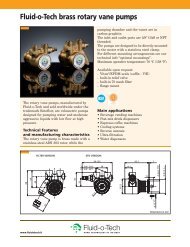
Section 3HOW IT WORKS—PUMPThe Wilden diaphragm pump is an air-operated, positive displacement, self-priming pump. These drawings show flow patternthrough the pump upon its initial stroke. It is assumed the pump has no fluid in it prior to its initial stroke.FIGURE 1 The air valve directs pressurizedair to the back side of diaphragm A. Thecompressed air is applied directly to theliquid column separated by elastomericdiaphragms. The diaphragm acts asa separation membrane between thecompressed air and liquid, balancing theload and removing mechanical stressfrom the diaphragm. The compressedair moves the diaphragm away fromthe center of the pump. The oppositediaphragm is pulled in by the shaftconnected to the pressurized diaphragm.Diaphragm B is on its suction stroke; airbehind the diaphragm has been forcedout to atmosphere through the exhaustport of the pump. The movement ofdiaphragm B toward the center of thepump creates a vacuum within chamber B.Atmospheric pressure forces fluid intothe inlet manifold forcing the inlet valveball off its seat. Liquid is free to movepast the inlet valve ball and fill the liquidchamber (see shaded area).FIGURE 2 When the pressurized diaphragm,diaphragm A, reaches the limit of its dischargestroke, the air valve redirects pressurizedair to the back side of diaphragm B. Thepressurized air forces diaphragm B awayfrom the center while pulling diaphragm Ato the center. Diaphragm B is now on itsdischarge stroke. Diaphragm B forces theinlet valve ball onto its seat due to thehydraulic forces developed in the liquidchamber and manifold of the pump. Thesesame hydraulic forces lift the dischargevalve ball off its seat, while the oppositedischarge valve ball is forced onto its seat,forcing fluid to flow through the pumpdischarge. The movement of diaphragm Atoward the center of the pump creates avacuum within liquid chamber A. Atmosphericpressure forces fluid into the inletmanifold of the pump. The inlet valve ballis forced off its seat allowing the fluid beingpumped to fill the liquid chamber.FIGURE 3 At completion of the stroke,the air valve again redirects air to theback side of diaphragm A, which startsdiaphragm B on its exhaust stroke. Asthe pump reaches its original startingpoint, each diaphragm has gone throughone exhaust and one discharge stroke.This constitutes one complete pumpingcycle. The pump may take several cyclesto completely prime depending on theconditions of the application.HOW IT WORKS—AIR DISTRIBUTION SYSTEMThe Pro-Flo ® patented air distribution system incorporates twomoving parts: the air valve spool and the pilot spool. The heart ofthe system is the air valve spool and air valve. This valve designincorporates an unbalanced spool. The smaller end of the spoolis pressurized continuously, while the large end is alternatelypressurized then exhausted to move the spool. The spool directspressurized air to one air chamber while exhausting the other.The air causes the main shaft/diaphragm assembly to shift toone side — discharging liquid on that side and pulling liquid inon the other side. When the shaft reaches the end of its stroke,the inner piston actuates the pilot spool, which pressurizes andexhausts the large end of the air valve spool. The repositioningof the air valve spool routes the air to the other air chamber.WIL-10110-E-02 8/06 3 WILDEN PUMP & ENGINEERING, LLC
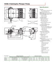
Section 4DIMENSIONAL DRAWINGS<strong>P15</strong> MetalR76 mm(3") FNPTLIQUID INLETALM76 mm(3") FNPTLIQUID DISCHARGENBC76 mm(3") FNPTLIQUID INLETPD19 mm(3/4") FNPTAIR INLETUEVJWXALUMINUM BASE SCREENF - 316 S.S., C.I., ALLOY CG - ALUM.KY25 mm (1")FNPT AIREXHAUSTHDIMENSIONSITEM METRIC (mm) STANDARD (inch)A 505 19.9B 58 2.3C 762 30.0D 823 32.4E 391 15.4F 71 2.8G 69 2.7H 406 16.0J 165 6.5K 523 20.6L 361 14.2M 305 12.0N 259 10.2P 282 11.1R 15 0.6S 71 2.8T 66 2.6U 305 12.0V 43 1.7W 305 12.0X 478 18.8Y 15 0.6SFOOTED BASE FOR STAINLESSSTEEL & ALLOY C MODELST76 mm(3") FNPTLIQUID INLET<strong>P15</strong> Metal Saniflo FDA76 mm (3")TRI-CLAMPLIQUID DISCHARGEFDIMENSIONSITEM METRIC (mm) STANDARD (inch)A 521 20.5B 71 2.8C 767 30.2D 810 31.9E 391 15.4F 89 3.5G 216 8.5H 406 16.0J 523 20.6K 356 14.0L 305 12.0M 257 10.1N 279 11.0P 15 0.6KLABCD76 mm (3")TRI-CLAMPLIQUID INLET19 mm (3/4")NPT FEMALEAIR INLETM N GEJ25 mm (1")FNPT AIREXHAUSTHPWILDEN PUMP & ENGINEERING, LLC 4 WIL-10110-E-02 8/06
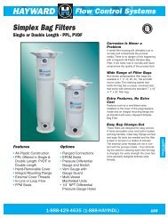
DIMENSIONAL DRAWINGS<strong>PV15</strong> MetalR76 mm (3") FNPTLIQUID INLETSALMNFOOTED BASE FOR STAINLESSSTEEL & ALLOY C MODELS19 mm(3/4")FNPTAIRINLETBPCDE76 mm (3")FNPT LIQUIDDISCHARGEUVJWXALUMINUM BASE SCREEN76 mm (3") FNPTLIQUID INLETTKF - 316 S.S., C.I., ALLOY CG - ALUM.25 mm (1")FNPT AIREXHAUSTH76 mm (3") FNPTLIQUID INLETYDIMENSIONSITEM METRIC (mm) STANDARD (inch)A 505 19.9B 58 2.3C 386 15.2D 762 30.0E 823 32.4F 71 2.8G 84 3.3H 389 15.3J 216 8.5K 406 16.0L 363 14.3M 307 12.1N 257 10.1P 282 11.1R 15 0.6S 71 2.8T 66 2.6U 305 12.0V 43 1.7W 305 12.0X 478 18.8Y 15 DIA. .6 DIA.<strong>PV15</strong> Metal Saniflo FDA76 mm (3")TRI-CLAMPLIQUID DISCHARGEFDIMENSIONSITEM METRIC (mm) STANDARD (inch)A 521 20.5B 71 2.8C 396 15.6D 767 30.2E 810 31.9F 89 3.5G 216 8.5H 406 16.0J 424 16.7K 356 14.0L 305 12.0M 257 10.1N 279 11.0P 15 0.6FAKL19 mm(3/4")FNPTAIR INLETMBNCDEGJ25 mm (1")FNPT AIREXHAUSTH76 mm (3")TRI-CLAMPLIQUID INLETPWIL-10110-E-02 8/06 5 WILDEN PUMP & ENGINEERING, LLC
Section 5APERFORMANCE5 performance Curves<strong>P15</strong> METALRUBBER-FITTEDHeight .................................823 mm (32.4")Width ..................................505 mm (19.9")Depth ..................................523 mm (20.6")Est. Ship Weight ...Aluminum 60 kg (132 lbs)316 Stainless Steel 90 kg (198 lbs)Cast Iron 98 kg (216 lbs)Alloy C 112 kg (246 lbs)Air Inlet ................................... 19 mm (3⁄4")Inlet ............................................76 mm (3")Outlet .........................................76 mm (3")Suction Lift ......................6.7 m Dry (22.1')9.3 m Wet (30.6')Displacement/Stroke ......5.61 l (1.48 gal.) 1Max. Flow Rate ........... 920 lpm (243 gpm)Max. Size Solids ...................9.5 mm (3⁄8")1Displacement per stroke was calculatedat 4.8 bar (70 psig) air inlet pressureagainst a 2.1 bar (30 psig) head pressure.Example: To pump 227 lpm (60 gpm)against a discharge head of 3.7 bar(54 psig) requires 4.1 bar (60 psig) and61 Nm 3 /h (36 scfm) air consumption.Caution: Do not exceed 8.6 bar (125 psig)air supply pressure.Flow rates indicated on chart were determined by pumping water.For optimum life and performance, pumps should be specified so that daily operationparameters will fall in the center of the pump performance curve.<strong>P15</strong> METALTPE-FITTEDHeight .................................823 mm (32.4")Width ..................................505 mm (19.9")Depth ..................................523 mm (20.6")Est. Ship Weight ...Aluminum 60 kg (132 lbs)316 Stainless Steel 90 kg (198 lbs)Cast Iron 98 kg (216 lbs)Alloy C 112 kg (246 lbs)Air Inlet ................................... 19 mm (3⁄4")Inlet ............................................76 mm (3")Outlet .........................................76 mm (3")Suction Lift ..................... 6.9 m Dry (22.7')9.2 m Wet (29.5')Displacement/Stroke ........5.7 l (1.49 gal.) 1Max. Flow Rate ............878 lpm (232 gpm)Max. Size Solids ...................9.5 mm (3⁄8")1Displacement per stroke was calculatedat 4.8 bar (70 psig) air inlet pressureagainst a 2.1 bar (30 psig) head pressure.Example: To pump 227 lpm (60 gpm)against a discharge pressure head of 3.4bar (50 psig) requires 4.1 bar (60 psig) and58 Nm 3 /h (34 scfm) air consumption.Caution: Do not exceed 8.6 bar (125 psig)air supply pressure.Flow rates indicated on chart were determined by pumping water.For optimum life and performance, pumps should be specified so that daily operationparameters will fall in the center of the pump performance curve.WILDEN PUMP & ENGINEERING, LLC 6 WIL-10110-E-02 8/06
PERFORMANCE<strong>P15</strong> METALPTFE-FITTEDHeight .................................823 mm (32.4")Width ..................................505 mm (19.9")Depth ..................................523 mm (20.6")Est. Ship Weight ...Aluminum 60 kg (132 lbs)316 Stainless Steel 90 kg (198 lbs)Cast Iron 98 kg (216 lbs)Alloy C 112 kg (246 lbs)Air Inlet ................................... 19 mm (3⁄4")Inlet ............................................76 mm (3")Outlet .........................................76 mm (3")Suction Lift ......................4.8 m Dry (15.9')9.0 m Wet (29.5')Displacement/Stroke ....... 3.6 l (0.95 gal.) 1Max. Flow Rate ............708 lpm (187 gpm)Max. Size Solids ...................9.5 mm (3⁄8")1Displacement per stroke was calculatedat 4.8 bar (70 psig) air inlet pressureagainst a 2.1 bar (30 psig) head pressure.Example: To pump 227 lpm (60 gpm)against a discharge pressure head of 2.9bar (42 psig) requires 4.1 bar (60 psig) and80 Nm 3 /h (47 scfm) air consumption.Caution: Do not exceed 8.6 bar (125 psig)air supply pressure.Flow rates indicated on chart were determined by pumping water.For optimum life and performance, pumps should be specified so that daily operationparameters will fall in the center of the pump performance curve.<strong>P15</strong> METALULTRA-FLEX-FITTEDHeight .................................823 mm (32.4")Width ..................................505 mm (19.9")Depth ..................................523 mm (20.6")Est. Ship Weight ...Aluminum 60 kg (132 lbs)316 Stainless Steel 80 kg (198 lbs)Cast Iron 98 kg (216 lbs)Alloy C 112 kg (246 lbs)Air Inlet ................................... 19 mm (3⁄4")Inlet ............................................76 mm (3")Outlet .........................................76 mm (3")Suction Lift ......................8.0 m Dry (26.1')9.2 m Wet (30.1')Displacement/Stroke ......4.62 l (1.22 gal.) 1Max. Flow Rate ............825 lpm (218 gpm)Max. Size Solids ...................9.5 mm (3⁄8")1Displacement per stroke was calculatedat 4.8 bar (70 psig) air inlet pressureagainst a 2.1 bar (30 psig) head pressure.Example: To pump 227 lpm (60 gpm)against a discharge pressure head of 3.3bar (48 psig) requires 4.1 bar (60 psig) and68 Nm 3 /h (40 scfm) air consumption.Caution: Do not exceed 8.6 bar (125 psig)air supply pressure.Flow rates indicated on chart were determined by pumping water.For optimum life and performance, pumps should be specified so that daily operationparameters will fall in the center of the pump performance curve.WIL-10110-E-02 8/06 7 WILDEN PUMP & ENGINEERING, LLC
15 performance Curves<strong>PV15</strong> METALRUBBER-FITTEDPERFORMANCEHeight .................................823 mm (32.4")Width ..................................505 mm (19.9")Depth ..................................406 mm (16.0")Est. Ship Weight ...Aluminum 55 kg (121 lbs)316 Stainless Steel 85 kg (187 lbs)Cast Iron 93 kg (205 lbs)Alloy C 107 kg (235 lbs)Air Inlet ................................... 19 mm (3⁄4")Inlet ............................................76 mm (3")Outlet .........................................76 mm (3")Suction Lift ......................6.6 m Dry (21.6')9.3 m Wet (30.6')Displacement/Stroke ......5.53 l (1.46 gal.) 1Max. Flow Rate ........... 909 lpm (240 gpm)Max. Size Solids ...................9.5 mm (3⁄8")1Displacement per stroke was calculatedat 4.8 bar (70 psig) air inlet pressureagainst a 2.1 bar (30 psig) head pressure.Example: To pump 454 lpm (120 gpm)against a discharge head of 3.6 bar(52 psig) requires 5.5 bar (80 psig) and170 Nm 3 /h (100 scfm) air consumption.Caution: Do not exceed 8.6 bar (125 psig)air supply pressure.Flow rates indicated on chart were determined by pumping water.For optimum life and performance, pumps should be specified so that daily operationparameters will fall in the center of the pump performance curve.<strong>PV15</strong> METALTPE-FITTEDHeight .................................823 mm (32.4")Width ..................................505 mm (19.9")Depth ..................................406 mm (16.0")Est. Ship Weight ...Aluminum 55 kg (121 lbs)316 Stainless Steel 85 kg (187 lbs)Cast Iron 93 kg (205 lbs)Alloy C 107 kg (235 lbs)Air Inlet ................................... 19 mm (3⁄4")Inlet ............................................76 mm (3")Outlet .........................................76 mm (3")Suction Lift ......................7.6 m Dry (25.0')9.5 m Wet (31.2')Displacement/Stroke ...... 5.72 l (1.51 gal.) 1Max. Flow Rate ........... 906 lpm (239 gpm)Max. Size Solids ...................9.5 mm (3⁄8")1Displacement per stroke was calculatedat 4.8 bar (70 psig) air inlet pressureagainst a 2.1 bar (30 psig) head pressure.Example: To pump 254 lpm (120 gpm)against a discharge pressure head of2.6 bar (38 psig) requires 4.1 bar (60psig) and 136 Nm 3 /h (80 scfm) airconsumption.Caution: Do not exceed 8.6 bar (125 psig)air supply pressure.Flow rates indicated on chart were determined by pumping water.For optimum life and performance, pumps should be specified so that daily operationparameters will fall in the center of the pump performance curve.WILDEN PUMP & ENGINEERING, LLC 8 WIL-10110-E-02 8/06
PERFORMANCE<strong>PV15</strong> METALPTFE-FITTEDHeight .................................823 mm (32.4")Width ..................................505 mm (19.9")Depth ..................................406 mm (16.0")Est. Ship Weight ...Aluminum 55 kg (121 lbs)316 Stainless Steel 85 kg (187 lbs)Cast Iron 93 kg (205 lbs)Alloy C 107 kg (235 lbs)Air Inlet ................................... 19 mm (3⁄4")Inlet ............................................76 mm (3")Outlet .........................................76 mm (3")Suction Lift ......................5.0 m Dry (16.5')9.5 m Wet (31.2')Displacement/Stroke ..... 3.48 l (0.92 gal.) 1Max. Flow Rate ............704 lpm (186 gpm)Max. Size Solids ...................9.5 mm (3⁄8")1Displacement per stroke was calculatedat 4.8 bar (70 psig) air inlet pressureagainst a 2.1 bar (30 psig) head pressure.Example: To pump 151 lpm (40 gpm)against a discharge pressure head of3.5 bar (51 psig) requires 4.1 bar (60 psig)and 68 Nm 3 /h (40 scfm) air consumption.Caution: Do not exceed 8.6 bar (125 psig)air supply pressure.Flow rates indicated on chart were determined by pumping water.For optimum life and performance, pumps should be specified so that daily operationparameters will fall in the center of the pump performance curve.<strong>PV15</strong> METALULTRA-FLEX-FITTEDHeight .................................823 mm (32.4")Width ..................................505 mm (19.9")Depth ..................................406 mm (16.0")Est. Ship Weight ...Aluminum 55 kg (121 lbs)316 Stainless Steel 85 kg (187 lbs)Cast Iron 93 kg (205 lbs)Alloy C 107 kg (235 lbs)Air Inlet ................................... 19 mm (3⁄4")Inlet ............................................76 mm (3")Outlet .........................................76 mm (3")Suction Lift ......................6.1 m Dry (20.0')9.5 m Wet (31.2')Displacement/Stroke ......4.69 l (1.24 gal.) 1Max. Flow Rate ........... 854 lpm (226 gpm)Max. Size Solids ...................9.5 mm (3⁄8")1Displacement per stroke was calculatedat 4.8 bar (70 psig) air inlet pressureagainst a 2.1 bar (30 psig) head pressure.Example: To pump 303 lpm (80 gpm)against a discharge pressure head of4.3 bar (62 psig) requires 5.5 bar(80 psig) and 136 Nm 3 /h (80 scfm) airconsumption.Caution: Do not exceed 8.6 bar (125 psig)air supply pressure.Flow rates indicated on chart were determined by pumping water.For optimum life and performance, pumps should be specified so that daily operationparameters will fall in the center of the pump performance curve.WIL-10110-E-02 8/06 9 WILDEN PUMP & ENGINEERING, LLC
Section 5B<strong>P15</strong> METAL SUCTIONLIFT CAPABILITYSUCTION LIFT CURVES<strong>PV15</strong> METAL SUCTIONLIFT CAPABILITYSuction lift curves are calibrated for pumps operatingat 305 m (1,000') above sea level. This chart is meantto be a guide only. There are many variables whichcan affect your pump’s operating characteristics. Thenumber of intake and discharge elbows, viscosity ofpumping fluid, elevation (atmospheric pressure) andpipe friction loss all affect the amount of suction liftyour pump will attain.WILDEN PUMP & ENGINEERING, LLC 10 WIL-10110-E-02 8/06
Section 6SUGGESTED INSTALLATIONWilden pumps are designed to meet the performancerequirements of even the most demanding pumpingapplications. They have been designed and manufacturedto the highest standards and are available in a variety ofliquid path materials to meet your chemical resistanceneeds. Refer to the performance section of this manual foran in-depth analysis of the performance characteristics ofyour pump. Wilden offers the widest variety of elastomeroptions in the industry to satisfy temperature, chemicalcompatibility, abrasion resistance and flex concerns.The suction pipe size should be at least the equivalent orlarger than the diameter size of the suction inlet on yourWilden pump. The suction hose must be non-collapsible,reinforced type as these pumps are capable of pulling a highvacuum. Discharge piping should also be the equivalentor larger than the diameter of the pump discharge whichwill help reduce friction losses. It is critical that all fittingsand connections are airtight or a reduction or loss of pumpsuction capability will result.INSTALLATION: Months of careful planning, study,and selection efforts can result in unsatisfactory pumpperformance if installation details are left to chance.Premature failure and long term dissatisfaction can beavoided if reasonable care is exercised throughout theinstallation process.LOCATION: Noise, safety, and other logistical factors usuallydictate where equipment will be situated on the productionfloor. Multiple installations with conflicting requirementscan result in congestion of utility areas, leaving few choicesfor additional pumps.Within the framework of these and other existing conditions,every pump should be located in such a way that six keyfactors are balanced against each other to maximumadvantage.ACCESS: First of all, the location should be accessible. Ifit’s easy to reach the pump, maintenance personnel willhave an easier time carrying out routine inspections andadjustments. Should major repairs become necessary, easeof access can play a key role in speeding the repair processand reducing total downtime.AIR SUPPLY: Every pump location should have an air linelarge enough to supply the volume of air necessary toachieve the desired pumping rate. Use air pressure up toa maximum of 8.6 bar (125 psig) depending on pumpingrequirements.For best results, the pumps should use a 5μ (micron) airfilter, needle valve and regulator. The use of an air filterbefore the pump will ensure that the majority of any pipelinecontaminants will be eliminated.SOLENOID OPERATION: When operation is controlled by asolenoid valve in the air line, three-way valves should beused. This valve allows trapped air between the valve andthe pump to bleed off which improves pump performance.Pumping volume can be estimated by counting the numberof strokes per minute and then multiplying the figure by thedisplacement per stroke.MUFFLER: Sound levels are reduced below OSHAspecifications using the standard Wilden muffler. Othermufflers can be used to further reduce sound levels, butthey usually reduce pump performance.ELEVATION: Selecting a site that is well within the pump’sdynamic lift capability will assure that loss-of-prime issues willbe eliminated. In addition, pump efficiency can be adverselyaffected if proper attention is not given to site location.PIPING: Final determination of the pump site should not bemade until the piping challenges of each possible locationhave been evaluated. The impact of current and futureinstallations should be considered ahead of time to makesure that inadvertent restrictions are not created for anyremaining sites.The best choice possible will be a site involving the shortestand straightest hook-up of suction and discharge piping.Unnecessary elbows, bends, and fittings should be avoided.Pipe sizes should be selected to keep friction losses withinpractical limits. All piping should be supported independentlyof the pump. In addition, the piping should be aligned toavoid placing stress on the pump fittings.Flexible hose can be installed to aid in absorbing the forcescreated by the natural reciprocating action of the pump. If thepump is to be bolted down to a solid location, a mountingpad placed between the pump and the foundation will assistin minimizing pump vibration. Flexible connections betweenthe pump and rigid piping will also assist in minimizingpump vibration. If quick-closing valves are installed at anypoint in the discharge system, or if pulsation within a systembecomes a problem, a surge suppressor (SD Equalizer ® )should be installed to protect the pump, piping and gaugesfrom surges and water hammer.If the pump is to be used in a self-priming application, makesure that all connections are airtight and that the suction lift iswithin the model’s ability. Note: Materials of construction andelastomer material have an effect on suction lift parameters.Please refer to the performance section for specifics.When pumps are installed in applications involving floodedsuction or suction head pressures, a gate valve should beinstalled in the suction line to permit closing of the line forpump service.<strong>Pumps</strong> in service with a positive suction head are most efficientwhen inlet pressure is limited to 0.5–0.7 bar (7–10 psig).Premature diaphragm failure may occur if positive suctionis 0.7 bar (10 psig) and higher.SUBMERSIBLE APPLICATIONS: Pro-Flo V pumps can beused for submersible applications, when using the Pro-FloV submersible option. Turbo-Flo pumps can also beused for submersible applications.NOTE: Pro-Flo ® and Accu-Flo pumps are not submersible.ALL WILDEN PUMPS ARE CAPABLE OF PASSING SOLIDS.A STRAINER SHOULD BE USED ON THE PUMP INTAKE TOENSURE THAT THE PUMP'S RATED SOLIDS CAPACITY ISNOT EXCEEDED.CAUTION: DO NOT EXCEED 8.6 BAR (125 PSIG) AIRSUPPLY PRESSURE.WIL-10110-E-02 8/06 11 WILDEN PUMP & ENGINEERING, LLC
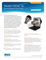
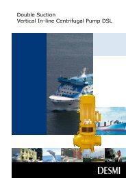
SUGGESTED INSTALLATIONThis illustration is a genericrepresentation of an air-operateddouble-diaphragm pump.NOTE: In the event of a power failure, the shut off valveshould be closed, if the restarting of the pump is notdesirable once power is regained.AIR OPERATED PUMPS: To stop the pump fromoperating in an emergency situation, simply close theshut off valve (user supplied) installed in the air supplyline. A properly functioning valve will stop the air supplyto the pump, therefore stopping output. This shut offvalve should be located far enough away from thepumping equipment such that it can be reached safelyin an emergency situation.WILDEN PUMP & ENGINEERING, LLC 12 WIL-10110-E-02 8/06
SUGGESTED OPERATION & MAINTENANCEOPERATION: The <strong>P15</strong> and <strong>PV15</strong> are pre-lubricated, anddo not require in-line lubrication. Additional lubricationwill not damage the pump, however if the pump isheavily lubricated by an external source, the pump’sinternal lubrication may be washed away. If the pumpis then moved to a non-lubricated location, it may needto be disassembled and re-lubricated as described inthe ASSEMBLY/DISASSEMBLY INSTRUCTIONS.Pump discharge rate can be controlled by limitingthe volume and/or pressure of the air supply to thepump. An air regulator is used to regulate air pressure.A needle valve is used to regulate volume. Pumpdischarge rate can also be controlled by throttlingthe pump discharge by partially closing a valve inthe discharge line of the pump. This action increasesfriction loss which reduces flow rate. (See Section 5.)This is useful when the need exists to control the pumpfrom a remote location. When the pump dischargepressure equals or exceeds the air supply pressure,the pump will stop; no bypass or pressure relief valveis needed, and pump damage will not occur. Thepump has reached a “deadhead” situation and canbe restarted by reducing the fluid discharge pressureor increasing the air inlet pressure. The Wilden <strong>P15</strong>and <strong>PV15</strong> pumps run solely on compressed air anddoes not generate heat, therefore your process fluidtemperature will not be affected.MAINTENANCE AND INSPECTIONS: Since eachapplication is unique, maintenance schedules maybe different for every pump. Frequency of use, linepressure, viscosity and abrasiveness of process fluidall affect the parts life of a Wilden pump. Periodicinspections have been found to offer the bestmeans for preventing unscheduled pump downtime.Personnel familiar with the pump’s construction andservice should be informed of any abnormalities thatare detected during operation.RECORDS: When service is required, a record shouldbe made of all necessary repairs and replacements.Over a period of time, such records can become avaluable tool for predicting and preventing futuremaintenance problems and unscheduled downtime. Inaddition, accurate records make it possible to identifypumps that are poorly suited to their applications.TROUBLESHOOTINGPump will not run or runs slowly.1. Ensure that the air inlet pressure is at least 0.4 bar(5 psig) above startup pressure and that the differentialpressure (the difference between air inlet and liquiddischarge pressures) is not less than 0.7 bar (10 psig).2. Check air inlet filter for debris (see recommendedinstallation).3. Check for extreme air leakage (blow by) whichwould indicate worn seals/bores in the air valve,pilot spool, main shaft.4. Disassemble pump and check for obstructionsin the air passageways or objects which wouldobstruct the movement of internal parts.5. Check for sticking ball check valves. If materialbeing pumped is not compatible with pumpelastomers, swelling may occur. Replace ballcheck valves and seals with proper elastomers.Also, as the check valve balls wear out, theybecome smaller and can become stuck in theseats. In this case, replace balls and seats.6. Check for broken inner piston which will cause theair valve spool to be unable to shift.7. Remove plug from pilot spool exhaust.Pump runs but little or no product flows.1. Check for pump cavitation; slow pump speeddown to allow thick material to flow into liquidchambers.2. Verify that vacuum required to lift liquid is notgreater than the vapor pressure of the materialbeing pumped (cavitation).3. Check for sticking ball check valves. If material beingpumped is not compatible with pump elastomers,swelling may occur. Replace ball check valves andseats with proper elastomers. Also, as the checkvalve balls wear out, they become smaller and canbecome stuck in the seats. In this case, replace ballsand seats.Pump air valve freezes.1. Check for excessive moisture in compressedair. Either install a dryer or hot air generator forcompressed air. Alternatively, a coalescing filter maybe used to remove the water from the compressedair in some applications.Air bubbles in pump discharge.1. Check for ruptured diaphragm.2. Check tightness of outer pistons (refer to Section 7).3. Check tightness of fasteners and integrity ofo-rings and seals, especially at intake manifold.4. Ensure pipe connections are airtight.Product comes out air exhaust.1. Check for diaphragm rupture.2. Check tightness of outer pistons to shaft.WIL-10110-E-02 8/06 13 WILDEN PUMP & ENGINEERING, LLC
ection 7 Assembly / disassemblySection 7PUMP DISASSEMBLYTools Required :• 11/16" Wrench• 3/4" Wrench• Adjustable Wrench• Vise equipped w/soft jaws (such asplywood, plasticor other suitablematerial)CAUTION: Before any maintenance or repair is attempted, the compressed air lineto the pump should be disconnected and all air pressure allowed to bleed from thepump. Disconnect all intake, discharge, and air lines. Drain the pump by turning itupside down and allowing any fluid to flow into a suitable container. Be aware ofany hazardous effects of contact with your process fluid.NOTE: The model photographed for these instructions incorporates rubberdiaphragms, balls, and seats. Models with PTFE diaphragms, balls and seats arethe same except where noted.Step 1.Before starting disassembly, marka line from each liquid chamber toits corresponding air chamber. Thisline will assist in proper alignmentduring reassembly.Step 2Utilizing a 11/16" wrench, removethe two small clamp bands thatfasten the discharge manifold tothe liquid chambers.Step 3Remove the discharge manifold toexpose the valve balls and seats.Inspect ball cage area of manifoldfor excessive wear or damage.WILDEN PUMP & ENGINEERING, LLC 14 WIL-10110-E-02 8/06
PUMP DISASSEMBLYStep 4Step 5Step 6Remove the discharge valve ballsand seats from the liquid chambersand inspect for nicks, chemicalattack or abrasive wear. Replaceworn parts with genuine Wildenparts for reliable performance.Turn pump upside down andremove the two small clamp bandswhich fasten the intake manifold tothe liquid chambers.Lift intake manifold to expose intakevalve balls and seats. Inspect ballcage area of liquid chamber forexcessive wear or damage.Step 7Remove one set of large clampbands which secure one liquidchamber to the center section usingtwo 3/4" wrenches.Step 8Lift liquid chamber away fromcenter section to expose diaphragmand outer piston.Step 9Using an adjustable wrench, or byrotating the diaphragm by hand,remove the diaphragm assembly.WIL-10110-E-02 8/06 15 WILDEN PUMP & ENGINEERING, LLC
PUMP DISASSEMBLYStep 9AStep 9BStep 10Due to varying torque values, oneof the following two situationsmay occur: 1) The outer piston,diaphragm and inner piston remainattached to the shaft and the entireassembly can be removed from thecenter section.2) The outer piston, diaphragm andinner piston separate from the shaftwhich remains connected to theopposite side diaphragm assembly(Figure 9B). Repeat disassemblyinstructions for the opposite liquidchamber. Inspect diaphragmassembly and shaft for signs ofwear or chemical attack. Replaceall worn parts with genuine Wildenparts for reliable performance.To remove diaphragm assemblyfrom shaft, secure shaft with softjaws (a vise fitted with plywood,plastic, or other suitable material)to ensure shaft is not nicked,scratched or gouged. Usingan adjustable wrench, removediaphragm assembly from shaft.WILDEN PUMP & ENGINEERING, LLC 16 WIL-10110-E-02 8/06
AIR VALVE / CENTER SECTION DISASSEMBLYTools Required :Pro-Flo ®• 3/8" Hex Head Wrench• 1/4" Hex Head Wrench• Snap Ring Pliers• O-Ring PickPro-Flo V• 3/16" Hex Head Wrench• 1/4" Hex Head Wrench• Snap Ring Pliers• O-Ring PickCAUTION: Before any maintenance or repair is attempted, the compressed air lineto the pump should be disconnected and all air pressure allowed to bleed from thepump. Disconnect all intake, discharge, and air lines. Drain the pump by turning itupside down and allowing any fluid to flow into a suitable container. Be aware ofhazardous effects of contact with your process fluid.The Wilden <strong>P15</strong> and <strong>PV15</strong> metal pumps utilize a revolutionary Pro-Flo ® airdistribution system. Proprietary composite seals reduce the co efficient of frictionand allow lube-free operation. The Pro-Flo ® air distribution system is designed toperform in on/off, non-freezing, non-stalling, tough duty applications.Step 1Loosen the air valve bolts utilizing a3/8" hex head wrench.Step 2Remove muffler plate and air valvebolts from air valve assemblyexposing muffler gasket forinspection. Replace if necessary.Step 3Lift away air valve assemblyand remove air valve gasket forinspection. Replace if necessary.WIL-10110-E-02 8/06 17 WILDEN PUMP & ENGINEERING, LLC
AIR VALVE / CENTER SECTION DISASSEMBLYStep 4Remove air valve end cap to exposeair valve spool by simply lifting upon end cap once air valve bolts areremoved.Step 5Remove air valve spool from air valvebody by threading one air valve bolt intothe end of the spool and gently slidingthe spool out of the air valve body.Inspect seals for signs of wear andreplace entire assembly if necessary.Use caution when handling air valvespool to prevent damaging seals.NOTE: Seals should not be removedfrom assembly. Seals are not soldseparately.Step 6Remove pilot spool retaining snapring on both sides of center sectionwith snap ring pliers.Step 9Step 7Remove air chamber bolts with1/4" hex head wrench.Step 8Remove pilot spool bushing fromcenter block.With o-ring pick, gently remove theo-ring from the opposite side of thenotched end of the spool. Gentlyremove the pilot spool from sleeveand inspect for nicks or gouges andother signs of wear. replace pilot sleeveassembly or outer sleeve o-rings ifnecessary. During re-assembly neverinsert the pilot spool into the sleevewith the “notched" end side first, thisend incorporates the urethane o-ringand will be damaged as it slides overthe ports cut in the sleeve.NOTE: Seals should not beremoved from pilot spool. Sealsare not sold separately.WILDEN PUMP & ENGINEERING, LLC 18 WIL-10110-E-02 8/06
AIR VALVE / CENTER SECTION DISASSEMBLYStep 10Check center block seals for signsof wear. If necessary, remove shaftseals with o-ring pick and replace.SUBMERSIBLE PRO-FLO V Non-SubmersibleSubmersibleStep 1Install a 6 mm (1/4”) NPT pipe plug(00-7010-08) into the pilot spoolbleed port located at the front of thecenter block.Step 2Next, install an optional submersible air valve gasket(04-2621-52). The submersible air valve gasket canbe purchased as a spare part or included with thepurchase of a new Pro-Flo V pump.WIL-10110-E-02 8/06 19 WILDEN PUMP & ENGINEERING, LLC
REASSEMBLY HINTS & TIPSASSEMBLY:Upon performing applicable maintenance to the airdistribution system, the pump can now be reassembled.Please refer to the disassembly instructions for photosand parts placement. To reassemble the pump, followthe disassembly instructions in reverse order. The airdistribution system needs to be assembled first, thenthe diaphragms and finally the wetted path. Please findthe applicable torque specifications on this page. Thefollowing tips will assist in the assembly process.• Lubricate air valve bore, center section shaft andpilot spool bore with NLGI grade 2 white EP greaseor equivalent.• Clean the inside of the center section shaft bushing toensure no damage is done to new shaft seals.• A small amount NLGI grade 2 white EP grease canbe applied to the muffler and air valve gaskets tolocate gaskets during assembly.• Make sure that the exhaust port on the muffler plateis centered between the two exhaust ports on thecenter section.• Stainless bolts should be lubed to reduce thepossibility of seizing during tightening.• Use a mallet to tamp lightly on the large clampbands to seat the diaphragm before tightening.PRO-FLO ® MAXIMUM TORQUE SPECIFICATIONSDescription of PartAir ValveAir Chamber/Center BlockInner Piston RingOuter Pistons, Rubber & PTFEOuter Pistons, Ultra-FlexSmall Clamp BandsLarge Clamp Bands (Rubber-Fitted)Large Clamp Bands (PTFE-Fitted)Torque8.5 N•m (75 in-lbs)47.5 N•m (35 ft-lbs)19.0 N•m (14 ft-lbs)135.6 N•m (100 ft-lbs)135.6 N•m (100 ft-lbs)15.5 N•m (137 in-lbs)61.0 N•m (45 ft-lbs)61.0 N•m (45 ft-lbs)PRO-FLO V MAXIMUM TORQUE SPECIFICATIONSDescription of PartAir ValveAir Chamber/Center BlockInner Piston RingOuter Pistons, Rubber & PTFEOuter Pistons, Ultra-FlexSmall Clamp BandsLarge Clamp Bands (Rubber-Fitted)Large Clamp Bands (PTFE-Fitted)Figure ASHAFT SEALTorque13.6 N•m (120 in-lbs)27.1 N•m (20 ft-lbs)19.0 N•m (14 ft-lbs)135.6 N•m (100 ft-lbs)135.6 N•m (100 ft-lbs)15.5 N•m (137 in-lbs)61.0 N•m (45 ft-lbs)61.0 N•m (45 ft-lbs)SHAFT SEAL INSTALLATION:PRE-INSTALLATION• Once all of the old seals have been removed, theinside of the bushing should be cleaned to ensureno debris is left that may cause premature damageto the new seals.INSTALLATIONThe following tools can be used to aid in the installationof the new seals:Needle Nose PliersPhillips ScrewdriverElectrical Tape• Wrap electrical tape around each leg of the needle nosepliers (heat shrink tubing may also be used). This is doneto prevent damaging the inside surface of the new seal.• With a new seal in hand, place the two legs of the needlenose pliers inside the seal ring. (See Figure A.)• Open the pliers as wide as the seal diameter will allow,then with two fingers pull down on the top portion ofthe seal to form kidney bean shape. (See Figure B.)• Lightly clamp the pliers together to hold the seal intothe kidney shape. Be sure to pull the seal into as tightof a kidney shape as possible, this will allow the seal totravel down the bushing bore easier.• With the seal clamped in the pliers, insert the seal intothe bushing bore and position the bottom of the sealinto the correct groove. Once the bottom of the seal isseated in the groove, release the clamp pressure on thepliers. This will allow the seal to partially snap back to itsoriginal shape.• After the pliers are removed, you will notice a slightbump in the seal shape. Before the seal can be properlyresized, the bump in the seal should be removed asmuch as possible. This can be done with either thePhillips screwdriver or your finger. With either the sideof the screwdriver or your finger, apply light pressureto the peak of the bump. This pressure will cause thebump to be almost completely eliminated.• Lubricate the edge of the shaft with NLGI grade 2 whiteEP bearing grease.• Slowly insert the center shaft with a rotating motion.This will complete the resizing of the seal.• Perform these steps for the remaining seals.Figure BNEEDLE NOSEPLIERSSHAFT SEALTAPETAPEWILDEN PUMP & ENGINEERING, LLC 20 WIL-10110-E-02 8/06
WIL-10110-E-02 8/06 21 WILDEN PUMP & ENGINEERING, LLC
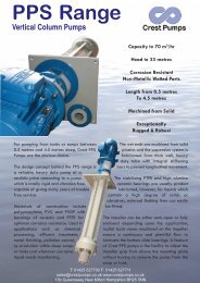
Section 8EXPLODED VIEW & PARTS LISTING<strong>P15</strong> METAL Rubber/TPE/Ultra-Flex-FittedEXPLODED VIEWBBALL CIRCLED PART IDENTIFIERS ARE INCLUDED IN REPAIR KITS (see section 9).WILDEN PUMP & ENGINEERING, LLC 22 WIL-10110-E-02 8/06
EXPLODED VIEW & PARTS LISTING<strong>P15</strong> METAL Rubber/TPE/Ultra-Flex-FittedPARTS LISTINGNo. Description Qty.<strong>P15</strong>/AAAAPP/N<strong>P15</strong>/WWAAPP/N<strong>P15</strong>/SSAAPP/N<strong>P15</strong>/HHAAPP/N<strong>P15</strong>/SSAAP/0070P/N1 Pro-Flo ® Air Valve Assembly 1 1 15-2010-20 15-2010-20 15-2010-20 15-2010-20 15-2010-202 O-Ring (-235), End Cap 1 71-1280-52 71-1280-52 71-1280-52 71-1280-52 71-1280-523 End Cap, Pro-Flo ® 1 15-2332-20 15-2332-20 15-2332-20 15-2332-20 15-2332-204 Screw, HHC, Air Valve (7/16-14 x 5 7/8") 6 15-6001-03 15-6001-03 15-6001-03 15-6001-03 15-6001-035 Muffler Plate, Pro-Flo ® 1 15-3181-20 15-3181-20 15-3181-20 15-3181-20 15-3181-206 Gasket, Muffler Plate 1 15-3505-52 15-3505-52 15-3505-52 15-3505-52 15-3505-527 Gasket, Air Valve 1 15-2615-52 15-2615-52 15-2615-52 15-2615-52 15-2615-528 Center Block Assembly 2 1 15-3110-01 15-3110-01 15-3110-01 15-3110-01 15-3110-019 Removable Pilot Sleeve Assembly 1 15-3880-99 15-3880-99 15-3880-99 15-3880-99 15-3880-9910 Pilot Spool Retaining O-ring 2 15-2650-49 15-2650-49 15-2650-49 15-2650-49 15-2650-4911 Center Block Shaft Seal 4 15-3210-55-225 15-3210-55-225 15-3210-55-225 15-3210-55-225 15-3210-55-22512 Gasket, Center Block, Pro-Flo ® 2 15-3525-52 15-3525-52 15-3525-52 15-3525-52 15-3525-5213 Air Chamber, Pro-Flo ® 2 15-3651-01 15-3651-01 15-3651-01 15-3651-01 15-3651-0114 Air Chamber Screw (3/8" - 16 x 1") 12 15-6130-08 15-6130-08 15-6130-08 15-6130-08 15-6130-0815 Retaining Ring 2 15-2651-03 15-2651-03 15-2651-03 15-2651-03 15-2651-0316 Shaft 1 15-3805-09 15-3805-09 15-3805-09 15-3805-09 15-3805-0917 Washer, Inner Piston Back-up 2 15-6850-08 15-6850-08 15-6850-08 15-6850-08 15-6850-0818 Piston, Inner 2 15-3700-01 15-3700-01 15-3700-01 15-3700-01 15-3700-01Piston, Inner, Ultra-Flex 2 15-3760-08 15-3760-08 15-3760-08 15-3760-08 N/A19 Outer Piston Bolt (3/8" - 16 x 1-1/8") 12 15-6130-08 15-6130-08 15-6130-08 15-6130-08 15-6130-0820 Washer, Flat 12 15-6740-08-50 15-6740-08-50 15-6740-08-50 15-6740-08-50 15-6740-08-5021 Diaphragm 2 * * * * 15-1010-5622 Piston, Outer 2 15-4550-01 15-4550-02 15-4550-03 15-4550-04 15-4550-03Piston, Outer, Ultra-Flex 2 15-4560-01 15-4560-02 15-4560-03 15-4560-04 N/A23 Valve Ball 4 * * * * 15-1080-5624 Valve Seat 4 * * * * 15-1120-5625 Liquid Chamber 2 15-5000-01 15-5000-02 15-5000-03 15-5000-04 15-5000-0326 Discharge Manifold 1 15-5020-01 15-5020-02 15-5020-03 15-5020-04 15-5020-03-7027 Inlet Housing for Footed Base 1 15-5080-01 15-5080-02 15-5080-03 15-5080-04 15-5080-03-7028 Large Clamp Band Assy. 2 15-7300-08 15-7300-08 15-7300-03 15-7300-03 15-7300-03-7029 Large Hex Bolt (1/2" - 13 x 3-1/2") 4 15-6120-08 15-6120-08 15-6120-03 15-6120-03 15-6120-0330 Large Hex Nut 3 (1/2" - 13) 4 15-6420-08 15-6420-08 15-6420-03 15-6420-03 15-6671-1031 Small Clamp Band Assy. 4 15-7100-08 15-7100-08 15-7100-03 15-7100-03 15-7100-03-7032 Small Hex Bolt (3/8" - 16 x 2-1/4" 3 ) 8 15-6050-08 15-6050-08 15-6050-03 15-6050-03 15-6050-0333 Small Hex Nut (3/8" - 16) 8 08-6450-08 08-6450-08 08-6450-03 08-6450-03 08-6671-10Muffler (not shown) 1 15-3510-99 15-3510-99 15-3510-99 15-3510-99 15-3510-99Washer, Flat 1/4" (not shown) 8 N/A N/A N/A N/A 08-6720-07-70Washer, Flat 5/16" (not shown) 4 N/A N/A N/A N/A 15-6720-07-70*Refer to corresponding elastomer chart in Section 9.1Air Valve Assembly includes items 2 and 3.2Center block assembly includes item 11.3P/N 15-6050-03 is 2" long.All boldface items are primary wear parts0030 Specialty Code = Screen Based0070 Specialty Code = Saniflo FDAScreen Base Assembly - /0030 Specialty CodeNo. Description Qty. /030 P/N27 Inlet Manifold 1 15-5080-01-3034 Screen Base 1 15-5620-0135 Suction Hook-up Cover 1 15-5660-0136 Hex Machine Screw (3/8"-16 x 7/8") 1 08-6140-0837 Hex Nut (3/8"-16) 2 08-6450-0838 Hex Machine Screws (3/8"-16 x 3") 2 08-6120-08WIL-10110-E-02 8/06 23 WILDEN PUMP & ENGINEERING, LLC
EXPLODED VIEW & PARTS LISTING<strong>P15</strong> METAL PTFE-FittedEXPLODED VIEWALL CIRCLED PART IDENTIFIERS ARE INCLUDED IN REPAIR KITS (see section 9).WILDEN PUMP & ENGINEERING, LLC 24 WIL-10110-E-02 8/06
EXPLODED VIEW & PARTS LISTING<strong>P15</strong> METAL PTFE-FittedPARTS LISTINGNo. Description Qty.<strong>P15</strong>/AAAAPP/N<strong>P15</strong>/WWAAPP/N<strong>P15</strong>/SSAAPP/N<strong>P15</strong>/HHAAPP/N<strong>P15</strong>/SSAAP/0070P/N1 Pro-Flo ® Air Valve Assembly 1 1 15-2010-20 15-2010-20 15-2010-20 15-2010-20 15-2010-202 O-Ring (-235), End Cap 1 71-1280-52 71-1280-52 71-1280-52 71-1280-52 71-1280-523 End Cap, Pro-Flo ® 1 15-2332-20 15-2332-20 15-2332-20 15-2332-20 15-2332-204 Screw, HHC, Air Valve (7/16"-14 x 5 7/8") 6 15-6001-03 15-6001-03 15-6001-03 15-6001-03 15-6001-035 Muffler Plate, Pro-Flo ® 1 15-3181-20 15-3181-20 15-3181-20 15-3181-20 15-3181-206 Gasket, Muffler Plate 1 15-3505-52 15-3505-52 15-3505-52 15-3505-52 15-3505-527 Gasket, Air Valve 1 15-2615-52 15-2615-52 15-2615-52 15-2615-52 15-2615-528 Center Block Assembly 2 1 15-3110-01 15-3110-01 15-3110-01 15-3110-01 15-3110-019 Removable Pilot Sleeve Assembly 1 15-3880-99 15-3880-99 15-3880-99 15-3880-99 15-3880-9910 Pilot Spool Retaining O-ring 2 15-2650-49 15-2650-49 15-2650-49 15-2650-49 15-2650-4911 Center Block Shaft Seal 4 15-3210-55-225 15-3210-55-225 15-3210-55-225 15-3210-55-225 15-3210-55-22512 Gasket, Center Block, Pro-Flo ® 2 15-3525-52 15-3525-52 15-3525-52 15-3525-52 15-3525-5213 Air Chamber, Pro-Flo ® 2 15-3651-01 15-3651-01 15-3651-01 15-3651-01 15-3651-0114 Air Chamber Screw (3/8" - 16 x 1") 12 15-6130-08 15-6130-08 15-6130-08 15-6130-08 15-6130-0815 Retaining Ring 2 15-2651-03 15-2651-03 15-2651-03 15-2651-03 15-2651-0316 Shaft 1 15-3805-09 15-3805-09 15-3805-09 15-3805-09 15-3805-0917 Piston, Inner 2 15-3750-01 15-3750-01 15-3750-01 15-3750-01 15-3750-0118 Back-up Diaphragm 2 15-1060-51 15-1060-51 15-1060-51 15-1060-51 15-1060-5119 Diaphragm 2 15-1010-55 15-1010-55 15-1010-55 15-1010-55 15-1010-5520 Piston, Outer 2 15-4600-03 15-4600-03 15-4600-03 15-4600-04 15-4600-0321 Valve Ball 4 15-1080-55 15-1080-55 15-1080-55 15-1080-55 15-1080-5522 Valve Seat 4 15-1121-01 15-1121-08 15-1121-03 15-1121-04 15-1121-0323 PTFE Valve Seat O-Ring 4 15-1200-55 15-1200-55 15-1200-55 15-1200-55 15-1200-5524 Liquid Chamber 2 15-5000-01 15-5000-02 15-5000-03 15-5000-04 15-5000-0325 Discharge Manifold 1 15-5020-01 15-5020-02 15-5020-03 15-5020-04 15-5020-03-7026 Inlet Manifold 1 15-5080-01 15-5080-02 15-5080-03 15-5080-04 15-5080-03-7027 Large Clamp Band Assy. 2 15-7300-03 15-7300-03 15-7300-03 15-7300-03 15-7300-03-7028 Large Hex Bolt (1/2" - 13 x 3-1/2") 4 15-6120-03 15-6120-03 15-6120-03 15-6120-03 15-6120-0329 Large Hex Nut 2 (1/2" - 13") 4 15-6420-03 15-6420-03 15-6420-03 15-6420-03 15-6671-1030 Small Clamp Band Assy. 4 15-7100-03 15-7100-03 15-7100-03 15-7100-03 15-7100-03-7031 Small Carriage Bolt (3/8" - 16 x 2") 8 15-6050-03 15-6050-03 15-6050-03 15-6050-03 15-6050-0332 Small Hex Nut (3/8" - 16") 8 08-6450-03 08-6450-03 08-6450-03 08-6450-03 08-6671-10Muffler (not shown) 1 15-3510-99 15-3510-99 15-3510-99 15-3510-99 15-3510-99Washer, Flat 1/4" (not shown) 8 N/A N/A N/A N/A 08-6720-07-70Washer, Flat 5/16" (not shown) 4 N/A N/A N/A N/A 15-6720-07-701Air Valve Assembly includes items 2 and 3.2Center Block Assembly includes item 11.0070 Specialty Code = Saniflo FDAAll boldface items are primary wear parts.WIL-10110-E-02 8/06 25 WILDEN PUMP & ENGINEERING, LLC
EXPLODED VIEW & PARTS LISTING<strong>PV15</strong> METAL Rubber/TPE/Ultra-Flex-FittedEXPLODED VIEWALL CIRCLED PART IDENTIFIERS ARE INCLUDED IN REPAIR KITS (see section 9).WILDEN PUMP & ENGINEERING, LLC 26 WIL-10110-E-02 8/06
EXPLODED VIEW & PARTS LISTING<strong>PV15</strong> METAL Rubber/TPE/Ultra-Flex-FittedPARTS LISTINGNo. Description Qty.<strong>PV15</strong>/AAAAAP/N<strong>PV15</strong>/WWAAAP/N<strong>PV15</strong>/SSAAAP/N<strong>PV15</strong>/SSSSSP/N<strong>PV15</strong>/SAAAA/0070P/N<strong>PV15</strong>/SSSSS/0070P/N1 Pro-Flo V Air Valve Assembly 1 1 04-2030-01 04-2030-01 04-2030-01 04-2030-03 04-2030-01 04-2030-032 O-Ring (-235), End Cap 2 04-2390-52-700 04-2390-52-700 04-2390-52-700 04-2390-52-700 04-2390-52-700 04-2390-52-7003 End Cap, Pro-Flo V 2 04-2340-01 04-2340-01 04-2340-01 04-2340-03 04-2340-01 04-2340-034 Screw, HHC, Air Valve (7/16-14 x 5 7/8") 4 01-6000-03 01-6000-03 01-6000-03 01-6000-03 01-6000-03 01-6000-035 Muffler Plate, Pro-Flo V 1 04-3185-01 04-3185-01 04-3185-01 04-3185-03 04-3185-01 04-3185-036 Gasket, Muffler Plate 1 04-3502-52 04-3502-52 04-3502-52 04-3502-52 04-3502-52 04-3502-527 Gasket, Air Valve 1 04-2620-52 04-2620-52 04-2620-52 04-2620-52 04-2620-52 04-2620-528 Center Block Assembly 2 1 15-3120-01 15-3120-01 15-3120-01 15-3120-03 15-3120-01 15-3120-039 Removable Pilot Sleeve Assembly 1 15-3884-99 15-3884-99 15-3884-99 15-3884-99 15-3884-99 15-3884-9910 Pilot Spool Retaining O-ring 2 15-2650-49-700 15-2650-49-700 15-2650-49-700 15-2650-49-700 15-2650-49-700 15-2650-49-70011 Center Block Shaft Seal 4 15-3210-55-225 15-3210-55-225 15-3210-55-225 15-3210-55-225 15-3210-55-225 15-3210-55-22512 Gasket, Center Block, Pro-Flo V 2 04-3529-52 04-3529-52 04-3529-52 04-3529-52 04-3529-52 04-3529-5213 Air Chamber, Pro-Flo V 2 15-3660-01 15-3660-01 15-3660-01 15-3660-03 15-3660-01 15-3660-0314 Air Chamber Screw 3/8" - 16 x 1" 12 15-6130-08 15-6130-08 15-6130-08 15-6130-08 15-6130-08 15-6130-0815 Retaining Ring 2 04-3890-03 04-3890-03 04-3890-03 04-3890-03 04-3890-03 04-3890-0316 Shaft 1 15-3805-09 15-3805-09 15-3805-09 15-3805-09 15-3805-09 15-3805-0917 Washer, Inner Piston Back-up 2 15-6850-08 15-6850-08 15-6850-08 15-6850-08 15-6850-08 15-6850-0818 Piston, Inner 2 15-3700-01 15-3700-01 15-3700-01 15-3700-03 15-3700-01 15-3700-03Piston, Inner, Ultra-Flex 2 15-3760-08 15-3760-08 15-3760-08 15-3760-08 N/A N/A19 Outer Piston Bolt 3/8" - 16 x 1-1/8" 12 15-6130-08 15-6130-08 15-6130-08 15-6130-08 15-6130-08 15-6130-0820 Washer, Flat 12 15-6740-08-50 15-6740-08-50 15-6740-08-50 15-6740-08-50 15-6740-08-50 15-6740-08-5021 Diaphragm* 2 * * * * * 15-1010-5622 Piston, Outer 2 15-4550-01 15-4550-02 15-4550-03 15-4550-03 15-4550-03 15-4550-03Piston, Outer, Ultra-Flex 2 15-4560-01 15-4560-02 15-4560-03 15-4560-03 N/A N/A23 Valve Ball* 4 * * * * * 15-1080-5624 Valve Seat* 4 * * * * * 15-1120-5625 Liquid Chamber 2 15-5000-01 15-5000-02 15-5000-03 15-5000-03 15-5000-03 15-5000-0326 Discharge Manifold 1 15-5020-01 15-5020-02 15-5020-03 15-5020-03 15-5020-03-70 15-5020-03-7027 Inlet Housing for Footed Base 1 15-5080-01 15-5080-02 15-5080-03 15-5080-03 15-5080-03-70 15-5080-03-7028 Large Clamp Band Assy. 2 15-7300-08 15-7300-08 15-7300-03 15-7300-03 15-5080-03-70 15-7300-0329 Large Hex Bolt (1/2" - 13 x 3-1/2") 4 15-6120-08 15-6120-08 15-6120-03 15-6120-03 15-6120-03 15-6120-0330 Large Hex Nut 3 (1/2" - 13) 4 15-6420-08 15-6420-08 15-6420-03 15-6420-03 15-6671-10 15-6671-1031 Small Clamp Band Assy. 4 15-7100-08 15-7100-08 15-7100-03 15-7100-03 15-7100-03-70 15-7100-03-7032 Small Hex Bolt (3/8" - 16 x 2-1/4" 3 ) 8 15-6050-08 15-6050-08 15-6050-03 15-6050-03 15-6050-03 15-6050-0333 Small Hex Nut (3/8" - 16) 8 08-6450-08 08-6450-08 08-6450-03 08-6450-03 08-6671-10 08-6671-10Muffler (not shown) 1 15-3510-99R 15-3510-99R 15-3510-99R 15-3510-99R 15-3510-99R 15-3510-99RWasher, Flat 1/4" (not shown) 8 N/A N/A N/A N/A 08-6720-07-70 08-6720-07-70Washer, Flat 5/16" (not shown) 4 N/A N/A N/A N/A 15-6720-07-70 15-6720-07-70*Refer to corresponding elastomer chart in Section 9.1Air Valve Assembly includes items 2 and 3.2Center block assembly includes item 11.3P/N 15-6050-03 is 2" long.All boldface items are primary wear parts0030 Specialty Code = Screen Based0070 Specialty Code = Saniflo FDAScreen Base Assembly - /0030 Specialty CodeNo. Description Qty. /030 P/N27 Inlet Manifold 1 15-5080-01-3034 Screen Base 1 15-5620-0135 Suction Hook-up Cover 1 15-5660-0136 Hex Machine Screw (3/8"-16 x 7/8") 1 08-6140-0837 Hex Nut (3/8"-16) 2 08-6450-0838 Hex Machine Screws (3/8"-16 x 3") 2 08-6120-08WIL-10110-E-02 8/06 27 WILDEN PUMP & ENGINEERING, LLC
EXPLODED VIEW & PARTS LISTING<strong>PV15</strong> METAL PTFE-FittedEXPLODED VIEWALL CIRCLED PART IDENTIFIERS ARE INCLUDED IN REPAIR KITS (see section 9).WILDEN PUMP & ENGINEERING, LLC 28 WIL-10110-E-02 8/06
EXPLODED VIEW & PARTS LISTING<strong>PV15</strong> METAL PTFE-FittedPARTS LISTINGItem Description Qty.<strong>PV15</strong>/AAAAAP/N<strong>PV15</strong>/WWAAAP/N<strong>PV15</strong>/SSAAAP/N<strong>PV15</strong>/SSSSSP/N<strong>PV15</strong>/SSAAA/0070P/N<strong>PV15</strong>/SSSSS/0070P/N1 Pro-Flo V Air Valve Assembly 1 1 04-2030-01 04-2030-01 04-2030-01 04-2030-03 04-2030-01 04-2030-032 O-Ring (-235), End Cap 2 04-2390-52-700 04-2390-52-700 04-2390-52-700 04-2390-52-700 04-2390-52-700 04-2390-52-7003 End Cap, Pro-Flo ® 2 04-2340-01 04-2340-01 04-2340-01 04-2340-03 04-2340-01 04-2340-034 Screw, SHCC (1/4"-20 x 4-1/2") 4 01-6000-03 01-6000-03 01-6000-03 01-6000-03 01-6000-03 01-6000-035 Muffler Plate, Pro-Flo V 1 04-3185-01 04-3185-01 04-3185-01 04-3185-03 04-3185-01 04-3185-036 Gasket, Muffler Plate 1 04-3502-52 04-3502-52 04-3502-52 04-3502-52 04-3502-52 04-3502-527 Gasket, Air Valve 1 04-2620-52 04-2620-52 04-2620-52 04-2620-52 04-2620-52 04-2620-528 Center Block Assembly 2 1 15-3120-01 15-3120-01 15-3120-01 15-3120-03 15-3120-01 15-3120-039 Removable Pilot Sleeve Assembly 1 15-3884-99 15-3884-99 15-3884-99 15-3884-99 15-3884-99 15-3884-9910 Pilot Spool Retaining O-ring 2 15-2650-49-700 15-2650-49-700 15-2650-49-700 15-2650-49-700 15-2650-49-700 15-2650-49-70011 Center Block Shaft Seal 4 15-3210-55-225 15-3210-55-225 15-3210-55-225 15-3210-55-225 15-3210-55-225 15-3210-55-22512 Gasket, Center Block, Pro-Flo V 2 04-3529-52 04-3529-52 04-3529-52 04-3529-52 04-3529-52 04-3529-5213 Air Chamber, Pro-Flo V 2 15-3660-01 15-3660-01 15-3660-01 15-3660-03 15-3660-01 15-3660-0314 Air Chamber Screw (3/8" - 16 x 1") 12 15-6130-08 15-6130-08 15-6130-08 15-6130-08 15-6130-08 15-6130-0815 Retaining Ring 2 04-3890-03 04-3890-03 04-3890-03 04-3890-03 04-3890-03 04-3890-0316 Shaft 1 15-3805-09 15-3805-09 15-3805-09 15-3805-09 15-3805-09 15-3805-0917 Piston, Inner 2 15-3750-01 15-3750-01 15-3750-01 15-3752-03 15-3750-01 15-3752-0318 Back-up Diaphragm 2 15-1060-51 15-1060-51 15-1060-51 15-1060-51 15-1060-51 15-1060-5119 Diaphragm 2 15-1010-55 15-1010-55 15-1010-55 15-1010-55 15-1010-55 15-1010-5520 Piston, Outer 2 15-4600-03 15-4600-02 15-4600-03 15-4600-03 15-4600-03 15-4600-0321 Valve Ball 4 15-1080-55 15-1080-55 15-1080-55 15-1080-55 15-1080-55 15-1080-5522 Valve Seat 4 15-1121-01 15-1121-08 15-1121-03 15-1121-03 15-1121-03 15-1121-0323 PTFE Valve Seat O-Ring 4 15-1200-55 15-1200-55 15-1200-55 15-1200-55 15-1200-55 15-1200-5524 Liquid Chamber 2 15-5000-01 15-5000-02 15-5000-03 15-5000-03 15-5000-03 15-5000-0325 Discharge Manifold 1 15-5020-01 15-5020-02 15-5020-03 15-5020-03 15-5020-03-70 15-5020-03-7026 Inlet Manifold 1 15-5080-01 15-5080-02 15-5080-03 15-5080-03 15-5080-03-70 15-5080-03-7027 Large Clamp Band Assy. 2 15-7300-03 15-7300-03 15-7300-03 15-7300-03 15-7300-03-70 15-7300-03-7028 Large Carriage Bolt (1/2" - 13 x 3-1/2") 4 15-6120-03 15-6120-03 15-6120-03 15-6120-03 15-6120-03 15-7300-03-7029 Large Hex Nut 2 (1/2" - 13") 4 15-6420-03 15-6420-03 15-6420-03 15-6420-03 15-6671-10 15-6671-1030 Small Clamp Band Assy. 4 15-7100-03 15-7100-03 15-7100-03 15-7100-03 15-7100-03-70 15-7100-03-7031 Small Carriage Bolt (3/8" - 16 x 2") 8 15-6050-03 15-6050-03 15-6050-03 15-6050-03 15-6050-03 15-6050-0332 Small Hex Nut (3/8" - 16") 8 08-6450-03 08-6450-03 08-6450-03 08-6450-03 08-6671-10 08-6671-10Muffler (not shown) 1 15-3510-99R 15-3510-99R 15-3510-99R 15-3510-99R 15-3510-99R 15-3510-99RWasher, Flat 1/4" (not shown) 8 N/A N/A N/A N/A 08-6720-07-70 08-6720-07-70Washer, Flat 5/16" (not shown) 4 N/A N/A N/A N/A 15-6720-07-70 15-6720-07-701Air Valve Assembly includes items 2 and 3.2Center Block Assembly includes item 11.0070 Specialty Code = Saniflo FDAAll boldface items are primary wear parts.WIL-10110-E-02 8/06 29 WILDEN PUMP & ENGINEERING, LLC
Section 9<strong>P15</strong>/<strong>PV15</strong> METALELASTOMER OPTIONSMATERIAL DIAPHRAGMS (2)ULTRA-FLEXDIAPHRAGMS (2)BACK UPDIAPHRAGM (2) VALVE BALLS (4) VALVE SEATS (4)VALVE SEATO-RINGS (4)Polyurethane 1 5-1010-50 N/A N/A 15-1080-50 15-1120-50 N/ANeoprene 15-1010-51 15-1020-51* 15-1060-51 15-1080-51 15-1120-51 N/ABuna-N 15-1010-52 15-1020-52* N/A 15-1080-52 15-1120-52 N/AEPDM 15-1010-54 15-1020-54* 15-1060-54 15-1080-54 15-1120-54 N/AViton ® 15-1010-53 15-1020-53* N/A 15-1080-53 15-1120-53 N/ASaniflex 15-1010-56 N/A 15-1060-56 15-1080-56 15-1120-56 N/ATetra-Flex PTFE w/ Neoprene 15-1010-64 N/A N/A N/A N/A N/ATetra-Flex PTFE w/ EPDM 15-1010-81 N/A N/A N/A N/A N/ATetra-Flex PTFE w/ Viton ® 15-1010-82 N/A N/A N/A N/A N/APTFE 15-1010-55 N/A N/A 15-1080-55 N/A 15-1200-55 1Wil-Flex 15-1010-58 N/A N/A 15-1080-58 15-1120-58 N/AFluoro-Seal N/A N/A N/A N/A N/A 15-1200-34 1Aluminum N/A N/A N/A N/A 15-1121-01 N/AStainless Steel N/A N/A N/A N/A 15-1121-03 N/AAlloy C N/A N/A N/A N/A 15-1121-04 N/AMild Steel N/A N/A N/A N/A 15-1121-08 N/A*Consult P/S UF for Ultra-Flex information.1Used on metallic seat only.<strong>P15</strong> & <strong>PV15</strong> METAL STALLIONMATERIALDIAPHRAGMS (2)P/NVALVE BALLS (4)P/NVALVE SEATS (4)P/NNeoprene 15-1020-51 08-1080-51 15-1120-51-50Buna-N 15-1020-52 08-1080-52 15-1120-52-50EPDM 15-1020-54 08-1080-54 15-1120-54-50Viton ® 15-1020-53 08-1080-53 15-1120-53-50ELASTOMER KITS OPTIONSPRO-FLO ®DESCRIPTION NEOPRENE BUNA-N VITON ® EPDMPro-Flo ® Original Metal 15-9554-51 15-9554-52 15-9554-53 15-9554-54Pro-Flo ® Original Metal (Ultra-Flex) 15-9564-51 15-9564-52 15-9564-53 15-9564-54DESCRIPTION PTFE WIL-FLEX SANIFLEX POLYURETHANEPro-Flo ® Original Metal 15-9554-55 15-9554-58 15-9554-56 15-9554-50PRO-FLO VDESCRIPTION NEOPRENE BUNA-N VITON ® EPDMPro-Flo V Original Metal 15-9582-51 15-9582-52 15-9582-53 15-9582-54Pro-Flo V Original Metal (Ultra-Flex) 15-9586-51 15-9586-52 15-9586-53 15-9586-54DESCRIPTION PTFE WIL-FLEX SANIFLEX POLYURETHANEPro-Flo V Original Metal 15-9582-55 15-9582-58 15-9582-56 15-9582-50WILDEN PUMP & ENGINEERING, LLC 30 WIL-10110-E-02 8/06
WIL-10110-E-02 8/06 31 WILDEN PUMP & ENGINEERING, LLC
WILDEN PUMP & ENGINEERING, LLC 32 WIL-10110-E-02 8/06
WARRANTYEach and every product manufactured by Wilden Pump and Engineering, LLC is built to meet the higheststandards of quality. Every pump is functionally tested to insure integrity of operation.Wilden Pump and Engineering, LLC warrants that pumps, accessories and parts manufactured or supplied by itto be free from defects in material and workmanship for a period of 5 years from date of installation or 6 yearsfrom date of manufacture, whichever comes first. Failure due to normal wear, misapplication, or abuse is, ofcourse, excluded from this warranty.Since the use of Wilden pumps and parts is beyond our control, we cannot guarantee the suitability of any pumpor part for a particular application and Wilden Pump and Engineering, LLC shall not be liable for any consequentialdamage or expense arising from the use or misuse of its products on any application. Responsibility is limitedsolely to replacement or repair of defective Wilden pumps and parts.All decisions as to the cause of failure are the sole determination of Wilden Pump and Engineering, LLC.Prior approval must be obtained from Wilden for return of any items for warranty consideration and must beaccompanied by the appropriate MSDS for the product(s) involved. A Return Goods Tag, obtained from anauthorized Wilden distributor, must be included with the items which must be shipped freight prepaid.The foregoing warranty is exclusive and in lieu of all other warranties expressed or implied (whether written ororal) including all implied warranties of merchantability and fitness for any particular purpose. No distributor orother person is authorized to assume any liability or obligation for Wilden Pump and Engineering, LLC other thanexpressly provided herein.PLEASE PRINT OR TYPE AND FAX TO WILDENPUMP INFORMATIONItem # Serial #Company Where PurchasedYOUR INFORMATIONCompany NameIndustryNameTitleStreet AddressCity State Postal Code CountryTelephone Fax E-mail Web AddressNumber of pumps in facility?Number of Wilden pumps?Types of pumps in facility (check all that apply): Diaphragm Centrifugal Gear Submersible LobeOtherMedia being pumped?How did you hear of Wilden Pump? Trade Journal Trade Show Internet/E-mail DistributorOtherONCE COMPLETE, FAX TO (909) 783-3440NOTE: WARRANTY VOID IF PAGE IS NOT FAXED TO WILDENWILDEN PUMP & ENGINEERING, LLC