Guide to Connecting a Distributed Generator - Sustainability Victoria
Guide to Connecting a Distributed Generator - Sustainability Victoria
Guide to Connecting a Distributed Generator - Sustainability Victoria

You also want an ePaper? Increase the reach of your titles
YUMPU automatically turns print PDFs into web optimized ePapers that Google loves.
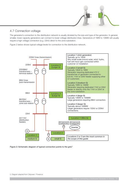
4.7 Connection voltageThe genera<strong>to</strong>r’s connection <strong>to</strong> the distribution network is usually dictated by the size and type of the genera<strong>to</strong>r. In general,smaller, lower capacity genera<strong>to</strong>rs can connect <strong>to</strong> lower voltage distribution lines. Genera<strong>to</strong>rs of 1MW <strong>to</strong> 10MW will usuallyrequire a high voltage connection (e.g. 22kV) direct <strong>to</strong> the zone substation.Figure 2 below shows typical voltage levels for connection <strong>to</strong> the distribution network.220kV220/66kVtransformers –terminal station66kV lines(sub-transmission66kV66/22kVtransformers –zone sub-station22kV220kV lines (transmission)Location 5(Larger G)Location 4(Large G)Location 1 (mini genera<strong>to</strong>r)Typically up <strong>to</strong> 10kWVery small-scale (micro) solar, wind, hydro,fuel cell micro-gen connected withincus<strong>to</strong>mer LV installationLocation 2 (small G)Typically 10kW <strong>to</strong> 1MWGenera<strong>to</strong>r requiring dedicated 415 Vtransformer or genera<strong>to</strong>r connected <strong>to</strong>6.6 kV, 11kV or 22kV feeder supplying otherLV cus<strong>to</strong>mersLocation 3 (medium G)Typically 1MW <strong>to</strong> 10MWGenera<strong>to</strong>r requiring dedicated 11kV or 22kVfeeder or directly on<strong>to</strong> the 11kV or 22kV atthe zone substation.Location 4 (large G)Typically 10MW <strong>to</strong> 100MWLarge genera<strong>to</strong>rs requiring 66kV connection.Location 5 (larger G)Typically above 100MWLarger genera<strong>to</strong>rs require 132kV or 220kVconnections.22/11kVdistributionfeedersCus<strong>to</strong>merLocation 1 (Mini G)Cus<strong>to</strong>merInverterGLocation 3medium GGLocation 2small GLocations 2 or 3 are the most common inthe scope of this guideFigure 2: Schematic diagram of typical connection points <strong>to</strong> the grid. 55. Diagram adapted from Citipower / Powercor.<strong>Guide</strong> <strong>to</strong> <strong>Connecting</strong> a <strong>Distributed</strong> Genera<strong>to</strong>r in Vic<strong>to</strong>ria - 15