Data Sheet for MJB4
Data Sheet for MJB4
Data Sheet for MJB4

You also want an ePaper? Increase the reach of your titles
YUMPU automatically turns print PDFs into web optimized ePapers that Google loves.
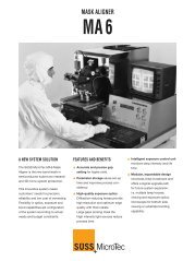
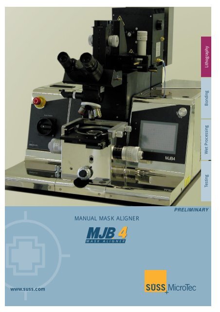
TestingWet ProcessingBondingLithographyMANUAL MASK ALIGNERPRELIMINARYwww.suss.com
PRINTING MODESUV400 UV300 UV250Soft Contact 2.0µm
SPECTRAL RANGESRange Wavelength Range Exposure lampsNear UV UV 400 (350 – 450nm) 200/350W HgMid UV UV 300 (280 – 350nm) 200/350W HgDeep UV UV 250 (240 – 260nm) 500W HgXeSUSS diffraction reducing exposure optics are incorporated in all <strong>MJB4</strong> configurations.EXPOSURE SYSTEMHigh Quality Exposure OpticsSUSS offers a variety of optical configurations designedto compensate diffraction effects <strong>for</strong> variousspectral ranges. Diffractions are a significant factorin the improvement of resolution and yield optimumresist sidewall slopes.Diffraction effects at the mask pattern edges limitthe achievable resolution. They are proportional tothe square root of the wavelength. There<strong>for</strong>e shorterwavelengths provide less diffraction. SUSS diffractionreducing exposure optics are available <strong>for</strong> thespectral ranges UV400, UV300 and UV250. All<strong>MJB4</strong> configurations incorporate the diffractionreducing SUSS optical system, individually optimized<strong>for</strong> the particular spectral region and the correspondingdesired resolution.Optical system of <strong>MJB4</strong> mask alignerSUSS is the only semiconductor equipment supplier offering diffraction reducing optical setupsConventionalSUSS OpticsExposure SystemStrong diffraction effectsfrom parallel illuminationSUSS diffractionreducing optics4PRELIMINARY
0.5µmLithographyReliable submicron printing with SUSS diffractionreducing optics.(1 micron PMMA, UV250, vacuum contact)Intensity distribution in the various spectralregions. The intensity scale of the graphics varies,there<strong>for</strong>e the intensities may not be directlycompared.EXPOSURE OPTICSUV300/400 Standard ConfigurationUV250 Submicron ConfigurationThe basic configuration of the <strong>MJB4</strong> achieves itsper<strong>for</strong>mance with the unfiltered spectrum of a200W high pressure mercury arc lamp and its associatedexposure system with diffraction reducedlight path. The <strong>MJB4</strong> standard is an excellent,extremely versatile tool <strong>for</strong> R&D and laboratoryapplications.The 200W lamp provides an intensity of more than40 mW/cm 2 at broadband and more than20mW/cm 2 at i-line.The <strong>MJB4</strong> exposure systems are manufacturedfrom Herasil and are suitable <strong>for</strong> processes usingnear UV (UV400) or mid UV (UV300). Filter elementsprovide the different spectral ranges of g, h and i-line of the mercury spectrum.The UV 250 exposure system incorporates Suprasillenses <strong>for</strong> deep UV with corresponding lightsources.For ozone removal the lamphouse can be optionallyequipped with an exhaust and cooling system.SUSS recommends the exhaust system whenworking with DUV.For process techniques in the UV250 spectral rangea suitable photoresist such as PMMA must beused. This resist is sensitive below 260nm only.The Suprasil lens system can also be combinedwith the 200W or 350 W Hg lamp and associatedfilter elements <strong>for</strong> processes in the UV400 or UV300regions.Expoure OpticsPRELIMINARY5
1234ALIGNMENT STAGE58 9Precise alignment of mask and wafer is crucial <strong>for</strong>all lithography processes. Alignment is per<strong>for</strong>medby moving the wafer, while keeping the mask stagestationary.XY alignment stageThe <strong>MJB4</strong> is equipped with a XY alignment stageusing high precision, backlash-free micrometerspindles <strong>for</strong> X, Y and .The travel range <strong>for</strong> X and Y is ±5mm, <strong>for</strong> ±5°.Substrate thickness compensation is easily adjustableallowing <strong>for</strong> a shift-free separation/contactmovement.WEC-System in the Alignment Stage.Soft contact <strong>for</strong> precise leveling. Inline verticalpneumatic clamping avoids any shifts.● 1 Mask Holder ● 2 Mask ● 3 Wafer ● 4 Chuck● 5 Chuck stage ● 6 Spindle● 7 Precise ball-bearing guide● 8 Pneumatic brake ● 9 Leveling pistons6The mechanically clamped mask holder is designed<strong>for</strong> quartz, glass or film masks. It is equipped withvacuum clamping <strong>for</strong> the mask. Mask holders andchucks are easily exchangeable. Existing MJB3equipment can be used on the <strong>MJB4</strong> with a specialmask holder frame.7The manual Z-movement allows a maximum substratethickness of up to 4mm.Fast and safe substrate loading/unloading is possiblewithout removing mask holder or mask.Direct Alignment by EyeMask targetsMisaligned mask and wafer targetsPerfectly aligned targetsAlignment■ Color image ■ Large field of view ■ Life-images, no risk of shift ■ Cost effective■ Limited to depth of focus of respective objective6PRELIMINARY
LithographyTopside alignment with M500 microscopeMANUAL OPTICALALIGNMENTThe human eye possesses a remarkable ability torecognize symmetry. The task to produce suitablealignment keys there<strong>for</strong>e consists of finding highcontrast figures where symmetry can be recognized.A simple example is placing a small crosswithin a large cross. The line width of the largecross is not significant, if both sides of the crosscan be observed.M604 Splitfield microscopeMICROSCOPESFor best alignment the gap between the edges ofthe small and the large crosses is critical. The minimumdistance is approximately 2µm. Typical valueslie between 3 and 5µm, depending on contrast andedge quality. If the gap between the small and largealignment target is 3µm, a misalignment of 0.5µmcauses a 40 percent intensity difference.SUSS has designed a range of alignment crossesmeeting all important requirements.Examples of 2µm MisalignmentThe high alignment accuracy is obtained throughthe use of high resolution microsopes.In addition alignment accuracy can be checkedbe<strong>for</strong>e exposure in all exposure modes especially invacuum contact.Standard topside alignment is per<strong>for</strong>med with theM604 Splitfield microscope. Equipped with 10xobjectives it offers a simultaneous viewing of maskand wafer. For small substrate alignment the SUSSsingle field microscope M500 might be a cost-effectivesolution. With both, the M604 and M500 analignment accuracy of 1µm or better is achievable.20µmCompetition:Optical misperception by simple crosshair alignment(recognition of misalignment hardly possible)SUSS:The combination of microscopes with a large depthsof focus DOF and wide range of advancedalignment marks enable highest alignment accuracy(immediate recognition of misalignment)For manual alignment the full objectives depth offocus is normally used. The line and space resolutionis approximately 1µm. It is not necessary torecognize submicron features in order to achievesubmicron alignment accuracy.Direct AlignmentPRELIMINARY7
M604Splitfield microscopeObjective 2,5x 5x 10x 20xResolution (µm) 4,2 2,2 1,1 0,9Depth of focus (µm) 195 51 13 4,5Field of view ø (mm) 4,65 2,33 1,16 0,58Magnification 47,3 94,6 189,2 378,3The <strong>MJB4</strong> can be equippedwith the M604 Splitfieldmicroscope and the M500Singlefield microscopeM500 Singlefield microscopeObjective 2,5x 5x 10x 20xResolution (µm) 4,2 2,2 1,1 0,9Depth of focus (µm) 518 132 33 10Field of view ø (mm) 8,80 4,40 2,20 1,10Magnification 25 50 100 200The high alignment accuracy is obtained throughthe use of special 20x high resolution microscopeobjectives. They are optically compensated <strong>for</strong>observation through the mask.Microscope OptionsFor demonstration and educational purposes bothmicroscopes can be optionally equipped with CCDcamera and monitor.Microscope ManipulatorFor fast microscope scanning of mask and wafer amicroscope manipulator is standard. It is equippedwith precise pneumatic brakes, vibration-, shift- andbacklash-free positioning. A travel range of±40mm in X, +30mm in Y, and -50mm allows <strong>for</strong>flat alignment of a four inch wafer/substrate.In case of working with a Singlefield microscope afast X scanning movement is available. A rotationadjustment <strong>for</strong> the SUSS Splitfield microscope in arange of ±4° is normal.Coarse and fine focus can be done with a convenientlycombined control. An automatic microscopelift protects the high magnification objectives withshort working distance, if the exposure cycle isinitiated or if the mask had to be loaded or unloaded.MicroscopeSUSS Singlefield microscope and TSAmanipulator8PRELIMINARY
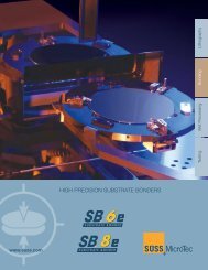
SUSS INFRAREDSYSTEMSFor backside or buried layers feature alignment theSUSS <strong>MJB4</strong> can be optionally equipped with aninfrared system. There are two principles of IR alignmentpossible: The SUSS IR transmitted illuminationsystem and the SUSS IR incident illuminationsystem. Both are applicable to materials transparentto wavelengths in the range from 400 to 1200nm.Both methods were incorporated <strong>for</strong> the handling ofIR transparent materials like GaAs, InP, Silicon etc.Infrared alignment can also be used to align toburied diffusion layers.LithographyFor IR alignment both microscopes, the M500Singlefield and the M604 Splitfield, can beemployed.Alignment Accuracy with IRDue to the specific design in most IR applicationsan alignment accuracy of ± 5µm (± 2µm under optimalprocess conditions) is achievable.<strong>MJB4</strong>CONFIGURATIONSThe SUSS <strong>MJB4</strong> submicron aligners are designed<strong>for</strong> the highest demands on resolution and alignmentaccuracy. They incorporate the highest SUSSquality in mechanics (alignment stage) and exposureoptics. For specific applications SUSS offers opticalset ups <strong>for</strong> UV250, UV300 and UV400.SUSS IR Alignment SystemFor Top Side / IR Aligment there are two microscopesavailable, the M500 Singlefield and the M604Splitfield microscope. As a special advantage the<strong>MJB4</strong> allows <strong>for</strong> an alignment check in all contactexposure modes.■ Infrared light source to be positionedmanually■ Special IR chucks available■ One (M500) or two (M604) video camerassensitive to wavelengths in therange from 400 to 1200nm■ Video monitor■ Dedicated IR light source■ Dedicated IR objectivesExposure Lamp Power SupplyThere are two options available. The standardpower supply <strong>for</strong> the 200W mercury lamp equippedwith a smooth lamp ignition system to prolong lamplife time. The lamps runs at constant power supplyonly and is adjustable between 150 and 250W.A more sophisticated power supply is the SUSSconstant intensity controller (CIC 1200). It enablesyou to run lamps at constant intensity as well as inconstant power. Each lamp can be adjusted to aspecific intensity or power level.For UV250 applications the CIC1200 is mandatory.ConfigurationsPRELIMINARY9
SUSS <strong>MJB4</strong> MASK ALIGNER STANDARDSMask and Wafer / SubstrateSubstrate Size Round: 1” up to 100 mm / 4”Square: 5x5 mm up to 100x100 / 4”x4”Wafer/substrate thicknessUp to 4mmMask Size2”x2” up to 5”x5”Mask thicknessUp to 4.8 mm / 190 milExposure SystemLamp House350WLamp Power200W; 350W; 500W (DUV with HG-XE lamp)Intensity 200W 45mW/cm2 at 405nm(over dia. 100mm area)30mW/cm 2 at 365 nm350W 90mW/cm 2 at 405nm45m/Wcm 2 at 365nm500W 20mW/cm 2 at 250nmUni<strong>for</strong>mity ≤3%SpectrumUV400 : 350 – 450nm (g, h, i-line)UV300 : 280 – 350nmUV250 : 240 – 260nmPrint ResolutionLines and Spaces; Resist AZ 5214E, 1µm, Wafer 100mmUV400 UV300 UV250Soft Contact 2.0µm
Top Side Microscope ManipulatorTravel Range X± 40mmTravel Range Y+ 30mm / -50mmTravel Range 0 ± 4°LithographyAlignment StageTravel Range X± 5mmTravel Range Y± 5mmTravel Range 0 ± 5°Mechanical resolution X,Y 0.1 µmMechanical resolution 0 4x10 -5 °UtilitiesVacuum Pressure < -0.8 bar ( 5.5 bar (81 psi)Consumption 0.5 m 3 /hNitrogen Pressure >1.5 bar (22 psi)Consumption 200W lamp: 0.2 m 3 /h, 350W lamp: 0.35 m 3 /h500W lamp: 0.7 m 3 /hElectrical Power Input 95V – 260V, 50/60HzConsumption200W lamp: 500 VA, 350W lamp: 1650 VA500W lamp: 2250 VAPhysical Width x Depth x Height 600 x 800 x 650mm (24 x 31 x 28”)WeightUp to 150 kg (331 pds)<strong>Data</strong> depends on individual process conditions and can vary according to equipment configurations. Not all specifications may be valid simultaneously.Illustrations in this brochure are not legally binding. Design and specification of custom built machines depends on individual conditions and can varyaccording to equipment configurations.Small footprint:Width 600mm 24”Depth 800mm 31”Height 650mm 28”= 0.5 m 2 (5ft 2 )SUSS <strong>MJB4</strong>PRELIMINARY11
EUROPESUSS MicroTec Lithography GmbHSchleissheimer Str. 90 · D-85748 Garching b. München · GermanyPhone (+49)-(0) 89/3 20 07-0 · Fax (+49)-(0) 89/3 20 07-162SUSS MicroTec Test Systems GmbHSüss-Strasse 1 · D-01561 Sacka b. Dresden · GermanyPhone (+49)-(0) 35240-73-0 · Fax (+49)-(0) 35240-73-700SUSS MicroTec S.A.Avenue des Colombières · F-74490 Saint Jeoire · FrancePhone (+33)-(0) 4 50 35 83 92 · Fax (+33)-(0) 4 50 35 88 01SUSS MicroTec Ltd.Hogwood Ind. Estate, 23, Ivanhoe RoadFinchampstead, Wokingham, Berkshire RG40 4QQ, EnglandPhone (+44)-(0) 1189-732144 · Fax (+44)-(0) 1189-734395NORTH AMERICASUSS MicroTec Inc.228 Suss Drive · Waterbury Center, VT 05677 · USAPhone (+1)-802-244-5181 · Fax (+1)-802-244-5103SUSS MicroTec Inc.Western Regional Sales Office, 8240 So. Kyrene Road Suite 101Tempe, AZ 85284-2117Phone (+1)-480-557-9370 · Fax (+1)-480-557-9371ASIASUSS MicroTec Company Ltd.3388/92-93 · 25th Floor · Sirinrat Bldg.Rama IV Road · Klongtoey · Bangkok 10110 · ThailandPhone (+66)-(0) - 2350 6038 · Fax (+66)-(0) -2633 5728SUSS MicroTec AGTaiwan Representative Office8F-11, 13 · No. 81 · Shui-Lee Road · Hsin-Chu · 300 · TaiwanPhone (+886)-(3) 5169098 · Fax (+886)-(3) 5169262SUSS MicroTec AGShanghai Office580 Nanjing W. Rd · Nanzheng Building Room 606 · 200041 ShanghaiPhone (+86) 21-52340432 · Fax (+86) 21-52340430JAPANSUSS MicroTec KKGITC 1-18-2, Hakusan, Midori-ku, Yokohama, Kanagawa, Japan 226-0006Phone (+81)-45-931-5600 · Fax (+81)-45-931-5601Subject to change without prior notice<strong>MJB4</strong> , WeAl, 04/2003, #1www.suss.comPRELIMINARY