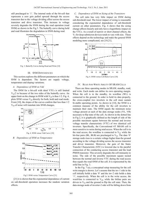
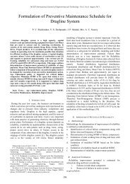
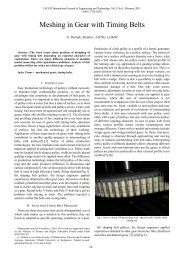
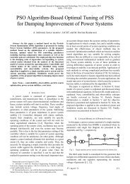
IACSIT International Journal <strong>of</strong> Engineering and Technology, Vol.3, No.3, June 2011still precharged to ‘1’. The internal node <strong>of</strong> the bit-cell thatrepresents a zero gets pulled upward through the accesstransistor due to the voltage dividing effect across the accesstransistor and drive transistor. This increase in voltageseverely degrades the SNM during the read operation (readSNM) as shown in the Fig.3. The butterfly curve during holdand read illustrates the degradation in SNM during read.C. Dependence <strong>of</strong> SNM on Sizing <strong>of</strong> the TransistorsThe cell ratio has very little impact on SNM duringsub-threshold read. The lower impact <strong>of</strong> sizing is reasonableconsidering the exponential dependence <strong>of</strong> sub-thresholdcurrent on other parameters. Fig. 6 shows that the sizingchange affects linearly and only have a logarithmic impact onthe VTCs. As a result <strong>of</strong> narrow or short channel effects, theV T for deep submicron devices tends to vary with size. Theseeffects depend on the technology and make the general SNMmodeling more complicated, see [10,21].Fig. 3. Butterfly Curves during Read and Write [10]III. SNM DEPENDENCIESThis section explores the different parameters on which theSNM is dependent. The factors are supply voltage,temperature and doping variations.A. Dependence <strong>of</strong> SNM on VddThe SNM for a bit-cell with ideal VTCs is still limitedV dd /2 to because <strong>of</strong> the two sides <strong>of</strong> the butterfly curve. Anupper limit on the change in SNM with V dd is thus 1/2. Fig. 4,plots SNM versus V dd directly for both, hold and read mode.From [10], the slopes <strong>of</strong> the curves confirm that less than 1/2V dd <strong>of</strong> noise will translate into SNM changes.Fig. 4. SNM versus Vdd Curve [10]B. Dependence <strong>of</strong> SNM on TemperatureFig.5. SNM versus Temperature Curve [21][21] it is shown that the exponential dependence <strong>of</strong> currenton sub-threshold operation increases the random variationeffects.Fig. 6. SNM versus Cell Ratio Curve [10]IV. READ AND WRITE ABILITY OF <strong>SRAM</strong> CELLSThere are three operating modes in <strong>SRAM</strong>, standby, read,and write. Each mode can define its own operating margin.When the cell is in the standby, its wordline (WL) isconnected to the ground. In order to hold its data properly,the cross-coupled two inverters in the cell must sustainbi-stable operating points. As shown in [14], the SNM is acommon measure <strong>of</strong> the ability for the cell inverters tomaintain their state. The SNM equals the minimum noisevoltage present at each <strong>of</strong> the data storage nodes (VL, VR)necessary to flip state <strong>of</strong> the cell. As shown in the dotted linein Fig.2, it is graphically defined as the length <strong>of</strong> side <strong>of</strong> thepossible maximum square between the normal and inversevoltage transfer characteristic (VTC) <strong>of</strong> two identical cellinverters. Specifically, the Conventional 6T <strong>SRAM</strong> cell ismore sensitive to noise during read access. When the cell is in,the read access, the wordline is connected to V dd while thebit-line pairs (BL, BLB) are precharged to V dd . The data ‘0’storage node rises to a certain voltage higher than the groundaccording to the voltage dividing across the access transistorand driver transistor. Moreover, the gain <strong>of</strong> the <strong>Static</strong>Transfer Characteristic (STC) is lowered due to the parallelconnection <strong>of</strong> the conducting access transistor and the loadPMOS transistor. This severely degrades the cell immunity tonoise. The side <strong>of</strong> the possible maximum square nestedbetween the normal and inverse VTC during the read accessthus equals the read SNM <strong>of</strong> the cell. It is represented by thesolid line in Fig. 3.In the Fig. 7 (a), a conceptual setup measuring for the cellwrite margin is shown. Let’s assume that the inv-1 side in thecell initially holds a data ‘0’ and the inv-2 side holds a data‘1’, respectively. When the cell is in the write access, theword-line is connected to V dd , while the bitline pairs aredriven to V dd and the ground to flip the cell state. Then, thedata storage node <strong>of</strong> inverter-2 side will be falling down from305
IACSIT International Journal <strong>of</strong> Engineering and Technology, Vol.3, No.3, June 2011V . dd The figure plots the respective transfer characteristics <strong>of</strong>the cell inverters in this write access. Particularly, whenobtaining the characteristic <strong>of</strong> inverter-2 side, the wordlinevoltage <strong>of</strong> its access transistor is used as an input signal,,while the input node <strong>of</strong> inverter-2 is set to V OL the lowestvoltage level <strong>of</strong> the output <strong>of</strong> inverter-1. Since the output <strong>of</strong>inverter-1, V DN , will not be reversed until the output <strong>of</strong>inverter-2, V /DN , reaches a logic threshold voltage (V LT ) <strong>of</strong>inverter-1, the margin 0V is assumed to occur when V /DNequals V LT <strong>of</strong> inverter-1. Here, the voltage level <strong>of</strong> WL forthe case <strong>of</strong> margin 0V is referred to as VWL0. This is atrigger for the cell to begin a toggle.,Because the voltage level <strong>of</strong> accessed WL is V dd thewrite margin (WM) is thus defined as V dd –VWL0. This writemargin quantifies a surplus amount between the accessed WLvoltage and the minimum WL voltage required for the cell t<strong>of</strong>lip its contents.increases, the write margin improves. The write margin inthis case is 0.6V. This voltage is above V , T so, the PMOS hasweakened relative to the NMOS because the mobility.dominates the differences in V T Even at 0.6V, the writemargin is barely negative for the worst-case corner and thisdoes not account for local V T variations. For these reasons,V dd at 0.6V is the best case voltage for which we can expecttraditional write operations to work for a sub-thresholdmemory in this 65-nm process [8].A. 7T <strong>SRAM</strong> CellA read SNM free <strong>SRAM</strong> is implemented in [8]. But thelimitation was the write operations at the lower V dd cannot beperformed and the read operations at low V dd levels result inlow storage destructions in <strong>SRAM</strong> cells due to the leakagecurrent <strong>of</strong> PMOS cells. The other 7T <strong>SRAM</strong> cell (Fig. 8) usesa novel write mechanism which depends only on one <strong>of</strong> the2-bit lines to perform a write operation, which reduces theactivity factor <strong>of</strong> discharging the bit-line pair. Simulationshows that the write power saving is at least 49% [8,9]. Both,the read delay and the static noise margins are maintainedafter carefully sizing the cell transistors. The limitation isarea overhead from conventional 6T <strong>SRAM</strong> cell [9].Fig. 8 7T <strong>SRAM</strong> Cell with Novel Write Mechanism [9]B. 8T <strong>SRAM</strong> CellA dual-port 8T-<strong>SRAM</strong> cell is created by adding two dataoutput transistors to a conventional 6T-<strong>SRAM</strong> cell (Fig. 9).Separation <strong>of</strong> data retention element and data output elementmeans there will be no correlation between read SNM andI cell .(a)(b)Fig. 7. Operating <strong>Margin</strong> <strong>of</strong> 6T <strong>SRAM</strong> Cell(a) SNM during Standby and Read and (b) Write <strong>Margin</strong> [14]V. <strong>SRAM</strong> TOPOLOGIES<strong>Various</strong> <strong>SRAM</strong> topologies have been analyzed in thissection and implemented at various process technologies.<strong>Various</strong> types <strong>of</strong> <strong>SRAM</strong>s are implemented and the stabilityfactor (SNM) has been analyzed for them.The conventional 6T <strong>SRAM</strong> Cell is implemented at 65nmnode and the analysis <strong>of</strong> the stability is done. A 6T <strong>SRAM</strong> isdesigned in the 65-nm process. In this the iso-size PMOSdevices are stronger in sub-V T than NMOS by roughly anorder <strong>of</strong> magnitude, which makes the write functionalitymore challenging. The general trend showing animprovement <strong>of</strong> write operation, i.e., more negative margin,at higher temperature occurs because the PMOS transistorsweaken relative to NMOS as temperature rises. As V ddFig. 9 Dual-Port 8T <strong>SRAM</strong> Cell [14]In contrast to the worst normalized read SNM value <strong>of</strong>0.20 for a conventional 6T-<strong>SRAM</strong> cell, here the value is 1.22,and there is no I cell degradation. It is also possible here, tolower the Vth <strong>of</strong> the NMOS transistors in a <strong>SRAM</strong> cell inorder to improve I cell . As shown in [9], this 8T-<strong>SRAM</strong> cellhas 30% more area than a conventional 6T-<strong>SRAM</strong> cell,however. The 30% area overhead is composed <strong>of</strong> not only thetwo added transistors but also <strong>of</strong> the contact area <strong>of</strong> the WWL,the word-line for write operations. While WL contact area isconventionally assigned to the boundary line between two<strong>SRAM</strong> cells, in this <strong>SRAM</strong> cell the WWL contact area isassigned to within a cell, as shown in Fig. 9.An UDVS (Ultra Dynamic Voltage Scaling) 8T-<strong>SRAM</strong>(Fig. 10) is proposed in this read and write ports aredecoupled, (BVSS) virtual ground node for read buffer and iskept at V dd is cell is not accessed. Mchd is the virtual supplynode and its voltage can be brought down during write accessupto weaken PMOS. A 64Kb <strong>SRAM</strong> fabricated with a die306