Thermowell with flange (solid-machined) Model ... - WIKA Polska
Thermowell with flange (solid-machined) Model ... - WIKA Polska
Thermowell with flange (solid-machined) Model ... - WIKA Polska

Create successful ePaper yourself
Turn your PDF publications into a flip-book with our unique Google optimized e-Paper software.
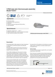
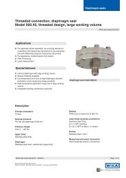
<strong>Thermowell</strong>s<strong>Thermowell</strong> <strong>with</strong> <strong>flange</strong> (<strong>solid</strong>-<strong>machined</strong>)<strong>Model</strong> TW10-F, full penetration weld design<strong>Model</strong>s TW10-P and TW10-R, <strong>with</strong> double fillet weld<strong>WIKA</strong> data sheet TW 95.10Applications■■Petrochemical industry, on-/offshore, plant construction■■For high process loadsSpecial features■■Heavy-duty design■■<strong>Model</strong> TW10-F: Full penetration weld version<strong>Model</strong> TW10-P: With double fillet weldweld seam strength a = 3 mm<strong>Model</strong> TW10-R: With double fillet weldweld seam strength a = 6 mm■■For highly corrosion-resistant coatings■■Possible thermowell forms:- tapered, straight or stepped- "Quill Tip" version (<strong>with</strong> open tip)■■Welding process test to ASME Sec. IX<strong>Thermowell</strong> <strong>with</strong> <strong>flange</strong>, model TW10DescriptionEach thermowell is an important component of anytemperature measurement point. It is used to separate theprocess from the surrounding area, thus protecting theenvironment and operating personnel and keeps aggressivemedia, high pressures and flow rates from the temperaturesensor itself and thereby enables the thermometer to beexchanged during operation.Based on the almost limitless application possibilities, thereare a large number of variants, such as thermowell designsor materials. The type of process connection and the basicmethod of manufacture are important design differentiationcriteria. A basic differentiation can be made betweenthreaded and weld-in thermowells, and those <strong>with</strong> <strong>flange</strong>connections.Furthermore, one can differentiate between fabricated and<strong>solid</strong>-<strong>machined</strong> thermowells. Fabricated thermowells areconstructed from a tube, that is closed at the tip by a welded<strong>solid</strong> tip. Solid-<strong>machined</strong> thermowells are manufactured frombarstock.The TW10 series of <strong>solid</strong>-<strong>machined</strong> thermowells <strong>with</strong> <strong>flange</strong>connection are suitable for use <strong>with</strong> numerous electrical andmechanical thermometers from <strong>WIKA</strong>.Due to the heavy-duty design, these international designthermowells are the first choice for use the chemical andpetrochemical industries and in plant construction.<strong>WIKA</strong> data sheet TW 95.10 ∙ 06/2012Page 1 of 4
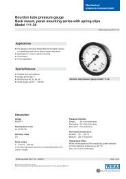
Standard version<strong>Thermowell</strong> materialStainless steel 304/304L, 316/316L, A105, 1.4571, 1.4404,special materialsFlangeBlind <strong>flange</strong> per ASME, EN 1092-1, DIN 2527Connection to thermometer½ NPT, G ½ (female)"Quill Tip" version <strong>with</strong> weld-in connection ½" and ¾"Bore sizeØ 6.6 mm, Ø 8.5 mmInsertion length UTo customer specificationConnection length H57 and 83 mm (standard)Others on requestCoating■■PFACoat thickness min. 0.4 mm (standard) ormin. 0.6 mm (special design)■■ECTFE (Halar ® )Coat thickness min. 0.6 mmMax. process temperature, process pressureDepending on■■<strong>Thermowell</strong> design- Dimensions- Material- Coating- Flange pressure rating■■Process conditions- Flow rate- Density of mediumOptions■■Other <strong>flange</strong>s, dimensions and materials■ ■ "Quill Tip" version■■Tantalum coating for wetted parts (insertion length U +max. 3 mm)■■Quality certificates■■<strong>Thermowell</strong> calculation to ASME PTC 19.3-2010is recommended in critical applications as a <strong>WIKA</strong>engineering serviceFor further information see Technical information IN 00.15"Strength calculation for thermowells".Halar ® ECTFE is a registered trademark of the company Solvay Solexis.Dimensions in mm<strong>Model</strong> TW10-F<strong>Model</strong>s TW10-P, TW10-R3111923.023336276.02Legend:H Connection lengthU Insertion lengthN Connection to thermometerØ B Bore sizeØ Q Root diameterØ V Tip diameterØ Bd Head diameter:T t Tip thickness (6.5 mm)Page 2 of 4 <strong>WIKA</strong> data sheet TW 95.10 ∙ 06/2012
"Quill Tip" versionStandardOption: straight11536128.01ASME <strong>flange</strong>s, tapered thermowell formDN PN Dimensions in mm Weight in kgin lbs H Ø Q Ø V Ø B Ø Bd U = 4" U = 13" U = 22"1" 150 2 ¼" (approx. 57 mm) 22 16 6.6 or 8.5 30 1.4 1.9 2.3300 2 ¼" (approx. 57 mm) 22 16 6.6 or 8.5 30 2.1 2.6 3.0600 2 ¼" (approx. 57 mm) 22 16 6.6 or 8.5 30 2.3 2.8 3.21500 3 ¼" (approx. 83 mm) 22 16 6.6 or 8.5 30 4.3 4.8 5.21 ½" 150 2 ¼" (approx. 57 mm) 25 19 6.6 or 8.5 30 1.8 2.4 3.0300 2 ¼" (approx. 57 mm) 25 19 6.6 or 8.5 30 3.3 3.9 4.5600 2 ¼" (approx. 57 mm) 25 19 6.6 or 8.5 30 4.0 4.7 5.31500 3 ¼" (approx. 83 mm) 25 19 6.6 or 8.5 30 6.4 7.1 7.72" 150 2 ¼" (approx. 57 mm) 25 19 6.6 or 8.5 30 2.5 3.1 3.7300 2 ¼" (approx. 57 mm) 25 19 6.6 or 8.5 30 3.7 4.3 4.9600 2 ¼" (approx. 57 mm) 25 19 6.6 or 8.5 30 4.2 4.9 5.51500 3 ¼" (approx. 83 mm) 25 19 6.6 or 8.5 30 11.0 11.6 12.3EN and DIN <strong>flange</strong>s, tapered thermowell form(only for welding version <strong>with</strong> fillet weld, a = 3 or 6 mm on both sides)DN PN Dimensions in mm Weight in kgin bar H Ø Q Ø V Ø B Ø Bd U = 160 mm U = 500 mm25 40 45 22 16 6.2 ... 10.2 30 1.9 2.663/64 45 22 16 6.2 ... 10.2 30 3.2 3.9100 45 22 16 6.2 ... 10.2 30 3.2 3.940 40 45 25 19 6.2 ... 10.2 30 3.1 4.063/64 45 25 19 6.2 ... 10.2 30 4.8 5.7100 45 25 19 6.2 ... 10.2 30 4.8 5.750 40 45 25 19 6.2 ... 10.2 30 3.9 4.863/64 45 25 19 6.2 ... 10.2 30 5.2 6.1100 45 25 19 6.2 ... 10.2 30 6.6 7.580 40 60 25 19 6.2 ... 10.2 30 6.6 7.563/64 60 25 19 6.2 ... 10.2 30 7.6 8.5100 60 25 19 6.2 ... 10.2 30 10.2 11.1100 40 60 25 19 6.2 ... 10.2 30 8.3 9.263/64 60 25 19 6.2 ... 10.2 30 10.9 11.8100 60 25 19 6.2 ... 10.2 30 15.0 15.9<strong>WIKA</strong> data sheet TW 95.10 ∙ 06/2012Page 3 of 4
Suitable stem lengths (dial thermometers)Connection typeStem length l1S, 4, 5 l 1 = U + H - 10 mm2 l 1 = U + H - 30 mmSealing face roughnessFlange standardAARHin µinchRain µmRzin µmASME B16.5 Stock finish 125 ... 250 3.2 ... 6.3 -Smooth finish < 125 < 3.2 -RTJ < 63 < 1.6 -Tongue/groove < 125 < 3.2 -EN 1092-1 Form B1 - 3.2 ... 12.5 12.5 ... 50Form B2 - 0.8 ... 3.2 3.2 ... 12.5DIN 2527 Form C - - 40 ... 160Form E - - < 16Ordering information<strong>Model</strong> / <strong>Thermowell</strong> form / <strong>Thermowell</strong> material / Flange material / Head diameter / Connection to the thermometer / Bore Ø B /Nominal diameter DN / Pressure rating PN / Sealing face / Wall thickness of <strong>flange</strong> nozzle / insertion length U / Connectionlength H / Coating / Assembly <strong>with</strong> thermometer / Certificates / Options© 2008 <strong>WIKA</strong> Alexander Wiegand SE & Co. KG, all rights reserved.The specifications given in this document represent the state of engineering at the time of publishing.We reserve the right to make modifications to the specifications and materials.Page 4 of 4 <strong>WIKA</strong> data sheet TW 95.10 ∙ 06/201206/2012 GB<strong>WIKA</strong> Alexander Wiegand SE & Co. KGAlexander-Wiegand-Straße 3063911 Klingenberg/GermanyTel. (+49) 9372/132-0Fax (+49) 9372/132-406E-mail info@wika.dewww.wika.de