DigiLED DMX CA - Vossloh Schwabe
DigiLED DMX CA - Vossloh Schwabe
DigiLED DMX CA - Vossloh Schwabe

You also want an ePaper? Increase the reach of your titles
YUMPU automatically turns print PDFs into web optimized ePapers that Google loves.
Operation Manual <strong>DigiLED</strong> <strong>DMX</strong> <strong>CA</strong> GB 1/5 March, 2009<br />
<strong>DigiLED</strong> <strong>DMX</strong> <strong>CA</strong><br />
WU-ST-003-<strong>DigiLED</strong>-<strong>DMX</strong> <strong>CA</strong> (Ref. No.: 186153)<br />
1 Introduction<br />
1.1 Product Description<br />
<strong>DigiLED</strong> <strong>DMX</strong> <strong>CA</strong> units are designed to enable individual colour<br />
control of LED modules in 24 V <strong>CA</strong> assembly systems. The<br />
digital interface was designed in compliance with the <strong>DMX</strong>512<br />
standard (DIN 56930-2) and is therefore suitable for connection<br />
to <strong>DMX</strong>512 control units.<br />
The <strong>DMX</strong> transfer protocol (digital multiplex for 512 channels) is<br />
used for controlling <strong>DigiLED</strong> <strong>DMX</strong> <strong>CA</strong> units. This standard was<br />
defined by the United States Institute for Theatre Technology<br />
(USITT). As a system control device, <strong>DigiLED</strong> <strong>DMX</strong> <strong>CA</strong> serves to<br />
control the brightness of high- and/or low-power LED modules<br />
that are of common anode design. Please refer to the<br />
publication entitled "USITT: <strong>DMX</strong>512/1990 Digital Data<br />
Transmission Standard for Dimmers and Controllers" for the full<br />
wording of the <strong>DMX</strong>512 standard.<br />
2<br />
Description of Functions<br />
2.1 Functional Characteristics<br />
The software integrated in a <strong>DigiLED</strong> <strong>DMX</strong> <strong>CA</strong> unit uses <strong>DMX</strong><br />
signals to generate the four PWM control signals (RGBW)<br />
needed for colour control of LED modules in a 24 V <strong>CA</strong> system.<br />
The four PWM control signals are assigned in accordance with<br />
the <strong>DMX</strong> address to which the <strong>DigiLED</strong> <strong>DMX</strong> <strong>CA</strong> unit was set<br />
(see 2.2.1).<br />
The set <strong>DMX</strong> address is recognised and stored as soon as the<br />
unit is connected to the supply voltage. Any changes made to<br />
the <strong>DMX</strong> address will only be recognised and stored if the<br />
<strong>DigiLED</strong> <strong>DMX</strong> <strong>CA</strong> unit is disconnected from the supply voltage<br />
for a minimum of 5 seconds before being reconnected.<br />
Technical Specifications:<br />
• 1 x <strong>DMX</strong> input to connect <strong>DMX</strong>-compatible control units;<br />
polarity must be observed<br />
1 x active <strong>DMX</strong> output for transferring and amplifying the<br />
<strong>DMX</strong> signal; polarity must be observed<br />
4 x PWM outputs (RGBW)<br />
Control signal range: 0 % ...100 %<br />
All channels are protected against short-circuiting and overload:<br />
in the event of short-circuiting, the channel will make<br />
five attempts to restart. Should these remain unsuccessful,<br />
the respective channel will shut down. Once the problem<br />
has been eliminated, the channel must be restarted (24 V<br />
supply)<br />
Overheating protection: should the tc temperature be<br />
exceeded, the output circuit will automatically shut down.<br />
Once the problem has been eliminated (i.e. the device<br />
has cooled down again sufficiently), the unit will restart<br />
automatically<br />
A BUS termination resistor can be activated (see 2.2.2)<br />
2.2 Settings<br />
A New Lighting Experience<br />
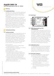
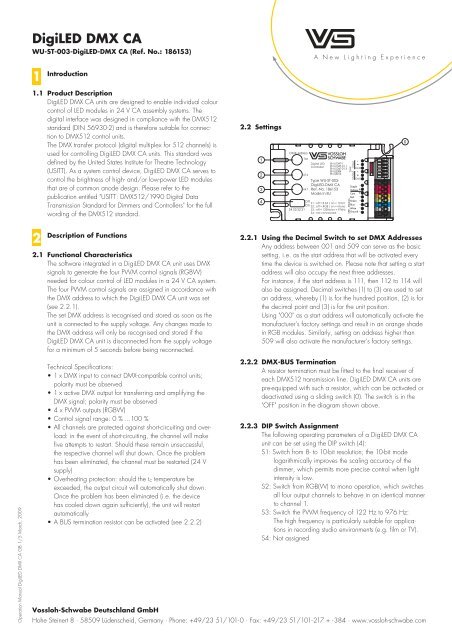
2.2.1 Using the Decimal Switch to set <strong>DMX</strong> Addresses<br />
Any address between 001 and 509 can serve as the basic<br />
setting, i.e. as the start address that will be activated every<br />
time the device is switched on. Please note that setting a start<br />
address will also occupy the next three addresses.<br />
For instance, if the start address is 111, then 112 to 114 will<br />
also be assigned. Decimal switches (1) to (3) are used to set<br />
an address, whereby (1) is for the hundred position, (2) is for<br />
the decimal point and (3) is for the unit position.<br />
Using "000" as a start address will automatically activate the<br />
manufacturer's factory settings and result in an orange shade<br />
in RGB modules. Similarly, setting an address higher than<br />
509 will also activate the manufacturer's factory settings.<br />
2.2.2 <strong>DMX</strong>-BUS Termination<br />
A resistor termination must be fitted to the final receiver of<br />
each <strong>DMX</strong>512 transmission line. <strong>DigiLED</strong> <strong>DMX</strong> <strong>CA</strong> units are<br />
pre-equipped with such a resistor, which can be activated or<br />
deactivated using a sliding switch (0). The switch is in the<br />
"OFF" position in the diagram shown above.<br />
2.2.3 DIP Switch Assignment<br />
The following operating parameters of a <strong>DigiLED</strong> <strong>DMX</strong> <strong>CA</strong><br />
unit can be set using the DIP switch (4):<br />
S1: Switch from 8- to 10-bit resolution; the 10-bit mode<br />
logarithmically improves the scaling accuracy of the<br />
dimmer, which permits more precise control when light<br />
intensity is low.<br />
S2: Switch from RGB(W) to mono operation, which switches<br />
all four output channels to behave in an identical manner<br />
to channel 1.<br />
S3: Switch the PWM frequency of 122 Hz to 976 Hz:<br />
The high frequency is particularly suitable for applications<br />
in recording studio environments (e.g. film or TV).<br />
S4: Not assigned<br />
<strong>Vossloh</strong>-<strong>Schwabe</strong> Deutschland GmbH<br />
Hohe Steinert 8 · 58509 Lüdenscheid, Germany · Phone: +49/23 51/101-0 · Fax: +49/23 51/101-217 + -384 · www.vossloh-schwabe.com<br />
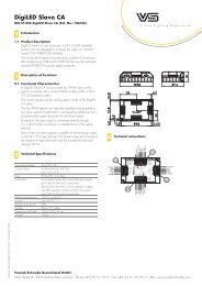
1<br />
2<br />
3<br />
4<br />
<strong>DMX</strong>-Adress<br />
1xx<br />
+<br />
Digital LED<br />
Controller<br />
x1x<br />
EN 61347-1<br />
EN 61347-2-11<br />
EN 61347-2-13<br />
EN 62384<br />
EN 55015<br />
GND<br />
+<br />
Type WU-ST-003-<br />
GND<br />
<strong>DigiLED</strong>-<strong>DMX</strong> <strong>CA</strong><br />
xx1 Ref.-No. 186153<br />
Made in EU<br />
Off<br />
S1:off=8bit/on=10bit<br />
On S2 : off = RGB / on = Mono<br />
S4 S3 S2 S1 S3 : off = 122Hz/on = 976Hz<br />
S4 : not connected<br />
Supply -<br />
Voltage +<br />
Com. +<br />
Red -<br />
Green -<br />
Blue -<br />
White -<br />
Ground -<br />
<strong>DMX</strong><br />
Output Input<br />
LED - Modules<br />
0
Operation Manual <strong>DigiLED</strong> <strong>DMX</strong> <strong>CA</strong> GB 2/5 March, 2009<br />
<strong>DigiLED</strong> <strong>DMX</strong> <strong>CA</strong><br />
WU-ST-003-<strong>DigiLED</strong>-<strong>DMX</strong> <strong>CA</strong> (Ref. No.: 186153)<br />
3<br />
Technical Data<br />
Operating Voltage 23 to 25 V DC<br />
Current consumption max. 5 A (see table 4.2)<br />
Fuse protection T5 A 250 V, safety fuse<br />
Connection 8-pole push-in terminal for supply voltage<br />
and LED assembly modules in 24 V <strong>CA</strong> system<br />
(see table 4.2)<br />
6-pole push-in terminal for the <strong>DMX</strong>512 interface<br />
Ambient temperature –20 °C to +45 °C<br />
tc point max. 60 °C<br />
Degree of protection IP20<br />
Casing Plastic, PC white<br />
Dimensions (LxWxH) 95 x 60 x 30 mm<br />
Weight 75 g<br />
4<br />
1<br />
2<br />
3<br />
4<br />
Terminal Connections<br />
<strong>DMX</strong>-Adress<br />
1xx<br />
+<br />
Digital LED<br />
Controller<br />
x1x<br />
EN 61347-1<br />
EN 61347-2-11<br />
EN 61347-2-13<br />
EN 62384<br />
EN 55015<br />
GND<br />
+<br />
Type WU-ST-003-<br />
GND<br />
<strong>DigiLED</strong>-<strong>DMX</strong> <strong>CA</strong><br />
xx1 Ref.-No. 186153<br />
Made in EU<br />
Off<br />
S1:off=8bit/on=10bit<br />
On S2 : off = RGB / on = Mono<br />
S4 S3 S2 S1 S3 : off = 122Hz/on = 976Hz<br />
S4 : not connected<br />
Supply -<br />
Voltage +<br />
Com. +<br />
Red -<br />
Green -<br />
Blue -<br />
White -<br />
Ground -<br />
4.1 <strong>DMX</strong> Terminal<br />
Terminal Function Recommended Lead Product<br />
Input <strong>DMX</strong> + + Connection for <strong>DMX</strong> signal (input) BUS line with an impedance value <strong>DMX</strong> unit<br />
Input <strong>DMX</strong> – – Connection for <strong>DMX</strong> signal (input) of 120 Ohm<br />
Input GND Ground (possibly for shielding the <strong>DMX</strong> line)<br />
Output <strong>DMX</strong> + + Connection for <strong>DMX</strong> signal (output)<br />
Output <strong>DMX</strong> – – Connection for <strong>DMX</strong> signal (output)<br />
Output GND Ground (possibly for shielding the <strong>DMX</strong> line)<br />
4.2 Terminal Block 24 V and Module Connection<br />
<strong>DMX</strong><br />
Output Input<br />
LED - Modules<br />
0<br />
Input <strong>DMX</strong><br />
Output <strong>DMX</strong><br />
24VDC<br />
+ module<br />
red<br />
green<br />
blue<br />
white<br />
– module<br />
83.5<br />
29 93<br />
Pole Colour Coding Max. Current<br />
Carrying Capacity<br />
Function Recommended Lead Connection<br />
1 Black 5 A Supply line for optional 24 V converter (GND) Standard two-strand supply lead 24 V DC converter<br />
2 Red 5 A Supply line for optional 24 V converter (+24 V) (0.5–1.5 mm2 )<br />
3 Red 5 A Supply line for LED assembly modules (+24 V) High Power feed in cable LED assembly modules<br />
4 Orange 1.25 A PWM signal line for channel 1/Red (Ref. No. 535900) or module group for<br />
5 Green 1.25 A PWM signal line for channel 2/Green or 24 V <strong>CA</strong> system<br />
6 Blue 1.25 A PWM signal line for channel 3/Blue Standard six-strand lead or<br />
7 Grey 1.25 A PWM signal line for channel 4/White (e.g.: LIYY 6X0.75 mm²) PCB distributor or slave<br />
8 Black 5 A Supply line for LED assembly modules (GND) board for 24 V <strong>CA</strong> system<br />
<strong>Vossloh</strong>-<strong>Schwabe</strong> Deutschland GmbH<br />
Hohe Steinert 8 · 58509 Lüdenscheid, Germany · Phone: +49/23 51/101-0 · Fax: +49/23 51/101-217 + -384 · www.vossloh-schwabe.com<br />
58<br />
48.5<br />
50<br />
74<br />
tc=60°C<br />
4.5<br />
4.5<br />
10
Operation Manual <strong>DigiLED</strong> <strong>DMX</strong> <strong>CA</strong> GB 3/5 March, 2009<br />
<strong>DigiLED</strong> <strong>DMX</strong> <strong>CA</strong><br />
WU-ST-003-<strong>DigiLED</strong>-<strong>DMX</strong> <strong>CA</strong> (Ref. No.: 186153)<br />
5<br />
<strong>DigiLED</strong> <strong>DMX</strong> <strong>CA</strong> Connections<br />
5.1 Input and <strong>DMX</strong> Terminal<br />
<strong>DMX</strong>: Connect <strong>DigiLED</strong> <strong>DMX</strong> <strong>CA</strong> to the <strong>DMX</strong> control unit<br />
using the <strong>DMX</strong> terminal. Further <strong>DMX</strong> units can be cascaded<br />
(up to a maximum of 32 devices) by creating an active<br />
output (<strong>DMX</strong> output). In so doing, the <strong>DMX</strong> signal can be<br />
connected through from <strong>DigiLED</strong> to <strong>DigiLED</strong> unit.<br />
Voltage supply: <strong>DigiLED</strong> <strong>DMX</strong> <strong>CA</strong> is supplied with 24 V DC<br />
via terminals 1 and 2 (see table 4.2).<br />
<strong>DigiLED</strong> Colour control<br />
<strong>DigiLED</strong> Manual <strong>CA</strong><br />
(Ref. No.: 186136)<br />
<strong>DigiLED</strong> DALI <strong>CA</strong><br />
(Ref. No.: 186138) -<br />
24V<br />
+<br />
<strong>DigiLED</strong> Push <strong>CA</strong> +<br />
(Ref. No.: 186144) R<br />
G<br />
<strong>DigiLED</strong> <strong>DMX</strong> <strong>CA</strong> B<br />
(Ref. No.: 186153) W<br />
-<br />
(Layout of connection terminals depend<br />
on colour control unit)<br />
Converter LEDLine EDX<br />
230 V ~<br />
LEDLine EDXe 110 ( Ref. No.: 186055)<br />
LEDLine EDXe 120 ( Ref. No.: 186129)<br />
LEDLine EDXe 130 ( Ref. No.: 186058)<br />
LEDLine EDXe 170<br />
( Ref. No.: 186103 – Built-in)<br />
( Ref. No.: 186104 – Independent)<br />
( Ref. No.: 186105 – IP67)<br />
LEDLine EDXe 1130<br />
(Ref. No.: 186131 – Built-in)<br />
(Ref. No.: 186132 – Independent)<br />
(Ref. No.: 186133 – IP67)<br />
<strong>DigiLED</strong> Colour control<br />
(Layout of connection terminals depend<br />
on colour control unit)<br />
Converter LEDLine EDX<br />
230 V ~<br />
<strong>DigiLED</strong> Manual <strong>CA</strong><br />
(Ref. No.: 186136)<br />
<strong>DigiLED</strong> DALI <strong>CA</strong><br />
(Ref. No.: 186138) -<br />
24V<br />
+<br />
<strong>DigiLED</strong> Push <strong>CA</strong> +<br />
(Ref. No.: 186144) R<br />
G<br />
<strong>DigiLED</strong> <strong>DMX</strong> <strong>CA</strong> B<br />
(Ref. No.: 186153) W<br />
-<br />
LEDLine EDXe 110 ( Ref. No.: 186055)<br />
LEDLine EDXe 120 ( Ref. No.: 186129)<br />
LEDLine EDXe 130 ( Ref. No.: 186058)<br />
LEDLine EDXe 170<br />
( Ref. No.: 186103 – Built-in)<br />
( Ref. No.: 186104 – Independent)<br />
( Ref. No.: 186105 – IP67)<br />
LEDLine EDXe 1130<br />
(Ref. No.: 186131 – Built-in)<br />
(Ref. No.: 186132 – Independent)<br />
(Ref. No.: 186133 – IP67)<br />
24 V DC<br />
24 V DC<br />
High Power Feed in<br />
Ref. No. 535900<br />
The maximum number of connected LED assembly modules is<br />
limited by the power rating of the converter and by the max.<br />
current load of the outputs in accordance to table 4.2.<br />
The power and current draw values of the connected LED<br />
assembly modules as well as connection cable and PCB<br />
distributor data can be found in the respective data sheets at<br />
www.vs-optoelectronic.com.<br />
Commercially available<br />
e.g. LIYY<br />
5.2 Output<br />
5.2.1 Connection of HighPower 24 V RGB(W)<br />
LED Assembly Modules<br />
a) The feed in cable (Ref. No. 535900) must be used to<br />
connect a HighPower 24 V RGB(W) LED assembly<br />
module. For direct connection, use terminals 3 to 8 of<br />
<strong>DigiLED</strong> <strong>DMX</strong> <strong>CA</strong>. Correct polarity (colour coding) must<br />
be ensured in accordance with table 4.2.<br />
PCB Distributor<br />
High Power Distributor<br />
Ref. No. 186141<br />
High Power PCB-PCB-connector<br />
Ref. No. 535898 (20 mm)<br />
Ref. No. 535899 (100 mm)<br />
RGB Flood<br />
b) To connect several HighPower 24 V RGB(W) LED assembly<br />
modules, the PCB distributor (Ref. No. 186141) must be<br />
connected to <strong>DigiLED</strong> <strong>DMX</strong> <strong>CA</strong> using a standard six-strand<br />
lead (e.g. LIYY 6X0.75 mm²).<br />
Correct polarity (colour coding) must be ensured in accordance<br />
with table 4.2. LED assembly modules are connected<br />
to the distributor using flatband cables (Ref. No. 535898 or<br />
535899).<br />
The maximum power rating for a <strong>DigiLED</strong> <strong>DMX</strong> <strong>CA</strong> unit totals<br />
120 W.<br />
<strong>Vossloh</strong>-<strong>Schwabe</strong> Deutschland GmbH<br />
Hohe Steinert 8 · 58509 Lüdenscheid, Germany · Phone: +49/23 51/101-0 · Fax: +49/23 51/101-217 + -384 · www.vossloh-schwabe.com<br />
-<br />
W BGR+<br />
RGB Line<br />
RGB Triple<br />
RGB Flood
Operation Manual <strong>DigiLED</strong> <strong>DMX</strong> <strong>CA</strong> GB 4/5 March, 2009<br />
<strong>DigiLED</strong> <strong>DMX</strong> <strong>CA</strong><br />
WU-ST-003-<strong>DigiLED</strong>-<strong>DMX</strong> <strong>CA</strong> (Ref. No.: 186153)<br />
c) System performance can be extended beyond 120 W using<br />
slave boards to feed in additional power.<br />
Voltage Supply by first Converter<br />
Converter LEDLine EDX<br />
230 V ~<br />
LEDLine EDXe 110 ( Ref. No.: 186055)<br />
LEDLine EDXe 120 ( Ref. No.: 186129)<br />
LEDLine EDXe 130 ( Ref. No.: 186058)<br />
LEDLine EDXe 170<br />
( Ref. No.: 186103 – Built-in)<br />
( Ref. No.: 186104 – Independent)<br />
( Ref. No.: 186105 – IP67)<br />
LEDLine EDXe 1130<br />
(Ref. No.: 186131 – Built-in)<br />
(Ref. No.: 186132 – Independent)<br />
(Ref. No.: 186133 – IP67)<br />
<strong>DigiLED</strong> colour control<br />
Converter LEDLine EDX<br />
230 V ~<br />
<strong>DigiLED</strong> Manual <strong>CA</strong><br />
(Ref. No.: 186136)<br />
<strong>DigiLED</strong> DALI <strong>CA</strong><br />
(Ref. No.: 186138) -<br />
24V<br />
+<br />
<strong>DigiLED</strong> Push <strong>CA</strong> +<br />
(Ref. No.: 186144) R<br />
G<br />
<strong>DigiLED</strong> <strong>DMX</strong> <strong>CA</strong> B<br />
(Ref. No.: 186153) W<br />
-<br />
System Expansion by<br />
High Power Slave PCB and<br />
additional Converter<br />
LEDLine EDXe 110 ( Ref. No.: 186055)<br />
LEDLine EDXe 120 ( Ref. No.: 186129)<br />
LEDLine EDXe 130 ( Ref. No.: 186058)<br />
LEDLine EDXe 170<br />
( Ref. No.: 186103 – Built-in)<br />
( Ref. No.: 186104 – Independent)<br />
( Ref. No.: 186105 – IP67)<br />
LEDLine EDXe 1130<br />
(Ref. No.: 186131 – Built-in)<br />
(Ref. No.: 186132 – Independent)<br />
(Ref. No.: 186133 – IP67)<br />
24 V DC<br />
24 V DC<br />
High Power<br />
Slave PCB<br />
Ref. No. 186140<br />
Slave 1<br />
Slave 2<br />
Commercially available control cable e.g. LIYY<br />
High Power PCB-PCB-connector<br />
Ref. No. 535898 (20 mm)<br />
Ref. No. 535899 (100 mm)<br />
5.2.2 Connection of LowPower 24 V<br />
Assembly Modules<br />
LowPower 24 V RGB <strong>CA</strong> LED assembly modules with four<br />
connection elements (+RGB) can be directly connected to<br />
<strong>DigiLED</strong> <strong>DMX</strong> <strong>CA</strong> via poles 3 (+), 4 (red channel), 5<br />
(green channel) and 6 (blue channel) under observation of<br />
the permissible power rating. Compliance with the colour<br />
coding (polarity) detailed in table 4.2 must be ensured.<br />
<strong>DigiLED</strong> colour control<br />
<strong>DigiLED</strong> Manual <strong>CA</strong><br />
(Ref. No.: 186136)<br />
<strong>DigiLED</strong> DALI <strong>CA</strong><br />
(Ref. No.: 186138) -<br />
24V<br />
+<br />
<strong>DigiLED</strong> Push <strong>CA</strong> +<br />
(Ref. No.: 186144) R<br />
G<br />
<strong>DigiLED</strong> <strong>DMX</strong> <strong>CA</strong> B<br />
(Ref. No. 186153) W<br />
-<br />
(Layout of connection terminals depend<br />
on colour control unit)<br />
Converter LEDLine EDX<br />
230 V ~<br />
LEDLine EDXe 110 ( Ref. No.: 186055)<br />
LEDLine EDXe 120 ( Ref. No.: 186129)<br />
LEDLine EDXe 130 ( Ref. No.: 186058)<br />
LEDLine EDXe 170<br />
( Ref. No.: 186103 – Built-in)<br />
( Ref. No.: 186104 – Independent)<br />
( Ref. No.: 186105 – IP67)<br />
LEDLine EDXe 1130<br />
(Ref. No.: 186131 – Built-in)<br />
(Ref. No.: 186132 – Independent)<br />
(Ref. No.: 186133 – IP67)<br />
24 V DC<br />
High Power Distributor<br />
Ref. No. 186141<br />
-<br />
W BGR+<br />
High Power Distributor<br />
Ref. No. 186141<br />
-<br />
W BGR+<br />
LEDLine Flex SMD RGB <strong>CA</strong><br />
Functional descriptions and terminal connections for slave<br />
boards can be found in the respective data sheets at<br />
www.vs-optoelectronic.com.<br />
The maximum number of connected LowPower LED assembly<br />
modules is limited by the power rating of the connected<br />
converter and the maximum current load of pole 4, 5 and 6<br />
(sum: 90 W) in accordance with table 4.2. The power and<br />
current draw values of the connected LED assembly modules<br />
can be found at www.vs-optoelectronic.com.<br />
The maximum power rating with which a <strong>DigiLED</strong> <strong>DMX</strong> <strong>CA</strong> unit<br />
can be operated totals 90 W. System performance can be<br />
extended by connecting further <strong>DigiLED</strong> <strong>DMX</strong> <strong>CA</strong> units.<br />
<strong>Vossloh</strong>-<strong>Schwabe</strong> Deutschland GmbH<br />
Hohe Steinert 8 · 58509 Lüdenscheid, Germany · Phone: +49/23 51/101-0 · Fax: +49/23 51/101-217 + -384 · www.vossloh-schwabe.com<br />
RGB Line<br />
RGB Line<br />
RGB Triple<br />
RGB Triple<br />
tc<br />
RGB Flood<br />
RGB Flood
Operation Manual <strong>DigiLED</strong> <strong>DMX</strong> <strong>CA</strong> GB 5/5 March, 2009<br />
<strong>DigiLED</strong> <strong>DMX</strong> <strong>CA</strong><br />
WU-ST-003-<strong>DigiLED</strong>-<strong>DMX</strong> <strong>CA</strong> (Ref. No.: 186153)<br />
6<br />
Notes on Installation and Safe Operation<br />
6.1 Installation<br />
Installation must be carried out under observation of the relevant<br />
regulations and standards. The components of the 24 V <strong>CA</strong><br />
system are designed for operation within a casing or luminaire.<br />
Installation must be carried out in a voltage-free state (i.e.<br />
disconnection from the mains). The following advice must be<br />
observed; non-observance can result in the destruction of the<br />
components, fire and/or other hazards:<br />
<strong>DigiLED</strong> <strong>DMX</strong> <strong>CA</strong> is exclusively designed for operating 24 V<br />
Common Anode LED modules.<br />
The load range of the connected 24 V converter must be<br />
observed.<br />
The maximum output currents specified in table 4.2 must not<br />
be exceeded.<br />
The temperature measured at the tc point must not exceed the<br />
specified limit (tcmax. = 60°C) during operation.<br />
6.2 Assembly<br />
Installation any way up<br />
Installation only in dry rooms or luminaires, box casings or<br />
similar. If <strong>DigiLED</strong> <strong>DMX</strong> <strong>CA</strong> is to be installed outdoors or in<br />
a damp location, a casing of a suitable protection class (IP)<br />
must be used.<br />
Attach using 4 mm screws<br />
Ensure solid and even surface for unit to rest on<br />
7 Standards<br />
7.1 Applied Standards<br />
EN 61347–1<br />
Lamp controlgear – Part 1: General requirements and tests<br />
(IEC 61347–1:2000);<br />
German Version EN 61347–1:2001<br />
EN 61347–2–11<br />
Lamp controlgear – Part 2–11: Particular requirements<br />
for miscellaneous electronic circuits used with luminaires<br />
(IEC 61347–2–11:2001);<br />
German Version EN 61347–2–11:2001<br />
EN 55015<br />
Limits and methods of measurement of radio disturbance<br />
characteristics of electrical lighting and similar equipment<br />
7.2 Standards to adhere<br />
EN 61347–2–13<br />
Lamp controlgear – Part 2–13: Particular requirements for<br />
D.C. or A.C. supplied electronic controlgear for LED modules<br />
EN 62384<br />
D.C. or A.C. supplied electronic control gear for LED modules –<br />
Performance requirements<br />
<strong>Vossloh</strong>-<strong>Schwabe</strong> Deutschland GmbH<br />
Hohe Steinert 8 · 58509 Lüdenscheid, Germany · Phone: +49/23 51/101-0 · Fax: +49/23 51/101-217 + -384 · www.vossloh-schwabe.com