Operating Instructions - Everett Industries
Operating Instructions - Everett Industries
Operating Instructions - Everett Industries

You also want an ePaper? Increase the reach of your titles
YUMPU automatically turns print PDFs into web optimized ePapers that Google loves.
OPERATING INSTRUCTIONS3601 Larchmont N.E. • Warren, OH 44483 • Phone: 330-372-3700 • Toll Free: 800-637-7297 • Fax: 330-372-3118info@everettindustries.com • www.everettindustries.com
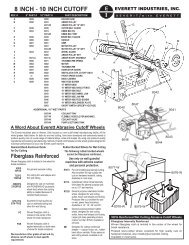
<strong>Operating</strong> <strong>Instructions</strong>FOR EVERETT 8˝ & 10˝ ABRASIVE CUTOFF MACHINESFORWARD<strong>Operating</strong> techniques outlined in the guide are basic. Skill and techniques develop as the operator gains knowledge of the cutoffmachine.Your safety and the safety of others depends upon care and judgment in the operation of this machine. A careful operator is goodinsurance against an accident.Most accidents, no matter where they occur, are caused by someones failure to observe and follow simple and fundamental rulesor precautions. For this reason most accidents can be avoided by recognizing hazards and taking steps to avoid them before anaccident occurs.Regardless of the care used in the design and construction of any type of equipment, there are conditions that cannot becompletely safeguarded against without interfering with reasonable accessibility and efficient operation.This information is not intended to cover all possible operating conditions. The user should contact <strong>Everett</strong> <strong>Industries</strong> in the eventoperating conditions or situations are encountered which are not dealt with in these operating instructions.SAFETY INSTRUCTIONSAmerican National Standards Institute, ANSI, Safety Code Number B7.1 is the approved safety code for the use, care andprotection of abrasive wheels according to the Occupational Safety and health Administration, (O.S.H.A.), U.S. Department ofLabor. Everyone using abrasive wheels and machinery must be familiar with this code and fully comply with it to insure againstunsafe working conditions.1. READ MACHINE OPERATING INSTRUCTIONS. NEVER START MACHINE WITHOUT COMPLETE UNDERSTANDINGOF ITS OPERATION.2. USE REINFORCED WHEELS ONLY.3. RING TEST AND INSPECT EACH WHEEL BEFORE INSTALLING. DO NOT USE WHEEL IF CRACKED ORFRACTURED.4. WEAR FULL FACE SHIELD WHEN OPERATING MACHINE.5. MAKE SURE ALL SAFETY GUARDS ARE IN PLACE BEFORE STARTING MACHINE.6. MAKE SURE WORK PIECE IS HELD FIRMLY IN VISE BEFORE STARTING MACHINE.7. OPERATE WITHIN RATED MACHINE CAPACITY.8. DO NOT OVER FEED CUTOFF WHEELS.9. NEVER USE CUTOFF WHEELS FOR GRINDING.10. ALWAYS KEEP WHEEL GUARD IN DOWN POSITION EXCEPT WHEN CHANGING WHEEL.11. KEEP HANDS CLEAR OF CUTTING AREA.12. OBSERVE ALL COMMON SENSE SAFETY PRACTICES.13. SET UP MAINTENANCE PROCEDURES FOR CARE AND CLEANING OF MACHINE.14. COMPLY WITH ANSI SAFETY CODE B7.1.Applications for copies should be addressed to:American National Standards Inst. Inc.25 West 43rd Street 4th FloorNew York, New York 10036COMPLY WITH OCCUPATIONAL SAFETY AND HEALTH ADMINISTRATION (OSHA), U.S. DEPT. OF LABOR,(Standards are printed in the Federal Register) Applications for copies should be addressed to:U.S. Government Printing Office732 N. Capitol Street NWWashington, DC 20401FAILURE TO COMPLY WITH ANY OF THESE INSTRUCTIONSCAN RESULT IN SERIOUS BODILY INJURY.“WARRANTY: All <strong>Everett</strong> products are warranted against defective materials andworkmanship, conditioned as follows. If a product is returned to <strong>Everett</strong> by theoriginal purchaser prepaid within 1 year after delivery to the original purchaser andis judged by <strong>Everett</strong> to be defective, the product will be repaired, replaced orcredited. This warranty is exclusive and in lieu of all other warranties of quality,whether written, oral, or implied (including any warranty of merchantability orfitness for purpose). <strong>Everett</strong> will not be liable for any consequential damages andno claims will be allowed for repairs to <strong>Everett</strong> products by the purchaser orany third party.”SETTING UP MACHINESAll machines should be leveled and secured to work stand or table.ELECTRICAL CONNECTIONSAll electrical connections should be made by an experienced electrician inaccordance with all applicable local and national electrical codes.GROUNDING INSTRUCTIONS1. All grounded, cord connected tools:In the event of a malfunction or breakdown, grounding provides a path of leastresistance for electric current to reduce the risk of electric shock. This tool isequipped with an electric cord having an equipment-grounding conductor anda grounding plug. The plug must be plugged into a matching outlet that isproperly installed and grounded in accordance with all local codes andordinances.Do not modify the plug provided – if it will not fit the outlet, have the properoutlet installed by a qualified electrician.Improper connection of the equipment-grounding conductor can result in a riskof electric shock. The conductor with insulation having an outer surface that isgreen with or without yellow stripes is the equipment-grounding conductor. Ifrepair or replacement of the electric cord or plug is necessary, do not connectthe equipment-grounding connector to a live terminal.Check with a qualified electrician or service personnel if the groundinginstructions are not completely understood, or if in doubt as to whether the toolis properly grounded.Use only extension cords that have grounding plugs and receptacles thataccept the tools plug.Repair or replace damaged or worn cord immediately.SINGLE PHASEIf your new unit is wired for operation on 110 volt single phase, you mustinstall adequate fuses in your electrical system to avoid blowing a fuse whenthe machine is first started. We recommend delayed action, “Fusetron” type,rated for 40 amps.If your unit is wired for 220 volt, single phase, use delayed action fuses ratedfor 20 amps.Voltage changes can be made as diagramed on the motor nameplate.If your machine slows down or stalls, check your voltage and make certain yourwire is heavy enough. A long extension cord or wires that are too small willreduce the motor power. Wires should be at least #10 or larger.Remove wheel nut and flange before testing for rotation. After connectingpower line, check the direction of spindle rotation. It should be counterclockwisestanding on the right side of the machine. If it is rotating clockwise,interchange any two sets of leads. (SEE MOTOR NAMEPLATE IF SINGLEPHASE).OPERATION1. Secure workpiece in vise.2.After slowly making contact between wheel and material, apply steadyeven pressure until the cut is complete.Discoloration on dry cuts may indicate a cutting speed that is too slow ora wheel grade that is too hard. For wet cuts, discoloration may indicatecutting too fast for a wheel grade that is too hard.CAPACITYDo not exceed machine capacity:8˝ Machine • 1˝ Solids, 1-1/2˝ Pipe • 10˝ Machine, 1-1/2˝ Solids, 2˝ PipeDRY CUTTING — USING THE PROPER WHEELAlways use <strong>Everett</strong> fiberglass reinforced cutoff wheels. <strong>Everett</strong> wheels aredesigned especially for <strong>Everett</strong> abrasive cutoff machines — “Sever it with<strong>Everett</strong>” — to get longer wheel life and quality cuts. Machine warranty valid if<strong>Everett</strong> wheels are used. EVERETT WHEELS ARE PRICED LOWER, LASTLONGER, CUT BETTER. For cutting ferrous materials — iron, steel, etc., usethe <strong>Everett</strong> #45FG internally reinforced or the <strong>Everett</strong> #45FGE externallyreinforced wheel for all general purpose cutting. This wheel grade is the resultof thousands of test cuts and will assure you of economical and efficient cutson pipe, angle, channel, solids, stainless, etc.DRY CUTTING SPEEDSFast cutting will insure maximum wheel life and cleaner cuts. Dry cutting timeshould be approximately 5 seconds per square inch of material cut.FORM 3/06P.O. Box 20683601 Larchmont Avenue • Warren, Ohio 44484info@everettindustries.com • www.everettindustries.comPhone: (330) 372-3700 • Toll Free (800) 637-7297 • Fax: (330) 372-3118WET CUTTINGBecause most wet cutting wheels cannot be reinforced, use them withextreme caution on well guarded machines. OTHER WHEEL GRADESARE AVAILABLE FOR PARTICULAR APPLICATIONS.WET CUTTING SPEEDSBecause wet cutting is primarily recommended for quality of cut, rather thanspeed, slower wheel feeds MUST be used. Wet cutting speeds may varydepending on machine horsepower, wheel grade, material shape andhardness, and wheel feed.
<strong>Operating</strong> <strong>Instructions</strong>FOR EVERETT 12" to 26" ABRASIVECUTOFF MACHINESFOREWORD<strong>Operating</strong> techniques outlined in this guide are basic. Skill andtechniques develop as the operator gains experience with the cutoffmachine.Your safety and the safety of others depends upon care and judgementin the operation of this and all machines. A careful operator is goodinsurance against an accident.Most accidents, no matter where they occur are caused by someone’sfailure to observe and follow simple and fundamental instructions andprecautions. For this reason most accidents can be avoided byrecognizing hazards and taking steps to avoid them before an accidentoccurs.Regardless of the care used in the design and construction of any typeof equipment, there are conditions that cannot be completely safeguardedagainst without interfering with reasonable accessibility andefficient operation.The material contained in this booklet is not intended to cover allpossible operating conditions. The user should contact <strong>Everett</strong> <strong>Industries</strong>in the event operating conditions or situations are encounteredwhich are not dealt with in these operating instructions.SAFETY INSTRUCTIONSObserve American National Standards Institute, A.N.S.I., Safety CodeNumber B11.9-1975 “Safety Requirements For The construction, Careand Use of Grinding Machines” and B7.1- 2000. “Safety Code For TheUse, Care And Protection of Abrasive Wheels”, as well, which isincluded in Occupational Safety and Health Act, O.S.H.A. regulations.Copies of the A.N.S.I. standards may be purchased fromAmerican National Standards Institute25 W. 43rd St., Fourth FloorNew York, NY 10036Everyone using abrasive wheels and machines must be familiar withthese instructions and fully comply with the above and any otherapplicable safety codes for safe operation.1. READ MACHINE OPERATING INSTRUCTIONS. NEVER STARTMACHINE WITHOUT COMPLETE UNDERSTANDING OF ITSOPERATIONS.2. USE ONLY REINFORCED ABRASIVE CUT-OFF WHEELS.3. RING TEST AND INSPECT EACH WHEEL BEFORE INSTALLING.DO NOT USE WHEEL IF CRACKED OR FRACTURED.4. WEAR FULL FACE SHIELD WHEN OPERATING MACHINE.5. BE SURE ALL SAFETY GUARDS ARE IN PLACE BEFORESTARTING MACHINE.6. BE SURE WORK PIECE IS HELD FIRMLY IN VISE BEFORESTARTING MACHINE.9. NEVER USE SIDE OF CUTOFF WHEELS FOR GRINDING.10. ALWAYS KEEP WHEEL GUARD IN DOWN POSITION.11. KEEP HANDS CLEAR OF CUTTING AREA.12. OBSERVE ALL COMMON SENSE SAFETY PRACTICES.13. SET UP MAINTENANCE PROCEDURES FOR CARE ANDCLEANING OF MACHINE. OBSERVE LOCK-OUT/TAG-OUT PROCE-DURES FOR MAINTENANCE AND WHEEL CHANGES.14. COMPLY WITH A.N.S.I. SAFETY CODE B7.1 2000, A.N.S.l. B 11.9-1975, O.S.H.A. and all other applicable safety codes and regulations.O.S.H.A. regulations are printed in the CODE OF FEDERAL REGULA-TIONS, TITLE 29-LABOR, PARTS 1900 thru 1910. Copies of the federalregulations can be purchased from;U.S. Government Printing OfficeSuperintendent of DocumentsWashington, D.C. 20402FAILURE TO COMPLY WITH ANY OFTHESE INSTRUCTIONS CAN RESULT INSERIOUS BODILY INJURY.SETTING UP MACHINESAll machines should be leveled and secured to work stand or floor.ELECTRICAL CONNECTIONSAll electrical connections should be made by a licensed electrician inaccordance with all applicable local, state and national electrical codes.Remove wheel nut, and flange before testing for rotation. Observelockout-tagout during this test. After connecting power to the controlpanel or starter, check the direction of spindle rotation. Rotation shouldbe counter-clockwise standing on the right side of the machine. If it isrotating clockwise, interchange any two sets of leads. (SEE MOTORNAMEPLATE IF SINGLE PHASE).DRY CUTTING --USING THE PROPER WHEELAlways use <strong>Everett</strong> fiberglass reinforced cutoff wheels. <strong>Everett</strong> wheelsare designed especially for <strong>Everett</strong> abrasive cutoff machines -- “Sever itwith <strong>Everett</strong>” -- to get longer wheel life and quality cuts. EVERETTWHEELS ARE PRICED LOWER, LAST LONGER, CUT BETTER. Forcutting ferrous materials -- iron, steel, etc., use the <strong>Everett</strong> #45FGinternally reinforced or the <strong>Everett</strong> #45FGE externally reinforced wheelfor all general purpose cutting. This wheel grade is the result ofthousands of test cuts and will assure you of economical and efficientcuts on pipe, angle, channel, solids, stainless, etc..DRY CUTTING SPEEDSFast cutting will insure maximum wheel life and cleaner cuts. Dry cuttingtime should be approximately 5 seconds per square inch of material cut.WET CUTTINGBecause most wet cutting wheels cannot be reinforced, use themwith extreme caution on well guarded machines. OTHER WHEELGRADES ARE AVAILABLE FOR PARTICULAR APPLICATIONS.Wet Cutting time should be approximately 30 seconds per square inchof material cut. Contact the factory for wheel grade recommendations.7. OPERATE WITHIN RATED MACHINE CAPACITY.8. DO NOT OVER FEED CUTOFF WHEELS.REVISED 4/07
WET CUTTING SPEEDSWet cutting is primarily recommended for quality of cut, rather thanspeed. Slower wheel feeds MUST be used. Wet cutting speeds mayvary depending on several factors, including, horsepower, wheelgrade, material composition, shape, hardness, oscillation and wheelfeed. We recommend a starting speed of approximately 30 secondsper square inch of material cut. Use this reference speed as a startingpoint and adjust this speed to your conditions.COOLANT SUPPLYFOR WET MACHINES1. The coolant tank and pump are shipped on a separate skid from themachine. After unpacking, place the pump and tank on the floor on theright side facing the machine, with the pump to the front. (Exception -place them on the left side of a 20"-22" Wet Mitering machine). A wiring“harness” is provided and is wired into the electrical control panel. Theuser MUST make final electrical connection between the “harness” andthe coolant pump motor. After the electrical connection is made, makesure rotation of pump motor is correct (A directional arrow is provided).Interchange any two sets of leads if it is not. Also connect the hosefrom the pump to the control valve on the machine and tighten thehose clamp.2. It Is essential that coolant applied during wet cutting be directed toboth sides of the cut in equal volume, otherwise the wheel will wearunevenly, leaving a chisel-like cutting edge on the wheel, causing it to“lead off” in the cut, or possibly break.3. On 20"-22" and 26" Wet Machines equipped with a water box, adjustthe two hinged sides of the water box approximately 1/8” from wheel(roughly the thickness of a wheel) so coolant is equally distributed oneach side of the wheel, adjust if necessary.OPERATING YOUR EVERETT ABRASIVECUTOFF MACHINE1. Observe all lockout-tagout and safe operating practices whileinstalling or changing wheels.2. To install wheel, raise or open wheel guard and remove arbor nutand flange with supplied wrench. Inspect wheel before placing wheelon arbor shaft and replace flange and arbor nut. Hold wheel with lefthand and tighten nut with wrench using a quick jerking motion to setthe nut. Lower or close and lock wheel guard.3. 26" machines are equipped with a “drive pin” in the outer flange.The drive pin helps prevent wheel slippage should the machineoperator not tighten the arbor nut securely. The inner flange has arecessed hole to receive the drive pin. To install 26” wheel, placewheel on arbor shaft and visually line up drive pin hole in the wheelwith recessed drive pin hole in inner flange. Then replace outer flange,making sure the drive pin goes into the drive pin hole -in the wheel andrecessed hole in flange. Prior to tightening arbor nut, make sure thedrive pin is in contact with the drive pin hole in the wheel to insureagainst slippage, by rotating wheel clockwise until contact is made.Tighten arbor nut, close and lock wheel guard door.4. Adjust down stop so that wheel passes thru wheel slot in vise butdoes not touch the bottom of the vise. The wheel, if allowed to touchthe vise, will cut the vise as easily as it cuts your material. Lower thestop as wheel wears.5. When holding material in the vise it is very important that thematerial does not move while being cut. Keep steady pressure on thevise until cut is completed and the wheel is returned to full up position.When cutting long lengths use an <strong>Everett</strong> outboard support to keep thematerial level with vise. CAUTION: DO NOT ALLOW THE WORKSUPPORTS TO RAISE THE MATERIAL ABOVE VISE HEIGHT. Thiscondition can cause the material to pinch and break the wheel.This shows improper distribution of coolant supplywheel wears unevenly -- cuts lead off to one side.The <strong>Everett</strong> adjustable outboard support is an easy,inexpensive way to support long lengths of materialsto be cut.Ball-bearing rollers, set at the same angle as our ‘V’vise, eliminate the need to readjust for cuttingdifferent shapes.When coolant is directed evenly on both sides of the wheel, edgeremains square and makes square cuts.4. On the 14"-16" Wet Machine and 20"-22" Wet Mitering Machine,water is supplied to each side of the wheel using an adjustablemanifold. Proper flow adjustment is essential to quality cuts.5. A rust inhibitor only should be added to the coolant system. Werecommend using FUCHS# 2001. The correct mixture for abrasivecutting is 100 parts water to one (1) part rust inhibitor. A ‘start-up’supply has been included with your machine. Fill the tank with waterand add the rust inhibitor. Make sure the discharge hose is directedfrom the coolant pan into the coolant tank. Coolant made for use onmilling machines or band saws is not recommended because itwill cause wheel loading, heat buildup, poor cuts and wheelbreakage.NON FERROUS CUTTINGFor cutting non ferrous materials — we recommend a steel blade withan oil mist spray lubricant for thin wall cross sections (this optionalaccessory can be furnished on most saws) and flood coolant for heavycross sections.A unique slotted sleeve and locking handle preventsscoring the adjustable height shaft when locking inplace.6. To start your cut, bring cutting wheel onto the material gradually andapply steady even pressure until the cut is complete. Recommendedcutting speeds to start are 5 seconds per square inch of material drycutting, and 30 seconds per square inch wet cutting.FREE CONSULTATION SERVICEThe factory can advise proper techniques, wheel grades and otherinformation made available over more than 40 years of experience.Please feel free to take advantage of this service.WHEEL STORAGEStore wheels flat in a cool, dry location on a hard flat surface — neverstore on edge.MAINTENANCE“Common Sense” maintenance is all your new <strong>Everett</strong> cutoff machineshould need. Keep it clean, including the inside of the wheel guard,
spark guards, and cabinet base. Check for worn or damaged parts, i.e.,when changing the wheel, check the flanges for wear as well as“scoring” or “under cutting” of arbor shaft. Check vise, making sure it’snot cut in two, causing possible tolerance and safety problems. If partsare worn or damaged, timely replacement will insure safe, efficient, longterm operation of your machine.WHEEL LOADINGWheel LOADING is a problem that can affect the outcome of allabrasive cutoff applications, wet or dry. It occurs when metal particlesfrom the material being cut adhere to the cutting edge of the wheel,even though the machine spindle speed and horsepower, cutting speedand wheel grade, have been taken into account. Once started, thisloading process usually gets worse rather than better, and can lead to anumber of additional, unwanted results if nothing is done to DRESS (orunload) the wheel.The first of the “unwanted results” to be noticed is a lot of smoke,followed by burned, crooked cuts, pinched or broken wheels, and unduestrain on the belts, arbor bearings and motor. At this point, the machineis most often blamed for all these problems, when in fact, it is a loadedwheel.The SOLUTION to this problem is, in fact, quite simply to DRESSTHE WHEEL! How is this accomplished? Place a piece (or pieces) ofused broken up wheel securely in the vise, and then carefully and slowlybring the loaded wheel into contact with this FREE wheel dresser untilthe loading is gone and a brand new cutting edge is present, (in effect anew wheel). Or, as an alternative, purchase a vise mounted diamondwheel dresser, and dress the wheel, carefully using the proceduredescribed above.Once the wheel is dressed, and the basic operating and cuttinginstructions are followed, cooler, cleaner, quality cuts will result.<strong>Operating</strong> <strong>Instructions</strong>MACHINES EQUIPPED WITH OSCILLATION1. The oscillation feature moves the wheel back and forth while cut isbeing made, reducing the area of contact between wheel and material,This results in improved quality of cut, less heat buildup, less burr andincreased wheel life.2. Oscillation is controlled by a three position selector switch L locatedon the push button control station marked “OSCILLATION”, “OFF”,“AUTO”, “ON”. For “AUTOmatic” operation, that is the oscillator turns onand off with the main motor, turn the selector knob L to the center. For“HAND” or manual on-off operation, turn the selector knob L to the right.The left position is “OFF”.NOTE: If the wheel wedges in the cut it is sometimes possible torelease the wheel by moving to the “HAND” operation on the selectorswitch and raising the wheel to the up position without the main drivemotor running.3. The oscillation motor (part 12638) is a 1/3 H.P. gearmotor. It is filledwith 9OW gear oil. Use any high quality SAE 90 oil if required.4. If the wheel loads up, you are either feeding too slow, have too muchcoolant, the wrong type of coolant (see COOLANT SUPPLY FOR WETCUTTING), or too hard of a wheel. A loaded wheel cutting Wet can bedressed by turning the water off for a few seconds while cutting in orderto dress the wheel.HYDRAULIC POWER HEAD MACHINESCAUTION: DOUBLE CHECK ARBOR SHAFT ROTATION (counterclockwise) from flange end before proceeding with the check list below,with wheel, outer flange, and arbor nut removed from arbor shaftjog Start Stop Button J on then off, and visually observe direction.Change any 2 sets of leads if rotation is not counter clockwise.CAUTION: MAKE DRY RUNS WITH NO MATERIAL IN VISE ANDMOTOR OFF. (Do not touch Start Stop Button J until all adjustments aremade.)CHECK SAW ACTION WITH CHECK LIST BELOW1. Install wheel on arbor shaft - according to instructions on previouspage.FEED SPEED CONTROL VALVE C IS LOCATED AT TOP FRONT OF ROCKERARM ON 16 & 20 DRY MACHINE.2. Start hydraulic pump by turning switch T “ON”, if wet machine turnswitch to “HYD” position. This will start hydraulic pump only, coolant isnot wanted at this time.3. Turn “FEED SPEED CONTROL VALVE” C full counter clockwise,Push “HEAD UP-DOWN” switch E “DOWN” , allowing wheel to move ina downward direction. Control down speed by adjusting “FEED SPEEDCONTROL VALVE” C. Allow wheel to slowly proceed down until itcomes to about 1/8” to 1/16” of reaching bottom of the vise. Stopdownward travel by pushing “HEAD STOP” button F. Do this quickly toprevent possible damage to vise and wheel.4. Manually adjust DOWN STOP SCREW up until “DOWN STOP LIMITSWITCH” U is activated. This adjustment will energize the up hydraulicsolenoid and automatically reverse the motion, sending the wheel in theupward direction. Upward motion can also be achieved by pushing“HEAD UP - DOWN” switch E “UP”.NOTE: The “DOWN STOP SCREW” adjustment must be made(lowering the screw) as wheel wears to compensate for its smallerdiameter and whenever a new wheel is placed on machine (raising thescrew to prevent cutting into the machine). If the machine is equippedwith an electronic wheel wear compensator, refer to operating instructionsfor compensator adjustment.5. When traveling up, the “UP-STOP LIMIT SWITCH” V is activated. Thehydraulic valve shifts to neutral and the upward travel stops. Movementof the head can be stopped at any time by pressing the “HEAD STOP”button.If the “UP - STOP LIMIT SWITCH” V is not positioned properly, thehydraulic cylinder may bottom out before the switch is activated, thevalve will not shift to neutral and the up solenoid may burn out andrequire replacement before the head can go up in the next cycle.NOTE: After dry runs are completed and the size material you arecutting has been selected, the “UP STOP LIMIT SWITCH” V may bemoved down to a point where the wheel clears the material you arecutting by a safe amount. This procedure eliminates “cutting air” andwaiting for the wheel to reach the work piece during each cycle.
6. Push “HEAD UP - DOWN switch” E “DOWN” and adjust “FEEDSPEED CONTROL VALVE” C to correct rate of feed. Use the rate of1 square inch of solid material in 5 to 8 seconds cutting dry. Go slowerif material has a tendency to discolor or burn, or if wet cutting using therate of 30 seconds per square inch.7. Now cycle machine through the cutting cycle several times to makesure all switches are functioning properly and that the wheel visuallytravels to proper depth to cut through material but not deep enough tocut into vise. This will also help you become familiar with controloperation.8. During these test runs push “HEAD STOP” button F while wheel istraveling to become acquainted with this built-in safety feature.Activating this button will shift the hydraulic valve to neutral and stopmotion. Also at any time during down stroke, you can reverse directionby pushing “HEAD UP - DOWN” switch E “UP”.TRIAL SETUPAfter setting the down stop, as described in the previous section, placea filler block in the vise but not extending into the wheel clearance slot.Next position and clamp some test material in the vise on top of the fillerblock, see drawing. The filler block will allow you to determine if thecompensator, is adjusted so that the wheel returns to the up positionafter completion of the cut. It wheel wear compensator is not properlyadjusted the down stop will return the head to the up position after thewheel travels the distance of the height of the filler block. Make a testcut to determine if the compensator is adjusted properly. If the headdoes not return automatically after completing the cut, manually movethe head to the “Up” position by pushing switch “E” to the “UP” position.Move the test piece over to make another cut, if the test material is asolid, fine tune compensator adjustment again. If the test material is“light” and the cut was not complete when the head returned up,increase the down speed slightly.YOU ARE NOW READY TO MAKE TEST CUTS. We suggest startingwith solid material 2" in diameter or smaller until everyone connectedwith the machine operation is familiar with all procedures.CLAMP MATERIAL SECURELY IN VISE,Energize: “HYDRAULIC PUMP” switch T“START and STOP” button J“HEAD UP - DOWN” switch Eand with “FEED SPEED CONTROL VALVE” C regulate down speed. Asthe wheel wears, it is necessary to readjust the “DOWN STOP SCREW”to allow the wheel to complete the cut. Remember to readjust “DOWNSTOP SCREW” up when replacing worn wheel.NOTE: Air trapped in any hydraulic system can cause erratic control. Ifyou suspect this to be a problem;1. Make sure hydraulic oil reservoir is full. (Use a high grade ISO 46hydraulic oil).2. Bleed air from system. To achieve this, first raise head to full upposition. Pull clevis pin keeper and clevis pin which disconnects thehydraulic cylinder rod from the base of the machine and unscrew clevisfrom cylinder rod. Then push “HEAD UP - DOWN” switch E, “UP”(retracting the rod into the cylinder) and then “DOWN” (extending therod out of the cylinder) several times, causing the cylinder rod to travelits full length of stroke in both directions. This should force any trappedair out of the system. It may be necessary to extend the cylindercompletely, close the “FEED SPEED CONTROL VALVE” C and cyclethe “HEAD DOWN” switch and loosen, just slightly, the hose fitting onthe top on the cylinder as the rod begins to retract until all air is out andthen retighten the fitting before oil leaks out. Extend the cylinder andwait a few moments while the air bubbles move to the top of the cylinderand repeat. Clean any oil that may have dripped before continuing.PRINCIPAL OF OPERATION OFTHE WHEELWEAR COMPENSATORThe electronic wheelwear compensator, located inside the electricalcontrol panel, monitors the electrical current used by the main drivemotor. As the cutoff wheel moves into the cut, current (load on motor)increases and “arms” the circuit. When the cut is complete the currentdrops back to its idle level. This charge triggers the compensator to shiftthe hydraulic valve to return the head to the up position.SETTING WHEELWEAR COMPENSATORUSE EXTREME CAUTION —LINE VOLTAGE IS PRESENT IN THECONTROL PANEL WHEN THIS ADJUSTMENT IS MADE.With the motor running adjust the knob on wheelwear sensor (insideelectrical panel marked “CURRENT LEVEL RELAY”) counter clockwiseuntil “Relay On” light comes on. Now slowly turn the knob clockwise untilthe light just goes out. The compensator is adjusted before it leaves thefactory; however, you may have to “fine tune” this setting.OPERATION OF WHEELWEARCOMPENSATORIf you are cutting small cross sectional areas, the change in load maynot be sufficient to operate the compensator circuit. It is possible onsome cuts to “fine tune” the compensator by adjusting the knobclockwise slightly to just before the light comes on. If the light shouldcome on, rotate the knob counter clockwise again and repeat. It is alsopossible to increase the load on the motor by increasing the cuttingspeed (the speed that the head moves down).WHEELWEAR COMPENSATORAND OSCILLATIONMachines with oscillation also have a timer in the compensator circuit.With the oscillation turned on, the load on the motor constantly variesand sometimes the wheel is completely out of the cut bringing thecurrent back to the “idle load” level. This would normally trigger thewheelwear compensator circuit and cause the head to return to the upposition. The timer delays the response time from when the “idle” isdetected until the head starts moving up.The timer is adjustable to allow for various down feed speeds and topermit the cut to be completed without the wheel cutting into the vise.USE EXTREME CAUTION -- LINE VOLTAGE IS PRESENT IN THECONTROL PANEL WHEN THIS ADJUSTMENT IS MADE. As downspeeds increase the timer setting should he decreased. If not, thecompensator will detect cut completion but the timer will delay theresponse of the head returning up by up to 3 seconds.Proper adjustments of the compensator is a correlation of:material being cut speed of cutshape of material setting of timerload on the motor oscillation on or off
Arbor Shaft Assembly and/or BearingReplacement <strong>Instructions</strong>TO REMOVE ARBOR SHAFT & BEARINGS OBSERVE LOCKOUT —TAGOUT REQUIREMENTS.1. Remove belt guard. Draw a line along the front of the motor baseplate. This will serve as an alignment reference later. Loosen motormounts and jackscrews. Remove belts.2. Remove Pulley by:a. Removing the 3 bolts in pulley bushingb. Place these bolts in the tapped holes of the bushing and tightenevenly. This will push the pulley towards the rocker arm and offthe taper lock bushing.c. When the pulley is completely free of the bushing,remove the 3 bolts.d. Remove the bushing by placing a screwdriver in theslot of the bushing and gently tap the screwdriver inuntil the bushing spreads open just enough to slidethe bushing off of the arbor shaft, remove key.e. Remove pulley spacer and save it.f. Remove bearing keeper bolt located an flange side ofthe rocker arm (on 26” machine only).3. Remove arbor shaft by driving left to right.TO INSTALL NEW ARBOR SHAFT & BEARINGS1. Make sure rocker arm is free of abrasive dust, chips and other debrisin the bearing seats and arbor area.2. With a soft hammer or wood block to protect it, install new bearing inpulley side of rocker arm. Fit should be easy but not sloppy.3. Again check that no contamination is in the bearing area and installarbor shaft, checking alignment when the shaft enters the oppositebearing.4. With a soft hammer gently tap the arbor shaft (not flange) into therocker arm partially.INSTRUCTIONSREPLACING SPINDLE10. Place pulley bushing on arbor against pulley spacer. Mark the arborshaft to indicate how far on the arbor the bushing must go to be againstthe pulley spacer. Accurately measuring the distance from pulleybushing to the end of the arbor shaft is another acceptable method toinsure proper repositioning of the bushing. With contact between theinner race and the spacer, and the spacer and the pulley bushing, lockthe arbor shaft in place preventing the shaft from moving left to right andhelping maintain straight cuts.11. Place pulley bushing into pulley. Install 3 bolts into “Clearance” holesof bushing and tapped holes of pulley. (This may be reversed on somemachines, clearance in pulley, tapped holes in bushing).12. Place pulley assembly onto arbor shaft. Be certain bushing is up toyour mark on shaft and insure bushing is against spacer (or measureddistance is arrived at again).13. Remove screwdriver and evenly tighten bolts. As bolts aresnugged:a. Place a straight edge against pulley and pick areference point on motor pulley.b. Rotate arbor 1/3 turn and check with straight edgeand reference.c. Repeat again another 1/3 revolution.d. Tighten appropriate bolts to true pulley with arborshaft.Proper approximate torque on pulley bolts.Up to 20" Machine 9 FT/lbs.26" Dry Machine 30 FT/lbs.26" Wet Machines 60 FT/lbs.14. Motor pulley and arbor pulley should now be running true with theirrespective shafts. Install belt(s).15. Position motor so that a straight edge on arbor pulley is parallel withbelts.16. Using jackscrews, tension belt(s). Be certain pulleys remain paralleland use a straight edge to keep pulleys in the same plane so that thebelt will track properly. The reference line drawn in Step 1 may be usedas a “Guide” for belt tension and parallelism between arbor shaft &motor shaft. For “V” belts, tension should be measured as a deflectionof about 1/64”, times the center distance between the shafts, with a2 1/2 pound force between centers ON ONE BELT ONLY.17. Replace belt guard. Do not use bolts longer than 1/2 inch or belt(s)will be cut by bolt.18. Check belt tension after approximately 8 hours use. Make surebelt(s) and pulley run true with motor and arbor shaft, and motor shaftand arbor shaft are parallel.5. Place a pipe slightly larger than the arbor shaft, over the pulley end ofthe shaft and against the inner race of the bearing.6. Have someone “buck” against the flange end of shaft while thebearing on the pulley side is being tapped in place. Using the pipe and asoft hammer, if necessary, tap the arbor shaft assembly back into therocker arm.7. Repeat Step 6 until arbor shaft is completely installed, with bothbearings against the bearing stops . (Bearing stops on 26” shaft only).8. Replace bearing keeper bolt (on 26" machine only).9. Install pulley spacer against bearing and tighten set screw.Install key.
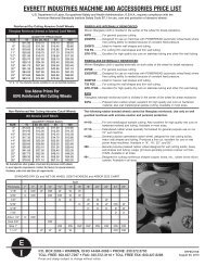
A WORD ABOUT EVERETTABRASIVE CUTOFF WHEELSThe <strong>Everett</strong> <strong>Industries</strong> plant in Warren, Ohio houses our owncutoff wheel manufacturing facility. All the wheel grades listedbelow, for both dry and wet cutting have been developed andextensively tested to produce quality cuts on a wide range ofmaterial alloys, sizes and shapes. By using only premium qualityingredients and exacting manufacturing methods, <strong>Everett</strong> cutoffwheels provide wheel grades designed for maximum performanceon your new <strong>Everett</strong> cutoff machine.RESINOID BOND ALUMINUM OXIDEFOR DRY CUTTINGFIBERGLASS REINFORCED - WOVEN FIBERGLASS CLOTHIS MOLDED IN THE WHEEL FOR BREAK RESISTANCE.45FG45 FGE}For general purpose cuttingT32 FGT32 FGE23020FG23020FGEGTK-7FGGTK-7FGEFGFGE}}}}}For cutting thin wall shapes and thin wall tubingDesigned for use on machines with POWERHEAD(automatic wheel feed) where free cutting ability isneeded because of constant feed pressureExcellent for high quality dry cuts on stainless tubingand other thin wall tubingWoven fiberglass cloth is molded in the center of thewheel for break resistanceWoven fiberglass cloth is applied externally on bothsides of wheel for break resistanceWE MANUFACTURE OTHER GRADES OF WET AND DRY ABRASIVECUTOFF WHEELS TO MEET SPECIFIC REQUIREMENTS.RUBBER BONDED WHEELS FOR WET CUTTINGTHE FOLLOWING RUBBER BONDED WHEELS CANNOT BEFIBERGLASS REINFORCED#1410 For wet metallurgical sample cutting. Also excellent for highquality wet cuts on hardened material and tubing. Available inmost sizes.#1115 Calendered rubber wheel specially formulated for generalpurpose use on our 10" wet machine.#1329 General purpose calendered rubber wheel, designed for wetcutting solids, heavy wall shapes and tubing. Produces finecut, excellent for use on wet, power head machines. Availablein 14", 16", 20" and 26".#60 General purpose pressed rubber wheel, designed for wet cuttingsolids, heavy wall shapes and tubing. Larger grit sizes generallyproduce coarser cut than #1329. Available in all sizes.#91 Designed for cutting nonferrous shapes - copper, brass, etc.,rubber bond silicon carbide. Prices same as wet cuttingwheels. Available in all sizes.Use only on well guarded machines withextreme caution and personal protection.Warranty“All <strong>Everett</strong> products are warranted against defective materials and workmanship,conditioned as follows. If a product is returned to <strong>Everett</strong> by the original purchaserprepaid within 1 year after delivery to the original purchaser and is judged by <strong>Everett</strong>to be defective, the product will be repaired, replaced or credited. This warranty isexclusive and in lieu of all other warranties of quality, whether written, oral or implied(including any warranty of merchantability or fitness for purpose). <strong>Everett</strong> will not beliable for any consequential damages and no claims will be allowed for repairs to<strong>Everett</strong> products by the purchaser or any third party.”93FGREINFORCED WET CUTTINGABRASIVE CUTOFF WHEELSFiberglass Internally ReinforcedWoven fiberglass cloth is molded in the center of thewheel for break resistance.Pressed resin-rubber wheel; excellent for highquality cuts on hardened material, alsometallurgical sample cutting. Available in mostsizes.3601 Larchmont N.E. • Warren, OH 44483 • Phone: 330-372-3700 • Toll Free: 800-637-7297 • Fax: 330-372-3118info@everettindustries.com • www.everettindustries.com