Aqua-Swirl⢠Sizing Charts
Aqua-Swirl⢠Sizing Charts
Aqua-Swirl⢠Sizing Charts

Create successful ePaper yourself
Turn your PDF publications into a flip-book with our unique Google optimized e-Paper software.
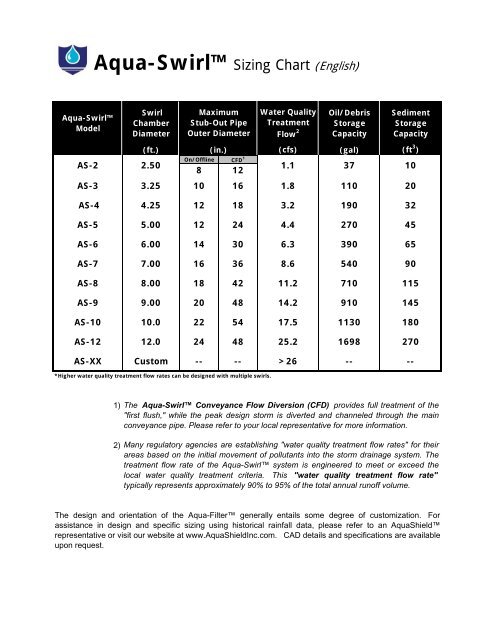
<strong>Aqua</strong>-Swirl <strong>Sizing</strong> Chart (English)<strong>Aqua</strong>-SwirlModelSwirlChamberDiameterMaximumStub-Out PipeOuter DiameterWater QualityTreatmentFlow 2Oil/DebrisStorageCapacitySedimentStorageCapacity(ft.) (in.)(cfs) (gal) (ft 3 )On/Offline CFD 1AS-2 2.508 121.1 3710AS-3 3.25 10 16 1.8 110 20AS-4 4.25 12 18 3.2 190 32AS-5 5.00 12 24 4.4 270 45AS-6 6.00 14 30 6.3 390 65AS-7 7.00 16 36 8.6 540 90AS-8 8.00 18 42 11.2 710 115AS-9 9.00 20 48 14.2 910 145AS-10 10.0 22 54 17.5 1130 180AS-12 12.0 24 48 25.2 1698 270AS-XX Custom -- -- >26 -- --*Higher water quality treatment flow rates can be designed with multiple swirls.1)2)The <strong>Aqua</strong>-Swirl Conveyance Flow Diversion (CFD) provides full treatment of the"first flush," while the peak design storm is diverted and channeled through the mainconveyance pipe. Please refer to your local representative for more information.Many regulatory agencies are establishing "water quality treatment flow rates" for theirareas based on the initial movement of pollutants into the storm drainage system. Thetreatment flow rate of the <strong>Aqua</strong>-Swirl system is engineered to meet or exceed thelocal water quality treatment criteria. This "water quality treatment flow rate"typically represents approximately 90% to 95% of the total annual runoff volume.The design and orientation of the <strong>Aqua</strong>-Filter generally entails some degree of customization. Forassistance in design and specific sizing using historical rainfall data, please refer to an <strong>Aqua</strong>Shieldrepresentative or visit our website at www.<strong>Aqua</strong>ShieldInc.com. CAD details and specifications are availableupon request.
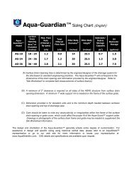
<strong>Aqua</strong>-Swirl <strong>Sizing</strong> Chart (Metric)<strong>Aqua</strong>-SwirlModelSwirlChamberDiameterMaximumStub-Out PipeOuter DiameterWater QualityTreatmentFlow 2Oil/DebrisStorageCapacitySedimentStorageCapacity(mm.) (mm.)(L/s) (L) (m 3 )On/Offline CFD 1AS-2 762203 30531140 0.28AS-3 991 254 406 51 416 0.57AS-4 1295 305 457 91 719 0.91AS-5 1524 305 610 125 1022 1.27AS-6 1829 356 762 178 1476 1.84AS-7 2134 406 914 243 2044 2.55AS-8 2438 457 1067 317 2687 3.26AS-9 2743 508 1219 402 3444 4.11AS-10 3048 559 1372 495 4277 5.10AS-12 3658 610 1219 713 6427 7.65AS-XX Custom -- -- >713 -- --*Higher water quality treatment flow rates can be designed with multiple swirls.1)2)The <strong>Aqua</strong>-Swirl Conveyance Flow Diversion (CFD) provides full treatment of the"first flush," while the peak design storm is diverted and channeled through the mainconveyance pipe. Please refer to your local representative for more information.Many regulatory agencies are establishing "water quality treatment flow rates" for theirareas based on the initial movement of pollutants into the storm drainage system. Thetreatment flow rate of the <strong>Aqua</strong>-Swirl system is engineered to meet or exceed the localwater quality treatment criteria. This "water quality treatment flow rate" typicallyrepresents approximately 90% to 95% of the total annual runoff volume.The design and orientation of the <strong>Aqua</strong>-Filter generally entails some degree of customization. Forassistance in design and specific sizing using historical rainfall data, please refer to an <strong>Aqua</strong>Shieldrepresentative or visit our website at www.<strong>Aqua</strong>ShieldInc.com. CAD details and specifications areavailable upon request.