Download - Moser Baer Solar Limited
Download - Moser Baer Solar Limited
Download - Moser Baer Solar Limited

You also want an ePaper? Increase the reach of your titles
YUMPU automatically turns print PDFs into web optimized ePapers that Google loves.
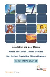
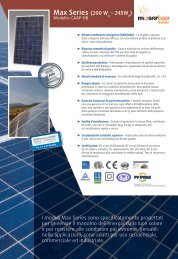
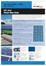
PLEASE READ THIS MANUAL CAREFULLY BEFORE INSTALLING ORUSING THE MODULESThis manual contains critical safety instructions for the PV module that must befollowed during the installation and maintenance of PV modules. Failure to followthese instructions may result in bodily injury or damage to property. Working on aphotovoltaic system requires specialized knowledge and should only be attemptedby qualified professionals.Introduction<strong>Moser</strong> <strong>Baer</strong> is a world leader in development and high-volume- manufacturing oftechnology products. Our prime commitment is to produce quality products that lastfor many years. <strong>Moser</strong> <strong>Baer</strong> PV modules are designed for versatility in application andsuited for residential, commercial and industrial applications.The modules use high efficiency Multi Crystalline silicon solar cells; high transmitivity,low iron content, tempered and toughened glass; and premium quality encapsulationmaterials having superior UV and thermal properties.Laminates are framed in anodized aluminium frames and come along with apermanently attached junction box with a 12AWG cable terminated in connectors.<strong>Moser</strong> <strong>Baer</strong> <strong>Solar</strong> <strong>Limited</strong>, IndiaDoc. No. PV/CN/ENG/WI/016,Rev No. 01, Rev. Date: 30/11/2010
Installation and User manual<strong>Moser</strong> <strong>Baer</strong> Max Series Photovoltaic ModulesModel : MBPV CAAP BB Wattage Range: 180 W-240WContents1. Warning Notice31.1 General safety 31.2 Handling safety 31.3 Installation safety 42 Mechanical Installation52.1 Site Selection 52.2 Tilt Angle Selection 52.3 Mounting Installation 62.3.1 General Installation 62.3.2 Ground Mounting 82.3.3 Roof mounting 92.3.4 Pole mounting 103 Electrical Installation103.1 Grounding Method 113.2 General Installation 124 Maintenance5 Module Specifications6 Product identification7 Disclaimer of Liability8 Notes14141616172
1.11. Photovoltaic modules can generate electricity upon exposure to light. The voltageof a single module is less than 45VDC, but the shock hazard increases as modulesare connected in parallel producing higher current. The shock hazard increasesas modules are connected in series producing higher voltages.2. All instructions should be read and understood before attempting to install, wire,operate, and maintain the photovoltaic module. Contact with electrically activeparts of the module such as terminals can result in burns, sparks, and lethalshock whether the module is connected or disconnected.3. Do not disconnect the connector of the modules while under load.1.2WARNING This indicates danger of death or serious bodily injury"CAUTION "This indicates danger of bodily injury or damage to property"WARNINGCAUTION1. To avoid the hazard of electric shock and injury, cover the entire front surface of thePV modules with a dense, opaque material such as a cardboard sheet, duringinstallation and handling of the modules.2. Do not hit or put excessive loads on the glass or back sheet or twist the frame, theglass may break, PV cells may break.3. Do not stand or step on the PV module, the glass may be slippery and there is arisk of injury or electric shock if glass breaks.4. PV modules are heavy , please handle with care. Do not drop or allow objects to fallon the PV module.5. Do not twist the interconnect cable excessively6. Unauthorized persons-except the qualified licensed professional--should notopen the cover of the junction box to avoid the hazard of electric shock. Providesuitable guards to prevent yourself from direct contact with 30 VDC or greater toavoid the hazard of electric shock or injury.7. When carrying a module, two or more people should carry it by its frame and wearnon-slip gloves (to avoid injury by a slipping module, to a foot, or cuts by the edgeof a frame, and so on).8. Do not lift the modules by grasping the module junction box or electrical cables.3
Installation Safety:WARNINGAll PV modules shall be installed in accordance with applicable codes andregulations, including but not limited in USA to National Electrical Code (NEC)and in Canada in accordance with CSA C22.1, Safety standard for electricinstallation, Canadian electrical Code (CEC).CAUTION1. Only PV modules with the same cell type and size should be connected in series2. Follow all safety instructions of other components used in the system3. Avoid uneven shade on the PV module surface .Shaded cells may become hot(hot spot phenomenon) which may result in permanent damage to the module.4. Do not drill holes in the frame, it may compromise the frame strength and causecorrosion of the frame also void the warranty.5. To avoid the hazard of electric shock, work only under dry conditions, with drymodules and tools.6. Do not puncture or damage the back-sheet of a module, to avoid the hazard ofelectric shock and fire.7. To avoid the hazard of electric shock and injury, be sure to completely ground allmodules & do not disassemble the module, or remove any part installed by themanufacturer.8. Since sparks may occur, do not install the module where flammable gases orvapors are present.9. Never leave a module unsupported or unsecured.10. Do not use mirrors or other magnification device to artificially concentrate sunlightonto the modules.11. Do not change the connection of bypass diodes to avoid the hazard of electricshock and injury.12. MBPV CAAP BB series of modules qualified for Application class A4
2 MECHANICAL INSTALLATION2.1 Site Selection:1. PV modules are intended for outdoor use only and should be installed in a locationwhere they will receive maximum sunlight throughout the year.2. In Northern latitudes, the modules would normally face true south & in theSouthern Latitudes, the modules should face north for optimum power output3. Avoid trees, buildings or obstructions which could cast shadows on the solarmodules especially during the winter months when the arc of the sun is lowest overthe horizon.4. <strong>Solar</strong> modules produce maximum power when they are pointed directly at the sun.5. For installations where the solar modules are mounted to a permanent structure,the solar modules should be tilted for optimum winter performance.2.2 Tilt Angle Selection :More sunlight per square foot falls on a perpenicular surface (90 deg to the suns ray isoptimal).Less sunlight falls on a vertical surface & horizontal surface.The module tilt angle is measured between the solar modules andthe groundSite Latitutde inDegrees 0° to 15° 15° to 25° 25° to 30° 30° to 35° 35° to 40° 40°Fixed tilt angle 15° same as latitude +5° latitude +5° latitude +5° latitude +5°latitude5
Latitude 10°15° 20° 25° 30° 35° 40° 45°Summer 12.71° 13.02° 13.34° 13.7° 14.08° 14.54° 15.02° 16.62°Winter 11.54° 11.24° 10.92° 10.58° 10.21° 9.80° 9.33° 8.76°2.3 Mounting Installation:General Installation1. Place the modules on top of the structure & mount it by using the pre-drilledelliptical mounting holes as shown below & fix it firmly on the structure using themounting hardware`s (M4 nuts & Bolts).2. Always select the length of mounting screw after considering a clearance of 5-10mm between the module back face & screw face to avoid any breakage ofmodule while tightening (as shown below).6
3. The support module mounting structure must be made of durable , corrosionresistant and UV resistant material.4. Modules should be firmly fixed in place in a manner suitable to withstand allexpected loads, including wind & snow loads. Determine wind loads for theinstallation site & consult it from safety departments for the specific requirements.5. All hardware like bolts, nuts & washers should be of stainless steel so as toeliminate the possibility of rust.6. The Open circuit Voltage exceeds the rated voltage. Take care that the opencircuit voltage multiplied by the number of modules in series is not higher than theMax. system voltage (IEC-1000V)7. Module mounting must use the pre-drilled mounting holes in the frame.8. Do not drill additional mounting holes on the frame & glass surface of the module.Doing so will void the warrantyGround Mount1. Select the lowest height of the structure to prevent the lowest height of the modulefrom being covered by snow for a long time in winter.2. In addition ensure that the lowest portion of the module is placed high enough so8
that it is not shaded by trees or plants and not damaged by sand or stone drivenby wind.3. The supporting frame/structure is used to mount modules at correct tilt angles.4. Clearance between the modules frame & the mounting surface is required toprevent the junction box from touching the surface & to allow cooling air tocirculate around the back of the module. This also allows any condensation ormoisture to dissipate.Roof Mount(Tilt Roof/Wall Installation)1. Roof mounted PV modules should be mounted on a fire resistant roof.2. Installation should be carried out in calm winds to prevent accident due to fall.3. Special construction or structures may be required to help provide properinstallation.4. Both roof construction and module installation design have an effect on the fireresistance of a building. Improper installation may contribute to fire hazards.Additional devices such as ground fault, fuses, and disconnects may berequired.9
5. Make sure that roof structure can support the installation load and might requireservice of professional installers.6. The modules should never be sealed to the mounting surface with sealant thatprevents the junction box from touching the surface & air from circulating underthe module. Leave atleast 4 inches of clearance between the roof & the moduleframe.7. "MBSL modules are rated for fire class C. Module need to be securely mounted onfire resistant roof & slope less than 5 in/ft. (127mm/305mm) required to maintain afire class C."Pole MountChoose a pole and module mounting structure that will withstand the expected snowand wind Loads3 ELECTRICAL INSTALLATIONSeveral modules are connected in series and then in parallel to form a PV array,especially for application with a high operating voltage.10
The DC electrical energy from a PV module may be also be converted to AC andconnected to a utility grid system. As local policies on connecting renewable energysystems to a grid may vary from region to region, please consult a qualified systemdesigner or integrator to design such a system. Permits are normally required to installsuch a system and the utility must formally inspect and approve such a system before itis connected to the grid.3.1 GroundingThe module frame must be properly grounded to avoid the hazards of electric shock orfire.MBSL array frame shall be grounded in accordancewith National Electric Code (NEC)Each framed module has two grounding holes in thelonger side frame rail, to connect a graoundingconductor to the module metal frameOption 1The grounding will be provided by fixing earthingcable with Hex Nut, Star Tooth Washer, Flat Washerand Hex Head Bolt (M3.5) as shown in the belowpicture. All the above mentioned groundinghardware should be of stainless steel to prevent thecorrosion "Recommended Torque 1.2 Nm to 1.8Nm"Option 2"Attach all module frames to an earth ground usingthe "Solklip" ground clip (manufactured by TYCO).Attach the "Solklip” ground clip to one of thegrounding holes on the module frame with a screw(Provided in the Solklip)If functional grounding is used (i.e. grounding plus ofminus), such grounding means should be isolated fromlive parts by reinforced insulation102 mmGround"Use uncoated, solid copper in the 10 and 12 AWGwire sizes.”11
1. The facility electrical ground system must efficiently dissipates lightning surgeenergy that may arrive via down conductors of the lightning protection system andbe electrically and mechanically robust to assure performance over the "life" off thefacility.(Type USE-2, rated 90°Cwet or dry, 1000V 12AWG 4mm2 double insulated, halogenfree UV resistant solar cables Resistance to UV, water, ozone, fluids, salt and againstgeneral weathering, Resistance to abrasion.12
2. All wiring should be done in accordance with applicable electrical codes.3. Wiring methods should be in accordance with the electrical standards & norms ofthe country in which the modules are being installed.4. Wiring should be done only by a qualified & certified professional.5. Do not cut the connectors or crimp any other thimble on module wiring (Doing sowill void the warranty).6. The junction box, present on the back side of the module is designed to be usedwith standard wiring.7. The junction box has a breather port and the breather port must not be exposed todirect rain/water. Hence the Junction box should be mounted on the higher side ofthe module when mounted with the cable outlet pointing downward, preferably.8. The maximum electrical rating of an acceptable series fuse is 15 amperes.9. Keep in mind to follow the applicable codes for outdoor installation of wires inconduits. Verify that all fittings are properly installed to protect wire againstdamage & prevent moisture intrusion.10. Number of module in series connection should not increase such that voltagegenerated is beyond system voltage. Do not connect the modules in parallelwithout maximum over current protection.11. Blocking Diodes ;Blocking diodes can prevent night time battery discharging andalso prevent modules from loss of array output and damage by reverse currentflow. <strong>Moser</strong> <strong>Baer</strong> PV modules do not contain blocking diodes when shipped fromthe factory however most battery charge regulators do have this feature.12. By Pass Diodes ; In systems with modules in series strings, high reverse currentcan flow through cells that are shaded partially or when part of a module isshaded and rest is exposed to the sun. These currents can cause affected cells toheat up (hot spot phenomenon) and even damage the module.To protectmodules from high reverse currents bypass diodes are provided in the junctionbox (factory fitted). Diode rating -15A,45V13
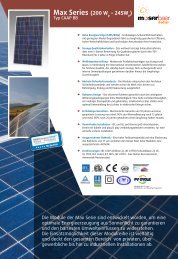
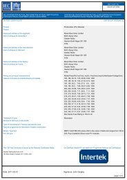
4 MAINTENANCE<strong>Moser</strong> <strong>Baer</strong> Photovoltaic modules require very little maintenance, following isrecommended to ensure optimum performance.1. In view of the tilt angle of the PV modules , normal rainfall is sufficient to keep themodule glass surface clean in most weather conditions. However, if dirt build upbecomes asexcessive, clean the glass surface only with a soft cloth or spongeusing water.2. A mild non abrasive cleaning agent can be used for stubborn dirt. Do not use highpressure water spray or chemicals to clean the module.3. In order to ensure proper operation, please check all wiring connections,condition of the insulation and mechanical connections every six months.4. Observe the maintenance instructions of all components used in the systemssuch as support frames, inverters, battery and charge controller etc5 MODULE SPECIFICATIONSMBSL MAX SERIES SOLAR PV MODULESS.NoTypical Electrical ParametersUnitMBPV CAAP BB1Nominal Power at STC, Pmax[W]18018519019520020521021522022523023524023456Power tolerance at STC (min / max)Voltage at Pmax , VmpCurrent at Pmax, ImpOpen circuit voltage, VocShort Circuit Current, Isc%[V][A][V][A]26.956.6836.107.5527.536.7236.157.6227.906.8036.207.6528.476.8536.207.6828.816.9735.997.65±328.907.1135.927.7129.127.2136.027.8529.217.3636.217.9329.427.4736.468.0029.807.5536.858.0930.127.6237.118.1830.597.6837.348.2430.807.8037.698.347NOCT°C45±28Maximum System Voltage(IEC/UL)V DC1000/6009Temperature Coefficient of Pmax%/K-0.45 ± 0.0510Temperature Coefficient of Voc%/K-0.35 ± 0.0511Temperature Coefficient of Isc%/K0.115 ± 0.00512IP Protection LevelIP 6513Maximum Series Fuse Rating[A]1514Operating Temperature°C-40 to +85Mechanical Parameters1Cell TypeMulti Crystalline Cells2Cell Sizemm156 x 1563No. of Cellsnos60 ( 10 X 6 Matrix )4Module Overall Dimensions (AXBXC)mm1661 x 991 x 375Weight (Approx.)kg18.76Maximum Wind Resistancem/s607 Maximum Hail Diameter @80Km/hmm25Note : STC : Irradiance 1000 W/m², Module Temperature at 25°C and AM 1.5 spectrum14
4.0" Electrical characteristics are within+/-10 percent of measured values of Isc,Vocand Pmax under at Standard Test Conditions of: 1000 W/m2, 25°C celltemperature and AM 1.5 spectrum."" Under normal conditions, a photovoltaic module may produce current and/orvoltage that are different than those listed in the datasheet.at Standard TestConditions. Accordingly, during system design the values of ISC and VOC markedon UL Listed modules should be multiplied by a factor of 1.25 when determiningcomponent voltage ratings, conductor ampacity, fuse sizes and size of controlsconnected to the module output." Refer to Section 690-8 of the National Electric Code for an additional multiplyingfactor of 125% (80% derating)which may be applicable.15
6 PRODUCT IDENTIFICATION1. Each module has a name plate/label on its rear side detailing product type, ratedpower,rated voltage, open circuit voltage, short circuit current all as measuredunder Standard test condition (STC), weight , maximum fuse rating etc.2. Each individual module has a unique identification vide a 15 digit alpha numericcode which is bar coded and the label is permanently affixed on the interior of themodule before lamination, visible on the front side of the module.3. The code is typically "MB XX X XXX XX XX XXX". The date of manufacture of theproduct can be deciphered from the 6th , 7th and 8th digit - day of the year and the9th and 10th digit - the year code.7 DISCLAIMER OF LIABILITYThe information in this manual is based on <strong>Moser</strong> <strong>Baer</strong>'s knowledge and experienceand is believed to be reliable, but does not constitute a warranty expressed or implied. <strong>Moser</strong> <strong>Baer</strong> <strong>Solar</strong> <strong>Limited</strong> does not assume responsibility & expressly disclaimsliability for loss, damage, or expense arising out of, or in any way connected withinstallation, operation, use, or maintenance of PV modules as per this manual. Noresponsibility is assumed by <strong>Moser</strong> <strong>Baer</strong> <strong>Solar</strong> <strong>Limited</strong> for any infringement of patentsor other rights of third parties that may result from use of PV modules. No license isgranted by implication or under any patent or patent rights.<strong>Moser</strong> <strong>Baer</strong> <strong>Solar</strong> <strong>Limited</strong> reserves the right to change the manual , the specificationsor product information sheets without prior notice.16
Manufactured by:<strong>Moser</strong> <strong>Baer</strong> <strong>Solar</strong> <strong>Limited</strong>, IndiaRe-energizing the World!Doc. No. PV/CN/ENG/WI/016 / Rev no. 01, Rev. Date: 30/11/2010