ADD-180G-xx Integral ACTUATOR - Huegli Tech
ADD-180G-xx Integral ACTUATOR - Huegli Tech
ADD-180G-xx Integral ACTUATOR - Huegli Tech

Create successful ePaper yourself
Turn your PDF publications into a flip-book with our unique Google optimized e-Paper software.
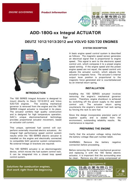
Product Information<strong>ADD</strong>-<strong>180G</strong>-<strong>xx</strong> <strong>Integral</strong> <strong>ACTUATOR</strong>forDEUTZ 1012/1013/2012 and VOLVO 520/720 ENGINESSYSTEM DESCRIPTIONA basic engine speed control system is describedas follows: The magnetic speed sensor generatesan electrical signal that is proportional to enginespeed. This signal is sent to the electronic speedcontrol unit, which compares it to a preset enginespeed setting. If the engine speed and the presetengine speed are not equal, the speed control unitadjusts the actuator current, which adjusts theactuator’s magnetic force. The actuator’s internaloutput lever position is proportional to themagnetic force generated and is counterbalancedby an internal return spring.INTRODUCTIONThe 180 SERIES <strong>Integral</strong> Actuator is designed tomount directly to Deutz 1013/2012 and Volvo520/720 engines. The existing mechanicalgovernor is removed from the engine and the 180SERIES integral actuator is mounted in its place.The actuator exhibits high quality constructionand is designed for high temperature operation.GAC’s unique electromechanical technologyprovides proportional actuator movement, basedon actuator coil current.This unique, optimized fuel control will outperformexternally mounted electric actuators. Anintegral high performance speed control systemresults when the 180 SERIES electric actuator isinstalled on the engine and electrically connectedto compatible GAC governor system components.No external linkage or brackets are required.The 180 SERIES actuator is an electromagneticdevice, which moves the fuel system control rack.It can be integrated into a closed loop speedcontrol system.INSTALLATIONInstalling the 180 SERIES actuator involvesremoving the engine’s mechanical governorcontrol. Therefore, engine shutdown is achievedby switching off the power supply to the speedcontrol unit. The actuator return springcounteracts the engine’s internal fuel rack springby forcing the rack to zero fuel.Since the design incorporates precision parts ofsuperior quality and is sealed from theenvironment, outstanding reliability results. Nomaintenance is required.PREPARING THE ENGINEVerify that the actuator voltage rating matchesthe battery voltage (See part number label).WARNING: Remove the battery negativeconnection before proceeding.Before removing the engine’s mechanical governorand replacing it with the 180 Series electricactuator, it is important that the surrounding areabe clean. Remove any dirt using compressed air2055 V2.1 06.11.2007 Page 1 of 3
Product Informationor a suitable cleaning solvent. Prevent anycontamination from entering the engine. If asolvent is used, place a suitable containerunderneath the mechanical governor to collect thewaste solvent and dirt. Dispose of the wastesolvent by an environmentally accepted method.Unbolt the engine’s mechanical governor. Enginelubrication fluid will be present inside themechanical governor.INSTALLING THE <strong>ACTUATOR</strong>Required material:- Installation Instructions for 180-Series actuator- Loctite 638 (frost plug), 242 (screws)- Liquid silicone gasket- KT-180-HT Installation kit, containing:- 1 Frost Plug No. 0118-1410- 4 Screws M8x551. Install the frost plug to seal off the area thatallowed flow of lubrication fluid to the mechanicalgovernor.The 180 SERIES electric actuator does not requirelubrication from the engine. Installing this frostplug will insure that sufficient lube oil pressure willbe maintained in the engine.2. Adjust the max fuel stop in the actuator.For frost plug mounting and max fuel adjustmentplease refer to the installation instructions.3. Use a small amount of silicone gasket maker toseal the mounting surface of the 180 SERIESelectric actuator. A bead of the silicone gasketmaker material should be placed in both circulargrooves that are located on the actuator’smounting surface on the engine.WIRINGThe 180 SERIES has a dedicated 12 or 24-voltcoil. The actuator models are identified in Chart1. Insure that the actuator voltage matches thebattery supply voltage.An actuator cable harness is used to connect the180 SERIES actuator to the selected GAC speedcontrol unit. No polarity needs to be observed.The cable harness with mating half connectorprovides a vibration resistant and environmentallysealed electrical connection. See the specificspeed control unit literature for additional wiringinformation.TROUBLESHOOTINGIf the electric governor system fails to operate,and the actuator is suspected to be the problem,make the following tests.Measure Coil Resistance (Room Temp.)2.4 ohms 12 VDC9.8 ohms 24 VDCMeasure Coil Isolation (Each wire to actuatorhousing)>1M ohmRemove the small actuator cover. Manually movethe actuator lever through its range of motion. Nobinding or sticking should occur. Energize theactuator to full fuel (follow the steps in the speedcontrol unit publication). The actuator shouldoperate smoothly throughout its entire strokewithout any binding or interruptions in motion.If the actuator passes these tests, the problem islikely elsewhere in the governor or fuel system.Refer to the speed control unit publication foradditional troubleshooting information.ActuatorModel12 Volt 24 Volt w/ Mating Connector<strong>ADD</strong>-<strong>180G</strong>-12 X X<strong>ADD</strong>-<strong>180G</strong>-24 X XSPECIFICATIONSOperating Voltage 12 or 24V DC availableTypical Operating Current 3.5 Amps @ 12V DC2.0 Amps @ 24V DCMaximum Current (cont.) 5.5 Amps @ 12V DC3.0 Amps @ 24V DCOperating TemperatureRange -40°to 100°CRelative Humidity up to 100%All Surface FinishesFungus proof& Corrosion resistantDimensionsSee illustrationWeightMountingTestingMating Hardware3.1 kgdirectly on engineDeutz 1013/2012& Volvo 520/720All Units 100% TestedConnectorEC-1300 included2055 V2.1 06.11.2007 Page 2 of 3
Product InformationDIMENSIONS2055 V2.1 06.11.2007 Page 3 of 3