Cryogenic storage of Ammonia.pmd - Uhde India Limited
Cryogenic storage of Ammonia.pmd - Uhde India Limited
Cryogenic storage of Ammonia.pmd - Uhde India Limited

You also want an ePaper? Increase the reach of your titles
YUMPU automatically turns print PDFs into web optimized ePapers that Google loves.
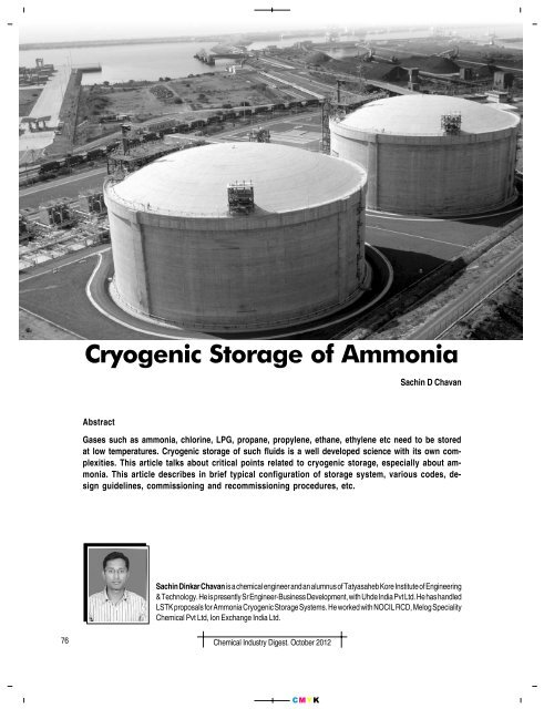
<strong>Cryogenic</strong> is a Greek word meaning “the production<strong>of</strong> freezing cold,” however, the term is usedtoday as a synonym for the low temperature state.It is not well defined at what point on the temperaturescale refrigeration ends and cryogenic begins.There are number <strong>of</strong> gases that require cryogenic <strong>storage</strong>se.g. ammonia, chlorine, LPG, propane, propylene,ethane, ethylene, natural gas, oxygen, nitrogen, hydrogenetc.In this article we have described about the differenttypes <strong>of</strong> ammonia <strong>storage</strong>s methods, typical configuration<strong>of</strong> <strong>storage</strong> systems, various codes and standards, designguidelines, guarantees involved, commissioning &recommissioning procedures, hazardous area classification,safety aspects, ammonia transportation challengesand opportunities for cryogenic <strong>storage</strong>s.Types <strong>of</strong> ammonia <strong>storage</strong> tanksLiquid ammonia is usually stored either at ambienttemperature under high pressure or at -33 o C under atmosphericpressure. In some cases, it is also stored at intermediatetemperatures and pressures (semi-refrigerated).❖❖❖Pressurised <strong>storage</strong> (pressure: 12 – 18 kg/cm 2 g) atambient temperature for small capacities (up to 100MT) is in horizontal pressure vessels.Semi-refrigerated <strong>storage</strong>is in spheres for capacitiesup to 2000 MT(pressure 4 – 6 kg/cm 2g).Atmospheric pressure<strong>storage</strong> is at -33 o C forlarge capacities (2000MT and higher). Thereare three differenttypes <strong>of</strong> tanks for suchCarbonsteelcontainerInsulation<strong>Cryogenic</strong> Storage<strong>Ammonia</strong>dischargelineConcretefoundationFig A1. Single wall with external insulationcryogenic <strong>storage</strong>, viz:A) Single Wall TankB) Double Wall TankC) Double Integrity Cup-In TankLet us review each one separately.A) Single wall tankThese are the tanks with one steel bottom and walldesigned to contain the full liquid level <strong>of</strong> ammonia. Insulationis provided on the external surface to minimizeheat leakage Fig A1. External containment is provided inthe form <strong>of</strong> dyke wall to contain the liquid coming outdue to rupture <strong>of</strong> inner tank. From Health, Safety and Environmentperspective single wall tanks are not recommendedand hence these are no longer built. ExistingSingle wall tanks are being replaced with Double IntegrityCup-In Tanks. See Fig A2.B) Double wall tankThe outer tank is intended to contain refrigerated productleakage from inner tank but is not intended to containany vapor resulting from product leakage from theinner tank which means, it will be released to atmospherethrough flare. See Fig B1 and Fig B2. The outer containeris normally provided in the form <strong>of</strong> “Bund wall” <strong>of</strong> heightCarbonsteelcontainerInsulationFig 1. Single wall tanksConcrete for carbonsteel weatherprotection<strong>Ammonia</strong>discharge lineConcretefoundationFig A2. Single wall with external wallCarbonsteelinner tankInsulationCarbon steelouter tank<strong>Ammonia</strong>discharge lineCarbonsteelinner tankInsulationCarbon steelouter tank<strong>Ammonia</strong>discharge lineConcretefoundationConcretefoundationFig B1. Double wall TankFig B2. Double wall tank with common ro<strong>of</strong>Fig 2. Double wall tanksChemical Industry Digest. October 201277CMYK
<strong>Cryogenic</strong> StorageRo<strong>of</strong>Mineral woolSuspended deckPUF Insulation withaluminium claddingLiquid <strong>Ammonia</strong>CupOuter tankAnnular spacePCCConcrete deckPerlite concreteFig C. <strong>Ammonia</strong> <strong>storage</strong> tank. Double integrity cup-in-tank (typical sketch)Foam GlassSand Layercorresponding to hold equivalent amount <strong>of</strong> liquid in the<strong>storage</strong> tank.C) Double Integrity Cup-In TankThis Double Integrity Cup-In provides extra vaporspace <strong>of</strong> 15 – 20% depending on tank dimensions whichis very useful for maintaining tank pressure within operatinglimits especially under emergency condition. Thepresence <strong>of</strong> ammonia vapor in the annular space betweenthe cup and shell acts as an insulating media and helpsin reducing the heat ingress from outside. See Fig C.The tank is designed as per the API 620, Appendix R.The outer tank is insulated with rigid polyurethane foaminsulation that is formed in-situ. The bottom insulationis foam glass and Perlite Concrete which is a load bearinginsulation. The top <strong>of</strong> the cup is insulated by mineralwool/fiber glass wool insulation which is spread ona suspended deck. Insulation thickness is determined tolimit the tank boil <strong>of</strong>f within 0.04 wt% per day.The tank is equipped with two pressure relief valvesto safeguard against overpressure. Isolation valves areprovided with suitable mechanical interlock. Also thetank is equipped with two vacuum relief valves to safeguardthe tank against vacuum isolation valves are providedwith suitable mechanical interlock.The tank rests on elevated foundation for a free passage<strong>of</strong> air from below, so as to avoid freezing <strong>of</strong> foundation.A staircase tower with platform landing up to tanktop is provided to access tank’s top nozzles.System ConfigurationThe cryogenic ammonia <strong>storage</strong> system comprises <strong>of</strong>the following:❖❖❖❖❖❖❖❖❖❖❖Ship Unloading ArmCross country pipe lineAtmospheric <strong>Ammonia</strong> Storage Tank (Double IntegrityCup-In Tank)<strong>Ammonia</strong> Refrigeration System (Includes Screw compressors,Condensers, Receiver etc.)<strong>Ammonia</strong> transfer pumpsFlare system<strong>Ammonia</strong> drain tank<strong>Ammonia</strong> pre-heater (If applicable)Road/Rail loading/unloading station (If applicable)All Utility equipment (Cooling tower with Side streamfilters, Instrument air compressor system, DG Systemetc.) – Considering stand alone <strong>storage</strong> systemElectrical & Instrumentation systemApplicable Codes and standards<strong>Cryogenic</strong> <strong>storage</strong> tank have to confirm to these codesand standards;❖❖❖❖❖ASME, Sec. VIII, Div. 1 code for pressure vessels (receiverand drain tank) and heat exchangersTEMA Class R code for ammonia heat exchangersAPI 619 for ammonia refrigeration screw compressorsAPI 610, 10 th Edition for ammonia pumpsAPI-RP 520/2000, ASME Sec. VIII, Div. 1 for safetyvalves78Chemical Industry Digest. October 2012CMYK
<strong>Cryogenic</strong> Storage❖❖❖❖❖❖❖ASTM/ASME Sec. II for material specificationAPI 620 Appendix R Feb 2008 edition + Addendum1 2009 + Addendum 2 2010 for <strong>storage</strong> tank and DIN4119 sheet 1 & 2 (1961) for ro<strong>of</strong> structureAPI 520/521 for flareIEC/IS standards for electrical equipmentISA and DIN standards for InstrumentsInsulation as per DIN/ANSIFire protection as per local regulationsDesign GuidelinesDesign guidelines to be followed include:❖❖❖❖❖❖❖Pressure safety/vacuum relief valve should be interlockedin such a way that if one <strong>of</strong> the valve is takenout for maintenance then the other valve should bein line. Also they must be provided with mechanicalinterlock.All the first isolation valves are required to be weldedtype on the tank side. The flange valves always havedanger <strong>of</strong> gasket failure.The vacuum and pressure safety valve shall be flangetype.While cooling the tanks from ambient temperature to-33 0 C the tank will undergo the differential expansiontherefore the stairways and the tank protectionrail shall be independently supported.The nozzle orientation <strong>of</strong> the tank particularly shallbe in such a way that the liquid inlet to the tank andthe vapor outlet from the tank shall be away from theeach other. This will reduce the liquid droplets in thevapor line.The nozzles for the level indicator and the pump suctionshall be away from each other. Pump under runningcondition will cause drop in the liquid level,therefore if the liquid level indicator is away from thepump suction it will have better accuracy in the levelmeasurement.The filing nozzle pipe shall be with perforation andthe filling pipe shall extend up to cup bottom so thatsplashing is avoided during the filling operation.Guarantees involved in cryogenic <strong>storage</strong>System❖❖❖Tank CapacityTank Boil-OffLiquid ammonia receipt from ship/plant❖❖Transfer rate <strong>of</strong> liquid ammonia to user plantElectric powerCommissioning & recommissioning procedureImportant steps to be taken during commissioning andrecommissioning.1. Hydrotest, either up to 70 or 100%, depending on thedesign code.2. Purge with nitrogen until the measured oxygen in thedischarge gas is less than 4%.3. Then purge with ammonia gas until the measured oxygenin the discharge gas is less than 0.5%.4. Cool the tank down to as low a temperature as possible,at a cooling rate lower than 1 o C/hr.5. Measure the temperature in the bulk volume <strong>of</strong> thetank, away from the gas inlet.6. Within one week after commissioning and when conditionsare stable, take samples for water and oxygenanalysis from the ammonia liquid in the tank andanalyse them.Decommissioning procedure1. Empty the tank to the absolute minimum liquid level.2. Evaporate the remaining ammonia in a way that ensuresuniform and slow heating, not exceeding 1 o C/hour.3. Measure the temperature in the bulk volume <strong>of</strong> thetank, away from the gas inlet. Give careful considerationto temperature measurements at the lower levels<strong>of</strong> the tank during decommissioning.4. Purge with warm ammonia gas or nitrogen until allliquid ammonia is removed. The bottom area may needto be cleaned before it is possible to get all the ammoniagas out.Hazardous Area Classification<strong>Ammonia</strong> <strong>storage</strong> tank and associated facility falls underClass 1 and Zone-2.❖ Class 1 – For flammable liquids, gases and vapors❖ Zone 2 – Area in which explosive gas atmosphere isnot likely to occur under normal operations and if itdoes occur it will exist for short period only.Gas Group❖ All gases and vapors are classified in to 4 majorgroups namely, I, IIA, IIB, IIC as per IS 2206. The classificationis based on the minimum ignition energy requiredto raise the temperature <strong>of</strong> gas locally to attainChemical Industry Digest. October 201279CMYK
<strong>Cryogenic</strong> Storageits ignition temperature. <strong>Ammonia</strong> falls under the gasgroup – IIA.Temperature Class❖ <strong>Ammonia</strong> falls under the temperature class – T1<strong>Ammonia</strong> TransportationA) By Ship❖ Sizes <strong>of</strong> ships generally range between 2000 MT to46500 MT.❖ Ships are equipped with refrigeration facilities andpumps. Similar to those <strong>of</strong> <strong>storage</strong> tanks.❖ They are designed for carrying multiple liquids <strong>of</strong> differentdensity and temperature.B) By Rail/Road❖ <strong>Cryogenic</strong> liquid is transported by the rail tankers(BTAL) for short distance. It is unloaded into the <strong>storage</strong>tank via flash vessel or surge drum to control thepressure in the tank.❖ Generally, rail/road tanker loading station has followingfacilities❍ Liquid loading arm❍ Vapor return arm❖ Shut-<strong>of</strong>f valve interlocked with the flow controller onloading line and also with emergency stop switch❖ Flow measurement, recorder and control system for thesafe loading into the tanker❖ Drain Pot (if required)Safety AspectsSafety <strong>of</strong> the cryogenic tanks is <strong>of</strong> prime importance.These tanks are designed for double integrity as againstthe normal tanks <strong>of</strong> API 650 which are designed for singlecontainment. These tanks have inner cup to contain theliquid and also have an additional outer tank to containthe liquid in case <strong>of</strong> cup failure. Utmost care is to be taken❖❖❖❖❖❖❖while designing the inner cup as well as outertank as both inner and outer tanks will be subjectedto various different load combinations.❖ These tanks are subjected to low temperaturesand accordingly are equipped with variouscritical features like special anchorage andits attachment, ability to handle differentialexpansion, special insulation for outer tank/tank bottom/suspended deck etc. In view <strong>of</strong>this, various stringent requirements for materials,fabrication/welding, inspection and testing<strong>of</strong> tank must be considered which are differentand stringent from normal API 650 AtmosphericStorage Tanks.Storage tank design is required to meet high safetystandards and flare system is strongly recommended.The flare system consists <strong>of</strong> an adequately sized pipeline(assessed for critical condition) routed to a distantlocation (as per local applicable rules) and releasedat a height and burnt with a pilot gas (usuallyLPG or NG).To limit the risk <strong>of</strong> over pressure in cryogenic reservoirs,it is essential to maintain a sufficiently low temperature(-33 o C) during <strong>storage</strong> and also while fillingthe tank, even if small quantities are involved relativeto the volumes stored. Protective equipment such asbursting and valves, correctly dimensioned, must alsoplay their role.Safety measures and equipment, such as emergencycontrols must be permanently accessible, even in degradedsituations.The redundancy <strong>of</strong> the equipment reduces the probability<strong>of</strong> major accidents but does not exclude it. Multiplication<strong>of</strong> the various types <strong>of</strong> barrier (alarms,servo-system, emergency operating procedures, failsafe security system) while avoiding common sources<strong>of</strong> failure particularly when the stakes are high or theinstallations are particularly dangerous. These aresome <strong>of</strong> the most effective ways <strong>of</strong> reducing majorrisks, but they do not necessary eradicate them. Bearingin mind the quantities stored in cryogenic reservoirs,the potential sources <strong>of</strong> danger in these installationsare numerous; therefore the measures taken onthe technical, organizational and human fronts to preventaccidents should be proportionate to these.Remote shut-<strong>of</strong>f valves on liquid ammonia main inletand outlet line to/from ammonia <strong>storage</strong> tank shouldbe installed.Refrigeration system should be based on reliable screwcompressors with stand-by options.80Chemical Industry Digest. October 2012CMYK
<strong>Cryogenic</strong> Storage<strong>Cryogenic</strong> Storage❖❖❖❖❖❖Adequate fire water grid and water curtain aroundammonia pumps, compressor house and loading/unloading stations should be provided.Thermal relief valves should be installed on the ammonialines where there is any possibility for blockageor heat ingress.<strong>Ammonia</strong> leak detection system should be providedfor <strong>storage</strong> installation.Lighting protection and earthing protection should beconsidered for <strong>storage</strong> tank.Emergency power is should be provided to one refrigerationholding compressor to maintain tank pressureduring power failure.Wind direction indicator should be provided.Challenges & Opportunities❖ <strong>Ammonia</strong> Stints (That’s good and bad)❖ Storing millions <strong>of</strong> gallons <strong>of</strong> ammonia presents environmental,health & safety concerns❖ <strong>Ammonia</strong> handling is very energy intensive and competitive❖ Energy prices are hitting ammonia manufacturing andhandling very hard❖ Many <strong>of</strong> the facilities were built in the old days andneed to be upgraded to newer technology❖ Due to the very low temperature these liquefied gasescannot be managed using normal equipments andthus require specially made equipments, known ascryogenic equipments. Commonly used cryogenicequipments are tanks, valves, compressors andpumps.The global market size <strong>of</strong> all cryogenic equipment (notlimited to ammonia) is estimated to be $11 billion in 2011.<strong>Cryogenic</strong> tank has the largest market and majority <strong>of</strong>cryogenic equipment market revenue come from thosetanks. After tanks, valves are the second largest revenuecontributor in cryogenic market followed by compressorsand then pumps.CHEMICAL INDUSTRY DIGESTHighlights - November 2012Articles Advanced Materials Mechanical Equipment R&D/ Innovation Multivariable Predictive Control Erection & Commissioning ChallengesPlus Regular Features and much more . . . .For Advertisement & Subscription contact:BLOCKDALE PUBLISHING15, Purshottam, 21 J. P. Rd, Andheri (W),Mumbai - 400058 Tel: 26207402/26259421Fax: 022-26249725Email: chemindigest@gmail.comChemical Industry Digest. October 201281CMYK