Slepian's Electromagnetic Spaceship 1 Problem - Princeton University
Slepian's Electromagnetic Spaceship 1 Problem - Princeton University
Slepian's Electromagnetic Spaceship 1 Problem - Princeton University

You also want an ePaper? Increase the reach of your titles
YUMPU automatically turns print PDFs into web optimized ePapers that Google loves.
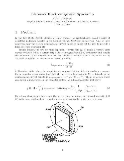
1 <strong>Problem</strong>Slepian’s <strong>Electromagnetic</strong> <strong>Spaceship</strong>Kirk T. McDonaldJoseph Henry Laboratories, <strong>Princeton</strong> <strong>University</strong>, <strong>Princeton</strong>, NJ 08544(June 18, 2006)In the late 1940’s Joseph Slepian, a senior engineer at Westinghouse, posed a series ofdelightful pedagogic puzzles in the popular journal Electrical Engineering. One of theseconcerned how the electric displacement current might or might not be used to provide aform of rocket propulsion [1].Slepian reminds us how the time-dependent electric field E C (t) inside a parallel-platecapacitor that is fed by a current I(t) leads to a magnetic field B(t) both inside and outsidethe capacitor. This magnetic field can be calculated using Ampère’s law, as extend byMaxwell to include the displacement current (density),J displacement = 1 dE C, (1)4π dtin Gaussian units, where for simplicity we suppose that no dielectric media are present.For a capacitor whose plates have area A, the electric field inside is E C =4πQ/A, sothedisplacement current density is J displacement =(1/A)dQ/dt = I/A. Then, for a loop whosearea lies in a plane between the capacitor plates, the induced magnetic field obeys∮B · dl = 4π c∫J displacement · dArea loop = 4π c I ⎧⎪⎨⎪ ⎩1A loopA(A loop >A),(A loop
The displacement current (density) J displacement is “real” in the sense that it leads tomagnetic fields according to the same law (2) as holds for conduction currents. However,Slepian also reminds us that if the displacement current is placed in an external magneticfield, say B 0 , then it does NOT experience a force (density) that is the analog of the force(density) J/c × B 0 on a conduction current (density) J.We now can appreciate Slepian’s suggestion for rocket propulsion based on displacementcurrent. First, consider a coil as shown on the left below, in which the solenoid windingcreates a field B 0 (t) when excited by an AC current I(t). The solenoid winding is split intotwo halves, with a straight segment of wire joining the two halves by crossing the solenoidfield B 0 at a right angle. A length l of this wire experiences a sideways magnetic forceF B = Il × B 0. (3)cThe total force of the circuit on itself is zero, so each half of the solenoid experiences a force−F B /2, which is due to the interaction of the currents in the solenoid windings with themagnetic field due to the current in the wire segment of length l.However, if the wire segment of length l is replaced by a parallel-plate capacitor of gapwidth l, as shown on the right above, there is no force on the displacement current of thecapacitor, while the magnetic field created by that displacement current does exert force−F B /2 on each half of the solenoid winding. Thus, the total force on the circuit with thecapacitor is unbalanced, i.e., −F B , and it appears that the circuit will be propelled to theleft.Note that if the current I is reversed then the magnetic fields are also reversed, but themagnetic forces do NOT change sign, being the cross product of the current and the field. So,the unbalanced force is always to the left, and it appears that Slepian’s AC circuit providesanewformapropulsion.Explain why Slepian’s rocket motor does not work.2
2 SolutionThe solution follows Slepian [2], and expands upon a subtle point.2.1 Slepian’s SolutionNot only does a changing electric field create additional magnetic field, but also a changingmagnetic field induces an additional electric field E ind , as first noted by Faraday. Indeed,Faraday’s law can be put in a form similar to eq. (2) by defining a “magnetic displacmentcurrent”tobeJ magnetic displacement =(1/4π)dB 0 /dt, sothat∮E ind · dl = − 1 ∫dB 0 · dArea loop = − 4π ∫J magnetic displacement · dArea loop . (4)c dtcTaking the loop to be in a plane perpendicular to the field B 0 of the solenoid winding, wesee that the “magnetic displacement current” induces an electric field E ind that circulatesaround B 0 as shown in the figure below. This induced electric field interacts with the chargeson the capacitor plates and exerts a sideways force on them.We adopt a coordinate system in which the x-axis is the axis of the solenoid. Thecapacitor is centered on the origin, with its plates parallel to the x-y plane and its electricfield along the z-axis. Then, for a loop of radius ρ in the y-z plane with its center on thex-axis, and which lies within the region of the uniform magnetic field of the solenoid, we findusing Faraday’s law thatE ind = − ρ dB 02c dt . (5)The component E ind,y of the induced electric field that is parallel to the capacitor plates,3
whose separation is l, isE ind,y = l/2ρ E ind = − l dB 04c dt , (6)independent of position on the plates. The charge Q on each plate is conveniently expressedin terms of the electric field E C =4πQ/A that is perpendicular to the plates. Thus, thesideways electric force on the two plates isF E =2QE ind,y ŷ =2 E CA4π× −l dB 04c dt= − 1 ∫8πcE × dB 0dtdVol, (7)noting that E = E C + E ind ,andthat ∫ E ind × B 0 dVol = 0.It is useful to rewrite the magnetic force (3) in a manner similar to the last form ofeq. (7). Recalling that I = dQ/dt =(A/4π)dE C /dt, wehaveF B = Il × B 0c= Al dE C4πc dtThe total force on the solenoid + capacitor isF = F E − F B = − 1 ∫4πc= − dP fielddtwhereE × dB 0dt dVol − 1 ∫4πc× B 0 = 1 ∫ dE4πc dt × B 0 dVol. (8)dEdt × B 0 dVol = − d ∫dtE × B04πcdVol, (9)∫ E × B0P field = dVol (10)4πcis the electromagnetic field momentum introduced by Abraham [3], building on the Poyntingvector description of energy flow in electromagnetic fields [4].2.2 <strong>Electromagnetic</strong> Field MomentumFor systems in which effects of radiation and of retardation can be ignored, the electromagneticmomentum can be calculated in various equivalent ways [5],∫∫∫ϱA E × B ΦJP EM = dVol = dVol = dVol, (11)c4πcc2 where ϱ is the electric charge density, A is the magnetic vector potential (in the Coulombgauge, where ∇ · A =0),E is the electric field, Φ is the electric (scalar) potential, and J isthe electric current density. The first form is due to Faraday [6] and Maxwell [7], the secondform is due to Poynting [4] and Abraham [3], and the third form was introduced by Furry[8].The vector potential A is related to the induced electric field according to E ind =−dA/dct, so from eq. (5) we have [5],A = − ρB 0φ, (12)24
as expected for a uniform solenoid. The component of the vector potential that is parallelto the capacitor plates isA x = l/2ρ A = − l 4 B 0, (13)independent of position on the plates. The charge Q on each plate is, as before, Q = E C A/4π,so the first form of eq. (11) for the field momentum gives∫ ϱAP EM,1 = dVol = 2QA x ˆx = 1 E C B 0c2 4πc Vol C ˆx. (14)Since ∫ E ind × B 0 dVol = 0, the second form of eq. (11) for the field momentum gives∫∫ E × B EC × B 0P EM,2 = dVol =dVol = E CB 04πc4πc4πc Vol C ˆx. (15)For the third form of eq. (11) we need a representation of the electric potential Φ due tothe charge on the capacitor plates. There will be no net contribution to the field momentumfrom the interaction of the currents in the capacitor plates with the potential, due to thesymmetry of those currents. 1 As a model of the interaction of the current in the solenoidwith the potential of the capacitor, we approximate the capacitor as an electric dipole ofmoment p = Ql ŷ = E C Vol C ŷ/4π. The potential of this dipole at a point at distance r fromthe dipole is Φ = p cos θ/r 2 ,whereθ is the angle between the dipole moment p. For a pointr =(R, φ, z) on the solenoid winding, its rectangular coordinates are (R cos φ, R sin φ, z), sothat r = √ R 2 + z 2 and cos θ = R sin φ/r. The current in the solenoid can be described bythe surface current density vector K = cB 0 φ/4π. Only the x-component of ∫ ΦK dArea isnonzero, and we findP EM,3 =∫ ∫ ΦKx ˆx2πdArea =c 2 0= E CB 0 R 216π 2 c∫ 2πVol C dφ sin 2 φ0∫ ∞Rdφ−∞∫ ∞−∞dz p cos θ K sin φ ˆxc 2 r 2dz(R 2 + z 2 ) ˆx = 1 3/2 2E C B 04πc Vol C ˆx. (16)3 Appendix: Field Momentum of a Spherical CapacitorTo get a sense of whether there exists a significant amount of field momentum in the volumeoutside a capacitor (that resides in a uniform magnetic field B 0 ⊥ E C ), we consider acapacitor whose plates are caps on a sphere of radius a.We use a coordinate system in which E C is along the z-axis, and B 0 = B 0 ˆx is along thex-axis. The electric potential Φ has the form⎧∑ ( n ⎪⎨n A r n a)Pn (cos θ) (ra).r1 We neglect the effect of the variation of electric potential along the wire of the solenoid winding in casethis wire has finite conductivity. We have discussed the field momentum of circuits of finite conductivity in[9].5
in a spherical coordinate system whose polar axis is the z-axis of the capacitor. It is noteasy to determine the Fourier coefficents A n for the general case of spherical caps of angleθ 0 , but it turns out that we will not need these coefficients.We are interested in the y-component of the field momentum,∫ Ez B 0P field,y =4πcThe z-component of the electric field is given bydVol. (18)E z = cosθE r − sin θE θ = −P 1 (cos θ) ∂Φ∂r + sin θ ∂Φ⎧r ∂θ⎪⎨ − ∑ ( )rn A n−1n a=n nP1 P n +sin 2 θP 1 P n′ (r a),noting that dP n (cos θ)/dθ = − sin θdP n (cos θ)/d cos θ = − sin θP ′ n.We first consider the volume integral for the region r>a. In particular, this integralincludes the factor∫ 1−1d cos θ ( (n +1)P 1 P n − sin 2 θP ′ n= 4 3 δ 1n − P n | 1 −1 + x 2 P n | 1 −1 −∫ 1−1) ∫41=3 δ 1n − dx (1 − x 2 )P n′ −1dx 2xP n = 4 3 δ 1n − 4 3 δ 1n =0. (20)Thus, the contribution to the field momentum for r>avanishes at every order n, andsothere is no field momentum stored in the region outside the capacitor.For the region r
[3] M. Abraham, Prinzipien der Dynamik des Elektrons, Ann. Phys. 10, 105 (1903),http://puhep1.princeton.edu/˜mcdonald/examples/EM/abraham ap 10 105 03.pdf[4] J.H. Poynting, On the Transfer of Energy in the <strong>Electromagnetic</strong> Field, Phil. Trans.Roy. Soc. London 175, 343 (1884),http://puhep1.princeton.edu/˜mcdonald/examples/EM/poynting ptrsl 175 343 84.pdf[5] J.D. Jackson, Relation between Interaction terms in <strong>Electromagnetic</strong> Momentum∫ d 3 xE×B/4πc and Maxwell’s eA(x,t)/c, and Interaction terms of the Field LagangianL em = ∫ d 3 x [E 2 − B 2 ]/8π and the Particle Interaction Lagrangian, L int = eφ − ev · A/c(May 8, 2006),http://puhep1.princeton.edu/˜mcdonald/examples/EM/jackson 050806.pdf[6] Part I, sec. IX of M. Faraday, Experimental Researches in Electricity (Dover Publications,New York, 2004; reprint of the 1839 edition).[7] Secs. 22-24 and 57 of J.C. Maxwell, A Dynamical Theory of the <strong>Electromagnetic</strong> Field,Phil. Trans. Roy. Soc. London 155, 459 (1865),http://puhep1.princeton.edu/˜mcdonald/examples/EM/maxwell ptrsl 155 459 65.pdf[8] W.H. Furry, Examples of Momentum Distributions in the <strong>Electromagnetic</strong> Field and inMatter, Am.J.Phys.37, 621 (1969),http://puhep1.princeton.edu/˜mcdonald/examples/EM/furry ajp 37 621 69.pdf[9] K.T. McDonald, Momentun in a DC Circuit (May 26, 2006),7