Technical Information AC fan - SANYO DENKI Global
Technical Information AC fan - SANYO DENKI Global
Technical Information AC fan - SANYO DENKI Global

You also want an ePaper? Increase the reach of your titles
YUMPU automatically turns print PDFs into web optimized ePapers that Google loves.
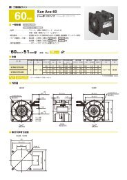
Characteristics calculation method and descriptionReliability and Expected LifeA <strong>fan</strong> generally cools itself as well. The temperature rise of themotor is relatively low and the temperature rise of the grease in thebearings is also low, so expected life is longer than general someeither motors. Since the service life of bearings is a theoretical valuethat applies when they are ideally lubricated, the life of lubricant canbe regarded as expected life of the <strong>fan</strong>. The expected life of an <strong>AC</strong><strong>fan</strong> used at an ambient temperature 60 is 25,000 hours. When themeasurement conditions are: L10 (the remaining product life inthe lifespan test is 90%), with an atmospheric temperature of 60degrees, at the rated voltage and with continuous free air. Theright table indicates the relationship between ambient temperatureand expected life estimated on the basis of our life tests and sameother tests conducted by Sanyo Denki. An accelerated life test isconducted on the basis of the concept that the expected life halvesas the ambient temperature rises by about 15 (within the operatingtemperature range of lubricant.)Expected life of <strong>AC</strong> FansExpected lifeH10 4 10521Expected life25000hL10, 602040 60 80 100 Ambient temperatureRated voltage, continuously run in a free air state, survival rate of 90%<strong>Technical</strong> MaterialNoise characteristicsNoise is average value that measured at 1 meter away from air intake side of <strong>fan</strong>that is suspended on special frame in anechoic chamber (as per JIS B 8330).FanNoise meterAIR FLOWAcoustic radio wave anechoic chamberNoise characteristic measurement equipmentMeasuring air flow and static pressureIt is very difficult to measure air flow and static pressure. Infact, the performance curve may vary greatly according to thetype of measuring equiment.The commonly-used type of measuring equipment is a windtunnel using a Pitot tube. Sanyo Denki uses a very precisemethod using double chamber equipped with many nozzles.U-shaped tubeChamber BThrottle deviceQ 60Av¯AwhereQ = air flowm 3 /minA = cross sectional area of nozzle 4 D2 m 2 D = nozzle diameterv¯ = average air flow velocity of nozzle2g Pn m/sec : Air specific gravitykg/m 3 1.2kg/m 3 at 20 , 1 atmospheric pressureg = acceleration of gravity = 9.8m/sec 2 Pn= differential pressuremm H 2 OPs = static pressuremm H 2 OU-shaped tubeChamber ANozzleAuxiliary blowerFan to be measuredThe measuring equipment using double chanber is method tobe calculated from air flow goes through nozzle and differentialpressure between pressure of inside of chamber (Ps) andatomospheric pressure by measuring differetial pressurebetween air intake and exhaust of nozzle (Pn).Double chamber measuring equipmentConversion TableStatic pressure1mm H 2 O0.0394inch H 2 O1mm H 2 O9.8PaPascal1inch H 2 O25.4mm H 2 O1Pa0.102mm H 2 O1inch H 2 O249PaAir flow1m 3 /min35.31ft 3 /minCFM1CFM0.0283m 3 /min1m 3 /min16.67 /sec1CFM0.472 /sec1 /sec0.06m 3 /min44
<strong>Technical</strong> Material<strong>AC</strong> Fan Common SpecificationsMaterial Frame:Aluminum,Impeller:PlasticsExpected Life Varies for each model(L10:Survival rate:90% at 60 ,rated voltage,and continuously run in a free air state)Motor Construction Shaded coil motor (60mm sq. 80mm sq. 92mm sq. 120mm sq.)Capacitor motor (160mm sq. 172mm)Motor Protection System Burnout protection at locked rotor conditionDielectric Strength 50/60Hz 1500V<strong>AC</strong> 1minute(between input terminal and frame or between lead conductor and frame *For details, refer to the appropriate page.)Insulation Resistance 10M or more at 500VDC megger (between lead conductor and frame)Sound Pressure Level(SPL) Expressed as the value at 1m from air inlet sideOperating Voltage Range 10%Storage Temperature -30 to +70 (Non-condensing)Lead Wire For details, refer to the appropriate page.Overheating protection functionProtection FunctionsIf the <strong>fan</strong> blades are restricted, an overcurrent occurs and leads to a rise in the <strong>fan</strong> coil temperature. This can result in reduced performance,damage, or a fire. To prevent this from occurring, Sanyo Denkis <strong>fan</strong>s incorporate an overheating protection function.Burnout protection function at locked rotor conditionImpedance protection (60mm sq. 80mm sq. 92mm sq. 120mm sq.)This system is used for shading coil-type <strong>fan</strong>s. When the blades are restricted, the current is reduced by the impedance of the coil itselfto prevent a temperature rise in the coil. However, if the applied voltage exceeds the specification range, an overcurrent can occur andresult in overheating, and so care needs to be taken.Thermal protection (160mm sq. 172mm)This system is used for condenser phase-type <strong>fan</strong>s. A temperature sensor is incorporated in the coil so that if the temperature exceedsthe specification temperature, the current is cut off to prevent overheating of the coil.Specifications for <strong>AC</strong> <strong>fan</strong> sensorSpecifications of sensor circuit5VITEM-20*12VITEM-30*Example of model.no109S405ULSystemSpeed detection, Auto-restart, Open collectorPower supply DC5V10%At 5V, 6mA DC12V20%At 12V, 10mARecommend sensor circuit output At Vp5V, I100mA max. At Vp12V, I200mA max.Trip pointStandard speed1,700min -1 10%Low speed 850min -1 10%Response speedStandard speedStartup delay18secDetection delay1secLow speed Startup delay36secDetection delay2secInsulation resistance10 M MIN. at a 500V DC megger(Note)Dielectric strength50/60 Hz, 1,000V <strong>AC</strong>, 1 minute(Note)Ambient conditions Temperature: 10 to 60 , humidity: 90%RH MAX. (at 40 )Sensor schemeExample 1: When the <strong>AC</strong> power for the <strong>fan</strong> and the DC power forthe sensor are turned on at the same time<strong>AC</strong> powerfor <strong>fan</strong>*[ITEM-20] and [ITEM-30] are printed on the<strong>fan</strong> nameplate.Note: Between one end that all sensor leads consistingof brown, yellow and black are tied together andthe G terminal or power terminal of the <strong>fan</strong>.Example 2: When the <strong>AC</strong> power for the <strong>fan</strong> is turned on first,then the DC power for sensor is powered on<strong>AC</strong> powerfor <strong>fan</strong> motorSpeedTrip pointNameplateDC Powerfor sensor circuitSpeedfor <strong>fan</strong>Sensor outputVoltage betweenyellow and black leadsSensor Output Circuit45Sensor circuitTrip pointStartup delay Detection delay Detection delay5VITEM-20*Circuit voltageBrown4.5V to 5.5VYellow100mA MAX.27.6V MAX.Pull-up resistorSensor outputBlackGND0V12VITEM-30*Sensor circuitDC Powerfor sensor circuitSensor outputExample 3: When the DC power for sensor is first powered on, then the<strong>AC</strong> power for the <strong>fan</strong> is turned on<strong>AC</strong> powerfor <strong>fan</strong> motorDC Powerfor sensor circuitSensor outputBrown9.6V to 14.4VYellow200mA MAX.27.6V MAX.Pull-up resistorSensor outputBlackGND0VStartup delayFan speedDetection delayTrip pointDetection delayGND (Black) should be shared in case that power supplyfor sensor circuit (Brown) and that for sensor pull-up(Yellow) are separated.
UPS, inverter, rectifier, high-voltage power supply, etc.Cautions for use of a cooling <strong>fan</strong> in the vicinity of a power switching circuit (prevention of electrolytic corrosion)If a <strong>fan</strong> is installed near a large-power or high-voltage switching circuit, the heavy electromagnetic noise resulting from electromagnetic induction in suchcircuits or the influence of high-frequency noise imposed through the power line of the <strong>fan</strong> may induce current through the shaft bearing of the <strong>fan</strong>.Suchcurrent may damage the oil film on the bearing and even the friction surface of the bearing.This adverse effect is known as "electrolytic corrosion of the<strong>fan</strong>."Electrolytic corrosion affects the smooth revolution of the <strong>fan</strong> and may reduce its service life. An audible symptom is unusual noise emitted from the<strong>fan</strong>.This adverse effect is often observed and may partly be explained by the practice of mounting high-density parts, which reduces the gap betweenthe switching circuits and the <strong>fan</strong> and the use of higher switching frequencies apt to provoke induction. Data processing/communications devices thatoperate at low voltages are not liable to electrolytic corrosion since they generate less electromagnetic noise.A Case of Electrolytic CorrosionFans without anti-corrosion features installed near components thatgenerate electromagnetic noise, such as inverter controllers, areliable to experience electrolytic corrosion.Custom ProductRefer to page 37The curve shown in the graph below represents the relationshipbetween the level of the electromagnetic noise induced by a <strong>fan</strong>and the distance from the <strong>fan</strong> to the noise source.<strong>Technical</strong> MaterialNo. Use Period until the occurrence of unusual noise1 Switching power supply 6 months to 2 years2 UPS 6 months to 2 years3 General-purpose inverter 1 to 1.5 yearsLevel of noise induced by a <strong>fan</strong>Range in which electrolyticcorrosion is generatedRange in which electrolyticcorrosion is not generatedOccurrence of electrolytic corrosion Pattern 1(1)The <strong>fan</strong> gets charged with high-frequency electricity by high-frequency noise (electricfi eld/magnetic fi eld) generated in the switching circuit.(2)Because of high-frequency electricity charged in the <strong>fan</strong>, an electric current fl ows through the bearing of the <strong>fan</strong>.(3)The electric current breaks the oil membrane on the surface of the bearing and the bearing gets abraded (electrolytically corroded).(4)This symptom often occurs in equipment in which switching circuits are sped up and implemented in high density.(5)Countermeasure 1: To provide a shield plate (Note 1) inside the <strong>fan</strong> (The plate should be such that does not interfere with air flow.)(6)Countermeasure 2: To use a <strong>fan</strong> with ceramic bearings.Occurrence of electrolytic corrosion Pattern 2(1)High-frequency electricity fl ows from the circuit board into the inside of the <strong>fan</strong> superimposed with the power line for the <strong>fan</strong>.(2)High-frequency electricity that has entered into the <strong>fan</strong> fl ows through the bearing.(3)Oil membrane on the surface of the bearing gets broken and the bearing gets abraded (electrolytically corroded).(4)Countermeasure 1: To remove high-frequency component between terminals "a" and "b", "a" and "e"and "b" and "e" of the power supply for the <strong>fan</strong>, or to insert a fi lter (Note 2) into the power line for the <strong>fan</strong>.(5)Countermeasure 2: To use a <strong>fan</strong> with ceramic bearings(6)Cables should be twisted in order to decrease induction to the power line for the <strong>fan</strong>.Measures against Electrolytic Corrosion(1) Relocate <strong>fan</strong>s far from all electromagnetic noise sources.(2) Use anti-corrosion <strong>fan</strong>s equipped with ceramic bearings. Refer to page 37(3) As a power supply, the <strong>fan</strong> is wired from a circuit for which noise isnot superimposed.Operating precautionsOperating precautionsDistance from the noise source to the <strong>fan</strong>Switching circuit board of the equipmentComponent parts ofthe switching circuitTerminal aPower supply for the <strong>fan</strong>Terminal bCircuit board grounding*The EMC guard could be effective against electromagnetic noise caused byradiation, but against heavy electromagnetic noise (electromagnetic induction)and conductive noise from the power supply line for a <strong>fan</strong>, we recommendthe use of an "anti-electrolytic corrosion <strong>fan</strong>" with ceramic bearing.Storage temperatureThere is no performance problem when the system is used at between -30 and +70 . There is a possibility that same problem oflubricant and insulation inside motor might occur by condensing due to rapid surrounding temperature change. Therefore, please take careof non-condensing using desiccant or something during <strong>fan</strong> is in storage.ePattern 1Electric field/magnetic field ofthe high-frequency electricityShielding metalGrounding to the cabinetFan cabinetPropellerPattern 2High-frequency electricity is superimposedonto the power line for the <strong>fan</strong>.Metal cabinet of the equipmentReturn path of the high-frequency electricityWindMountingscrewNote 1Shielding metal plateAs an electromagnetic shield metal, "EMC Guard" is available from our company.http://www.sanyodenki.co.jp/products/sanace/<strong>fan</strong>den.htmlCertain shielding effect can be expected from mounting a general-purpose fi nger guardinside the <strong>fan</strong>.In each case, grounding to the cabinet is required.Note2FilterInsert a common mode fi lter when the high-frequency electricity is superimposedon both lines "a" and "b" in the same phase and, if not, insert a normal mode fi lter.Tightening TorqueThis shows the recommended values for the tightening torque wheninstalling the <strong>fan</strong>s. If the tightening torque is higher than the recommendedvalues, the <strong>fan</strong> can be deformed or damaged. Use care when tightening.Recommended screw torquesFans : 0.44Nm (4.5kgfcm) MAX. (with M3 screws)Fans : 0.78Nm (8kgfcm) MAX. (with M4 screws)(160mm160mm172mm)Handling precautionsThe <strong>fan</strong> motor is equipped with a precision ball bearing. Therefore,please handle the motors carefully in order not to shock the bearings.InstallationThere are no limitations on the installation direction. Fans have symbolson the <strong>fan</strong> indicating the airflow direction and blade rotation direction.When installing, use these symbols to check the airflow direction.Air Flow directionDischarge sideSuction sideBlade rotation directionSymbols indicating the <strong>fan</strong> airflow direction and blade rotation direction46