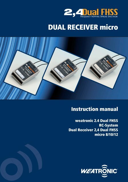
Dual REcEivER Micro
Dual REcEivER Micro
Dual REcEivER Micro
- No tags were found...

You also want an ePaper? Increase the reach of your titles
YUMPU automatically turns print PDFs into web optimized ePapers that Google loves.
1 introductionThe weatronic 2.4 <strong>Dual</strong> FHSS family of products was designed in Germany by a team consisting of communication specialists and informationtechnology specialists. The results are highly sophisticated products based on the latest standards and electronic elements available. Highest qualityand reliability were the goals for these products. During the manufacturing process every units gets tested by a combination of optical and electronictesting procedures. Development, manufacturing of the electronic print boards, housings final assembly are all done in.All components of the weatronic 2.4 <strong>Dual</strong> FHSS RC-Systems are CE-certified and meet all the specs set by the EU (ETSI) as well as specified by the USFederal Communications Commission (FCC). All components were vigorously tested in flight to all thinkable load cases. Operational safety and noiseimmunity were the main goals during the development of this family of products. Please carefully read this instruction manual and the Installationproposals thoroughly so that you can utilize the most out of the safety potential and the multitude of options that the 2.4 <strong>Dual</strong> FHSS RC-Systemsprovide.The Declarations of Conformity for the ETSI and FCC can be found at the website www.weatronic.com or www.weatronic-usa.com.2 Scope of deliveryThe scope of delivery of a 2.4 <strong>Dual</strong> FHSS RC-system including a <strong>Dual</strong> Receiver 2.4 <strong>Dual</strong> FHSS micro consists of:• 2.4 <strong>Dual</strong> FHSS 12 channel transmitter module• Mounting adapter (Disc fitting)• Patch cable• Adapter module for the intended transmitter (some come with a housing)• <strong>Dual</strong> Receiver 2.4 <strong>Dual</strong> FHSS micro 8, 2.4 <strong>Dual</strong> FHSS micro 10 or 2.4 <strong>Dual</strong> FHSS micro 12Optional accessories (not included in the basic package)• micro-SD-card for the 2.4 <strong>Dual</strong> FHSS transmitter module• USB-Mini-cable for connecting the transmitter module to your PC (only needed if programming of the receiver with the Giga Controlprogramming software is desired)• USB-adapter cable for Firmware updates of the <strong>Dual</strong> Receiver 2.4 <strong>Dual</strong> FHSS micro• Electronic ON / OFF switch• Electronic Lipo ON / OFF switch with regulator in two versions3 Safety instructionsThe weatronic 2.4 <strong>Dual</strong> FHSS RC system is designed in particular for the operation of flying models and helicopters and as such is restricted for thisuse only. Children under the age of 14 are only allowed to operate RC models under supervision of an adult. weatronic can not be held liable for anymisuse of the system.3.1 On the airfieldOperate your RC-model only on dedicated RC model fields. Respect other pilots and arrange safety procedures with them. If several pilotsare operating models at the same time, be in close proximity to each other so that you can communicate and coordinate intendedoperations such as take offs and landings to avoid accidents. Fly in the designated areas only. Do not fly over people and bystanders orvisitors.The weatronic 2.4 <strong>Dual</strong> FHSS-System may be operated at the same time with other 2.4 GHz systems as well as with 35/72 MHz systems. There is nofrequency control needed for the operation of the 2.4 systems. Up to 120 weatronic 2.4 <strong>Dual</strong> FHSS-systems may be safely operated at the same timewithout interference.3.2 Range checkAlways perform a range check prior to any first flight of a day. Also see chapter 6.6
<strong>Dual</strong> <strong>REcEivER</strong> micro3.3 Routine checksPrior to every flight do the following routine checks:• First switch on transmitter then receiver.• Check that you have chosen the correct model in your transmitter.• Check that all control surfaces are working and that they are working in the right direction.• Check that all batteries are adequately charged.• Check that you have a micro SD-card inserted into the transmitter module for logging the data for the flight. For more info refer to chapter 5.• Check that all mixer functions are working correctly.• With transmitter and receiver both turned on, both of the green status lights (transmitter module and receiver) have to be on continuously.The transmitter module red light (in the middle) should not be illuminated at all.• For further functions of the lights on the transmitter module, see chapter 9.• Prior to starting the engine of a model, the model has to be restrained by either another person or a staring fixture.Make sure that no other person is within a range of 10 feet of the engine. For Turbine starts make sure that no person or other objectsare within 15 feet behind the exhaust area.Especially with electronic powered aircraft, make sure that the throttle is set to idle / off on the transmitter before turning on the receiver.This will avoid accidental start up of the propeller / rotor.3.4 installation in the modelThe correct installation of the receiver, the batteries, the servos as well as the routing of the cables and antennas are essential for the safe operation ofthe RC-system. weatronic 2.4 <strong>Dual</strong> FHSS <strong>Dual</strong> Receivers have been tested under conditions of extreme vibrations and extreme heat. None the less thesystem has to be protected from vibrations caused by the motor or from heat caused by exhaust systems or sun. Do not install the receiver in directvicinity of the exhaust system. It is best to mount the receiver to a surface with the help of strips of heavy foam and to allow air to circulate aroundit. Do not wrap the receiver into foam or other materials.3.5 antenna installationEach circuit of the <strong>Dual</strong> Receiver 2.4 <strong>Dual</strong> FHSS micro receivers is fed by a shielded antenna of 8 inch length. The effective antenna length though isonly the last 29 mm that are exposed at the end. The ends should be routed as far apart as possible and be angle at 90 degrees to each other.Exception: Carbon fuselages or fuselages with high carbon content. In these cases the antennas should be exposed outside of the fuselage.Carbon fiber has a strong shielding effect and will greatly reduce the range of the system extremely. The same counts for fuselages that havea metallic paint, a metal surface or are covered with a metal foil.4 Radio link descriptionThe weatronic 2.4 <strong>Dual</strong> FHSS RC-system is a proprietary development of the weatronic Company. The transmission of the signals is performed in themicro wave range in the 2.4 GHz-ISM-Band. For users who do not intend to acquire an individual license for every system, rules have been established.These rules have been established by the ETSI (European Telecommunications Standards Institute) and the US FCC. These rules were established tocreate telecommunication standards for all manufacturers and users.For being able to utilize the maximum allowed transmission power of 100mW EIRP, the rules in Europe mandate the use of the so called FHSS.(Frequency Hopping Spread Spectrum) weatronic uses 80 distinct frequencies with a channel width of 1 KHz each. Transmitter and receiver arehopping on these 80 channels at a rate of 100 jumps / second in a pseudo-random sequence. The algorithm (succession order of channels visited) isknown only to the transmitter and the bound receiver. Disturbed channels are being avoided until available again. This is called an.<strong>Dual</strong> FHSS in this context has three characteristics:• The transmitter works with a transceiver module and receives with both antennas• The receiver has two complete receiver units with their own individual antenna.• In addition to the transmission from the transmitter to the receiver- a return signal gets sent back from the receiver to the transmitter. (truelive feedback)The transmitter antennas are so called polar (surface)antennas, as they are being used in GPS systems or cell phones. They have a big advantage.Because of their circular polarization, the characteristic transmission pattern is close to being ideal. They are far superior to the commonly used linearpolarized W-LAN rod antennas.Circular polarized antennas create a more stable link, if obstacles intrude into the path of the link. Obstacles absorb some of the signals dependingon the materials in different polarization planes, so that signals from polarized antennas are less likely to be absorbed and with that provide a saferlink.
The weatronic transmission system is almost totally insensitive to the position of the transmitter towards the receiver, thus also providing the bestreceiving strength of signals by the receivers due to their insensitivity of orientation towards the transmitter.The transmitted data is coded so that only the receiver, which is matched to the same code, is able to decode the signals and transform them intoservo signals. There are several million codes available and each one is only given out once.The transmitter module logs all data of the transmitter as well as the receiver on a micro-SD-Card. Even after a power failure of the transmitter battery,the system keeps recording, to allow later analysis of the problem.All the <strong>Dual</strong> Receiver 2.4 <strong>Dual</strong> FHSS micro’s are designed as transceivers with a reporting return channel. They are capable of returning telemetrydata and other basic info such as receiver strengths, battery voltage and temperature in the receiver back to the transmitter module. Standard withthese receivers is the report of the following data,• Receiver signal strength (for range warning)• Receiver Batterie voltage (voltage warning)• Temperature (temperature warning)That get returned to the transmitter and will give an optical (red LED in the middle) and acoustical (Earphone jack) warning to the operator. With thesoftware GIGAControl one can edit the thresholds of the alarms. The data will be recorded on the SD-card for data logging. Additionally while flying,one can also look at the live stream on the computer while connected to the transmitter module.So far the weatronic transmitter modules have been adapted to transmitters of the following brands: Multiplex, Futaba, and JR / Graupner. At this timea maximum of 12 channels are available, depending on the transmitter type. (an upgrade to 16 channels is in the planning stadium)Modules for the following transmitters / systems are currently available.• Futaba T12 FG/T14 MZ/FX-30/FX-40 (new small frequency module)• Futaba FF 7/FF 9/FF 10/WZ-2/FC-18/FC-28 (older bigger frequency module based on PCM1024)• Multiplex Royal Evo/Royal Pro/Profi MC 3010/3030/4000• Graupner MC 18/MC19/MC 22/MC 22S• Graupner MX 22/MC 24/JR 9X/JR 10X (Standard JR / Graupner module)• Graupner MX 24S, JR 12 XThis list will be added to as we approve and test more units.5 Transmitter module weatronic 2.4 <strong>Dual</strong> FHSS5.1 Transmitter conversionA transmitter conversion kit consists of:• Transmitter module• Fitting for the installation in place of the original antenna• Patch cable with snap in receivers• Adapter modules partially with housings5.1.1 Transmitter module for Multiplex Evo/Royal Evo Pro 7/9/12Remove the original telescoping rod antenna from its place. Remove the back side of the transmitter housing. Connect the cable coming out of theadapter tube to the weatronic transmitter module. Make sure that the cable snaps into the receiving connector.www.weatronic-usa.com
<strong>Dual</strong> <strong>REcEivER</strong> microThe patch cable of the EVO transmitter is routed through the original telescoping rod antenna tubeRoute the patch cable harness through the original antenna tube to the inside of the transmitter and attach it to the transmitter module adapter.Remove the original Multiplex HF-module. Insert the weatronic module at the place of the removed Multiplex HF-module. Double check, that allconnections are solid. Return the back cover of the transmitter. Finally insert the disc receiver into the position of the antenna and slide the transmittermodule onto its disc.5.1.2 Transmitter module for Multiplex Profi 4000/3030/3010Remove the telescopic 35/72 MHz rod antenna and screw on the mounting disc. Remove the base plate of the transmitter and remove the original35/72MHz module from its slot. Remove the see through window from the back plate or drill a hole on the front bottom of the cover, or route thecable through one of the not used switch slots on the top side of the transmitter.weatronic 2.4 <strong>Dual</strong> FHSS transmitter module installed on Multiplex Profi MC 4000Adapter-printboard and patch cable for Multiplex Profi MC 3030/4000- series and EVO Royal/ Royal Pro 7/9/12Insert the weatronic patch cable into the weatronic transmitter module and make sure that the snap locks it into place. Place the transmitter moduleon the mounting disc and route the other end of the cable through the slot in the lid. You can also route the cable through one of the unused switchpositions on the top of the transmitter. Then attach the free end of the patch cable to the adapter board again making sure the snap engages tosecure the cable to the board. Finally put the adapter board into the same spot as the HF-module (see picture) and reattach the lid. The installationis completed and the transmitter is ready for operation.
5.1.3 Transmitter module for Graupner Mc 24Remove the telescope antenna and remove the bottom lid of the transmitter. Replace the original HF-module with the weatronic 2.4 GHz module.Screw the adapter disc into the antenna position. Either remove the clear plastic window from the bottom lid or route the cable through one of thefree switch holes on the top side of the transmitter. Make sure that both ends of the patch cable are secured by the snap hook. Close the lid and youare ready to go.5.1.4 Transmitter module for Graupner MX 22/JR 9X/JR10X/MX24S/JR 12Xweatronic 2.4 <strong>Dual</strong> FHSS transmitter module on Graupner/JR transmitter MX22Remove the telescopic antenna and the original HF-module. Screw in the adapter disc in the position of the old antenna. Insert the weatronic adaptermodule in place of the old HF-module. As a last step, connect the adapter module with the patch cable to the weatronic transmitter module. Makesure that both ends snap in and place the transmitter module on the mounting disc with the LED lights facing up to the operator.Adapter fitting Graupner MX22/JR9X/JR10X, right adapter module for JR/Graupner5.1.5 Transmitter module for Graupner Mc19/Mc22/Mc22SRemove the existing 35 MHz- telescopic antenna and replace with the adapter provided with the weatronic system. Remove the bottom lid ofthe transmitter and disconnect the 4-wire blue colored connector from the original HF-module. Then insert this blue connector into the weatronictransmitter adapter and mount the weatronic adapter module circuit board with double sided tape in the position as shown in the picture below. Eitherremove the clear window in the lid to route the patch cable through, or use one of the unused switch locations on the top side of the receiver.www.weatronic-usa.com
<strong>Dual</strong> <strong>REcEivER</strong> microConversion of weatronics module on Graupner MC19 transmitter5.1.6 Transmitter module for Futaba FF7/FF9/FF10/WZ-2Please see website www.weatronic.com or www. weatronic-usa.com5.1.7 Transmitter module for Futaba Fc-18/Fc-28Remove the antenna and original HF module. Screw in the disc mount into the original antenna position and insert the adapter module on the backside of the receiver. As a last step, connect the adapter module with the patch cable to the weatronic transmitter module. Make sure that both endssnap in and place the transmitter module on the mounting disc with the LED lights facing up to the operator.weatronic tx module on Futaba FC-28 transmitterAdapter module5.1.8 Transmitter module for Futaba T12 FG/T14Please see website www.weatronic.com or www. weatronic-usa.com5.1.9 Transmitter module for Futaba FX-30/FX-40Please see website www.weatronic.com or www. weatronic-usa.comwww.weatronic.com
105.2 Function of the lEDs in the transmitter moduleThe transmitter module contains three LEDs:• one green (at left) marked „STATUS“• One red in the middle marked „ERROR“ and• one yellow (right) marked „TEST“When the transmitter is switched on, all three LEDs light up momentarily as a check.• Left LED (green):LED off -> no connectionIlluminated continuously-> link is OKPulsing quickly -> QuickbindingPulsing slowly -> Binding• Middle LED (red):LED off -> all OKFlashing -> Error, also an alert reporting different conditions as:- No connection to the receiver- Range alert from the receiver has been triggered- Receiver or transmitter module – low voltage alert has been triggered- Temperature in the receiver or transmitter module has been triggeredThese signals will also be given as a sound signal to the ear phone jack of the transmitter module.• Right LED (yellow):LED off -> no range check in progressflashing -> Range check in progress6 Putting into service for the first time6.1 annotationThe <strong>Dual</strong> Receiver 2.4 <strong>Dual</strong> FHSS micro receivers come in three sizes with 8, 10 or 12 channels. They can be used as any other receiver by plugging inthe servos and go flying. All configurations are controlled by the transmitter. First of all the receiver has to be bound to the transmitter module.For the more advanced and interested RC-pilot, these receivers also may be programmed with the use of the weatronicsoftware GIGAControl. There are a multitude of possibilities that you can do with the programming of the receiver and servofunctions. You can relate any channel to any outlet, program curves, do sequencing, slow functions and other features. Formore information, please go to our website www.weatronic.com or www.weatronic-usa.com and download the program andinstructions for free. As an alternative you can also order a CD with the program and instructions.6.2 Properties of the lEDs on the receiversThe <strong>Dual</strong> Receiver 2.4 <strong>Dual</strong> FHSS micro has two LEDs:• a green LED with the label „Binding – on/off“ and• a red LED with the label „Status“When the receiver is switched on, both LEDs light up momentarily as a check.• LED green:LED off -> no connection to transmitterContinuous on -> Link OKQuick flashing -> QuickbindingSlow flashing -> Binding• LED red:flashing -> Failsafe programming activeFurther flashing codes -> future use
<strong>Dual</strong> <strong>REcEivER</strong> micro11<strong>Dual</strong> Receiver 2.4 <strong>Dual</strong> FHSS micro 12 (left), 12 channel transmitter module (right)6.3 Binding of transmitter and <strong>Dual</strong> ReceiverA weatronic transmitter module may be bound to number of receivers. The transmitter module transmits with a coded sequence (several millionpossibilities), that have to be accepted by the receiver. A simultaneous use of several weatronic receivers is not possible. (Transceiver conflict)The weatronic 2.4 <strong>Dual</strong> FHSS receivers have to be bound to a transmitter/ transmitter module before it can be used. During this binding procedure,the receiver stores the transmitter serial no as well as the transmitter is storing the receiver serial no. This binding procedure only needs to be doneonce. After that the receiver will only listen to that one transmitter. The procedure of Binding is easy and is done as follows:The transmitter module has two micro switches that are „BUTTON 1“ and „BUTTON 2“ indicated on the front side of the transmitter module. Forsafety reasons, these buttons are hot only for a limited time. This is indicated when turning on the module by flashing all three LED’s once.• BUTTON 1 activates the range check.• BUTTON 2 is used for binding and quickbinding.Please take care of a distance between transmitter and receiver of at least half a meter. Turn on the transmitter and choose a PPM modulation. Turnoff and on again and immediately after that press the button 2 until the green LED flashes steadily. Then turn on the <strong>Dual</strong> Receiver 2.4 <strong>Dual</strong> FHSSmicro, insert the red jumper on the back side of the receiver into the top position, connecting the yellow and red pins.As soon as the transmitter and receiver are bound to each other, this will be indicated by a solid green LED light, both on the transmitter module andthe receiver. After that, remove the red jumper from the back side of the receiver and store in a safe place.6.4 use of micro SD cardThe use of a micro SD card is not necessary for the function of the weatronic system but very useful. All flight and operation data are stored on thiscard located in the transmitter module. Install the card on the side of the transmitter module with the connectors on the upper side. You may read outthe flight data by means of our GIGAControl software (www.weatronic.com or www.weatronic-usa.com).6.5 QuickbindingThe transmitter module will recognize all receivers that were ever bound to it. When switching from one receiver (RC-model) to a different one, thetransmitter has to be quick-bound to this other receiver. This is achieved easily. After turning on the transmitter and receiver, just press the Button 2for a short time and the status LED (green) will indicate quick-binding by turning on solid.6.6 Servos and power suppliesThe <strong>Dual</strong> Receiver 2.4 <strong>Dual</strong> FHSS micros have several options, depending on the receiver type. The coding of the pins is as follows(viewed from front):• Top: signal• Middle: plus• Bottom: minusThe 8 and 10 channel versions of the micro receivers have additional plug sots for the battery / power. The 12 channel version has to be poweredthrough a V-cable which can be plugged in at any position. There are several option for the power supply:
12• You can power the receiver with either 4 or 5 cell NimH-batteries.• Alternatively you can power the receiver with either the 5A weatronic Switch/Regulator or• The 10A weatronic comfort-Switch/Regulator both for use with 2 cell Lipos6.7 Failsafe programmingThere are two ways of programming the failsafe of the micro receivers. One is through the GIGAControl software and the other is done as follows.The failsafe programming of the <strong>Dual</strong> Receiver 2.4 <strong>Dual</strong> FHSS micros are initiated from the transmitter. Every channel can be programmed individually.The red jumper has to be inserted into the top position (connecting yellow and red) prior to switching on the receiver.Now you can adjust each channel one by one. For adjustment of a single channel you have to initiate a sequence by moving it to its limits first andthen to the position of failsafe. Failsafe will be stored for every channel that has been activated as been described above, when pulling off the redjumper. Any channel that was not activated will be a hold channel, meaning it will hold its position when going into failsafe.All Failsafe values will be stored at the moment of pulling the jumper. Turning on and off of the receiver will not affect the settings of a channel unlessthe channel has been activated by moving its control beyond 50%.6.8 Range checkFirst off the transmitter and receiver have to be bound to each other.• First switch on the transmitter and after that the receiver.• The transmitter needs to be put into range check modus. The transmitter will then be transmitting at a reduced output power of 1mW(instead of 100mW). To activate this modus, depress the Button 1 for at least 5 seconds right after turning on the transmitter.• The yellow LED on the right side (“test”) will be flashing as a signal that you are in range check modus. You have 60 seconds before thetransmitter returns back to normal transmitting modus.• If you exceed these 60 seconds, you will have to turn off the transmitter again and press the Button 1 again.• You should be able to do 80 to 100 paces (steps) with the transmitter pointing to the model and still have a good link. (No red blinking,indicating an interruption of the link)Should you not be able to achieve this, do not attempt to fly. It will be necessary to evaluate all parameters as positionof the receiver and antennas, cable routings, switches, charging state of batteries on board as well as of the transmitter.6.9 country codesThere are two country codes available:• World: Utilizing the Spread Spectrum from 2.4010 – 2.4835 GHz• France: Utilizing a limited Spectrum from 2,4010 – 2,4530 GHzThe default setting is World. For users operating in France, changing to the French regulations is achieved by depressing both buttons 1&2 on thetransmitter module for five seconds. This will be verified by a flashing of all three LEDs.1 flash: World setting2 flashes: FranceTo return to world setting, repeat the 5 second push on both buttons (1&2).7 liability disclaimerThe installation and operating instructions are given as a guide to best practices. weatronic GmbH has no control over the installation, maintenance,the environment the systems are being used in, nor the operation and accessories used together with this system. weatronic GmbH will not beliable for any damage or costs that result from use of these systems. By law, weatronic GmbH may be liable only to the amount of value paid for theweatronic equipment that was directly related in the damaged case.8 Recycling EuropeElectronic equipment, that has been marked with a crossed out trash can are not allowed to be put into regular trash. They have to be disposed off toa certified recycling system. In countries of the EU (European Union) electronic parts are not to be disposed off into the regular waste system. WEEE(Waste of Electrical and Electronic Equipment Guideline 2002/96/EG). You can dispose off the electronic waste at one of the community collectionagencies at no charge. They will take care, to have it professionally recycled.
<strong>Dual</strong> <strong>REcEivER</strong> micro9 appendix technical specifications9.1 Transmitter module 2.4 <strong>Dual</strong> FHSS 12 channelsTransmission: adaptive frequency hopping spread spectrumFrequency range: 2,401 – 2,4835 GHzPower output: 20 dBm (100 mW)Functions (channels): 12Frequencies: 81, France: 52Intervall: 10 msModulation: Quadrature Phaseshift keyingBack channel for telemetry and sensor dataReal time data via earplug, LED or via PC (GIGAControl)Receive sensitivity: -84 dBmTemperature range: -10°C to +60 °CVoltage: 5 - 10 VoltCurrent consumption: 200 mARange: > 3000 mResolution of channels: 4096 stepsData storing: micro SD cardSoftware: GIGAControlFirmware update: micro SD cardAntennas: 2 patch arealsPolarisation: circularDimensions : 95 x 65 x 18 mmWeight: 60 g19.2 <strong>Dual</strong> Receiver 2.4 <strong>Dual</strong> FHSS micro 8/10/12Double receiver circuitTransmission: adaptive frequency hopping spread spectrumFrequency range: 2,401 – 2,4835 GHzPower output: 20 dBm (100 mW)Functions (channels): 12Frequencies: 81, France: 52Intervall: 10 msModulation: Quadrature Phaseshift keyingBack channel for telemetry and sensor dataReceive sensitivity: -100 dBmTemperature range: -10°C to +60 °CFrequency range: 2,401 – 2,4835 GHzPower output: 20 dBm (100 mW)Functions (channels): 12Frequencies: 81, France: 52Interval: 10 msModulation: QPSK*Back channel for telemetry and sensor dataReal time data via earplug, LED or via PC (GIGAControl)Receive sensitivity: -84 dBmCurrent consumption: 130 mAResolution of channels: 4096 stepsFirmware update: USB adapterAntennas: 2 λ/4 wiresPolarisation: linearAntenna length: 200 mmAntenna length in operation: 29 mmDimensions: 55 x 33 x19 mmWeight: 30 g* Quadrature Phaseshift keying
1Your notes
<strong>Dual</strong> <strong>REcEivER</strong> microYour notes1
Double safety has a name!weatronic GmbHSeidenstraße 57D-70174 StuttgartPhone: +49 -711 -253 92 74Fax: +49 -711 -870 30 994E-Mail: info@weatronic.comwww.weatronic.com