Understanding European wiring diagrams - TheSamba.com
Understanding European wiring diagrams - TheSamba.com
Understanding European wiring diagrams - TheSamba.com

You also want an ePaper? Increase the reach of your titles
YUMPU automatically turns print PDFs into web optimized ePapers that Google loves.
<strong>Understanding</strong><br />
<strong>European</strong><br />
DIN Wiring<br />
BY KARL SEYFERT<br />
<strong>European</strong> <strong>wiring</strong> <strong>diagrams</strong> may look<br />
strange and in<strong>com</strong>prehensible. But they’re<br />
not so tough to understand when the<br />
underlying standards are explained.<br />
Over the years, I’ve<br />
heard many explanations<br />
for why some<br />
technicians choose not<br />
to work on <strong>European</strong><br />
vehicles. For some, it’s<br />
based on their desire to work only on<br />
vehicles built within our borders. For<br />
others, the choice may be based on the<br />
belief that <strong>European</strong> cars are just too<br />
“foreign” and their systems too unusual<br />
or exotic to easily understand.<br />
In today’s automotive economy, it has<br />
be<strong>com</strong>e increasingly difficult to hold<br />
onto these attitudes. Many cars sold in<br />
this country by <strong>European</strong> (and Asian)<br />
manufacturers are actually assembled<br />
right here in the U.S. This blurs the<br />
conventional definition of an imported<br />
vehicle. At the same time, many “American”<br />
cars are actually assembled outside<br />
our borders, further confusing the<br />
accepted definition of a domestic car.<br />
Auto manufacturing is truly a global<br />
enterprise, with all of the major manufacturers<br />
conducting business in several<br />
countries simultaneously. Even if we<br />
38 April 2003<br />
ignore the differences of language and<br />
culture, isn’t it still a difficult problem<br />
for a <strong>European</strong> manufacturer to build<br />
vehicles in a different country like the<br />
U.S.? To oversimplify the challenges<br />
involved, how do you get an American<br />
assembly line to crank out parts for a<br />
<strong>European</strong> car? The answer is standards.<br />
Standards have been an integral<br />
part of the automotive world since the<br />
earliest days of the automotive assembly<br />
line. Standardization of parts allowed<br />
automakers to transform their<br />
businesses from a one-at-a-time proposition<br />
to a many-at-a-time operation.<br />
In this country, the Society of Automotive<br />
Engineers (SAE) is responsible<br />
for maintaining order by establishing<br />
many of the standards that apply to automobile<br />
manufacturing. When you<br />
pick a bolt for a domestic vehicle out of<br />
the bolt bin, chances are the standards<br />
and specifications concerning its<br />
thread pitch and hardness were originally<br />
defined by SAE. Thanks to standardization,<br />
that bolt should thread into<br />
any nut made anywhere in the<br />
Fig. 1<br />
world, as long as it conforms to the<br />
same set of standards.<br />
In Europe, the most widely recognized<br />
organization responsible for establishing<br />
and publishing automotive<br />
standards is called Deutsches Institut<br />
für Normung e.V. Standards established<br />
by this organization are often referred<br />
to as DIN standards.<br />
DIN standards have been established<br />
for a multitude of things, including<br />
many outside the automotive<br />
world, but we’ll limit the focus of this
Fig. 2<br />
article to the DIN standards for automotive<br />
<strong>wiring</strong>. Why <strong>wiring</strong>? Because<br />
that’s the one thing I’ve heard the most<br />
techs <strong>com</strong>plain about when it <strong>com</strong>es to<br />
working on <strong>European</strong> vehicles. For<br />
some, it’s the layout of the electrical<br />
<strong>com</strong>ponents throughout the vehicle.<br />
For others, it’s understanding the<br />
<strong>wiring</strong> <strong>diagrams</strong> that map out the position<br />
and operation of all those systems<br />
and <strong>com</strong>ponents. The <strong>diagrams</strong> may<br />
look strange and in<strong>com</strong>prehensible.<br />
But when you understand the underlying<br />
system and standards that were<br />
used to design the vehicles and the <strong>diagrams</strong>,<br />
it’s not as tough as it first seems.<br />
Terminal Designations<br />
DIN standard 72 552 establishes the<br />
terminal numbering system that’s used<br />
for any <strong>wiring</strong> diagram or vehicle<br />
<strong>wiring</strong> that conforms to DIN specifications.<br />
The terminal codes are not wire<br />
designations, as devices with differing<br />
terminal codes can be connected to<br />
the opposite ends of a single wire. The<br />
chart on pages 42 and 43 outlines<br />
WIRE COLORS<br />
English DIN (German)<br />
Black . . . . . . . . . . . . . . . . . . . . .Sw<br />
Blue . . . . . . . . . . . . . . . . . . . . . .Bl<br />
Brown . . . . . . . . . . . . . . . . . . . .Br<br />
Green . . . . . . . . . . . . . . . . . . . . .Gn<br />
Gray . . . . . . . . . . . . . . . . . . . . . .Gr<br />
Orange . . . . . . . . . . . . . . . . . . .Or<br />
Pink . . . . . . . . . . . . . . . . . . . . . .Rs<br />
Purple . . . . . . . . . . . . . . . . . . . .Vi<br />
Red . . . . . . . . . . . . . . . . . . . . . . .Rt<br />
Turquoise . . . . . . . . . . . . . . . . . .Tk<br />
White . . . . . . . . . . . . . . . . . . . . .Ws<br />
Yellow . . . . . . . . . . . . . . . . . . . .Ge<br />
many of the <strong>com</strong>mon terminal designations<br />
described under DIN 72 552.<br />
Some of the more obscure numbers,<br />
which refer to <strong>com</strong>ponents on trailers,<br />
heavy-duty trucks and such, have been<br />
intentionally omitted.<br />
When you’ve worked with DIN<br />
<strong>wiring</strong> for a while, you’ll begin to recognize<br />
certain numbers that <strong>com</strong>e into<br />
play more often than others. For example,<br />
a terminal 31 designation always<br />
refers to a direct connection to vehicle<br />
ground and a terminal 30 designation<br />
Fig. 3<br />
always represents a direct connection to<br />
the battery positive terminal. And terminal<br />
50 is always battery positive with<br />
the key ON or in the CRANK position.<br />
Wire Color Codes<br />
Before we get into some actual DIN<br />
<strong>wiring</strong> <strong>diagrams</strong>, a word about wire<br />
color codes. Most <strong>wiring</strong> <strong>diagrams</strong><br />
you’re likely to <strong>com</strong>e across will have<br />
already been translated into English.<br />
Wire colors in those <strong>diagrams</strong> should<br />
be labeled with abbreviations you’ll be<br />
able to understand. But just in case<br />
you run across a diagram with the original<br />
<strong>wiring</strong> color codes, use the “Wire<br />
Colors” key at left to sort things out. By<br />
the way, color codes for electrical<br />
<strong>wiring</strong> are defined in DIN 47 002.<br />
Circuit, Block &<br />
Schematic Diagrams<br />
Description of an electrical system or<br />
circuit may begin with a circuit diagram.<br />
This is an idealized representation,<br />
rendered in the form of symbols<br />
to provide a quick overview of circuit<br />
April 2003<br />
39
<strong>Understanding</strong> <strong>European</strong> DIN Wiring<br />
and device functions. The circuit diagram<br />
illustrates the functional interrelationships<br />
and physical links that connect<br />
various devices. These <strong>diagrams</strong><br />
may also include illustrations and simplified<br />
design drawings, as needed.<br />
A block diagram is another simplified<br />
representation of a circuit, showing<br />
only the most significant elements. It’s<br />
designed to furnish a broad overview of<br />
the function, structure, layout and operation<br />
of an electrical system. This format<br />
also serves as the initial reference<br />
for understanding more detailed<br />
schematic <strong>diagrams</strong>. Squares, rectangles,<br />
circles and symbols illustrate the<br />
<strong>com</strong>ponents. Information about wire<br />
colors, terminal numbers, connectors,<br />
etc., are omitted to keep the diagram as<br />
simple as possible.<br />
The schematic diagram shows a circuit<br />
and its elements in detail. By<br />
clearly depicting individual current<br />
paths, it also indicates how the electrical<br />
circuit operates. Most DIN<br />
schematic <strong>diagrams</strong> are current flow<br />
<strong>diagrams</strong>. They’re arranged from top<br />
to bottom, so we can clearly see how<br />
the current flows through the circuit.<br />
In a current flow diagram, a large<br />
block or several lines running across<br />
the top represent the fuse/relay panel.<br />
This is the positive side of the circuit.<br />
The numbered line across the bottom<br />
represents the chassis ground, <strong>com</strong>-<br />
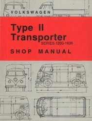
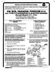
The main fuse and relay panels on most <strong>European</strong> cars<br />
can be found under the hood. On older vehicles, like this<br />
BMW, the panel is protected only by a plastic cover. The<br />
panels on more recent models do a better job of protecting<br />
fuses and relays from the elements.<br />
40 April 2003<br />
Most DIN relays include a miniature<br />
schematic diagram, right on the relay<br />
housing. Flip the relay over and you’ll<br />
find the relay terminals are also<br />
numbered. The numbers correspond<br />
to the DIN terminal designations.<br />
pleting the circuit to the battery.<br />
Occasionally, a wire in a circuit will<br />
be continued in another current track.<br />
When this happens, a small box with a<br />
number inside will send you to the current<br />
track where the wire is continued.<br />
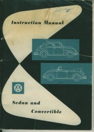
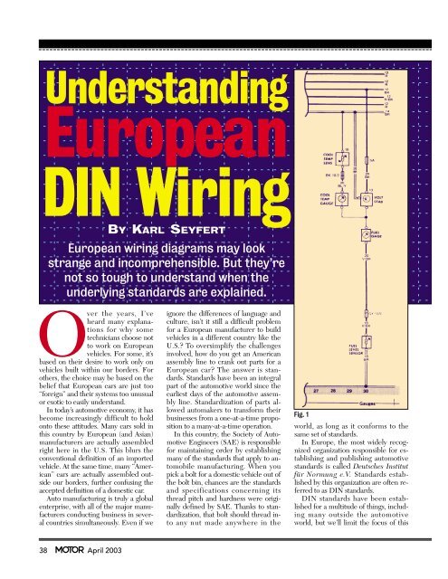
Fig. 1 on page 38 is a schematic diagram<br />
of the gauge circuits on a Volkswagen.<br />
The lines across the top represent<br />
the positive feeds to the circuit. The<br />
numbers next to the bars define their<br />
wire gauge size and color. The individual<br />
gauges are mapped out in sequential<br />
order below, making it very easy<br />
Photos: Karl Seyfert<br />
to see how the current flows through<br />
the various sections of the circuit.<br />
The diagram also includes information<br />
on terminal numbers, wire sizes<br />
and colors, connector sizes and a basic<br />
representation of the internal working<br />
of the gauges and sensors. The symbols<br />
used to define the <strong>com</strong>ponents also<br />
conform to DIN specifications. A key<br />
explaining these symbols will often be<br />
included with the schematic diagram.<br />
Even if you’re fairly familiar with a<br />
circuit on a given car, a schematic diagram<br />
will help you find the correct location<br />
of a ground terminal, or help<br />
you identify a specific pin number in a<br />
connector.<br />
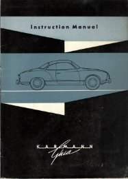
Another example of a current flow<br />
schematic diagram is shown in Fig. 2<br />
(page 39). This diagram also explains<br />
the meanings of some of the letters and<br />
numbers in the diagram. The way the<br />
<strong>com</strong>ponents and wires are situated in<br />
relation to one another in the diagram<br />
usually bears no resemblance to how<br />
they’re actually arranged on the vehicle.<br />
Break this diagram down and you<br />
can see how it can work for you. Four<br />
things are needed to have a <strong>com</strong>plete<br />
circuit: a source of power, wires or conductors<br />
of electricity, a load or a device<br />
that uses electricity and a ground. The<br />
load needs both voltage and ground.<br />
The schematic tells you where they<br />
<strong>com</strong>e from, and where they need to go<br />
Many older <strong>European</strong> vehicles are equipped with these bullet-style<br />
fuses. The exposed fuse is wrapped around the<br />
ends of the plastic or ceramic fuse body. The fuse is held in<br />
place and makes electrical contact via the spring-loaded<br />
terminals at its ends. This fuse type can be the source of intermittent<br />
electrical problems, especially in damp climates.
<strong>Understanding</strong> <strong>European</strong> DIN Wiring<br />
1 . . . . . . . . . . .Ignition Coil, Distributor<br />
Low-Tension Circuit<br />
Ignition Distributor With Two Insulated Circuits<br />
1a . . . . . . . . . .to Ignition Point Set I<br />
1b . . . . . . . . . .to Ignition Point Set II<br />
Ignition Coil, Distributor<br />
4 . . . . . . . . . . . High-Tension Circuit<br />
Ignition Distributor With Two Insulated Circuits<br />
4a . . . . . . . . . .Terminal 4, from Coil I<br />
4b . . . . . . . . . .Terminal 4, from Coil II<br />
15 . . . . . . . . . .Switch-Controlled Positive Downstream from Battery<br />
(from Ignition Switch)<br />
15a . . . . . . . . .In-Line Resistor Terminal Leading to Coil & Starter<br />
Glow-Plug Switch<br />
17 . . . . . . . . . .Start<br />
19 . . . . . . . . . .Preglow<br />
30 . . . . . . . . . .Line from Battery Positive Terminal (Direct)<br />
31 . . . . . . . . . .Return Line from Battery Negative Terminal<br />
or Ground (Direct)<br />
31b . . . . . . . . .Return Line to Battery Negative Terminal or Ground Via<br />
Switch or Relay (Switch-Controlled Ground)<br />
Electric Motors<br />
32 . . . . . . . . . .Return Line*<br />
33 . . . . . . . . . .Main Connection*<br />
33a . . . . . . . . .Self-Parking Switch-Off<br />
33b . . . . . . . . .Shunt Field<br />
33f . . . . . . . . .for Reduced-RPM Operation, Speed 2<br />
33g . . . . . . . . .for Reduced-RPM Operation, Speed 3<br />
33h . . . . . . . . .for Reduced-RPM Operation, Speed 4<br />
33L . . . . . . . . .Rotation to Left (Counterclockwise)<br />
33R . . . . . . . . .Rotation to Right (Clockwise)<br />
*Polarity Reversal of 32/32 Possible<br />
Starter<br />
45 . . . . . . . . . .Separate Starter Relay, Output: Starter;<br />
Input: Primary Current<br />
to reach the load terminals. It also tells<br />
you which switching devices are used<br />
to control the ON or OFF state of the<br />
circuit. The schematic diagram is laid<br />
out so you can quickly find the parts of<br />
a circuit and test them. For example:<br />
•If there’s no power at the coolant<br />
thermo switch, the diagram shows that<br />
fuse 1 is the source of power.<br />
•If the fuse is good, the next step is<br />
to check the connections between the<br />
fuse and the thermo switch.<br />
•The diagram shows two connections—terminal<br />
87 at the relay and pin<br />
6 of the green 10-point connector.<br />
Voltage testing at these points will help<br />
you determine where the break in the<br />
circuit is located.<br />
42 April 2003<br />
WIRING TERMINAL DESIGNATIONS<br />
Terminal Definition Terminal Definition<br />
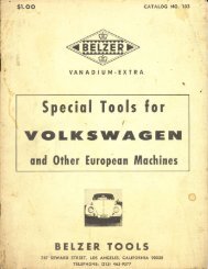
Let’s look at one more schematic diagram,<br />
this time the backup light circuit<br />
in Fig. 3 (page 39). Again, it’s a current<br />
flow diagram, with all of the circuit<br />
<strong>com</strong>ponents laid out end to end. All of<br />
the wires, connectors and other <strong>com</strong>ponents<br />
are clearly labeled and identified.<br />
At the bottom of the diagram, note the<br />
circled numbers 7 and 8. These refer to<br />
the actual locations of the ground connections<br />
indicated in the diagram. An<br />
ac<strong>com</strong>panying vehicle diagram shows<br />
you where the grounds are located.<br />
The schematic <strong>diagrams</strong> used here<br />
are admittedly on the basic side. When<br />
the system involved is more <strong>com</strong>plicated,<br />
several circuits may be included in<br />
the same diagram. Just remember,<br />
Flasher Relay (Pulse Generator)<br />
51 . . . . . . . . . .Input<br />
49a . . . . . . . . .Output<br />
49b . . . . . . . . .Output to Second Flasher Relay<br />
49c . . . . . . . . .Output to Third Flasher Relay<br />
Battery Switching Relay<br />
50a . . . . . . . . .Output for Starter Control<br />
Start-Locking Relay<br />
50e . . . . . . . . .Input<br />
50f . . . . . . . . .Output<br />
Start-Repeating Relay<br />
50g . . . . . . . . .Input<br />
50h . . . . . . . . .Output<br />
AC Generator (Alternator)<br />
51 . . . . . . . . . .DC Voltage at Rectifier<br />
51e . . . . . . . . .DC Voltage at Rectifier with Choke Coil<br />
for Daylight Operation<br />
Starter<br />
52 . . . . . . . . . .Starter Control (Direct)<br />
53 . . . . . . . . . .Wiper Motor, Input (+)<br />
53a . . . . . . . . .Wiper (+), End Position<br />
53b . . . . . . . . .Wiper (Shunt Winding)<br />
53c . . . . . . . . .Electric Windshield Washer Pump<br />
53e . . . . . . . . .Wiper (Brake Winding)<br />
53i . . . . . . . . .Wiper Motor with Permanent Magnet & Third Brush<br />
(for Higher Speed)<br />
55 . . . . . . . . . .Front Fog Lamp<br />
56 . . . . . . . . . .Headlights<br />
56a . . . . . . . . .High Beam with Indicator Lamp<br />
56b . . . . . . . . .Low Beam<br />
56d . . . . . . . . .Headlight Flasher Contact<br />
57 . . . . . . . . . .Parking Lamps (in some export markets)<br />
57a . . . . . . . . .Parking Lamps<br />
57L . . . . . . . . .Parking Lamps, Left<br />
57R . . . . . . . . .Parking Lamps, Right<br />
these more <strong>com</strong>plicated schematic <strong>diagrams</strong><br />
are assembled using the same<br />
basic building blocks and DIN conventions<br />
found in the simpler <strong>diagrams</strong>.<br />
When you’re troubleshooting a specific<br />
circuit problem, learn to home in on<br />
the part of the circuit that’s involved,<br />
and tune out all the clutter around it. If<br />
necessary, make a disposable copy of<br />
the diagram, then mark it up with colored<br />
pens or pencils until you understand<br />
how the circuit works.<br />
DIN Relays<br />
Suppose you’re diagnosing a relay in an<br />
electrical circuit. Perhaps the <strong>wiring</strong> diagram<br />
shows only a square box, with no<br />
information about what’s going on in-
Terminal Definition Terminal Definition<br />
58 . . . . . . . . . .Side-Marker Lamps, Taillamps, License Plate<br />
& Instrument Illumination<br />
58d . . . . . . . . .Rheostatic Instrument Illumination, Tail- & Side-Marker Lamps<br />
58L . . . . . . . . .Left<br />
58R . . . . . . . . .Right, License Plate Lamps<br />
AC Generator (Alternator)<br />
(Magneto Generator)<br />
59 . . . . . . . . . .AC Voltage Output, Rectifier Input<br />
59a . . . . . . . . .Charging-Armature Output<br />
59b . . . . . . . . .Taillamp Armature, Output<br />
59c . . . . . . . . .Stop-Lamp Armature, Output<br />
61 . . . . . . . . . .Charge Indicator Lamp<br />
Tone-Sequence Controller<br />
71 . . . . . . . . . .Input<br />
71a . . . . . . . . .Output to Horns I & II (Bass)<br />
71b . . . . . . . . .Output to Horns 1 & 2 (Treble)<br />
75 . . . . . . . . . .Radio, Cigarette Lighter<br />
76 . . . . . . . . . .Speakers<br />
77 . . . . . . . . . .Door Valve Control<br />
Switches, Normally Closed (NC) Contacts & Changeover Contacts<br />
81 . . . . . . . . . .Input<br />
81a . . . . . . . . .First Output on NC-Contact Side<br />
81b . . . . . . . . .Second Output on NC-Contact Side (NO Contacts)<br />
82 . . . . . . . . . .Input<br />
82a . . . . . . . . .First Output<br />
82b . . . . . . . . .Second Output<br />
82z . . . . . . . . .First Input<br />
82y . . . . . . . . .Second Input<br />
Multiple-Position Switch<br />
83 . . . . . . . . . .Input<br />
83a . . . . . . . . .Output (Pos. 1)<br />
83b . . . . . . . . .Output (Pos. 2)<br />
83L . . . . . . . . .Output (Left)<br />
83R . . . . . . . . .Output (Right)<br />
Current Relay<br />
84 . . . . . . . . . .Input: Actuator & Relay Contacts<br />
84a . . . . . . . . .Output: Actuators<br />
84b . . . . . . . . .Output: Relay Contacts<br />
side the relay. Or maybe you need to<br />
bench-test the relay or jumper the connector<br />
but can’t see the wire colors. If<br />
the vehicle uses DIN standards, the relay<br />
will provide you with information<br />
about its inner workings, just by looking<br />
at its terminal numbers. And for a more<br />
thorough explanation, many DIN relays<br />
even include a tiny schematic diagram<br />
on the outside of the housing.<br />
Relays are electrically controlled<br />
switches. The switch inside the relay<br />
will be in one of two positions, depending<br />
on whether the electromagnetic<br />
relay coil is energized or deenergized.<br />
In basic relays, there’s one input<br />
and either one or two outputs. Relays<br />
are either normally open (NO) or nor-<br />
Switching Relay<br />
85 . . . . . . . . . .Output: Actuator (Negative Winding End or Ground)<br />
Input: Actuator<br />
86 . . . . . . . . . .Start of Winding<br />
86a . . . . . . . . .Start of Winding or First Winding Coil<br />
86b . . . . . . . . .Winding Tap or Second Winding Coil<br />
Normally Closed (NC) Relay Contact & Changeover Contacts<br />
87 . . . . . . . . . .Input<br />
87a . . . . . . . . .First Output (NC-Contact Side)<br />
87b . . . . . . . . .Second Output<br />
87c . . . . . . . . .Third Output<br />
87z . . . . . . . . .First Input<br />
87y . . . . . . . . .Second Input<br />
87x . . . . . . . . .Third Input<br />
Normally Open (NO) Relay Contact<br />
88 . . . . . . . . . .Input<br />
88z . . . . . . . . .First Input<br />
88y . . . . . . . . .Second Input<br />
88x . . . . . . . . .Third Input<br />
Normally Open (NO) Relay Contact & Changeover Contacts (NO Side)<br />
88a . . . . . . . . .First Output<br />
88b . . . . . . . . .Second Output<br />
88c . . . . . . . . .Third Output<br />
Generator/Alternator & Voltage Regulator<br />
B� . . . . . . . . .Battery Positive Terminal<br />
B� . . . . . . . . .Battery Negative Terminal<br />
D� . . . . . . . . .Generator Positive Terminal<br />
C� . . . . . . . . .Generator Negative Terminal<br />
DF . . . . . . . . . .Generator Field Winding<br />
DF1 . . . . . . . . .Generator Field Winding 1<br />
DF2 . . . . . . . . .Generator Field Winding 2<br />
Alternator<br />
U, V, W . . . . . .Three-Phase Terminals<br />
Turn Signals (Turn-Signal Flasher)<br />
C . . . . . . . . . . .Indicator Lamp 1<br />
C0 . . . . . . . . . .Main Terminal Connection for Indicator Lamp Not<br />
Connected to Turn-Signal Flasher<br />
C2 . . . . . . . . . .Indicator Lamp 2<br />
L . . . . . . . . . . .Left-Side Turn Signals<br />
R . . . . . . . . . . .Right-Side Turn Signals<br />
mally closed (NC). In either case, the<br />
relay switch input is always connected<br />
to pin 30. Pin 30 not only designates<br />
the input to the relay switch, but in accordance<br />
with DIN standards, we also<br />
know that it’s connected to battery positive.<br />
The relay outputs on the other<br />
side of the relay switch are designated<br />
either 87, 87a or 87b.<br />
The two remaining relay terminals<br />
are connected to the relay coil. Applying<br />
current to the coil is what makes the<br />
relay close or open. According to DIN<br />
standards, pin 85 should be connected<br />
to ground (usually controlled by another<br />
switch) and pin 86 should be connected<br />
to battery positive (usually protected by<br />
a fuse). This one is not a hard and fast<br />
rule, apparently, as you may encounter<br />
relays where the polarities of terminals<br />
85 and 86 have been reversed.<br />
How does DIN pin number information<br />
help in the real world? By using pin<br />
information, you may be able to reduce<br />
the amount of time spent with locator<br />
manuals. When you remove a relay or<br />
look at a connector, you should be able<br />
to figure out how it works just by looking<br />
at the pin assignments.<br />
Visit www.motor.<strong>com</strong> to<br />
download a free copy of this<br />
article. Copies are also available<br />
by sending $3 for each copy to:<br />
Fulfillment Dept., MOTOR Magazine,<br />
5600 Crooks Rd., Troy, MI 48098.<br />
April 2003<br />
43