FROM ISLANDING PROTECTION TO ISLANDING ... - UfE GmbH
FROM ISLANDING PROTECTION TO ISLANDING ... - UfE GmbH
FROM ISLANDING PROTECTION TO ISLANDING ... - UfE GmbH

You also want an ePaper? Increase the reach of your titles
YUMPU automatically turns print PDFs into web optimized ePapers that Google loves.
<strong>FROM</strong> <strong>ISLANDING</strong> <strong>PROTECTION</strong> <strong>TO</strong> <strong>ISLANDING</strong> CONTROL<br />
10 Years of Experience with ENS Safety Interface<br />
Klaus Köln, Axel Grabitz<br />
<strong>UfE</strong> <strong>GmbH</strong><br />
18059 Rostock, Joachim-Jungius-Str. 9<br />
klaus.koeln@ufegmbh.de<br />
Purpose of the Work:<br />
The purpose is to show the progress in Islanding Control Interfaces based on Grid Impedance Step Monitoring<br />
Background:<br />
The last generation of <strong>UfE</strong> ENS (automatic disconnection device) is reaching an excellent level in safety and performance.<br />
The devices are meeting the new release of the DIN VDE 0126 prestandard. With the approved functional safety defined in<br />
the DIN VDE 0126 there is no need of repeated testing procedures.The <strong>UfE</strong> ENS is used as a separate device or integrated<br />
in inverters including Fronius, Aixcon, Mastervolt, Pairan, Philips and Xantrex.<br />
Innovation:<br />
The use of impedance step monitoring allows a lower grid frequency limit and a resulting support to grid stability without<br />
the problems of a larger Non Detection Zone (NDZ). The improvements are based on a lot of new methods like:<br />
new methods of mesurement<br />
self optimizing switching level<br />
automatic calibration and self test<br />
automatic syncronization and signal limiting in parallel connections<br />
automatic optimization of signal patterns.<br />
Results:<br />
Performance of ENS has been testet by the ISET in Kassel using 15 ENS26 Devices in parallel connection with up to 16<br />
different inverters and 15 BISI units (The BISI is deveoped in the SIDENA Project by ISET as another safety interface<br />
using Impedance Step Monitoring). The devices showed best performance even under these critical conditions.<br />
The ENS is not only used in PV-Systems but also in any other DG (Distributed Generation) systems connected to the low<br />
voltage grid. ( small wind and hydro systems, motor- , sterling- and fuell-cell CHP). The multiple use of different methods<br />
and – if neccessary different country settings- allows to meet any requirements. A new function is the automatic passive<br />
synchronization of controlled islanding inverters or synchronous machines to support back-up supply without interruption.<br />
The latest development is a three-phase ENS with integrated relais. These type of relays use permanent magnets for contact<br />
pressure. No power is needed to keep a switching state. This saves installation and wiring of external contactors and their<br />
energy consumtion.<br />
Conclusions:<br />
Many years of field experience in Germany ,Austria, Belgium, France and the ISET research shows that improved<br />
Impedance Step Monitoring is a secure method to detect uncontrolled islanding even under balanced load conditions where<br />
passive methods could fail.<br />
Background:<br />
Impedance step monitoring as a method to detect<br />
uncontrolled islanding of grid connected inverters was first<br />
used in the <strong>UfE</strong> NEG 1500 Inverter in 1992. In islandig<br />
tests this Inverter could not be forced into islanding<br />
conditions by matched load and generation.<br />
So this method was used to establish the new ENS -<br />
standard of grid monitoring for PV-inverters in Germany.<br />
Also new was a level of approved functional safety,<br />
defined in the drafts of the new standard. The typical Non<br />
Detection Zone (NDZ) known from the passive methods<br />
monitoring frequency and voltage does not accur with the<br />
new method. But there had been some problems with<br />
overreaction. Some inverters using the ENS reacted too<br />
sensible under special grid conditions like remote houses<br />
conneted with long overhead wires. There were also<br />
problems with multiple use of inverters, the ENS systems<br />
could disturbe each other. But about 98% of the<br />
installations had no problems with overreaction of the<br />
ENS. There is also in other coutries the concern of grid<br />
interference with the use of many ENS systems adding<br />
their test signals. But the main background of this concern<br />
was not the <strong>UfE</strong> ENS using a low reactive current of 50<br />
Hz but another producer of inverters using high current<br />
sharp pulses as test signals. Another problem was related<br />
to high levels of remote control signals in the grid<br />
disturbing the impedance mesurement.<br />
These problems are solved.<br />
<strong>UfE</strong> specialized in the ENS technology and developed<br />
seperate devices that could be used with any inverters.<br />
Two patents were issued on special methods of impedance<br />
measurment and ENS devices and the technology was also<br />
used in licence by other inverter producing companies.<br />
There were Fronius, Sunpower, Sunways, Sputnik<br />
Engineering, Wuseltronik, Aixcon and later Mastervolt,<br />
Pairan, Philips and Xantrex. There must be more than<br />
100,000 of Inverters running with <strong>UfE</strong>-ENS until now.<br />
The ENS was not used only in PV Systems but also in<br />
small CHP units.<br />
<strong>UfE</strong> did a lot of research and developement to solve the<br />
problems with overreaction and paralled operation. The<br />
new generation of ENS Systems (ENS26 and ENS31) is<br />
used since 4 years and is demonstrating excellent<br />
performance.<br />
Innovation:<br />
Improved methods of impedance mesurement were used:<br />
Different signal patterns, synchronisation of parallel<br />
operating ENS forming a kind of decentral pilot tone and<br />
regulation of the level of this signal according to the<br />
quantity of ENS devices and grid conditions. A new<br />
method is used to adept the switching level of impedance<br />
step monitoring to the noise of the grid without loosing<br />
safety.
Results:<br />
The ISET Institute in Kassel did some research on parallel<br />
operation of Inverters and separate islanding protection<br />
devices. Different inverters, 15 ENS26 and 15 BISI units<br />
were tested. (the BISI Bidirectional Safety Interface) is<br />
another system using impedance step monitoring. It was<br />
developed by ISET in the SIDENA Project. ISET tested<br />
up to 15 ENS or BISI devices in parallel operation<br />
connected to a single phase together with up to 16<br />
Inverters. Even under this extremly difficult conditions the<br />
ENS and also the BISI demonstrated excellent functional<br />
safety.<br />
Tests were also performed with a resonant cicuit. The<br />
results show that impedance step monitoring is easily able<br />
to pass these kind of islanding test procedures. This is the<br />
chance to discriminate between unsufficient generation in<br />
the grid and uncontrolled islanding and to support grid<br />
stability.<br />
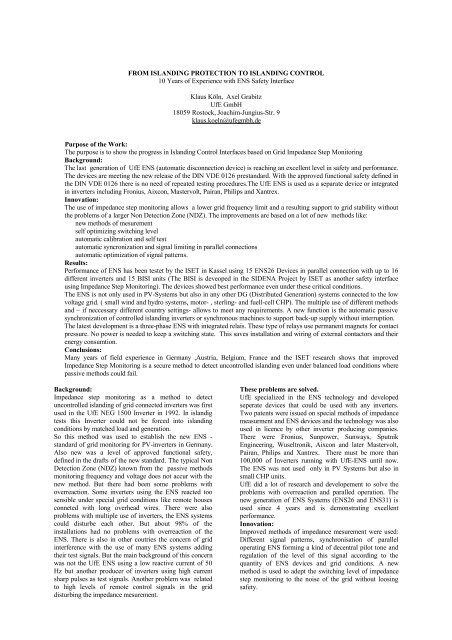
Results from ENS Dataloggers:<br />
Each of the new ENS devices has a memory chip for<br />
datalogging integrated. The datalogger is recording one<br />
second samples of 16 classes of impedance step maxima.<br />
The sums are recorded every 8 hours and in any case of<br />
fault. Fault reasons are recorded. Because of this, there is<br />
an undervoltage record every time the power supply (grid)<br />
is switched off.Impedance step data recorded from two<br />
ENS26.<br />
Data recorded showing very low levels of impedance<br />
steps. Two ENS26 devices were recorded for 85,5 and<br />
101 days. The blue record shows data of an ENS26<br />
operated in parallel with an older ENS25. There is no<br />
synchronisation with these different devices. This might<br />
be the reason of a few recorded impedance steps of more<br />
than 0,3 Ohms. The other device was running in the <strong>UfE</strong><br />
buero.<br />
Impedance step data recorded from two ENS26<br />
Data recorded showing very low levels of impedance<br />
steps. Two ENS26 devices were recorded for 85,5 and<br />
101 days. The blue record shows data of an ENS26<br />
operated in parallel with an older ENS25. There is no<br />
synchronisation with these different devices. This might<br />
be the reason of a few recorded impedance steps of more<br />
than 0,3 Ohms.<br />
The other device was running in the <strong>UfE</strong> buero.
6250000<br />
6000000<br />
5750000<br />
5500000<br />
5250000<br />
5000000<br />
4750000<br />
4500000<br />
4250000<br />
4000000<br />
3750000<br />
3500000<br />
3250000<br />
3000000<br />
2750000<br />
2500000<br />
2250000<br />
2000000<br />
1750000<br />
1500000<br />
1250000<br />
1000000<br />
750000<br />
500000<br />
250000<br />
6000000<br />
5750000<br />
5500000<br />
5250000<br />
5000000<br />
4750000<br />
4500000<br />
4250000<br />
4000000<br />
3750000<br />
3500000<br />
3250000<br />
3000000<br />
2750000<br />
2500000<br />
2250000<br />
2000000<br />
1750000<br />
1500000<br />
1250000<br />
1000000<br />
7500 00<br />
5000 00<br />
2500 00<br />
0<br />
0<br />
Impedance<br />
Zeile 2 -0,3 -0,15 0 0,1 0,2 0,3 0,4 0,5 0,6 0,7 0,8 0,9 1 1,1 1,2 1,3 1,4 1,6 2 2,4 2,8<br />
Impedance step<br />
DR Ohms -1,6 -1,3 -1 -0,7 -0,5 -0,3 -0,2 -0,1 0 0,1 0,2 0,3 0,5 0,7 1 1,3 1,6<br />
Solarverlag<br />
Büro<br />
Solarverlag85,5d<br />
Büro 101,5d<br />
Conclusions:<br />
There are more than 10 years of field experience with<br />
ENS-Systems in PV-Inverters and also with seperate<br />
devices not only in Germay, but also in Austria, Belgium<br />
and France.<br />
There was also a lot of research and testing done with the<br />
new Islanding protection Systems. There is very good<br />
performance demonstated by the latest generation of<br />
divices.<br />
The early problems with overreaction are solved. There<br />
are no grid interferences even with massive use of ENS<br />
systems.A wider range of frequency limits is possible with<br />
the use of impedance step monitoring as a secure method<br />
to detect uncontrolled islanding.<br />
Secure methods to discriminate between uncontrolled<br />
islanding and an unsufficient balance between load and<br />
generation give the chance to support grid stability.The<br />
existing guidlines and standards for integrating<br />
Distrebuted Energy Resources (DER) into the low voltage<br />
grid are still based on the assumption of a few percent<br />
added to the conventional generated amount of Power.<br />
This is not enough to meet the requirements of the<br />
future.This future will be powered by renewable Energy.<br />
The PV-Systems of the future will be able to operate grid<br />
connected as well as in stand lone or mini grid conditions.<br />
Inverters will controll and stabilize frequency and voltage<br />
of future energy networks. Grid control technologies and<br />
standards will have to meet these challenges.<br />
THREE-PHASE ENS <strong>ISLANDING</strong> CONTROL<br />
DEVICE WITH INTEGRATED RELAYS<br />
The latest ENS development is new three-phase device<br />
with integrated relays. These are polarized trip relays that<br />
need only energy for the moments of switching (about<br />
20ms) . Contact pressure is per- formed by permanent<br />
magnets. The switching capability is up to 100A..<br />
Simplified grid connection of three phased systems:<br />
Until now a three phased ENS had to be installed together<br />
with two external contactors. Auxilary contacts had to be<br />
wired for monitoring the switching status of each of the<br />
contactors.<br />
Contactors saved:<br />
Costs for contactors and wiring are saved, also some space<br />
in the electrical cabinet. The new housing with seperated<br />
terminal box could also be installed without an electrical<br />
cabinet.<br />
Energy saved:<br />
The new ENS is saving the whole energy that would be<br />
necessary to drive two conventionell contators.With PVsystems<br />
and their EEG based high energy prices 20-60<br />
Euros per year could be saved. This will sum up to 400-<br />
1200 Euros in 20 years!<br />
Safety:<br />
The use of polarized trip relays is a novum in safety<br />
related electric applications because energy is needed to<br />
switch to a safe condition. The new ENS is storing this<br />
energy in capacitors. The capacity and charge of these<br />
capacitors are permanently monitored by microprocessors.<br />
With any fault in the system all relays are switched off<br />
instantly using this energy. For there are two sets of relays<br />
connected in series switching off is guaranteed even if a<br />
relay itself is failing.<br />
EINSPEISER<br />
1<br />
3<br />
5<br />
-K10.1<br />
R1R2R3R4<br />
RELAIS<br />
21<br />
-K10.1<br />
22<br />
<strong>UfE</strong> - ENS31<br />
2<br />
4<br />
6<br />
A1 A2<br />
21<br />
-K10.2<br />
22<br />
1<br />
3<br />
5<br />
K1 K2<br />
N L1 L2 L3<br />
KONTAKTE NETZ<br />
2<br />
4<br />
6<br />
A1 A2<br />
-K10.2<br />
N<br />
L1<br />
L2<br />
L3<br />
NETZ<br />
* * * min. 6 A<br />
max. 25 A
CONCLUSIONS<br />
There are more than 10 years of field experience with<br />
ENS-Systems in PV-Inverters and also with seperate<br />
devices not only in Germay, but also in Austria, Belgium<br />
and France.<br />
There was also a lot of research and testing done with the<br />
new Islanding protection Systems. There is very good<br />
performance demonstated by the latest generation of<br />
divices.<br />
The early problems with overreaction are solved. There<br />
are no grid interferences even with massive use of ENS<br />
systems.A wider range of frequency limits is possible with<br />
the use of impedance step monitoring as a secure method<br />
to detect uncontrolled islanding.<br />
Secure methods to discriminate between uncontrolled<br />
islanding and an unsufficient balance between load and<br />
generation give the chance to support grid stability.The<br />
existing guidlines and standards for integrating<br />
Distrebuted Energy Resources (DER) into the low voltage<br />
grid are still based on the assumption of a few percent<br />
added to the conventional generated amount of Power.<br />
This is not enough to meet the requirements of the future.<br />
This future will be powered by renewable Energy. The<br />
PV-Systems of the future will be able to operate grid<br />
connected as well as in stand lone or mini grid conditions.<br />
Inverters will controll and stabilize frequency and voltage<br />
of future energy networks. Grid control technologies and<br />
standards will have to meet these challenges.