
Create successful ePaper yourself
Turn your PDF publications into a flip-book with our unique Google optimized e-Paper software.
10 I TREDESS<br />
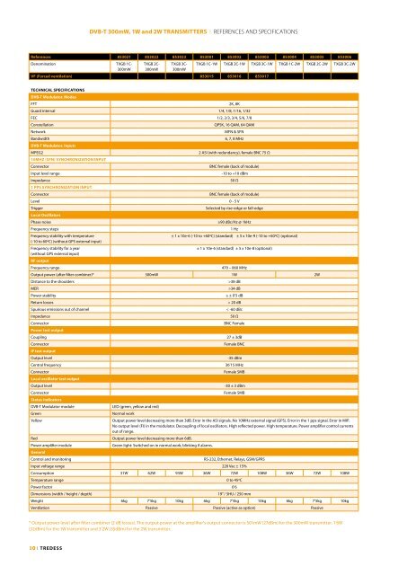
DVB-T 300mW, 1W and 2W TRANSMITTERS I REFERENCES AND SPECIFICATIONS<br />
References 853021 853022 853023 853001 853002 853003 853004 853005 853006<br />
Denomination TXGB 1C-<br />
300mW<br />
TXGB 2C-<br />
300mW<br />
TXGB 3C-<br />
300mW<br />
VF (Forced ventilation) 853015 853016 853017<br />
TECHNICAL SPECIFICATIONS<br />
TXGB 1C-1W TXGB 2C-1W TXGB 3C-1W TXGB 1C-2W TXGB 2C-2W TXGB 3C-2W<br />
DVB-T Modulator. Modes<br />
FFT 2K, 8K<br />
Guard interval 1/4, 1/8, 1/16, 1/32<br />
FEC 1/2, 2/3, 3/4, 5/6, 7/8<br />
Constellation QPSK, 16 QAM, 64 QAM<br />
Network MFN & SFN<br />
Bandwidth<br />
DVB-T Modulator. Inputs<br />
6, 7, 8 MHz<br />
MPEG2<br />
10MHz (SFN) SyNCHRONIzATION INPUT<br />
2 ASI (with redundancy), female BNC 75 Ω<br />
Connector BNC female (back of module)<br />
Input level range -10 to +10 dBm<br />
Impedance<br />
1 PPS SyNCHRONIzATION INPUT<br />
50 Ω<br />
Connector BNC female (back of module)<br />
Level 0 - 5 V<br />
Trigger<br />
Local Oscillators<br />
Selected by rise-edge or fall-edge<br />
Phase noise ≥90 dBc/Hz @ 1kHz<br />
Frequency steps 1 Hz<br />
Frequency stability with temperature<br />
(-10 to 60ºC) (without GPS external input)<br />
± 1 x 10e-6 (-10 to +60ºC) (standard) ± 5 x 10e-9 (-10 to +60ºC) (optional)<br />
Frequency stability for a year<br />
(without GPS external input)<br />
RF output<br />
± 1 x 10e-6 (standard) ± 5 x 10e-8 (optional)<br />
Frequency range 470 – 860 MHz<br />
Output power (after filter combiner)* 300mW 1W 2W<br />
Distance to the shoulders >38 dB<br />
MER >34 dB<br />
Power stability ≤ ± 0’5 dB<br />
Return losses > 20 dB<br />
Spurious emissions out of channel < -60 dBc<br />
Impedance 50 Ω<br />
Connector<br />
Power test output<br />
BNC Female<br />
Coupling 27 ± 3dB<br />
Connector<br />
IF test output<br />
Female BNC<br />
Output level -35 dBm<br />
Central frequency 36’15 MHz<br />
Connector<br />
Local oscillator test output<br />
Female SMB<br />
Output level -30 ± 3 dBm<br />
Connector<br />
Status indicators<br />
Female SMB<br />
DVB-T Modulator module LED (green, yellow and red)<br />
Green Normal work<br />
Yellow Output power level decreasing more than 3dB. Error in the ASI signals. No 10MHz external signal (GPS). Error in the 1 pps signal. Error in MIP.<br />
No output level (FI) in the modulator. Decoupling of local oscillators. High reflected power. High temperature. Power amplifier control currents<br />
out of range.<br />
Red Output power level decreasing more than 6dB.<br />
Power amplifier module<br />
General<br />
Green light: Switched on in normal work; blinking if alarms.<br />
Control and monitoring RS-232, Ethernet, Relays, GSM/GPRS<br />
Input voltage range 220 Vac ± 15%<br />
Consumption 31W 62W 93W 36W 72W 108W 36W 72W 108W<br />
Temperature range 0 to 45ºC<br />
Power factor 0’6<br />
Dimensions (width / height / depth) 19” / 5HU / 250 mm<br />
Weight 6kg 7’5kg 10kg 6kg 7’5kg 10kg 6kg 7’5kg 10kg<br />
Ventilation Passive Passive (active as option) Passive<br />
* Output power level after filter combiner (2 dB losses). The output power at the amplifier’s output connector is 501mW (27dBm) for the 300mW transmitter, 1’6W<br />
(32dBm) for the 1W transmitter and 3’2W (35dBm) for the 2W transmitter.