Ares 2 system - WTS Broadcast
Ares 2 system - WTS Broadcast
Ares 2 system - WTS Broadcast
- No tags were found...

You also want an ePaper? Increase the reach of your titles
YUMPU automatically turns print PDFs into web optimized ePapers that Google loves.
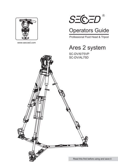
Operators GuideProfessional Fluid Head & Tripodwww.secced.com<strong>Ares</strong> 2 <strong>system</strong>SC-DV/6/75VPSC-DV/AL75DRead this first before using and save it
<strong>Ares</strong> 2Fluid Head & TripodSC-DV6/75VPSC-DV/AL75DFluid Head Page 3Tripod Page 12Floor spreaderPage 17Copyright C Beijing Secnovo Co., Ltd 2007All right reserved throughtout the world. No part of this document may be stored in a retrieval <strong>system</strong>,transmitted, copied or reproduced in any way including, but not limited to, photocopy, photograph,magnetic or other record without the prior agreement and permission in writing ofBeijing Secnovo Co., LtdSecced is registered trademarks of Beijing Secnovo Co., LtdPrinted in People Republic of China by Secnovo, Beijing.
Safety – Read this firstWarning Symbols in this Operators GuideWhere there is a risk of personal injury, injury to others, or damage to the <strong>Ares</strong>2<strong>system</strong> or associated equipment, comments appear, highlighted by the word.WARNING! And supported by the warning triangle symbol.Technical DataFluid HeadWeight(complete with pan bar and bowl clamp)2.8 kg / 6.2 lbPayload range2 to 6 kg / 4 to 13 lbCounterbalance0 to 4 stepBlance plate60mmGrades of dragHorizontal0 to 3 gradesVertical0 to 3 gradesTilt range-75 to +90 under maximum payload capacityDiameter of bowl75 mmTripodWeightPayload capacityHeight3.45kg / 7.6lb30kg / 66lb59-156cmFurther informationFor further information or advice regarding this <strong>Ares</strong> 2 <strong>system</strong>, please contactBeijing Secnovo Co., Ltd or your local distributor.For full details on maintenance and spare parts, please refer to the <strong>Ares</strong> 2 <strong>system</strong>Maintenance Manual and Illustrated Parts List. This is obtainable fromBeijing Secnovo Co., Ltd or your local distributor.www.secced.com1
IntroductionThe <strong>Ares</strong> 2 <strong>system</strong> include SC-DV6/75VP fluid head, SC-DV/AL75D tripod and floor spreader.The SC-DV6/75VP embodies 5 steps counterbalancing mechanism and the adjustable dragaseemblies for pan and tilt motions.The balance <strong>system</strong> is easily adjusted by a knob on the right-hand side of the head. The drag<strong>system</strong> ensures smooth movement of the camera about pan and tilt axes and are fitting withcontrol knobs to adjust the drag setting.Friction brakes on each axis allow the head to be locked at any position. The camera is attachedto the head by means of a Quicklock wedge fitted into camera plate of head.The SC-DV/AL75D features the fast clamping mechanism for locking the leg. The rubber foot,dolly and floor spreader are available as accessories. The 75mm bowl base is an ideal supportfor 75mm fluid head of all brands.2
Fig 1(5)(5)(1)(6)(2)(7)(8)(3)SC-DV6/75VP (Left-Hand Side)(1) Tilt drag adjustment knob(2) Pan drag adjusment knob(3) Bowl clamp(4) Slide lock release(5) Pan bar mounting(6) Tilt brake knob(7) Pan brake knob(8) Head bowl4
Fig 2(11)(12)(13)(9)(14)(10)SC-DV4/75VP (Right-Hand Side)(9) Balance knob(10) Level bubble(11) Sliding plate(12) Slide plate clamp(13) Pan bar clamping sleeve(14) Pan bar clamping lever5
OperationInstalling the head on a tripodThe <strong>Ares</strong> 2 fluid head is supplied with an integral 75mm ball mount, designed for installationon a compatible Secnovo tripod.To install the head, remove the bowl clamp (4) from the head (turn bowl clamp anti-clockwiseas in Figure 3), position the head on the tripod and refit the bowl clamp from below. Level thehead with aid of level bubble (11) and apply the bowl clamp(turn bowl clamp clockwise asin Figure 3).Fig 3<strong>Ares</strong> 2 head (SC-DV6/75VP)<strong>Ares</strong> 2 tripod (SC-DV/AL75D)Loosen the bowl clamp (Anti-clockwise)(4)Tighten the bowl clamp (Clockwise)Installing the head on a tripod6
Opening the pan barOpen the black clamping lever (14) of the pan bar and move the pan bar into the desired position.Apply the clamping lever of the pan bar (Turn the clamping lever clockwise as in Figure 4).During transportation the pan bar can be moved next to the tripod legs.WARNING! Open the clamping lever of the pan bar far enough. The teeth of the pan barclamp should not clatter while moving the pan bar. However, a plastic protector,clamping washer (15) prevents against wear of metal toothed ring. Make sure thatthe teeth interleave with each other when closing the clamping lever of the pan bar.Fig 4Tighten the clamping lever (Clockwise)(13)(14)(16)(15)Installing the pan bar on a head7
Use of the enclosed pan bar on the left side of the fluid head is also possible. For this, it isadvisable to relocate the clamp on the pan bar. The pan bar has to be removed from the headand the black plastic cap (16) on its top should be opened and removed with a coin or screwdriver.The toothed clamping sleeve (13) should be removed and relocated as in Figure 5. The plasticscrewed cap need to be tightened again.Fig 4(16)(13)Left-handed pan bar8
Mounting the cameraTighten the tilt brake before mounting the cameraRemove the slide plate (11) from the head by releasing the slide plate clamp (12), pressing theslide lock release (5) and pulling the plate out to the rear (as shown in Fig 6).Fit the slide plate to the DV or HDV camera with 3/8 screw (11.1) provided (as shown below).Tighten the 3/8 screw with a coin or screwdriver to make sure the slide plate attachedwith camera closely.Fig 6(12)(17)(11.1)(5)(11)Pressing down (5)Release the slide plate clamp (Anti-clockwise)(11)(11.1)9
Insert the slide plate into the slide plate platform (17) until an audible click indicates that the slideplate is locked in position. Please make sure the whole <strong>system</strong> to form the appreance as in Fig 7.Fig 7(17)Insert sliding plate10
012Balancing the headBalancing the head achieves two objectives. Firstly, when the head is correctly balanced theoperator will need a minimum amount of effort to move the head. Secondly, once balanced,the head and its payload can be set to any tilt position and the head will maintain this positionwith ‘hand off’.Prior to balancing the head ensure that the pan bars and ancillary equipment have been fittedin order to prevent upsetting the balance once it has been achieved.WARNING!Be prepared to prevent the head falling away suddenly.I. Release the tilt brake (6).II. Turn the balance knob to position 0 and keep holding the camera.III. Turn the tilt drag to position 0.IV. Hold the camera in the horizontal position by securing the pan bar. Releasethe slide plate clamp (12) and slide the camera backwards or forward until itbalances horizontally. Tighten the slide plate clamp.V. Turn the balance knob to the number which best compensates for the weight ofthe camera, i.e. for as little movement upward or downword in any position.VI. Select the tilt drag level by turning the tilt drag knob (2). In the correctly chosenposition the camera should not perform any tilt movement.Fig 8IIIPosition 0Release the tilt brake11
01201230123Fig 8 continuedIIIVPosition 0IVVIRelease slide clamp knobTighten slide clamp knob12
Pan and tilt brakesFriction brakes (6,7) on each axis allow the head to be locked at any chosen position.To apply the brake, turn the lever fully clockwise. To release the brake, turn the levercounter-clockwise (Fig 9).WARNING!When the brakes are not in use, make sure the brakes is at the released status.DO NOT use the brakes to supplement drag.Pan and tilt dragBoth drag knobs (2,3) are provided with graduated scales (Fig 9).By turning the vertical setting and the horizontal setting, selects the desired drag level.Make sure that you always turn the setting to the next indexed position (arrow). Engage theretainer pins by slowly panning or tilting the camera.NOTE:Panning or tilting the camera with settings between the indexed positions can damagethe retainer pins and/or disks. Reduce drag to a minimum when the head is out of usefor long periods.Fig 9Increase pan or tilt dragRelease the tilt or pan brakesTighten the tilt or pan brakes13
ServicingRoutine maintenanceDuring use, check the followingCheck the condition of the clamping washer (15) and the pan bar clamping sleeve (13),replace them if the teeth of the clamping washer and clamping sleeve are almost weared away.Check the effectiveness of the slide plate, add some grease lubricant onto the slide plate ifslide plate do not move when tilting to +45° and -45° (as shown in Figure 11).Check the effectiveness of the pan and tilt drag controls. Repair as necessary.Check the effectiveness of the pan and tilt brakes. Repair as necessary.No further routine maintenance is required.CleaningDuring indoor use the only cleaning required should be a regular wipe over with a lint-free cloth.Dirt accumulated during storage may be removed using a semi-stiff brush. Particular attentionshould be given to the leveling bowl and mounting face of the head.Use out-of-doors under adverse condition will require special attention. Salt spray should bewashed off with fresh water at the earliest opportunity. Sand and dirt acts as an abrasive andshould be removed using a semi-stiff or vacuum cleaner.NOTE:Use only detergent-based cleaners. DO NOT use solvent- or oil-based cleaners,abrasives or wire brushers to remove accumulations of dirt, as these damagethe protective surfaces.Fig 1014
TripodSC-DV/AL75DContentsOperation …………………………………………… Page 13Servicing ……………………………………………… Page 15Cleaning ………………………………………………………………… Page 15Routine maintenance ……………………………………………………… Page 15Adjusting the leg clamps …………………………………………………… Page 1515
Fig 12(18)(22)(19)(20)(21)(23)SC-DV/AL75D Tripod(18) Tripod bowl(19) Top clamp assembly(20) Bottom clamp assembly(21) Floor spreader(22) Locking clip(23) Clamping knob16
OperationLift the complete tripod and head out of the case and keep the floor spreader (21) attachedto the tripod.Release the three locking clips (22), open out the legs while holding the legs. Gentle foot or handpressure on the spreader will ensure that the legs are fully spread.NOTE:Always use the spreader where possible as this increases rigidity of the tripod.Being flexible, the spreader compensates for uneven ground. It can be removedand a dolly fitted. At the fullest extension of the spreader and with all legs fullyretracted, the tripod can be used at its lowest operating height. Although the tripodcan be set up lower than this without the spreader, it is NOT recommended asthe tripod geometry becomes unstable.Fig 13Release the locking clips(22)Spread the legs17
Adjust the operating height by undoing the leg clamps (19.1, 20.1) and pulling the tripod upto the desired height. Adjust the spreader if necessary. Level the head with aid of the level bubble.Apply the clamps (19.1, 20.1) to lock the tripod.Fig 14Pull up(19.1)Lift up to releasePress down to lock(20.1)Lift up to releasePress down to lock18
ServicingCleaningDuring indoor use the only cleaning required should be a regular wipe over with a lint-free cloth.Dirt accumulated during storage may be removed using a semi-stiff brush. Particular attentionshould be given to the mounting bowl of tripod.Use out-of-doors under adverse condition will require special attention. Salt spray should bewashed off with fresh water at the earliest opportunity. Sand and dirt acts as an abrasive andshould be removed using a semi-stiff or vacuum cleaner.NOTE:Use only detergent-based cleaners. DO NOT use solvent- or oil-based cleaners,abrasives or wire brushers to remove accumulations of dirt, as these damagethe protective surfaces.Routine maintenanceDuring normal use, check the effectiveness of the leg clamps and adjust as necessary.Adjusting the leg clampsBedding-in occurs with leg clamps, which may necessitate resetting the clamp. Check theeffectiveness of each leg clamp as follows:Extend all three tripod legs fully and apply the clamps.Position each leg in turn vertically on a set of weighting scales.Gradually apply body weight to the leg until either or both clamps begin to slip. Note thereading on the scales at which this occurs.A reading of less than 30 kg (66 lb) will necessitate adjustment.19
Fig 14(19.2)(19.3)(19.5)(19.1)(19.4)(3) back off the threaded insert (Anti-clockwise)(5) Tighten the screw (21.5)(2) Remove screw (21.5) out(4) Tighten the threaded insert (Clcokwise)(1) Lift the top clamp (21.1) upTop clampAdjust a top clamp as follows (Fig 14):(1) Lift the top clamp (19.1) up.(2) Remove screw (19.5).(3) Using a suitable peg spanner, back off the threaded insert (19.2) slot by slot until the legis free to move under its own weight.(4) While sliding the leg up and down, gradually tighten the threaded insert (19.2) until theclamp begins to grip and till achieving the desired payload.If not aligned, back off the threaded insert (19.2) until a slot align with the hole for screw (19.4).(5) Install screw (19.5) to secure the threaded insert (19.2).20
Floor SpreaderSC-FS100ContentsOperation …………………………………………… Page 19Installing the floor spreader ……………………………………………… Page 19Adjusting the spreader………………………………………………………Page 1917
Fig 9(24)(26)(27)(25)(28)(29)(30)SC-FS100 Floor Spreader(24) Foot retaining strap(25) Clamping knob(26) Inner leg(27) Outer leg(28) Lift ring(29) Core connecting assembly(30) Foot support18
OperationInstalling the floor spreaderTo install a floor spreader onto a tripod proceed as follows:Unfold legs of spreader and place flat on the ground. Ensure three clamping knobs (25) areengaged.Lower tripod onto the spreader and locate the feet (31) onto the three foot supports.Secure tripod onto spreader by engaging three foot retaining straps (24) to each foot of thespreader.Fig 10(25)(32)(31)Installing the floor spreader24
Adjusting the spreaderNOTE:Always use the spreader where possible as this increases rigidity of the tripod. At thefull extension of the spreader and with all legs fully retracted, the tripod can be usedat its lowest operating height. Although tripods can be set lower than this withoutspreader, it is NOT recommended as the tripod geometry become unstable.NOTE:Floor spreaders protect floors and carpets as well as protecting the tripod legs sinkinginto soft ground and should be used at all time. If the floor spreader cannot be used,use secnovo rubber feet and middle-level spreader.Once the tripod is installed, the floor spreader can be adjusted as follows:Slacken three clamping knobs (25) on spreader.Set legs of tripod to required position and height and ensure they are locked.Once the tripod is positioned correctly, apply three clamping knobs. The spreader does not haveto be removed when collapsing the tripod.Release the clamping knob (Anti-clockwise)Tighten the clamping knob (Clockwise)(25)25
Mid-Level SpreaderSC-MS75ContentsOperation …………………………………………… Page 28Installing the mid-level spreader ………………………………………… Page 2830
Fig 19(33)(34)(35)SC-MS75 Mid-level Spreader(33) Attachment release button(34) Attachment head(35) Mid-level spreader attachment point27
OperationInstalling the mid-level spreaderThe spreader may be installed on any tripod provided with attachment points.To install the spreaderGrip the ends of each arm in turn and press in the attachment release buttons (33).Push the arm into the tripod attachment point (35) until the attachment head engageswith tripod.The rubber foot has to be used when adopting the mid-level spreader, just locate the feet (32)onto the three rubber feet (36) and engage the three foot retaining straps (25) to each foot oftripodNOTE:Ensure the open slot of attachment upward.Fig 20(33)(35)(25)(32)(36)Installing the mid-level spreader28
Remote Control Pan BarSC-DVPB-S & SC-DVPB-PContentsOperation …………………………………………… Page 31Installing the remote control pan bar …….……………………………… Page 31Controlling the camera ……......................……………………………… Page 3229
Fig 21(37)(38)(39)(40)(41)(42)Remote Control Pan Bar(37) Zoom control wheel(38) Control Panel(39) Pan bar clamping sleeve(40) Pan bar clamping lever(41) Focus control wheel(42) Pan bar clamping washer30
OperationInstalling the remote control pan barOpen the black clamping lever (40) of the pan bar and move the pan bar into the desired position.Apply the clamping lever of the pan bar (Turn the clamping lever clockwise as in Figure 22).During transportation the pan bar can be moved next to the tripod legs.WARNING! Open the clamping lever of the pan bar far enough. The teeth of the pan barclamp should not clatter while moving the pan bar. However, a plastic protector,clamping washer (42) prevents against wear of metal toothed ring. Make sure thatthe teeth interleave with each other when closing the clamping lever of the pan bar.Fig 22Tighten the clamping lever (Clockwise)(39)(40)(42)Installing the pan bar on a head31
Controlling the cameraFor SONY & CANON cameraThe SC-DVPB-S remote control pan bar works with both SOny and Canon LANC-enabledvideo camera. The remote control features a record/stop button, a power on/standby button,fader on/off button, back light on/off button, photo taking button, zoom control wheel and focuscontrol wheel.To control zoom, simplely press either ends of the zoom control wheel (37) to control zoom in orout. For focus, rotate the focus control wheel (41) to adjust focus of the lens.Fig 23(41) (37)32
Power on/standby button (38.2S): Press power on/standby button to switch on the camera.The LED (38.1S) above displays whether the camera is on or off (Constant green light=Power on). Press power on/standby button again to switch off the camera.Record/stop button (38.4S): Press record/stop button to make camera start recording. TheLED light (39.3S) above indicate if it is recording or not (Constant red light=recording).Press this button again to stop recording.Fader button (38.5S): Press fader button to start fader funtion of camera.Photo taking button (38.6S): Press this button to take photoBack light button (38.7S): Press the back light button to give back light to current image.Fig 24(38.1S)PHOTOFADER(38.2S)(38.5S)POWER(38.6S)B.L.(38.3S)(38.7S)REC(38.4S)Control Panel (Sony & Canon)33
For Panasonic cameraThe SC-DVPB-S remote control pan bar works with Panasonic DV & HDV video camera.The remote control features a record/stop button, auto/manual focus switch, iris auto/manualswitch, iris control, zoom control and focus control.As in Fig 25, to control zoom, simplely press either ends of the zoom control wheel (37) tocontrol zoom in or out. For focus, rotate the focus control wheel (41) to adjust focus of the lens.Fig 25(41) (37)34
Auto/manual iris switch (38.1P): Set this switch on ‘ON’ position to start manual controlof iris. At ‘OFF’ position, auto iris control of camera are enabled.Iris control knob (38.2P): Turn this knob to adjust iris of camera.Auto/manual focus switch (38.3P): Set this switch on ‘ON’ position to start manual controlof focus. At ‘OFF’ position, auto focus control of camera are enabled.Record/stop button (38.4P): Press record/stop button to make camera start recording.Press this button again to stop recording.Fig 26IRIS(38.1P)OFFON(38.2P)FOCUSON(38.3P)OFF(38.4P)RECControl Panel (Panasonic)35
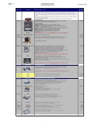
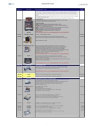
Parts ListThe folliwing lists include main assemblies,user-replaceable spare parts and optional accessories.For further information regarding repair or spare parts,please contact Beijing Secnovo Co., Ltd oryour local distributor.For information on-line,visit our website atwww.secced.comMain assembies<strong>Ares</strong> 2 Fluid headSC-DV6/75VP<strong>Ares</strong> 2 TripodSC-DV/AL75DPan bar SC-PB 15Floor spreaderSC-FS100Optional accesseries-Quickfit adaptorsMid-level spreaderSC-MS75Rubber foot SC-RF 100Sony & Canon remote control pan barSC-DVPB-SPanasonic remote control pan barSC-DVPB-PDollySC-Dolly 100LDollySC-Dolly 100HPadded bag29
Beijing Secnovo Co., LtdPrinted in China