


Create successful ePaper yourself
Turn your PDF publications into a flip-book with our unique Google optimized e-Paper software.
http://www.strobesnmore.com<br />
TECHNICAL SPECIFICATIONS INSTALLATION<br />
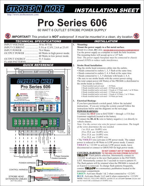
INPUT VOLTAGE .................... 10 to 30 Vdc<br />
1. Mounting:<br />
INPUT CURRENT ................... 5.5A at 12.8V, 2.6A at 25.6V<br />
INPUT POWER ........................ 70.4 Watts<br />
OUTPUT POWER .................... 60 Watts in high power mode.<br />
.................... 40 Watts in low power mode.<br />
OUTPUT ENERGY................... 51.5 Joules<br />
FLASH PATTERNS................... 15<br />
QUICK REFERENCE<br />
Mount in a clean, dry area.<br />
RED or<br />
GREEN<br />
BLACK<br />
WHITE<br />
IMPORTANT! This product is NOT waterproof. It must be mounted in a clean, dry location.<br />
400<br />
VOLTS<br />
0.565"<br />
1 2 3 4 5 6<br />
Strobe Head Outlets<br />
POWER HARNESS<br />
CONTROL HARNESS<br />
STROBE HEAD<br />
EXTENSION CABLES<br />
(NOT INCLUDED)<br />
1<br />
2<br />
3<br />
5.6"<br />
<strong>Pro</strong> <strong>Series</strong> <strong>606</strong><br />
60 WATT 6 OUTLET STROBE POWER SUPPLY<br />
WARNING!<br />
High Voltage<br />
Please wait 5 minutes after<br />
shutting this unit off before<br />
attempting service.<br />
Warranty void if seal is broken.<br />
1 2 3 4 5 6<br />
DO NOT TOUCH THE YELLOW WIRE TO<br />
THESE RED WIRES TO CHANGE PATTERNS!<br />
STROBE OUTLETS<br />
1<br />
2<br />
3<br />
OUTPUT<br />
INDICATOR<br />
1<br />
2<br />
3<br />
EZ PANEL<br />
CONNECTOR<br />
INPUT<br />
INDICATOR<br />
YELLOW<br />
GREEN<br />
BLUE<br />
RED<br />
15 AMP<br />
ATO FUSE<br />
BLACK<br />
VIOLET<br />
Power Connector<br />
Control Connector<br />
RED<br />
YELLOW<br />
GREEN<br />
BLUE<br />
6.6"<br />
Heavy duty extension cables have a GREEN wire,<br />
Light duty extension cables have a RED wire.<br />
RED or GREEN<br />
BLACK<br />
WHITE<br />
HEIGHT: 2.15"<br />
BLACK<br />
VIOLET<br />
INSTALLATION SHEET<br />
<strong>Pro</strong> <strong>Series</strong> <strong>606</strong><br />
60 WATT 6 OUTLET STROBE POWER SUPPLY<br />
INPUT VOLTAGE: 10 to 30 Vdc<br />
INPUT CURRENT: 5.5A<br />
INPUT POWER: 70 WATTS<br />
OUTPUT POWER: 60 WATTS<br />
OUTPUT INDICATOR<br />
DIAGNOSTIC INDICATORS<br />
SEE INSTALLATION SHEET FOR TROUBLESHOOTING GUIDE<br />
EZ PANEL<br />
CONTROL POWER FUSE<br />
30 VOLTS MAXIMUM!<br />
INPUT INDICATOR<br />
GND<br />
LOW<br />
POWER<br />
MADE IN<br />
U.S.A.<br />
15<br />
Mount the power supply to a flat metal surface.<br />
NEVER MOUNT IN ENGINE COMPARTMENT!<br />
Use the power supply as a template to mark the hole locations.<br />
The mounting holes will accept up to a 1/4" bolt.<br />
Note: The power supply baseplate must be connected to chassis<br />
ground (GND) to reduce radio interference.<br />
2. Strobe Head Installation:<br />
Plug the strobe head extension cables into the outlets.<br />
• Heads connected to outlets 1, 3, 5 flash at the same time.<br />
• Heads connected to outlets 2, 4, 6 flash at the same time.<br />
• Heads connected to 1, 3, 5 alternate with heads 2, 4, 6.<br />
• Be sure to use strobe heads with the correct power rating.<br />
The total output power (60 Watts) of the PRO<strong>606</strong> is distributed to<br />
the strobe heads as follows:<br />
1 Head installed and activated = 30 Watts.<br />
2 Heads installed and/or activated = 30 Watts per head.<br />
3 Heads installed and/or activated = 2 heads at 15 Watts each, 1 at 30 Watts.<br />
4 Heads installed and/or activated = 15 Watts per head.<br />
5 Heads installed and/or activated = 3 heads at 10 Watts, 2 at 15 Watts.<br />
6 Heads installed and/or activated = 10 Watts per head.<br />
3. Electrical Hookup:<br />
If you have purchased a switch panel, follow the included<br />
instructions. If you are wiring the system yourself follow the<br />
instructions below and the diagrams on the next page.<br />
POWER HARNESS:<br />
• Connect the RED wire to BATTERY + through a 15A fuse<br />
(customer supplied) located at the battery.<br />
• Connect the BLACK wire to battery negative (-) or directly to<br />
vehicle chassis.<br />
Note: Use the correct size wire for power connections. The length<br />
of the wires determines the size needed.<br />
1 to 10 ft. use 18AWG wire.<br />
10 to 20 ft. use 16AWG wire.<br />
20 to 35 ft. use 14AWG wire.<br />
35 to 50 ft. use 12AWG wire.<br />
• The VIOLET wire activates LOW power mode. The output<br />
power is reduced to 40 Watts in LOW power mode. Connect<br />
VIOLET to +12/24V to activate LOW power mode, leave<br />
disconnected or connect to GROUND for high power mode.<br />
DO NOT CONNECT ANY OF THESE WIRES<br />
CONTROL HARNESS:<br />
TO THE HIGH VOLTAGE STROBE OUTLETS!!!<br />
YELLOW: Flash pattern selection. Momentarily connect to<br />
+12/24V to advance to the next flash pattern in the PATTERN<br />
LIST. Momentarily connect for 3 seconds to reset to pattern #1.<br />
The flash pattern will be retained when the PRO<strong>606</strong> is turned off<br />
or if power is removed. To change flash patterns frequently,<br />
connect YELLOW to a momentary pushbutton located in the<br />
passenger compartment.<br />
GREEN:<br />
Activates Heads 1 & 2 when connected to +12/24V.<br />
BLUE:<br />
Activates Heads 3,4,5 and 6 when connected to +12/24V.<br />
NOTE: VIOLET, YELLOW, GREEN, and BLUE are all Low Current circuits and<br />
can be wired with a minimum of 18AWG wire.
WIRING DIAGRAM 1 FLASH PATTERN SELECTION<br />
ON/OFF and LOW POWER control.<br />
Momentarily connect YELLOW wire to +12/24V to advance to<br />
the next flash pattern in the list below. (Or use pushbutton if you<br />
installed one). The flash pattern loops back to pattern #1 when it<br />
15A FUSE<br />
is advanced past #15. If you are unsure of which flash pattern is<br />
currently selected, connect and hold YELLOW to +12/24V for 3<br />
400 VOLTS!<br />
DO NOT TOUCH<br />
YELLOW TO THE<br />
RED WIRE OF<br />
THE OUTPUTS!<br />
1<br />
2<br />
3<br />
3 2 1<br />
3 2 1<br />
1<br />
2<br />
3<br />
1<br />
2<br />
3<br />
RED<br />
BLACK<br />
VIOLET<br />
POWER HARNESS<br />
YELLOW<br />
GREEN, BLUE<br />
CONTROL HARNESS<br />
15A FUSE<br />
ON/OFF<br />
SWITCH<br />
PATTERN<br />
SELECT<br />
CHASSIS<br />
GROUND<br />
WIRING DIAGRAM 3<br />
SELECTIVE HEAD SWITCHING and PATTERN SELECT.<br />
High Power mode.<br />
1<br />
2<br />
3<br />
RED<br />
RED<br />
BLACK<br />
VIOLET<br />
POWER HARNESS<br />
YELLOW<br />
CONTROL HARNESS<br />
ON/OFF<br />
TOUCH SWITCH<br />
CHASSIS<br />
GROUND<br />
# Flash Pattern Description<br />
1 Quad Flash 4 Flash bursts alternating, 140 Quad Flashes Per Minute.<br />
2 Quintuple Flash 5 Flash bursts alternating, 140 Quintuple Flashes Per Minute.<br />
BLACK<br />
LOW<br />
POWER<br />
3<br />
4<br />
5<br />
Mega Flash<br />
Double Flash<br />
Single Flash<br />
1 Flash burst alternating, 700 Flashes Per Minute.<br />
2 Flash bursts alternating, 125 Double Flashes Per Minute.<br />
1 Flash burst alternating, 200 Single Flashes Per Minute.<br />
POWER HARNESS<br />
6 Twin Single Flash Two Single Flash bursts before alternating. 120 Twin Single Flashes Per Minute.<br />
YELLOW<br />
7<br />
8<br />
Twin Double Flash<br />
Triple Flash<br />
Two Double Flash bursts before alternating. 100 Twin Single Flashes Per Minute.<br />
3 Flash bursts alternating, 140 Triple Flashes Per Minute.<br />
9 Twin Triple Flash Two Triple Flash bursts before alternating. 70 Twin Triple Flashes Per Minute.<br />
GREEN, BLUE<br />
10 Twin Mega Flash Two Mega flash bursts before alternating. 350 Twin Mega! Flashes Per Minute<br />
CONTROL HARNESS<br />
11 Triple-Mega-Bang Three Flashes alternating then one Single Flash. 76 Flashes Per Minute.<br />
12 Warble 6 Single flashes alternating at 450 FPM, 6 single flashes alternating at 860 FPM.<br />
13 Phased Mega Flash 1 Flash burst alternating, Flash rate varies from 360 FPM to 860 FPM<br />
14 Single-Quad Single Flash - Quad Flash combination pattern.<br />
15 Cycle Flash Two warble flashes, Two Quad Flashes, Two Mega Flashes in a continuous cycle.<br />
Touch YELLOW to the terminal of the RED wire to select flash pattern.<br />
Connect YELLOW to GROUND to ensure that flash pattern will never change.<br />
WIRING DIAGRAM 2<br />
ON/OFF and PATTERN SELECT switches. High Power mode.<br />
15A FUSE<br />
OUTLETS<br />
3-4-5-6<br />
OUTLETS<br />
1-2<br />
PATTERN<br />
SELECT<br />
VIOLET<br />
GREEN<br />
BLUE<br />
CHASSIS<br />
GROUND<br />
EZ PANEL CONNECTOR<br />
• The EZ PANEL connector is only for use with the EZ<br />
PANEL series of control panels.<br />
• Do not connect both the EZ PANEL cable and the<br />
standard control wires at the same time!<br />
• Do not connect any other devices to the EZ PANEL<br />
connector as permanent damage may result.<br />
• Use only approved cables with the EZ PANEL.<br />
OUTPUT<br />
INDICATOR<br />
INPUT<br />
INDICATOR<br />
TROUBLESHOOTING<br />
DIAGNOSTIC INDICATORS<br />
The PRO<strong>606</strong> is equipped with two<br />
diagnostic indicators located on the PC board<br />
directly below the EZ PANEL connector.<br />
If the PRO<strong>606</strong> has stopped functioning check<br />
the diagnostic lights and follow the instructions<br />
below.<br />
OUTPUT INDICATOR (RED)<br />
NORMAL: The OUTPUT INDICATOR will light when ANY strobe<br />
head fires. It will blink in exact time with the flash pattern. When the<br />
PRO<strong>606</strong> is turned off the indicator may dimly blink for a few seconds.<br />
This indicates that the power supply is discharging itself.<br />
PROBLEM: If the PRO<strong>606</strong> is activated but none of the strobe heads<br />
are firing,<br />
check the OUTPUT INDICATOR. If the light is blinking or<br />
on steady then it indicates that there is a short circuit on one or more of<br />
the strobe head outputs.<br />
To find the short circuit, unplug all strobe head cables from the<br />
PRO<strong>606</strong>. Test one cable/head at a time until the problem is found. Do<br />
not test with more than one cable/head installed.<br />
The problem is typically at the strobe head end of the cable. If there is a<br />
blue/green or black colored corrosion on the connector it is shorted.<br />
Also check for a head or cable with a reverse wired connector.<br />
INPUT INDICATOR (GREEN)<br />
NORMAL: The INPUT INDICATOR should NOT be lit during<br />
normal operation. It may blink for a second when power is first applied<br />
to the PRO<strong>606</strong>, or when power is removed but this does not indicate a<br />
problem with the power supply.<br />
PROBLEM: If the PRO<strong>606</strong> is activated but none of the strobe heads<br />
are firing, check the INPUT INDICATOR. If it is ON then it indicates<br />
that the input voltage is too low (below 10V).<br />
There may be a bad connection to the battery or ground.<br />
If the PRO<strong>606</strong> is functioning but the INPUT INDICATOR is blinking<br />
or lit it indicates that the voltage is too low and the power supply is not<br />
operating at full power. Check for bad connections and be sure the<br />
proper size wire was used for the + and - connections.<br />
BLOWN FUSE<br />
The PRO<strong>606</strong> will blow a fuse if the input voltage is reversed. If this<br />
happens, first locate the wiring fault, then replace the fuse with one of<br />
the same rating. If the fuse continues to blow it indicates an internal<br />
fault. Do not use a fuse larger than 15A!